1
Home
Contents
Page:
Part 4: Instructions for programming DAC Cl. 745-26; -28
Program-Version 745A05
1.
General . . . . . . . . . . . . . . . . . . . . . . . . . . . . . . . . . . . . . . . . . . . . . . . . .
3
2.
Operator Terminal
. . . . . . . . . . . . . . . . . . . . . . . . . . . . . . . . . . . . . . . . . .
4
3.
3.1
3.2
Memory Card . . . . . . . . . . . . . . . . . . . . . . . . . . . . . . . . . . . . . . . . . . . . .
Saving and Loading Programs . . . . . . . . . . . . . . . . . . . . . . . . . . . . . . . . . . . .
Replacing the Memory Card Battery . . . . . . . . . . . . . . . . . . . . . . . . . . . . . . . . .
5
5
5
4.
4.1
4.2
Operator Interface . . . . . . . . . . . . . . . . . . . . . . . . . . . . . . . . . . . . . . . . . .
Menu Structure of the Sewing and Testing Programs . . . . . . . . . . . . . . . . . . . . . . . .
Changing of Parameter Values . . . . . . . . . . . . . . . . . . . . . . . . . . . . . . . . . . . .
6
6
7
5.
5.1
5.2
5.3
5.3.1
5.3.2
5.4
5.5
5.6
5.7
Sewing Programs . . . . . . . . . . . . . . . . . . .
Calling Up the Sewing Program Parameter Screens
Starting the Machine Program . . . . . . . . . . . .
Main Screen . . . . . . . . . . . . . . . . . . . . . .
Automatic recognition of the flap angle . . . . . . .
Sewing distance measurement . . . . . . . . . . . .
Global Parameters . . . . . . . . . . . . . . . . . . .
Pocket Programs . . . . . . . . . . . . . . . . . . . .
Pocket Sequence . . . . . . . . . . . . . . . . . . .
Seam Patterns . . . . . . . . . . . . . . . . . . . . .
.
.
.
.
.
.
.
.
.
.
.
.
.
.
.
.
.
.
.
.
.
.
.
.
.
.
.
.
.
.
.
.
.
.
.
.
.
.
.
.
.
.
.
.
.
.
.
.
.
.
.
.
.
.
.
.
.
.
.
.
.
.
.
.
.
.
.
.
.
.
.
.
.
.
.
.
.
.
.
.
.
.
.
.
.
.
.
.
.
.
.
.
.
.
.
.
.
.
.
.
.
.
.
.
.
.
.
.
.
.
.
.
.
.
.
.
.
.
.
.
.
.
.
.
.
.
.
.
.
.
.
.
.
.
.
.
.
.
.
.
.
.
.
.
.
.
.
.
.
.
.
.
.
.
.
.
.
.
.
.
.
.
.
.
.
.
.
.
.
.
.
.
.
.
.
.
.
.
.
.
.
.
.
.
.
.
.
.
.
.
8
8
9
10
12
13
14
16
21
22
6.
6.1
6.2
6.3
6.3.1
6.3.2
6.3.3
6.3.4
6.3.5
6.3.6
6.3.7
6.3.8
6.3.9
6.4
6.4.1
6.4.2
6.4.3
6.4.4
Setting and Testing Programs . . . . . . . . . . . . . . . . .
Calling Up Setting and Testing Programs . . . . . . . . . . . .
Machine Parameters . . . . . . . . . . . . . . . . . . . . . . . .
Machine-specific Setting and Testing Programs . . . . . . . .
Setting the Underthread Monitor . . . . . . . . . . . . . . . . .
Initializing the Program Memory . . . . . . . . . . . . . . . . .
Checking the Smoother Function . . . . . . . . . . . . . . . . .
Aligning the Light Barriers . . . . . . . . . . . . . . . . . . . . .
Setting the Corner Knife Adjustment . . . . . . . . . . . . . . .
Checking the Switching-in of the Needle and Center Knives .
Checking the Tape Feed Function . . . . . . . . . . . . . . . .
Checking the Catch-folder without the Transport Clamp . . . .
Checking the Placement Procedure with the Transport Clamp
Multitest System . . . . . . . . . . . . . . . . . . . . . . . . . .
Displaying the Program Version and Check Sum . . . . . . . .
Testing the Working Memory . . . . . . . . . . . . . . . . . . .
Displaying the Setting of the DIP Switches . . . . . . . . . . .
Selecting Input Elements . . . . . . . . . . . . . . . . . . . . .
.
.
.
.
.
.
.
.
.
.
.
.
.
.
.
.
.
.
.
.
.
.
.
.
.
.
.
.
.
.
.
.
.
.
.
.
.
.
.
.
.
.
.
.
.
.
.
.
.
.
.
.
.
.
.
.
.
.
.
.
.
.
.
.
.
.
.
.
.
.
.
.
.
.
.
.
.
.
.
.
.
.
.
.
.
.
.
.
.
.
.
.
.
.
.
.
.
.
.
.
.
.
.
.
.
.
.
.
.
.
.
.
.
.
.
.
.
.
.
.
.
.
.
.
.
.
.
.
.
.
.
.
.
.
.
.
.
.
.
.
.
.
.
.
.
.
.
.
.
.
.
.
.
.
.
.
.
.
.
.
.
.
.
.
.
.
.
.
.
.
.
.
.
.
.
.
.
.
.
.
.
.
.
.
.
.
.
.
.
.
.
.
.
.
.
.
.
.
.
.
.
.
.
.
.
.
.
.
.
.
.
.
.
.
.
.
.
.
.
.
.
.
.
.
.
.
.
.
.
.
.
.
.
.
.
.
.
.
.
.
.
.
.
.
.
.
.
.
.
.
.
.
.
.
.
.
.
.
.
.
.
.
.
.
.
.
.
.
.
.
.
.
.
.
.
.
.
.
.
.
.
.
.
.
.
.
.
.
.
.
.
.
.
.
.
.
.
.
.
.
.
.
.
.
.
.
.
.
.
.
.
.
.
.
.
.
.
.
.
.
.
.
.
.
24
24
25
28
28
29
30
30
31
32
32
33
33
34
34
35
35
36
.
.
.
.
.
.
.
.
.
.
.
.
.
.
.
.
.
.
.
.
.
.
.
.
.
.
.
.
.
.
.
.
.
.
.
.
.
.
.
.
.
.
.
.
.
.
.
.
.
.
6.4.5
6.4.6
6.4.7
6.4.8
6.4.9
Checking Input Elements . . . . . . . . . .
Selecting Output Elements . . . . . . . . .
Checking the Step Drives . . . . . . . . .
Checking the Sewing Drive . . . . . . . .
Displaying the Error Messages Generated
.
.
.
.
.
.
.
.
.
.
.
.
.
.
.
.
.
.
.
.
.
.
.
.
.
.
.
.
.
.
.
.
.
.
.
.
.
.
.
.
.
.
.
.
.
.
.
.
.
.
.
.
.
.
.
.
.
.
.
.
.
.
.
.
.
.
.
.
.
.
.
.
.
.
.
.
.
.
.
.
.
.
.
.
.
.
.
.
.
.
.
.
.
.
.
.
.
.
.
.
.
.
.
.
.
.
.
.
.
.
.
.
.
.
.
.
.
.
.
.
.
.
.
.
.
.
.
.
.
.
.
.
.
.
.
.
.
.
.
.
.
.
.
.
.
38
39
42
43
44
6.5
Terminal Selftest . . . . . . . . . . . . . . . . . . . . . . . . . . . . . . . . . . . . . . . . . . .
45
7.
7.1
7.2
Output Card of the Step Motor . . . . . . . . . . . . . . . . . . . . . . . . . . . . . . . . . . .
Switches on the the Front . . . . . . . . . . . . . . . . . . . . . . . . . . . . . . . . . . . . . .
Status Displays on the Front . . . . . . . . . . . . . . . . . . . . . . . . . . . . . . . . . . . . .
46
46
47
8.
8.1
8.2
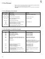
Error Messages . . . . . . . . . . . . . . . . . . . . . . . . . . . . . . . . . . . . . . . . . . .
Error Messages of the Controls . . . . . . . . . . . . . . . . . . . . . . . . . . . . . . . . . . .
Error Messages of the Machine Program . . . . . . . . . . . . . . . . . . . . . . . . . . . . . .
48
48
48
A.
A.1
Appendix . . . . . . . . . . . . . . . . . . . . . . . . . . . . . . . . . . . . . . . . . . . . . . .
Standard Seam Patterns . . . . . . . . . . . . . . . . . . . . . . . . . . . . . . . . . . . . . . .
50
50
1. General
This short description contains important information to the safe, proper and economical use of the new controls generation "DAC" (Dürkopp Adler Control).
Screen displays in this short description
The display of the symbols in the various screens is dependent on the
settings, the subclass and the equipment of the sewing unit.
The screen displays shown in this short description must therefore not
always exactly match the screen shown in the display of the control
unit.
Operator terminal with graphic guidance of the operator
The operator terminal is equipped with a LCD display and a keypad.
The guidance of the operator occurs exclusively via internationally understood symbols. The various symbols are combined into groups within the menu structure of the sewing and testing programs.
The simple operation makes possible short training times.
Ease of programing
The user can combine 99 freely programmable pocket programs with
up to 25 seam patterns.
For the sewing of sequences, 10 pocket sequences are available.
Each pocket sequence can be put together in any desired order out of
a maximum of 6 pocket programs.
With the "angled pocket version" Class 745-28 all practically suitable
angles can be programmed by the operator with the push of a button.
The time consuming adjustment of the corner knives and the inconvenient programming of seam offsets are avoided.
Setting and testing programs
The DAC has integrated the comprehensive MULTITEST testing and
monitoring system.
A microcomputer assumes the control tasks, monitors the sewing
process and displays operator errors and malfunctions.
Error and testing results are shown in the LCD display.
During fault-free functioning the display shows information to the operation and the sewing procedure.
With an operator error or a malfunction the function sequence is interrupted. The display shows the cause through the appropriate error
symbol.
In most cases the error symbol disappears after the cause of the error
is remedied.
In some cases the main switch must be turned off for safety reasons
during the correction of the error.
A part of the error messages is meant only for the maintenance staff.
Special programs aid in making the mechanical settings and make possible a quick checking of the input and output elements without additional measuring devices.
RAM memory card
The RAM memory card serves for the long-term storage of all programmed data.
It can be used to transfer the data to other sewing units.
The controls transmit the data to the memory card.
Stored data can be loaded from the memory card into a DAC control
again.
This procedure can be repeated as often as desired within the life of
the memory card (approx. 4 years).
3
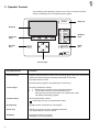
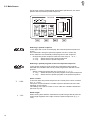
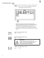
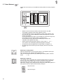
2. Operator Terminal
The entering and displaying of data occurs via an operator terminal
with a LCD display and a comprehensive keypad.
STOP
Stop key
Display
Number
keys
Function
keys
Escape
key
Enter
key
ESC
DURKOPP
ADLER AG
Cursor keys
4
Key/ Key Group
Function
Function keys
Calling up the parameter screens of the sewing programs (from the main screen).
Calling up testing programs (during the display of the logo).
Turning functions on/off.
Exiting testing programs and parameter screens (F1).
Cursor keys
Changing parameter values.
,
: Selecting the symbol for the desired parameter
,
: Turning the function of the parameter on/off,
selecting the previous/next step of the parameter value,
activating the testing program
Numeric keys
Entering parameter values.
: Reversing the sign of the parameter value
Escape key
Displaying the old parameter value again.
Enter key
Calling up screen to set the selected parameter.
The set parameter value is stored.
Stop key
Exiting the machine program.
Stopping the current program.
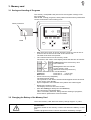
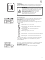
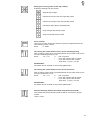
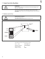
3. Memory card
3.1 Saving and Loading of Programs
The memory card (RAM card) serves for the longterm storage of sewing programs.
With its aid, sewing programs, seam patterns and machine parameters
can be transfered to other sewing units.
Write protection
STOP
Start
Label
ESC
DURKOPP
ADLER AG
–
–
With the main screen as shown insert the memory card in the direction of the arrow into the side of the control unit.
The label must face the operator.
The controls switch into the memory mode.
The arrow in the center of the display shows the direction of transfer:
Loading data from the memory card
to the controls
–
–
–
–
Saving data from the controls
on the memory card
(Observe the write protection!)
Set the desired direction of transmission.
Load data:
Press the "
" cursor key.
Save data:
Press the " " cursor key.
Press function key F4 (Start).
The data transfer starts.
The symbols for the data to be transfered appear above the arrow
in the center of the display.
Upon completion of the transfer all symbols are erased again.
Remove the memory card.
The display returns to the main screen.
After the loading of data press the STOP key.
The controls are initialized again.
This is necessary because, along with the loading of programs,
new machine parameters are also loaded.
3.2 Changing the Battery of the Memory Card
Life of the memory card without a battery change: approx. 4 years
ATTENTION !
Programs saved on the memory card are lost when the battery is changed.
Load the programs into the control unit before the battery change!
5
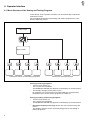
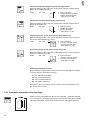
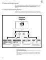
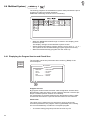
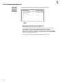
4. Operator Interface
4.1 Menu Structure of the Sewing and Testing Programs
In the design of the operator interface only internationally understood
symbols are used.
The individual parameters and setting and testing programs are combined in different groups.
Turn on the
main switch
Main screen
Parameter menus of the sewing programs
Setting and testing programs
Calling up sewing programs
– Turn the main switch on.
The controls are initialized.
The DÜRKOPP-ADLER logo appears in the display for a short period.
– The display changes to the main screen.
By pressing one of the function keys F1 to F4 the corresponding
parameter menu of the sewing programs is called up.
Calling up setting and testing programs
– Turn the main switch on.
The controls are initialized.
The DÜRKOPP-ADLER logo appears in the display for a short period.
– During the display of the logo press one of the function keys F1
to F4.
The display changes to the corresponding group of the setting or
testing programs.
6
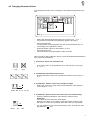
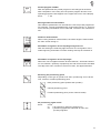
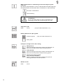
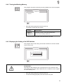
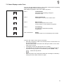
4.2 Changing Parameter Values
The parameter values can be changed in the different parameter screens.
–
–
–
–
Select the desired parameter with the cursor keys " " or " " .
The symbol of the selected parameter appears inversely.
Press the enter key.
The parameter screen appears with the prompt and with the current setting of the parameter value.
Enter parameter value as described in 1. to 4.
Press the enter key.
The new setting of the parameter value is stored.
When changing the parameter values it must be differentiated between
four groups of parameters.
1. Functions, which are turned on/off
–
Turn the function of the parameter on or off with the cursor keys
" " or " ".
(on)
(off)
2. Parameters with different functions
– Set the desired function of the parameter with the cursor keys " "
or " ".
20
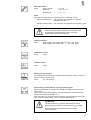
3. Parameters, whose values are changed in steps
– Select the previous or next step of the parameter value with the
cursor keys " " or " ".
Enter: 08, 12, 14, 16, 20
-35
4. Parameters, whose values are entered via the numeric keys
– Enter the desired parameter value with the numeric keys.
Attention!
The value must lie within the fixed limits.
Should a too large or too small a value have been entered, then
the upper or lower limit is display after the enter key is pressed.
– If a sign appears in front of the parameter value, this can be changed with the " " key.
Enter: -99 ... +99
7
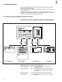
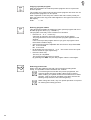
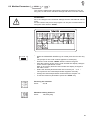
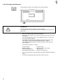
5. Sewing Programs
With the 745-26/28 99 different sewing programs can be combined
with up to 25 seam patterns.
The individual sewing programs (pocket programs) can be freely programmed hereby.
For the sewing of pocket sequences 4 independent sequences are
available. Each individual sequence can be put together in any desired
order out of a maximum of 6 pocket programs.
5.1 Calling Up Sewing Program Parameter Screens
From the main screen it is possible to change to the different parameter screens of the sewing programs with the function keys F1 to F4.
745-26/28
01 03
SAKKO
02
Σ : 0100
1
2
3
4
5
6
GP
PP
PS
SP
745-26/28
745-26/28
1.
2.
3.
4.
Global parameters
GP
Pocket program
PP
01 02 03 04 05 06
02
01
03
04
000
Pocket sequence
PS
Seam patterns
SP
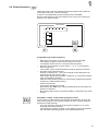
Parameter screens of the sewing programs
Global parameters (GP): Parameters, which are valid for all
pocket programs
Pocket program
(PP): Parameters for programming the seam
run and the associated supplimentary
functions
Pocket sequence
(PS): Programming of pocket sequences
Seam patterns
(SP): Parameters for programming the seam
patterns
8
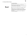
5.2 Starting the Machine Program
–
–
<==== REF
–
–
–
Turn the main switch on.
The controls are initialized.
The DÜRKOPP-ADLER logo appears in the display for a short period.
If, during the display of the logo, one of the function keys
F1 to F4 is pressed, the display switches over to the corresponding
group of the setting or testing programs.
The controls check if the transport carriage is in its rear end position.
If this is not the case the display shows "<==== REF" (reference
run).
Start the reference run by stepping back on the left pedal.
The display changes over to the main screen of the sewing unit.
From the main screen it is possible to change to the various parameter screens of the sewing programs by pressing the function
keys F1 to F4.
The machine program is exited by pressing the "STOP" key.
The controls are initialized.
9
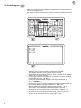
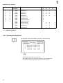
5.3 Main Screen
On the main screen are displayed all important parameters, the seam
pattern and the selected pocket sequence.
745-26/28
01 03
Σ : 0100
GP
01 03
02
02
SAKKO
L : 140
1
2
3
4
5
6
PP
PS
SP
Selecting a pocket sequence
In the upper left corner of the display the selected pocket sequence is
shown.
If the automatic change of pocket programs is active, arrows are
shown between the individual pocket programs of the sequence.
– Change the pocket sequence with the cursor keys " " or " ".
" " key: Select the previous pocket sequence
" " key: Select the next pocket sequence
01 03
02
Selecting a pocket program in the current pocket sequence
In the pocket sequence a bar marks the selected pocket program.
A double bar indicates that in that pocket program the stacker is switched on.
– Select a pocket program with the cursor keys " " or " "
" " key: Select the previous pocket program of the pocket sequence
" " key: Select the next pocket program of the pocket sequence
Σ : 0100
L : 140
10
Piece counter
To the left under the pocket sequence the current piece count is shown
(e.g. "Σ : 0100").
The piece counter shows the number of pieces finished since the last
resetting of the counter.
The setting of the piece counter occurs under the "Global Parameters"
(function key F1).
Seam length
When sewing with distance measurement (without light barrier) the set
seam length appears at the right under the pocket sequence (e.g. "L :
140").
Seam pattern
In the right half of the display the seam pattern of the selected pocket
program is shown.
Above the seam pattern the corresponding program name appears.
SAKKO
ATTENTION !
In order to associate the pocket program with a specific
seam pattern, change to the parameter screen of the
pocket programs (PP) with the function key F2.
There the desired seam
pattern can be accessed with the "
" symbol.
The association of a seam pattern
is not possible via the main screen!
1
2
3
4
5
6
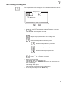
Altering parameters
The six parameters in the lower left half of the display make possible a
quick access to the six most important parameters of the current
pocket program.
They can be altered directly with the numeric keys.
The number of the key to be pressed is shown at the right next to the
parameter symbol.
1: Switching the corner knife on/off
2: Correcting the seam beginning with the light barrier
( seam length )
3: Correcting the seam end with the light barrier
( seam length )
4: Switching the piping knife on/off
5: Correcting the corner knife incision at the seam beginning
6: Correcting the corner knife incision at the seam end
The functions and settings of the individual parameters are described
in more detail in the Chapters 5.4 ("Global Parameters") and 5.5
("Pocket Program").
The function correcting the seam beginning or correcting the seam end
with the light barrier ( seam length ) can be changed to distance
measurement ( Number 2 ).
Description see chapter 5.3.2.
Selecting the function occurs under the "Pocket Program".
11
Correction the seam beginning with the light barrier
With the change of the value the corner knife is drawn onward accordingly at the seam beginning.
Enter:
-99...+99
0 = No correction
+ = Seam beginning earlier
- = Seam beginning later
Step size: 0.1 mm
Correction the seam end with the light barrier
With the change of the value the corner knife is drawn onward accordingly at the seam end.
Enter:
-99...+99
0 = No correction
- = Seam end earlier
+ = Seam end later
Step size: 0.1 mm
Correction of the corner knife on the seam beginning
With the change of the value a fine adjustment of the corner knife incision at the seam beginning occurs.
+
Enter:
-99...+99
0 = No correction
+ = Corner incision earlier
- = Corner incision later
Step size: 0.1 mm
Correction of the corner knife on the seam end
With the change of the value a fine adjustment of the corner knife incision at the seam end occurs.
Enter:
-99...+99
0 = No correction
- = Corner incision earlier
+ = Corner incision later
Step size: 0.1 mm
+
Selecting parameter screens
By pressing the appropriate function key F1 to F4 the display changes
to one of the four parameter screens.
F1:
F2:
F3:
F4:
GP (Global parameter)
PP (Pocket program)
PS (Pocket sequence)
SP (Seam patterns)
By pressing the function key F1 one returns from the parameter screens to the main screen.
5.3.1 Automatic recognition of the flap angle
When the unit is supplied with the kit 0794 002472 , Automatic Detection of Inclination, (auxiliary equipment), the 2nd LED must be activated.
The flap to be sewn, shown on the main screen, will appear dashed.
12
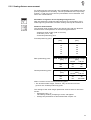
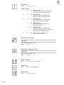
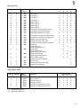
5.3.2 Sewing distance measurement
For measuring the seam length, two possibilities are available.Use the
pocket programme for selecting. The two possibilities are reciprocally
locked, i.e. that only one of the two possibilities can be selected. The
other one is deactivated.
Automatic recognition of the flap beginning and end
With this setting the reflecting light barrier for the recognition of the
seam beginning and seam end when sewing with flap is switched on.
Distance measurement
The shortest seam lengths which can still be sewn with the distance
measurement are dependent on the following parameters:
- Maximum seam length (180 or 220 mm)
- Subclass (-26 or -28)
- Selected positioning point
Forward positioning point:
Needle Clearance Shortest Seam Length
[mm]
[mm]
8
10
12
14
16
20
Rear positioning point:
max. Seam Length Shortest Seam Length
[mm]
[mm]
745-26
745-28
180
220
Central positioning point:
15
20
25
30
35
40
20
60
60
100
Sewing Length Shortest Seam Length
[mm]
[mm]
745-26
745-28
180
220
20
60
20
90-APM *
APM = Position of the central positioning point
* The shortest seam length, however, may not fall short of that
given for the forward positioning point.
The change of the seam length parameter value is done on the main
screen.
– Operate the key " 2 ".
The setting window, prompting to enter, will appear.
– Change the parameter as described under chapter 4.2.
13
5.4 Global Parameters (
)
Global parameters are parameters, which apply for all pocket programs.
Example: If the corner knife is switched off all pockets will be
made without corner knife incisions.
–
–
–
–
With the main screen as shown press function key F1.
The display changes to the screen for the global parameters.
Select the desired parameter with the cursor keys " " or " ".
The symbol of the selected parameter appears inversely.
Change the selected parameter as described in Chapter 4.2.
By pressing the function key F1 the display returns to the main
screen.
Switching the corner knife on/off
Enter:
on/off
Switching the center knife on/off
Enter:
on/off
ATTENTION !
When the center knife is switched off the
corner knives are also automatically switched off.
When the center knife is switched on again,
the corner knives remain switched off.
They must be switched on separately.
Switching the piping knife on/off
Enter:
on/off
14
Setting the closing order of the flap clamps
6 different settings can be chosen:
Without flap clamps
Close first the left, then the right flap clamp
Close first the right, then the left flap clamp
Close both flap clamps simultaniously
Only the right flap clamp exists
Only the left flap clamp exists
Piece counter
The piece counter shows the number of pieces completed since the
last resetting of the counter.
Enter:
0...9999
Correcting the center knife incision at the seam beginning
With a change of the value a fine adjustment of the center knife incision at the seam beginning occurs.
Enter:
-15...+15
0
= No correction
+
= Turn the center knife on earlier
= Turn the center knife on later
Step size: 1 cycle = 0.4 mm
ATTENTION !
An Offset can be entered for the pocket parameters.
Correcting the center knife incision at the seam end
With a change of the value a fine adjustment of the center knife incision at the seam end occurs.
Enter:
-15...+15
0
= No correction
+
= Turn the center knife off earlier
= Turn the center knife off later
Step size: 1 cycle = 0.4 mm
ATTENTION !
An Offset can be entered for the pocket parameters.
Activate working method for breast welt pocket (745-28 A)
The breast welt pocket working method will be connected / disconnected.
Enter: on/off
15
5.5 Pocket Program (
)
Under this menu item are located the parameters for programming the
various pocket programs.
With the aid of the parameters the seam run and the supplimentary functions associated with it are freely programmed.
–
–
–
–
–
–
16
With the main screen as shown press function key F2.
The display changes to the pocket program screen.
By pressing the function key F4 the display changes to the second
screen of the pocket program.
In the upper left line of the display is shown the currently selected
pocket program (e.g. "PP : 01").
If it exists, the associated program name apprears below it
(e.g. "<JACKET>").
In the upper right corner of the display the seam pattern number of
the selected pocket program appears (e.g. "SP : 01").
Select the desired parameter with the cursor keys " " or " ".
The symbol of the selected parameter appears inversely.
Change the selected parameter as described in Chapter 4.2.
By pressing the function key F1 the display returns to the first
screen of the pocket program or to the main screen.
Pocket program number
With this parameter the pocket program to be changed is selected.
After completion of the entry the new pocket program and the corresponding program name appear in the upper left corner of the display.
Enter:
1...99
Sewing distance measurement
Two different possibilities can be selected. Use the pocket programme
for selecting. The two possibilities are reciprocally locked, i.e. that only
one of the two possibilities can be selected. The other one is deactivated.
Distance measurement
When useing distance measurement, the seam length is entered with
the main screen being on.
Automatic recognition of the flap beginning and end
With this setting the reflecting light barrier for the recognition of the
seam beginning and seam end when sewing with flap is switched on.
Automatic recognition of the flap angle
When the unit is supplied with the kit 0794 002472 , Automatic Detection of Inclination, (auxiliary equipment), the 2nd LED must be activated.
The flap to be sewn, shown on the main screen, will appear dashed.
Selecting the positioning point
Depending on the type of goods to be sewn, positioning occurs at the
rear, central or forward positioning point.
Rear positioning point (toward the operator)
Central positioning point
Forward positioning point (to the machine head)
All positioning lights on/off
Enter:
on/off
on
= all positioning lights are switched on
off
= positioning lights are switched as set in the
pocket programm
17
Stitch condensation or bartacking at the seam beginning and
seam end
By changing this parameter a coice is made whether the seam beginning
and seam end are executed with stitch condensation or with bartacking.
with stitch condensation
with bartacking
ATTENTION !
By 1.4 mm stitch length in stitch condensation the
bartacking is sewn with a stitch length of 0.8 mm.
Flap feed on/off
Enter:
on/off
(only bei feed methods B, C, F)
Sewing patterned or plain goods
Patterned goods
(only with feed methods D, F)
Plain goods
Transport carriage return after sewing
Wait position
After the sewing the transport clamps automatically run
back into the wait position without sewing goods.
Feed position
After the sewing the transport clamps automatically run
back into the feed position without sewing goods.
Returm with sewing goods
(only with feed method A)
After the sewing the transport clamps transport the
sewing goods back into the feed area.
Stacker on/off
Enter:
on/off
18
Smoother on/off
Enter:
Active period:
Step size:
Speed level:
t = 5...20
1 cycle = 0.1 s
v = 5...15
Note:
With the smoother there is a dual use of the solenoid valves:
– Stacker switched on: The smoother is triggered as a stacker
supplement (Y63).
– Stacker switched off: The smoother is triggered as an ejector (Y42).
ATTENTION !
If both a stacker and a smoother are available and
no stacking procedure takes place, then both
parameters must be switched off!
Tape feed on/off
Enter:
Tape length at the seam beginning:20...100 [mm]
Tape length at the seam end:
20...100 [mm]
Hold-down on/off
Enter:
on/off
Vacuum on/off
Enter:
on/off
Setting the feed speed
The feed speed, between the loading station and the needle, can be reduced in steps of each 10%.
Enter:
50...100 (100%)
Associating a seam pattern to the pocket program
After this parameter is selected the display changes to the seam pattern screen.
There the selected seam pattern can be changed or a different seam
pattern selected (see Chapter 5.1).
After the return to the main screen (function key F1) the last seam pattern created is associated to the current pocket program.
ATTENTION !
The association of a specific seam pattern with a
pocket program must be made with the " " symbol.
This association is not possible via the main
screen (SP/F4)!
19
Copying a pocket program
With this parameter the selected pocket program can be copied into
another pocket.
The number to be entered shows the pocket program into which the selected pocket program is to be copied.
After completion of the entry the number and name of the pocket program into which the copy was made appears in the upper left corner of
the display.
Enter:
1...99
Entering program names
This parameter enables the labeling of each pocket program with an individual program name (e.g. "JACKET").
The program name may have a maximum of 8 letters.
– Press the " " or " " cursor key.
A window is opened in the lower right corner of the display.
The program name of the current pocket program appears in this
window.
If the current pocket program was not yet given a program name
the window remains empty.
– One moves through the alphabet with the function keys F2 and F3.
F2: move forward
F3: move back
– By pressing the cursor keys " " or " " the cursor moves one position to the left or right respectively.
– Press the enter key.
The entry is completed.
The entered program name is stored.
By pressing the "ESC" key the old program name is used again.
Selecting pedal mode
When using the loading mode with vacuum and/or holding-down
clamp, it is possible to select between two variants.
For selecting this mode with the pocket programme, the
Vacuum and/or the Down-holder clamp must be active.
When loading, the pedal must first be treaded into its basic
position. Then it must be operated once again, before the
feeding clamp travels to the seam beginning.
When using this mode, only one pedal operation is required
for starting the loading process.
20
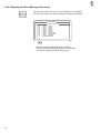
5.6 Pocket Sequence (
)
Under this menu item the individual pocket programs are combined
into sequences which can be called up.
A total of 10 independent pocket sequences are available.
Each pocket sequence can be combined out of up to six pocket programs in any desired order.
745-26/28
1.
2.
3.
4.
01 02 03 04 05 06
02
03
04
Programming a pocket sequence
– With the main screen as shown press the function key F3.
The display changes to the pocket sequence screen.
The display shows the four current pocket sequences.
– Move the cursor with the cursor keys " " or " " to the desired
pocket sequence.
The number of the selected pocket sequence appears inversely.
– Program the pocket sequence.
Enter the numbers (01...99) of the desired pocket programs consecutively with the numeric keys.
With single digit pocket program numbers a "0" must be entered in
front of the desired number.
After the sixth pocket program is entered the programmed pocket
sequence is automatically saved.
– Press the enter key.
The pocket sequence is saved.
By pressing the "ESC" key during programming the old pocket sequence is restored.
– By pressing the function key F1 the display is returned to the main
screen.
Automatic change of the pocket programs on/off
If this function is switched on the controls automatically move to the
next pocket program of the pocket sequence after a pocket program
has been worked through.
– Turn the automatic change of the pocket programs on or off by
pressing the function key F4.
The automatic change is shown in the display by arrows between
the individual pocket programs of the pocket sequences.
21
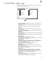
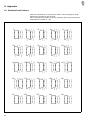
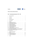
5.7 Seam Patterns (
)
Under this menu item up to 25 different seam patterns can be programmed.
745-26/28
01
000
–
–
–
–
–
With the main screen as shown press the function key F4.
The display changes to the seam pattern screen.
Three parameters for the programming of the seam pattern number, the flap side and an additional seam offset appear in the left
third of the display.
In the windows in the center of the display are shown the flap form
(left window) and the seam pattern (right window).
In the window in the right third of the display is shown the
complete seam pattern with flap.
Select the desired parameter with the cursor keys " " or " ".
The symbol of the selected parameter appears inversely.
Change the selected parameter as described in Chapter 4.2.
By pressing the function key F1 the display returns to the main
screen.
Selecting a seam pattern
After the initialization of the program memory 25 standard seam patterns are filed in the controls (see Appendix A1).
They can be called up directly by entering the seam pattern number.
Enter:
1...25
Selecting a flap side
The sewing unit is equipped with a reflected light barrier for the recognition of the seam beginning and seam end when sewing with flap.
The parameter shows the side on which the flap is positioned.
With the a change of the parameter the flap side of the seam pattern in
the right third of the display automatically changes.
flap at the left
flap at the right
22
Additional seam offset
Enter:
0...20 [mm]
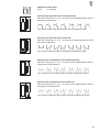
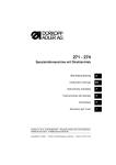
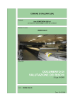
Selecting the flap form at the seam beginning
With the cursor keys " " or " " a choice can be made between the following seven flap forms:
The numbers above the flap forms denote the different angles.
Selecting the flap form at the seam end
With the cursor keys " " or " " a coice can be made between the following seven flap forms:
The numbers under the flap forms denote the different angles.
Selecting the seam pattern at the seam beginning
With the cursor keys " " or " " a choice can be made between the following seven seam patterns:
The numbers over the seam patterns denote the different angles.
Selecting the seam pattern at the seam end
With the cursor keys " " or " " a choice can be made between the following seven seam patterns:
The numbers under the seam patterns denote the different angles.
23
6. Setting and Testing Programs
The machine software encompasses different machine-specific setting
and testing programs and the well-known Multitest system.
A terminal selftest checks the individual components of the operator
terminal.
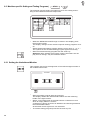
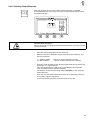
6.1 Calling Up Setting and Testing Programs
After the sewing unit is turned on one can change over to the different
groups of setting and testing programs with the function keys F1 to F4.
Turn the
main switch on
Dürkopp Adler AG
745-26/28
05.05.95
Selftest
RAM
F Keyboard
EPROM
F Interface
F RAM-Card
List
Machine Parameters
Machine-specific
Setting and Testing
Programs
–
–
24
Multitest System
Display
Exit
Terminal Selftest
(only for service staff)
Turn the main switch on.
The controls are initialized.
The DÜRKOPP-ADLER logo appears in the display for a short period.
While the logo is visible press one of the function keys F1 to F4.
The display changes to the corresponding group of setting and testing programs.
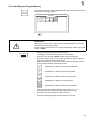
6.2 Machine Parameters (
STOP
+
)
The machine parameters describe the technical execution of the sewing unit, as well as the machine settings and their correction values.
ATTENTION !
As a rule changes in the machine settings result in mechanical conversions.
For this reason this part of the program can only be accessed after entering the code number "25483".
Code
–
–
–
–
–
–
While the DÜRKOPP-ADLER logo is visible press the function key
F1.
The prompt for the code number appears in the display.
Enter the code number "25483" with the numeric keypad.
After the entering of the correct code number the display changes
to the machine parameter screen.
With an incorrectly entered code number the display changes to
the main screen.
Select the desired parameter with the cursor keys " " or " ".
The symbol for the selected parameter appears inversely.
Change the selected parameter as described in Chapter 4.2.
To exit the machine parameters press the "STOP" key.
Selecting the subclass
Enter:
26, 28
Maximum sewing distance
Enter:
180, 220 [mm]
25
Feed device
Enter:
A, B, C, D, F, H
745-26 745-28
X
A:
Piped pockets,
manual positioning of the piping strip,
flap and other supplimentary parts
X
X
B:
Piped pockets,
automatic feed of the piping strip,
without cutting of the piping ends
X
X
C:
Piped pockets,
automatic feed of the piping strip,
with cutting of the piping ends
X
D:
Breast pockets,
automatic feed and aligning of
the breast selvage
X
F:
Piped pockets,
automatic feed of the piping strip,
automatic feed and aligning of the flap,
with cutting of the piping ends
X
H:
Sewing in of the sewing unit
(only for service staff)
X
Activating the smoother
This parameter signals the controls if the sewing unit is equipped with
a smoother.
The smoother is turned on and off in the main screen under the menu
item "Pocket Program" (F2).
Enter:
on/off
Switching the tape feed on/off
This parameter signals the controls if the sewing unit is equipped with
a tape feed.
The tape feed is turned on and off in the main screen under the menu
item "Pocket Program" (F2).
Enter:
on/off
Needle clearance
Enter:
8, 10 , 12, 14, 16, 20 [mm]
Sewing rpm
Enter:
2500, 2750, 3000 [rpm]
Stitch length
Enter:
2.55, 3.10 [mm]
26
Stitch length in the stitch condensation
Enter:
0.50, 0.80, 1.40 [mm]
Number of stitches in the stitch condensation
Enter:
5...10 [stitches]
Switching the thread monitors on/off
With this parameter the needle thread and underthread monitors are
switched on and off.
Enter:
on/off
Displays:
Needle thread breakage:
Underthread bobbin empty:
The empty bobbin blinks.
Clearance of the rear positioning point to the central positioning
point
Enter:
40...120 [mm]
Switching the remover on/off
This parameter signals the controls if the sewing unit is equipped with
a remover.
The remover is turned on and off in the main screen under the menu
item "Pocket Program" (F2).
Enter:
on/off
Switching the stacker on/off
This parameter signals the controls if the sewing unit is equipped with
a stacker.
The stacker is turned on and off in the main screen under the menu
item "Pocket Program" (F2).
Enter:
on/off
27
6.3 Machine-specific Setting and Testing Programs (
STOP
+
)
The machine-specific testing programs serve for the setting and testing of the individual machine components.
–
–
–
While the DÜRKOPP-ADLER logo is visible in the display press
the function key F2.
The display changes to the machine-specific testing programs screen.
Select the desired testing program with the cursor keys " " or " ".
The symbol for the selected testing program appears inversely.
Start the selected testing program with the enter key.
Attention! After starting the program "Testing smoother" the display did not change, only the smoother works.
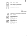
6.3.1 Setting the Underthread Monitor
This program serves for the alignment of the reflected light barriers of
the underthread monitor.
745-26/28
–
–
–
28
Start the testing program with the enter key.
The display shows two underthread bobbins and the reflecting
heads of the light barriers.
With a correct alignment of the light barriers a reflection occurs
when an empty bobbin is turned.
A reflection is shown by an arrow between the reflecting head and
the underthread bobbin.
At the same time a signal tone can be heard.
To exit the testing program press the function key F1.
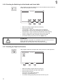
6.3.2 Initializing the Program Memory
The program serves to load a standardized factory setting for the parameters of the sewing programs.
745-26/28
ATTENTION !
After starting one of the four programs a standardized factory setting
will overwrite the set parameters!
For this reason the program can only be started after entering the code
number "25483".
Code
–
–
–
Start the testing program with the enter key.
The display shows the prompt for the code number.
Enter the code number "25483" with the numeric keypad.
After the entering of the correct code number the display changes
to the five parameters described below.
After the entering of an incorrect code number the display returns
to the machine-specific parameter screen.
Initialization of defective machine parameters
Initialization of defective pocket programs
Initialization of defective pocket sequences
Initialization of defective seam patterns
Initialization of all programs and parameters
–
–
–
Select the desired program with the cursor keys " " or " ".
The symbol for the selected program appears inversely.
Start the selected program with the enter key.
To exit the testing program press the function key F1.
29
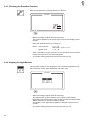
6.3.3 Checking the Smoother Function
With this program the smoother function is tested.
745-26/28
20
15
–
–
Start the testing program with the enter key.
The symbol appears in the lower right corner of the display with a
prompt.
Enter the desired values for "t" and "v".
Enter: Active period:
Speed level:
–
–
t = 5...20
Step size:1 cycle = 0.1 s
v = 5...15
After confirmation of the value for "v" the smoother runs for the selected active period at the selected speed.
To exit the testing program press the function key F1.
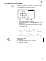
6.3.4 Aligning the Light Barriers
The program serves for the alignment of the reflected light barrier for
the recognition of the seam beginning and seam end.
745-26/28
–
–
–
30
Start the testing program with the enter key.
Two light barrier symbols appear in the center of the display.
Manually push the transport clamp under the reflected light barrier.
With a reflection an acoustic signal is heard.
The display of the light barrier symbols changes from inverse to
normal.
To exit the testing program press the function key F1.
6.3.5 Setting the Corner Knife Adjustment
With this program the corner knife clearance and the angle of the corner knife can be set.
The minimum and maximum corner knife clearances are dependent on
the subclass and the equipment of the sewing unit.
745-26/28
–
–
–
Start the testing program with the enter key.
Set the maximum or minimum corner knife clearance with the cursor keys " " or " ".
Set the angle of the corner knife with the function keys F3 (corner
knife seam beginning) and F4 (corner knife seam end).
The seam beginning and seam end each have a choice of seven
angle settings available.
Corner knife seam beginning (F3):
Corner knife seam end (F4):
Caution Risk of Injury !
Danger of cuts!
Do not reach into the area of the rising corner knives.
–
–
–
Press the " " cursor key.
The corner knives rise.
Press the " " cursor key.
The corner knives lower again.
To exit the testing program press the function key F1.
31
6.3.6 Checking the Switching-in of the Needle and Center Knife
This program checks the switching-in of the needles and the center knife with the sewing drive running.
745-26/28
–
–
–
–
–
Start the testing program with the enter key.
Press function key F2.
1st operation: Start of the sewing drive at 1000 rpm
2nd operation: Running the sewing drive at 3000 U/min
3rd operation: Stop in position 2 (thread lever high position)
Turn the center knife on and off with the function key F3.
Turn the needles on and off with the function key F4.
To exit the testing program press the "STOP" key.
ATTENTION !
Before exiting the program it is essential to let the machine head run
briefly with the needles and center knife turned off.
Otherwise the next seam will not be executed correctly.
6.3.7 Checking the Tape Feed Function
This program tests the transport and cutting function of the tape feed.
745-26/28
ON
–
–
–
–
32
OFF
Start the testing program with the enter key.
Press function key F2. The tape feed starts.
Press function key F3.
The motor of the tape feeds stops.
The tape is automatically cut.
To exit the testing program press the function key F1.
6.3.8 Checking the Catch-folder without Transport Clamp
This program tests the function of the catch-folder.
The transport clamps remain in their rear end position hereby.
745-26/28
–
–
–
–
Start the testing program with the enter key.
Press function key F3.
The catch-folder swings into the vertical position and lowers onto
the material slide plate.
Press function key F2.
The catch-folder rises and swings over the feed board.
To exit the testing program press the "STOP" key.
6.3.9 Checking the Feed Procedure with Transport Clamp
This program serves for testing the feed procedure.
745-26/28
–
–
–
–
–
–
–
Start the testing program with the enter key.
A reference run is conducted.
Step on the pedal.
The transport carriage runs to the feed station.
The feed procedure is run through as in a sewing program.
After operation of the last stage an arrow appears in the display.
Run the transport carriage into the rear position by stepping on the
pedal in tapping operation.
In this position the transport carriage waits until the pedal is at rest.
The transport clamps rise and the flap clamps open.
The program is restarted by stepping on the pedal.
To exit the testing program press the "STOP" key.
33
6.4 Multitest System (
STOP
+
)
The testing programs of the Multitest system make possible the quick
checking of input and output elements.
Additional measuring devices are not necessary.
–
–
–
While the DÜRKOPP-ADLER logo is visible in the display press
function key F3.
The display changes to the Multitest system screen.
Select the desired testing program with the cursor keys " " or " ".
The symbol for the selected testing program appears inversely.
Start the selected testing program with the enter key.
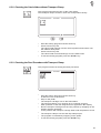
6.4.1 Displaying the Program Version and Check Sum
The program checks the permanent store memory (ROM) of the
microcomputer.
MULTITEST
EPROM-Test
ROM-Size
Class
Version
Date
Checksumme
:
:
:
:
:
192k EPROM
745-26/28
745A01
19.06.95
0x64AE
Program version
By program versions with the same class designation and the same
identification letter the higher version replaces all lower versions (Example: 745A03 replaces 745A01 and 745A02).
If a replacement is possible although the identification letter is different this will be noted in a special communication to the customer.
Check sum
The check sum is meant only for the factory service personnel.
It shows specialists if the program memory (EPROM) of the sewing
unit controls flawlessly contains the complete program.
–
34
To exit the testing program press the function key F1.
6.4.2 Testing the Working Memory
The program checks the working memory (RAM) of the microcomputer.
MULTITEST
RAM-Test
RAM OK
–
–
Start the testing program with the enter key.
The display shows the test results.
Display
Explanation
RAM OK
RAM-Error
Working memory functioning flawlessly
Error in the working memory
To exit the testing program press the function key F1.
6.4.3 Displaying the Setting of the DIP Switches
The program shows the setting of the DIP switches on the CPU board
of the control unit.
MULTITEST
DIP-Switch
1 2 3 4 5 6 7 8
ON
OFF
ATTENTION !
Currently the DIP switches are not employed on any machine class.
The setting of the various DIP switches has no influence on the operation of the sewing unit.
–
–
Start the testing program with the enter key.
To exit the testing program press the function key F1.
35
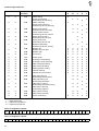
6.4.4 Selecting Input Elements
The program serves for the setting of the input elements.
MULTITEST
Input-Select
S?
Input-Nr. :
ATTENTION !
All input elements were carefully set at the factory.
The setting and correction may only be conducted by trained service
personnel.
–
–
–
Start the testing program with the enter key.
Enter the code number of the desired input element with the numeric keypad.
The short designations of the circuit diagram serve as code numbers (see following table).
The display shows the wiring diagram designation and the switching status of the selected input element (e.g. "+S17").
The display changes when the switching status of the input element changes.
The switching status "+" means:
Contact switch
Proximity switch
Reflected light barrier
Continuous beam barrier
–
–
36
=
=
=
=
Contact open
Metal in front of the switch
No reflection
Beam not interrupted
Set the input element until the display shows the desired switching
status.
To exit the testing program press the function key F1.
Input elements
745-26 745-28
X
X
X
X
X
X
X
X
X
X
X
X
X
X
X
X
X
X
X
X
X
X
X
X
X
X
X
X
X
X
X
X
X
X
X
X
X
X
X
X
X
X
X
X
X
X
Input
element
S01
S02
S03
S04
S05
S06
S07
S08
S09
S10
S11
S15
S17
S18
S23
S25
S26
S27
S28
S29
S30
S31
S32
Function
A
Left pedal 1
Left pedal 2
Left pedal 3
Left pedal 4
Right pedal 1
Right pedal 2
Right pedal 3
Right pedal 4
Limit switch Knife bracket forward
Limit switch Knife bracket back
Knife bracket Reference point
Limit switch Transport carriage forward
Limit switch Transport carriage back
Needle thread monitor left
Needle thread monitor right
Transport carriage Reference position
Folder up
Catch-folder up
Positioning device up
Folder down
Catch-folder down
Positioning device down
Catch-folder swung
Positioning device swung
Catch-folder vertical
Positioning device vertical
Flap seat up
Pocket bag placement tilted
Pocket bag feed down
X
X
X
X
X
X
X
X
X
X
X
X
X
X
X
X
Feed method
B
C
D
X
X
X
X
X
X
X
X
X
X
X
X
X
X
X
X
X
X
X
X
X
X
X
X
X
X
X
X
X
X
X
X
X
X
X
X
X
X
X
X
X
X
X
X
X
X
X
X
X
X
X
F
X
X
X
X
X
X
X
X
X
X
X
X
X
X
X
X
X
X
X
X
X
X
X
X
X
X
X
X
X
X
X
O
O
O
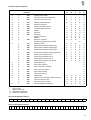
Light barrier inputs
745-26 745-28
X
X
X
X
X
X
X
X
X
Input
element
S100
S101
S104
S106
S107
Function
A
Flap scanning 1
Flap scanning 2
Stacking control
Remaining thread monitor left
Remaining thread monitor right
X
O
X
X
X
Feed method
B
C
D
X
O
X
X
X
X
O
X
X
X
X
O
X
X
X
F
X
O
X
X
X
X = Stanard equipment
O = Optional equipment
37
6.4.5 Checking Input Elements
The program serves for the testing of the input elements.
MULTITEST
Input-Test
S26
–
–
–
–
38
:
Start the testing program with the enter key.
Operate the input element to be tested.
The display shows the wiring diagram designation and the switching status of the selected input element (e.g. "+S17").
The display changes if the switching status is changed or some
other input element is changed. A change of the switching status is
shown by an acoustic signal.
To exit the testing program press the function key F1.
6.4.6 Selecting Output Elements
With the program the function of the output elements is checked.
It is possible to test one (single-mode) or several (multi-mode) output
elements at a time.
Caution Risk of Injury !
During the function testing of the output elements do not reach into the
running machine.
–
–
Start the testing program with the enter key.
Make the selection between single-mode and multi-mode by the
ten-key keyboard.
1 = SINGLE-Mode
2 = MULTI-Mode
–
–
–
–
Only one output element is tested.
A group of output elements are tested.
Enter the code number of the desired output element by the key F2
(forwards) or F3 (backwards).
The code designations used in the circuit diagram are used as
code numbers (see the following tables).
The display shows the switching status (ON/OFF) of the selected
output element.
Turn the selected output element on and off by pressing the function key F4 in tapping operation.
To exit the testing program press the function key F1.
39
Inside output elements
745-26 745-28
X
X
X
X
X
X
X
X
X
X
Output
element
Y01
Y02
Y03
Y04
Y05
X
X
/Y06
X
X
Y07
X
Y08
X
X
X
X
X
X
X
X
X
X
X
Y09
Y10
Y11
Y12
Y13
Y14
Y15
Y16
Y17
Y18
Y19
X
X
X
X
X
X
X
X
X
X
X
X
X
X
X
X
X
X
X
X
X
X
X
/Y20
Y21
Y22
Y23
Y24
/Y99
Function
A
Folder lifting
Catch-folder lifting
Positioning device lifting
Folder lowering
Catch-folder lowering
Positioning device lowering
Catch-folder swing
Positioning device swing
Catch-folder vertical
Positioning device vertical
Piping knife forward
Positioning device right
Piping knife back
Positioning device left
Needles spreading
Positioning device closing
Needle left
Needle left and right
Needle right
Link swing
Center knife
Transport clamp lifting
Transport clamp lowering
Flap clamp right lifting
Flap clamp left lifting
Folding plates closing
Thread drawing
Thread tension release
Flap feed swing in
Pocket bag feed forward
Flap feed swing out
Pocket bag feed back
Flap feed L closing
Pocket bag placement lifting
Flap feed L opening
Pocket bag gripping
Flap feed R closing
Flap feed R opening
Cover monitoring
Feed method
B
C
D
F
X
X
X
X
X
X
X
X
X
X
X
X
X
X
X
X
X
X
X
X
X
X
X
X
X
X
X
X
X
X
X
X
X
X
X
X
X
X
X
X
X
X
X
X
X
X
X
O
X
X
X
X
X
X
X
X
X
X
X
X
X
O
X
X
X
X
X
X
X
X
X
X
X
X
X
X
X
X
X
X
X
X
X
X
X
X
X
X
X
O
O
O
X
O
O
O
X
O
O
O
X
O
X
O
O
X
O
O
X
X
X
X
X
/ = Open when idle
X = Standard equipment
O = Optional equipment
Valve arrangement 745-26:
Y99 Y24 Y23 Y22 Y21 Y20 Y19 Y16 Y15 Y14 Y13 Y12
Y7
Y6
Y5
Y4
Y3
Y2
Y1
Y17 Y18 Y11 Y10
Y8
Y1 Y17 Y18 Y11 Y10 Y9
Y8
Valve arrangement 745-28:
Y99 Y24 Y23 Y22 Y21 Y20 Y19 Y16 Y15 Y14 Y13 Y12 Y7
40
Y6
Y5
Y4
Y3
Y2
Outside output elements
745-26 745-28
X
X
X
X
X
X
X
X
X
X
X
X
X
X
X
X
X
X
X
X
Y33
Y34
Y35
*Y36
*Y37
Y38
Y39
Y40
Y41
Y42
X
X
X
X
Y43
X
X
X
X
X
X
X
X
X
X
X
X
X
X
X
X
X
X
X
X
X
X
X
X
X
X
X
X
X
X
*
/
X
O
Output
element
=
=
=
=
Function
A
Stopper Flap feed L
Corner knife Seam beginning
Corner knife Seam end
Blower Reflecting foils
Blower Flap feed
Sewing threads cutting
Thread clamp opening
Holder
Vacuum
Stacking
Ejector lowering
Blower
Remover forward
Pocket bag feed press forward
Remover back
Knife bracket Seam beginning 1
Knife bracket Seam beginning 2
Knife bracket Seam beginning 3
Knife bracket Seam beginning swing
Knife bracket Seam end 1
Knife bracket Seam end 2
Knife bracket Seam end 3
Knife bracket seam end swing
Flap seat lifting
Flap seat lowering
Flap seat swing forward
Flap seat swing back
Flap seat opening
Flap seat closing
Tape brake
Tape scissors (directly at the scissors)
Corner knife lock left
Corner knife lock right
Stacker addition lowering
Y44
Y45
Y46
Y47
Y48
Y49
Y50
Y51
Y52
/Y53
Y54
Y55
/Y56
Y57
Y58
/Y59
Y60
Y61
Y62
Y63
X
X
X
X
X
O
O
X
X
X
O
Feed method
B
C
D
X
X
X
O
X
X
O
O
X
X
X
O
X
X
X
O
X
X
O
O
X
X
X
O
X
X
X
X
X
O
O
X
X
X
F
X
X
X
X
O
X
X
O
O
X
X
X
O
O
O
X
X
X
X
X
X
X
X
O
X
X
X
X
X
X
X
X
O
X
X
X
X
X
X
X
X
X
X
X
X
X
X
X
X
O
O
O
O
O
O
O
O
O
O
O
O
O
O
O
O
O
O
O
O
O
X
X
X
X
X
X
X
X
X
X
X
X
X
X
O
O
O
O
O
Y58
Y59
Y60
Y36
Y37
Oil-free air
Open when idle
Standard equipment
Optional equipment
Valve arrangement 745-26:
Y34
Y35
Y38
Y39
Y40
Y41
Y42
Y43
Y44
Y53
Y54
Y55
Y56
Y57
Valve arrangement 745-28:
Y34 Y35 Y38 Y39 Y42 Y45 Y46 Y47 Y48 Y49 Y50 Y51 Y52 Y40 Y41 Y43 Y44 Y53 Y54 Y55 Y56 Y57 Y58 Y33 Y59 Y60 Y61 Y62 Y36 Y37
41
Supplimentary outputs
745-26 745-28
X
X
X
X
X
X
X
X
X
X
X
X
X
X
X
X
Output
element
Y100
Y101
Y102
Y103
Y104
Y105
Y106
Y107
Y104
Y105
Y106
Y107
Function
A
Smoother 0
Smoother 1
Smoother 2
Smoother 3
Lamp back A1
Lamp back A2
Lamp forward A1
Lamp forward A2
Lamp forward 1
Lamp forward 2
Lamp back 1
Lamp back 2
O
O
O
O
X
X
X
X
Feed method
B
C
D
O
O
O
O
O
O
O
O
O
O
O
O
X
X
X
X
X
X
X
X
X
X
X
X
X = Standard equipment
O = Optional equipment
6.4.7 Checking the Step Drives
The program shows the software version of the step drives.
Steppermotor-Test
Software-Version
SMC Version-Nr
1
2
3
4
5
6
–
–
42
Checksum Status
SMC A0 1 M 0 x 3 CB B
SMC A0 1 S 0 x 6 9 B 0
SMC A0 1 S 0 x 6 9 B 0
F
0x 00
0x 40
0x 40
Start the program with the enter key.
The display shows the software versions of the step drives.
To exit the testing program press the function key F1.
6.4.8 Checking the Sewing Drive
The program serves for the testing of the needle positions and the different rpm levels of the sewing drive.
Sewingdrive-Test
AB85A.B0
START
–
–
–
STOP
Start the testing program with the enter key.
Select the symbol of the desired parameter with the cursor keys
" " or " ".
The selected symbol appears inversely.
Set the parameter with the cursor keys " " or " ".
Display the program version of the sewing drive
Sewing drive runs at the selected rpm,
machine head positions in the set position
Machine head positions in position 2
Machine head positions in position 1
Machine head stops unpositioned
Selecting motor rpm
Enter:
70...maximum rpm [rpm]
–
–
–
Press function key F2.
The sewing drive runs at the set rpm.
The current rpm (e.g. "0199 rpm") appears in the upper right corner of the display.
Press function key F3.
The sewing drive stops.
The machine head positions in the set position.
To exit the program press the "STOP" key.
43
6.4.9 Displaying the Error Messages Generated
The program shows the last 10 error messages in the display.
The error messages and their meaning are listed in Chapter 8.
MULTITEST
error messages
01.
02.
03.
04.
05.
06.
07.
08.
09.
10.
–
–
44
->
->
->
->
->
->
->
->
->
->
Error 902/-8
Error 902/-8
Error 902/-8
Error 902/-8
Error 902/-8
Error 902/-8
Error 903/-22358
Error 903/-22358
Error 959/201
EXTERN STOP
Start the testing program with the enter key.
The last 10 error messages appear in the display.
To exit the program press function key F1.
6.5 Terminal Selftest (
STOP
+
)
With the terminal selftest service personnel check the individual components of the operator terminal.
Selftest
RAM
F Keyboard
EPROM
F Interface
F RAM-Card
Display
List
–
While the DÜRKOPP-ADLER logo is shown in the display press
the function key F4.
The terminal selftest runs through the following test programs consecutively.
The testing procedures are shown in the display by run bars.
–
RAM test
The RAM test checks the working memory ("Video RAM") of the
operator terminal.
After completion of the RAM test the terminal selftest automatically
changes to the EPROM test.
EPROM test
The EPROM test checks the program memory ("Program Memory")
of the control unit.
By pressing the function key F2 the terminal selftest continues with
the RAM card test.
RAM card test
The RAM card test checks the memory card.
After completion of the RAM card test the terminal selftest automatically changes the keyboard test.
Keyboard test
The keyboard test checks the keypad of the operator terminal.
After pressing any key a checkmark appears in the display behind
this key by faultfree functioning.
By pressing the "ESC" key the keyboard test is ended.
The display changes to the interface test.
Interface test
The interface test checks the interface of the operator terminal
(special cable required!).
After completion of the interface test the terminal selftest automatically changes to the display test.
Display test
The display test shows the available character set ("Character
Set") and the graphics characters ("Graphic") of the display.
By pressing the function key F2 the display changes to the main
screen of the terminal selftest (see illustration).
Main screen
From the main screen a complete Test Protocol can be called up
with the function key F2.
To exit the terminal selftest press the "STOP" key.
–
–
–
–
–
–
45
7. Output Card of the Step Motor
ATTENTION !
Before starting operation it is essential to check the settings of the
step motor output card.
The step motor output is to be found at the right under the table.
After removing the metal cover the setting elements shown below are
accessable.
7.1 Switches on the Front
Caution Electric Current !
Turn the main switch off.
The switches may not be adjusted carrying current.
Step motor
output
LED 1
LED 2
LED 3
LED 4
Voltage
convertor
Parameter
switches
Current
selector
The switches must be in the positions shown!
LED 1 - LED 4
Parameter switches
Current selector
Voltage convertor
46
see Chapter 7.2
see illustration
F
230 V
7.2 Status Displays on the Front
The four red light diodes (LEDs) on the output card show the operating
status and malfunctions of the step motor.
With flawless operation none of the LEDs may be lit.
LED 1
Undervoltage
Shortfall in the operating voltage of
more than 30%
LED 2
Phase monitoring
Interruption in one or more motor wires
LED 3
Short circuit
Short circuit between two or more
motor phases or motor phase and ground
LED 4
Overheating
Exceeding the allowable operating
temperature
LED 1 and LED 2
Reset
ENABLE input is not activated by the controls
A fault in the output card is shown as follows:
– After the recognition of the error the step motor is turned off for safety reasons (Reset).
For this reason LED 1 and LED 2 are always lit after an error message of the controls.
– The display shows the appropriate error number.
– The statuses of the output card can only be called up with the appropriate testing program of the Multitest system (STOP + F3).
Check the step drives
–
After correction of the fault the malfunction message is cleared by
turning the main switch off and on again.
47
8. Error Messages
With an error in the control system or in the machine program the display shows the corresponding error number.
With the aid of the following tables the error cause can be found and
remedied.
8.1 Error Messages of the Controls
Error number
Explanation
Remedy
Undervoltage
Processor fault
Stabilize the voltage supply
---
External stop input operated
Close the cover hood
300 - 399
Error in the data transmission
to the sewing drive
Check the cable
400 - 411
General step motor fault
---
Output fault AMP1 error (Sewing goods)
Output fault AMP2 error (Knife)
Output fault AMP3 error (Tape)
see Chapter 7.2
-----
Error in the step motor card during the
acknowledgement ( Time Out )
---
100
101 - 199
EXTERN STOP
412
413
414
418 - 420
8.2 Error Messages of the Machine Program
Error number
Explanation
Remedy
700
701
702
703
704
Catch-folder not up
Catch-folder not vertical
Catch-folder not swung
Positioning device not up
Folder not down
Correct
Correct
Correct
Correct
Correct
720
721
Light barrier error at the seam beginning
Refecting foil at the seam beginning not recognized
Replace the refecting foil
Replace the refecting foil
722
Safety stop
Flap outside of seam area or
the missing connection of the 2nd light
barrier for the detection of inclination or
for activating the pocket program.
723
Jumper J308 at the step motor
controller not plugged
Jumper J309 at the step motor
controller not plugged
Plug in jumper J308
(see sketch pg. 49)
Plug in jumper J309
(see sketch pg. 49)
with flap seat and transport carriage
in the feed position
carriage return with sewing goods set to
work procedure B - H
Carriage return in the wait position
Error in the moving of the knife transport
Check the knife drive
724
730
731
740 - 742
48
the
the
the
the
the
setting
setting
setting
setting
setting
Reset the carriage return or feed
device
Error number
Explanation
Remedy
745
Step motor main axle has not
reached the rear limit switch (S17)
Check the sewing goods transport and
limit switch
746
Step motor main axle has not left the
forward limit switch (S15) after 100 ms
Check the sewing goods transport and
limit switch
748
Step motor main axle has run past the
forward limit switch (S15)
Check the sewing goods transport and
limit switch
749
Step motor main axle has run past the
rear limit switch (S17)
Check the sewing goods transport and
limit switch
900
Check sum error in the machine
parameters
Reinitialize the defective machine parameters (see Chapter 6.3.2)
901
Check sum error in the pocket sequences
Reinitialize the defective pocket sequences (see Chapter 6.3.2)
902
Check sum error in the pocket
programs
Reinitialize the defective pocket programs (see Chapter 6.3.2)
903
Check sum error in the seam patterns
Reinitialize the defective seam patterns
(see Chapter 6.3.2)
Error in reading or writing on the
memory card
Repeat the operation,
Switch off the write protection on the card,
Replace the card battery
910 - 991
Jumper on the Step Motor Controller
49
A. Appendix
A.1 Standard Seam Patterns
After the initialization of the program memory the following 25 seam
patterns are present in the controls.
The individual seam patterns can be called up directly by entering the
seam pattern number (1...25).
50
1)
2)
3)
4)
5)
6)
7)
8)
9)
10)
11)
12)
13)
14)
15)
16)
17)
18)
19)
20)
21)
22)
23)
24)
25)