1
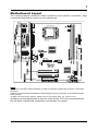
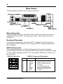
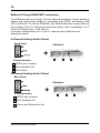
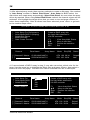
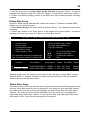
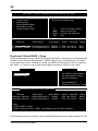
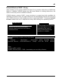
1
Electronic Emission Notices
Federal Communications Commission (FCC) Statement
This equipment has been tested and found to comply with the limits for a Class B digital
device, pursuant to Part 15 of FCC Rules. These limits are designed to provide reasonable
protection against harmful interference in a residential installation. This equipment
generates, uses and can radiate radio frequency energy and, if not installed and used in
accordance with instructions contained in this manual, may cause harmful interference
to radio and television communications. However, there is no guarantee that interference
will not occur in a particular installation.
If this equipment does cause harmful interference to radio or television reception, which
can be determined by turning the equipment off and on, the user is encouraged to try to
correct the interference by one or more of the following measures:
-
REORIENT OR RELOCATE THE RECEIVING ANTENNA
INCREASE THE SEPARATION BETWEEN THE EQUIPMENT AND THE RECEIVER
CONNECT THE EQUIPMENT INTO AN OUTLET ON A CIRCUIT DIFFERENT FROM
THAT OF THE RECEIVER
CONSULT THE DEALER OR AN EXPERIENCED AUDIO/TELEVISION TECHNICIAN
NOTE: Connecting this device to peripheral devices that do not comply with Class B
requirements, or using an unshielded peripheral data cable, could also result in
harmful interference to radio or television reception.
The user is cautioned that any changes or modifications not expressly approved
by the party responsible for compliance could void the user’s authority to operate
this equipment.
To ensure that the use of this product does not contribute to interference, it is
necessary to use shielded I/O cables.
Copyright
This manual is copyrighted with all rights reserved. No portion of this manual may be
copied or reproduced by any means.
While every precaution has been taken in the preparation of this manual, no responsibility
for errors or omissions is assumed. Neither is any liability assumed for damages resulting
from the use of the information contained herein.
Trademarks
All brand names, logos and registered trademarks mentioned are property of their
respective owners.
2
Table of Contents
HARDWARE CONFIGURATION ....................................................... 4
Key Features ............................................................................................... 4
MOTHERBOARD LAYOUT ................................................................ 7
REAR PANEL .................................................................................... 8
AUDIO CONFIGURATION ................................................................ 10
SPEAKER CONFIGURATION ............................................................ 10
Method 1: 4/6 Surround audio output of back panel only ........................... 10
Method 2: Using S-Bracket connectors ...................................................... 12
S-Bracket(SPDIF)/CEN/LFE/Surround Output Connector- CN6(optional)...13
Front Panel Audio Header - FPS1 ............................................................... 15
CD-IN Connector - CDS1 ............................................................................ 16
JUMPER SETTING ............................................................................ 17
JBAT1 - CMOS Clear ................................................................................... 17
J2, J3 - CPU Frequency Select Jumper ...................................................... 17
CONNECTORS ................................................................................. 18
Floppy Disk Drive Connector - CN3 ............................................................ 18
Hard Disk Connectors - CN1, CN2 ............................................................. 18
Serial ATA Hard Disk Connectors - SATA-1, SATA-2 .................................... 19
USB Connectors - USB1, USB2 ................................................................. 21
Fan Power Connectors - CPU FAN, SYS FAN ............................................. 22
Front Panel Header - FP1 ........................................................................... 23
SLOTS .............................................................................................. 24
CPU INSTALLATION ........................................................................ 25
Technical Reference Booklet
3
INSTALL DDRII DIMMS ................................................................... 29
BIOS SETUP ..................................................................................... 30
About the Setup Utility .................................................................................. 30
The Standard Configuration ........................................................................ 30
Entering the Setup Utility ............................................................................. 30
Main Menu ................................................................................................... 31
Standard CMOS Features ........................................................................... 32
Advanced BIOS Features ............................................................................ 33
Advanced Chipset Features ........................................................................ 33
Integrated Peripherals ................................................................................ 33
Power Management Setup .......................................................................... 33
PNP/PCI Configurations ............................................................................. 33
PC Health Status ......................................................................................... 33
Frequency/Voltage Control .......................................................................... 34
Set Supervisor/User Password .................................................................. 34
Flash Update Procedure ............................................................................. 35
SATA RAID USER MANUAL ............................................................ 36
Enter BIOS Configuration Utility .................................................................. 36
Create Disk Array ......................................................................................... 37
Delete Disk Array ......................................................................................... 39
Select Boot Array ......................................................................................... 39
Duplicate Critical RAID 1 Array .................................................................... 40
Rebuild Broken RAID 1 Array ...................................................................... 41
DRIVER AND RAID SOFTWARE INSTALLATION ............................ 43
Microsoft Windows Driver Installation ......................................................... 43
INSTALL OPERATING SYSTEM INTO SATA HDD
Install Windows NT4.0, 2000, XP ................................................................ 44
4
HARDWARE CONFIGURATION
Key Features :
Chipset
•
VIA P4M800 Pro+VT8237R PLUS chipset.
Processor
•
•
•
•
Supports Intel® Celeron® , Pentium® 4 processors in the LGA775
package (with 0.8V~1.6V voltage).
Supports PSB (Processor System Bus) frequency of 533MHz
(133MHz bus clock).
Supports PSB (Processor System Bus) frequency of 800MHz
(200MHz bus clock).
Supports Hyper-Threading Technology.
VRM 10.0 (Voltage Regulator Modules) on Board
•
•
Flexible motherboard design with on board VRM 10.0, easy to upgrade
with future Intel® Celeron, Pentium®4 processors.
0.8375V to 1.600V in 12.5mV steps.
System Memory
•
•
•
•
A total of two DDRII SDRAM sockets.
Supports DDRII 400/533.
1.8V DRAM interface for DDRII SDRAM.
Maximum memory size: 2GB.
System BIOS
•
•
•
•
PnP, APM, ATAPI and Windows® 2000/XP.
Full support of ACPI & DMI.
Auto detects and supports LBA harddisks with capacities over 160 GB.
Easy to upgrade BIOS by end-user.
On-board I/O
•
•
•
•
•
•
•
•
•
•
Two on board PCI fast IDE ports supporting up to 4 ATA, ATA2 , Ultra
ATA33/ 66/100/133 IDE HDDs, CD-ROMs, ZIP drives and LS-120
drives as boot drive.
One ECP/EPP parallel port.
One 16550 Compatible UART serial port.
One floppy port which supports two FDD of 1.44MB, 2.88MB capacity.
Eight USB2.0 ports.
PS/2 keyboard support.
PS/2 mouse support.
One Front Panel Sound Connector.
Infrared (IrDA) support via a header.
One 15-Pins VGA connector.
Technical Reference Booklet
5
Serial ATA/RAID Controller (optional)
•
•
•
•
Complies with Serial ATA Specificaion Revision 1.0.
Two ports supported two S-ATA devices.
Support RAID Configuration.
S-ATA drive transfer rate is capable of up to 150MB/S per channel.
Expanded USB Support
•
•
Includes 4 UHCI host controllers, increasing the number of external
ports to eight.
Includes 1 EHCI USB2.0 Host Controller that supports eight ports
(Bandwidth is shared between the eight ports).
Plug-and-Play
•
•
•
Supports Plug and Play specification 1.1.
Plug and Play for Windows® 2000 as well as Windows® XP.
Fully steerable PCI interrupts.
On-board AC97 Sound
•
•
•
•
•
•
•
Integrated AC97 controller with standard AC97 Codec.
Direct Sound and Sound Blaster compatible.
Full-Duplex 16-bit record and play back.
PnP and APM 1.2 support.
Windows® 2000/XP drivers ready.
Line-in, Line-out, Mic-in and MIDI/Game port.
Supports six sound channel output (optional).
On-board VT6103 LAN (optional)
•
•
•
High performance PCI master interface with scatter / gather and
bursting capability.
Standard MII interface to external PHYceiver.
10/100MHz full and half duplex operation.
6
Integrated UnichromeTM Pro GFX /Video Accelerator
•
•
•
•
•
•
•
•
•
Optimized Shared Memory Architecture (SMA).
16/32/64MB frame buffer using system memory.
128-bit 2D/3D graphics engine.
Full internal AGP 8X performance.
Microsoft DirectX texture compression.
High quality DVD video playback.
CRT resolutions up to 1600X1200.
32-bit true color rendering.
MPEG-2 video textures.
Power Management
•
•
•
•
•
Supports SMM, APM and ACPI.
Break switch for instant suspend/resume on system operations.
Energy star “Green PC” compliant.
Hardware monitoring circuit provides voltage, temperature, fan speed,
etc. monitoring (optional).
Supports suspend-to-RAM (STR) (optional).
Expansion Slots
•
•
1 AGP slot (support AGP 4X/8X mode).
2 PCI bus master slots - ver. 2.1 compliant.
Static electricity can harm delicate components of the motherboard.
To prevent damage caused by static electricity, discharge the static
electricity from your body before you touch any of the computers
electronic components.
Technical Reference Booklet
7
Motherboard Layout
The following diagram shows the relative positions of the jumpers, connectors, major
components and memory banks on the motherboard.
PKE;;9$Wsgoix
R
R
S
G
\
S
J
I
Z
S
Q
I
V
NOTE
1) Be sure to check the cable orientation in order to match the colored strip to the pin 1 end of the
connector.
2) Be sure to connect PW1 and PWR1 to power supply correctly, otherwise, the motherboard can’t
work normally.
3) When you start up the system, please wait for 5 seconds after you power on AC.
4) Adding a metal spaced plate to the back of the Socket 775 is not recommended as
this will short motherboard components and damage the system.
8
Rear Panel
The back panel provides the following connectors:
Mouse Connector
The mainboard provides a standard PS/2® mouse mini DIN connector for
attaching a PS/2® mouse. You can plug a PS/2® mouse directly into this
connector.
Keyboard Connector
The mainboard provides a standard PS/2® keyboard mini DIN connector
for attaching a PS/2® keyboard. You can plug a PS/2® keyboard directly into
this connector.
USB 2.0 Connector
The mainboard provides a UHCI (Universal Host Controller Interface)
Universal Serial Bus root for attaching USB devices such as keyboard, mouse
or other USB-compatible devices. You can plug the USB device directly into
the connector.
USB 2.0 Connector
Technical Reference Booklet
USB 2.0 Connector Description
PIN
SIGNAL
DESCRIPTION
1
2
3
4
5
6
7
8
VCC
-Data 0
+Data0
GND
VCC
-Data 1
+Data 1
GND
+5V/5VSB (optional)
Negative Data Channel 0
Positive Data Channel 0
Ground
+5V/5VSB (optional)
Negative Data Channel 1
Positive Data Channel 1
Ground
9
Serial Port Connector: COM
The Port is 16550A high speed communication ports that send/receive 16bytes
FIFOs. You can attach a serial mouse or other serial devices directly to the
connectors.
Video Out Connector
The motherboard provides a Video out port to connect a 15-pin analog
video monitor.
LAN Jack (Optional)
The mainboard provides one standard RJ-45 jack for connecting to a Local
Area Network(LAN). You can connect a network cable to the LAN jack.
Parallel Port Connector: LPT
The mainboard provides a 25-pin female centronic connector. A parallel port is
a standard printer port that supports Enhanced Parallel Port (EPP) and Extended
Capabilities Parallel Port (ECP) mode.
MIDI/Game Connector
The mainboard provides the game port to connect a joystick or a MIDI
device.
Audio Port Connector
Line-Out is a connector for Speakers or Headphones. Line-In is used for
external CD player, tape player, or other audio devices. Mic-In is the
microphone connector. The VT1617A/VT1618 embeds an internal analog switch
(by driver software) to share LINE input with Surround output, and to select MIC
input or CENTER/LFE output.
10
Audio Configuration
After installing the audio driver, you can select 4/6 channel surround
audio output in the software utility and then connect surround speakers to
appropriate audio ports.
There are two ways to obtain 4/6 channel surround audio output:
1. Using the 4/6 surround audio output of the back panel. All surround speaker
connect to audio connector.
2. Using the S-Bracket (optional cable). You have installed the S-Bracket into
the computer. Connect two front speakers to back panel’s “Line-out” port, and
the rest of speakers to S-Bracket. For connection details, please refer to page
22.
Speaker Configuration
Method 1: Using the 4/6 Surround audio output of back panel
After installing the audio drivers, you can attach the speakers for 2-/4-/6channel audio output. Always connect the speakers to the LINE OUT
connectors. Different connector configurations for 2-/4-/6-channel operations
are listed below:
2-Channel
4-Channel
In 2-channel configuration, When set to 4-channel
Line Out, Line In and MIC configuration, Line In is
functions all exist.
replaced by Rear
Speaker Out. The Line
in function does not exist.
Technical Reference Booklet
6-Channel
When set to 6-channel
configuration, Line In is
replaced by Rear Speaker
Out. Mic is replaced by
Center/Subwoofer Speaker
Out. Line in and Mic functions
do not exist.
11
In the software utility, double click “AC97 Audio configuration” icon
from
the window taskbar on the right bottom.
Then the “AC97 Audio Configuration” box will appear. Click on the Speaker
Configuration tab to select the audio mode.
A. When you choose 4-channel mode for 4 speaker output, the selected item
is shown below.
B. When you choose 6-channel mode for 5.1 speaker output, the selected
item is shown below.
Note:
When you find the center and Subwoofer exchanged, please select the
item of Exchange/LFE.
12
Method 2: Using S-BRACKET connectors:
The S-Bracket (shown on page 14) is an optional accessory. It gives access to
analog and digital audio output by integrating both SPDIF and analog LINE
OUT connectors. To use the S-Bracket, you should select the correct setting in
the software utility. For information about the setting, refer to selecting 4- or 6Channel Settings later in the section.
Connector configurations for 4- and 6- channel using S-Bracket are
described below:
4-Channel Analog Audio Output
Back Panel
S-Bracket
+
$
#
(Front channels)
%
1 SPDIF jack (coaxial)
2 Rear Speaker Out
3 No function
6-Channel Analog Audio Output
Back Panel
S-Bracket
+
(Front channels)
1 SPDIF jack (coaxial)
2 Rear Speaker Out
3 Center and Subwoofer Out
Technical Reference Booklet
#
$
%
13
S-Bracket(SPDIF)/CEN/LFE/Surround Output Connector
- CN6 (optional)
The connector allows you to connect a S-Bracket for a Digital Interface (SPDIF).
The S-Bracket offers 1 SPDIF jacks for digital audio transmission and 2 analog
Line-Out jacks for other 4-channel audio output. So you can use Line in, Mic in
and 6 channel audio output features at the same time.
CN6
2
1
10
9
14
CN6-S-Bracket
PIN
Assignment
1
2
3
4
5
6
7
8
9
10
SOUT-L
SOUT-R
GND
GND
CET-OUT
LFE-OUT
GND
SPDIF
(No Pin)
SPDFO
DESCRIPTION
Audio left surrounding output
Audio right surrounding output
Ground
Ground
Audio center output
Audio bass output
Ground
S/PDIF input
Key
S/PDIF output
S-Bracket Cable (optional)
Connect to CN6
Center and Subwoofer Out
Rear Speaker Out
SPDIF jack (coaxial)
Technical Reference Booklet
15
Front Panel Audio Header - FPS1
9
1
FPS1
10
2
This mainboard supports front panel microphone and speaker out ports.
If your computer case has these ports, connect them to FPS1.
FPS1
PIN
Assignment
1
2
3
4
5
6
7
8
9
10
MIC
GND
REF
POWER
Front Audio(R)
Rear Audio(R)
Reserved
Key(No pin)
Front Audio(L)
Rear Audio(L)
Note:
If you want to use the “Front Audio” connector, you must remove 5-6,9-10
jumpers. In order to utilize the front audio header, your chassis must have
front audio connector. Also please make sure the pin assignment on the
cable is the same as the pin assignment on the MB header. To find out if
the chassis you are buying supports a front audio connector, please contract
your dealer.
16
CD-IN Connector - CDS1
The connector is for CD-ROM Drive.
CDS1
1
CDS1
PIN
1
2
3
4
Assignment
CD-L
GND
GND
CD-R
Technical Reference Booklet
17
Jumper Settings
This chapter explains how to configure the motherboard’s hardware. Before using your
computer, make sure all jumpers and DRAM modules are set correctly. Refer to this
chapter whenever in doubt.
JBAT1
J3
J2
1
1
1
JBAT1 - CMOS Clear
JBAT1
Selection
Normal*
CMOS Clear
1-2*
2-3
J2, J3 - CPU Frequency Select Jumper
J2
Close
Open
2-3
J3
2-3
Open
Select
133MHz
200MHz
1-2*
1-2*
Auto*
Open
* = Default setting.
18
Connectors
The motherboard provides connectors to connect to FDD, IDE HDD, and USB
Ports and to the CPU/System FAN etc.
Floppy Disk Drive Connector - CN3
The motherboard provides a standard floppy disk drive connector that
supports 1.44M, 2.88M floppy disk types.
Hard Disk Connectors - CN1, CN2
The mainboard has a 32-bit Enhanced PCI IDE and Ultra DMA 33/66/100/
133 controller that provides PIO mode 0~4, Bus Master, and Ultra DMA 33/
66/100/133 function. You can connect up to four hard disk drives, CD-ROMs,
120MB Floppy (reserved for future BIOS) and other devices.
CN1 (Primary IDE Connector)
The first hard drive should always be connected to CN1. CN1 can connect
a Master and a Slave drive. You must configure the second hard drive to Slave
mode by setting the jumper accordingly.
CN2 (Secondary IDE Connector)
CN2
CN3
1
1
Technical Reference Booklet
1
CN1
CN2 can also connect a Master and a Slave drive.
19
Serial ATA Hard Disk Connectors SATA-1, SATA-2 (optional)
SATA-1
SATA-2
The mainboard has 2 SATA connectors. The mainboard provides dual highspeed Serial ATA interface ports SATA-1,SATA-2. Each supports 1st generation
serial ATA data rates of 150 MB/s. Both connectors are fully compliant with
Serial ATA 1.0 specifications. Each Serial ATA connector can connect to 1 hard
disk device. Please refer to Serial ATA Raid manual for detail software installation
procedure.
SATA-1&SATA-2
PIN
Assignment
1
2
3
4
5
6
7
GND
TXP
TXN
GND
RXN
RXP
GND
20
Serial ATA Cable (optional)
Connect one end of the SATA cable to the mainboard, and connect the other
end to the SATA Hard Disk.
Please do not fold the serial ATA cable at a 90-degree angle as this
will cause a loss of data during the transmission.
Serial ATA Hard Disk Devices Power Cable (optional)
Technical Reference Booklet
21
USB Connectors - USB1, USB2
This mainboard has USB ports. Some computer cases have a special
module that mounts USB ports at the front of the case. If you have this kind
of case, use the auxiliary USB connector USB1/USB2/USB3 to connect the
front mounted ports to the mainboard.
USB2
2
1
USB1
10
9
2
1
USB Connector
PIN
Assignment
1
2
3
4
5
6
7
8
9
10
VCC
VCC
USBP0USBP1USBP0+
USBP1+
GND
GND
KEY
OC#
10
9
22
Fan Power Header - CPUFAN, SYSFAN
The CPUFAN1 (processor fan) and SYSFAN1 (system fan) support system
cooling fans using +12V via a four/three-pin head connector. When connecting
the wire to the connectors, always take note that the red wire is the positive and
should be connected to the +12V, the black wire is Ground and should be
connected to GND. If the mainboard has a System Hardware Monitor chipset
on-board, you must use a specially designed fan with speed sensor to take
advantage of the CPU fan control.
CPU FAN
SYS FAN
1
Technical Reference Booklet
23
Front Panel Header - FP1
The mainboard provides one front panel connector for electrical connect on to
the front panel switches and LEDs.
FP1
GND
NC
KEY
KEY
IRRX
GND
KEY
KEY
GND
PWR_SW
PW_LEDPW_LED+
24
22
20
18
16
14
12
10
8
6
4
2
23
VCC
21
GND
19
NC
17
SPEAKER
15
IRTX
13 VCC
11
NC
9
NC
7
RESET
5
GND
3
HDD_LED1
HDD_LED+
24
Slots
The motherboard provides one AGP slot, two 32-bit PCI bus slots.
AGP Slot
PCI Slots
AGP (Accelerated Graphics Port) Slot
The AGP slot allows you to insert the AGP graphics card. AGP is an inter-face
specification designed for the throughput demands of 3D graphics. It introduces
a 66MHz, 32-bit channel for the graphics controller.
PCI (Peripheral Component Interconnect) Slots
The PCI slots allow you to insert expansion cards to meet your needs.
When adding or removing expansion cards, make sure that you unplug the
power supply first. Read the documentation for the expansion card and make
any necessary hardware or software settings for the expansion card, such as
jumpers, switches or BIOS configuration.
Technical Reference Booklet
25
CPU Installation
Please refer to the following steps to install the CPU.
1.Use index finger and thumb to
move metal lever so it is separated
from the bottom steel shell grip
hook.
2.Use index finger to lift the top steel
shell.
3.Use index finger and thumb to
place the CPU onto the plastic body
(look for the gold arrow, the gold
arrow should point away from the
lever pivot).
26
4.Use index finger and thumb to
press down metal lever, the cap will
be pushed up by the CPU; this may
also be done by removing the cap
beforehand.
5.Press the metal lever so it is
secured in the bottom steel shell
grip hook.
Technical Reference Booklet
27
6. It’s recommended that the CPU heatsink should be an approval by Intel
corporation design for Prescott CPU. Choose the orientation of the thermal
solution for optimal wire routing to the fan header on the motherboard, Position
the thermal solution over the processor. Ensure the fan wiring is positioned to
prevent wire pinching between the heatsink and the processor, or between the
heatsink clip and the socket.
7. Align the fastener tips with the
motherboard hole pattern, insert the
fastener tips into the holes, guilding
the wires to avoid pinching. the
fasteners will slide through the
motherboard holes with no insertion
force.
8.Engage the fasteners caps. Apply
thumb pressure to the top of each
of the 4 fastener caps, there is no
specific order of engagement, you
will hear a “click” upon full
engagement.
28
9. Gently rotate the cap clockwise
1/4 turn.
10. At last, attach the fan wire
connector to the 4 pin fan header
connector on the motherboard
labeled CPU FAN.
Technical Reference Booklet
29
Install DDRII DIMMs
Please follow the steps below to install DDRII DIMMs.
1. Locate the DDRII DIMM sockets.
2. Holding the DDRII DIMM by the edges, remove it from its antistatic package.
3. Make sure the clips at either end of the socket are pushed away from the
socket.
Clip
DDRII DIMM
Clip
DDRII DIMM Socket
Notch
4. Position the DDRII DIMM above the socket. Align the notch in the bottom
edge of the DDRII DIMM with the key in the socket.
5. Insert the bottom edge of the DDRII DIMM into the socket.
6. When the DDRII DIMM is seated, push down on the top edge of the DDRII
DIMM until the retaining clips at the ends of the socket snap into place.
Note: Please turn the system off before installing or removing any device,
otherwise system damage can occur.
30
BIOS SETUP
About the Setup Utility
The computer uses the latest Award BIOS with support for Windows Plug and
Play. The CMOS chip on the motherboard contains the ROM setup instructions
for configuring the motherboard BIOS.
The BIOS (Basic Input and Output System) Setup Utility displays the system’s
configuration status and provides you with options to set system parameters.
The parameters are stored in battery-backed-up CMOS RAM that saves this
information when the power is turned off. When the system is turned back on,
the system is configured with the values you stored in CMOS.
The BIOS Setup Utility enables you to configure:
Hard drives, diskette drives and peripherals
Video display type and display options
Password protection from unauthorized use
Power Management features
Overclocking features
The settings made in the Setup Utility affect how the computer performs.
Before using the Setup Utility, ensure that you understand the Setup Utility
options.
This chapter provides explanations for Setup Utility options.
The Standard Configuration
A standard configuration has already been set in the Setup Utility. However, we
recommend that you read this chapter in case you need to make any changes
in the future.
This Setup Utility should be used:
- when changing the system configuration
- when a configuration error is detected and you are prompted to make
changes to the Setup Utility
- when trying to resolve IRQ conflicts
- when making changes to the Power Management configuration
- when changing the password or making other changes to the Security
Setup
Entering the Setup Utility
When you power on the system, BIOS enters the Power-On Self Test (POST)
routines. POST is a series of built-in diagnostics performed by the BIOS. After
the POST routines are completed, the following message appears:
Technical Reference Booklet
31
Main Menu
Once you enter the Award BIOS CMOS Setup Utility, the Main Menu will appear on the
screen. The Main Menu allows you to select from various setup functions and two exit
choices. Use the arrow keys to select among the items and press <Enter> to accept and
enter the sub-menu.
Phoenix - Award BIOS CMOS Setup Utility
&
&
&
&
&
&
&
Standard CMOS Features
Advanced BIOS Features
Advanced Chipset Features
Integrated Peripherals
Power Management Setup
PnP/PCI Configurations
PC Health Status
Esc : Quit
F10 : Save & Exit Setup
& Frequency/Voltage Control
Load Fail-Safe Defaults
Load Optimized Defaults
Set Supervisor Password
Set User Password
Save & Exit Setup
Exit Without Saving
éêèç : Select Item
Time, Date, Hard Disk Type ... ...
(Note : The sample BIOS Setup Menu included here only shows a typical case,
and may not be exactly the same as the one on your unit.)
Note that a brief description of each highlighted item will appear at the bottom of the
screen.
Standard
This setup page includes all the items of Award™ special standard
CMOS Features features.
Advanced BIOS
Features
This setup page includes all the items of Award™ special enhanced
features.
Advanced
This setup page includes all the items of chipset special features.
Chipset Features
Integrated
Peripherals
This section page includes all the items of IDE hard drive and
Programmed Input / Output features.
Power
Management
Setup
This entry only appears if your system supports Power
Management “Green PC” standards.
PnP/PCI
Configurations
This entry appears if your system supports PNP/PCI.
PC Health Status Display CPU and Case Fan Speed,etc.
Frequency/
CPU speed setting are settings of CPU speed. You should refer to
Voltage Control your CPU marking.
Load Fail-Safe
Defaults
The BIOS defaults that have been set by the manufacturer and
represent settings which provide the minimum requirements for
your system to operate.
32
Load Optimized
Defaults
Set Supervisor/
User Password
The chipset defaults are settings which provide for maximum
system performance. While Award has designed the
custom BIOS to maximize performance, the manufacturer
has the right to change these defaults to meet its needs.
Changes, sets, or disables password. It allows you to limit
access to the system and the Setup Program.
Save & Exit
Setup
Saves value changes to CMOS and exits setup.
Exit Without
Saving
Abandons all CMOS value changes and exits setup.
Standard CMOS Features
The items in Standard CMOS Setup Menu are divided into 10 categories. Each category
includes one or more setup items. Use the arrow keys to highlight the item and then use
the <PgUp> or <PgDn> key to select the desired value in each item.
Phoenix - Award BIOS CMOS Setup Utility
Standard CMOS Features
Date
Time
(mm :d d : y y )
(h h :mm:ss)
Sat. Jan 01 2005
11 : 1 : 35
Item Help
Menu Level
& IDE
& IDE
& IDE
& IDE
Primary Master
Primary Slave
Secondary Master
Secondary Slave
[Press Enter 4303 MB]
[None]
[None]
[None]
Drive A
Drive B
[1.44M, 3.5 in.]
[None]
Video
Halt on
[EGA/VGA]
[All,But Keyboard]
Base Memory
Extended Memory
Total Memory
&
Change the day, month,
year and century
640K
30720K
31744K
éêèç : Move Enter : Select +/-/PU/PD : Value F10 : Save ESC : Exit F1 : General Help
F5 : Previous Values
F6 : Fail-Safe Defaults
F7 : Optimized Defaults
(Note : The sample BIOS Setup Menu included here only shows a typical case,
and may not be exactly the same as the one on your unit.)
Date
The date format is <day-of-the-week>. <month> <day> <year>.
Time
The time format is <hour> <Minute> <second> displayed in
24-hour military-time clock. For example, 1 p. m. is displayed
as 13:00:00.
Technical Reference Booklet
33
IDE Channel
0/1
These categories identify the types of the two channels that
have been installed in the computer.
If the controller of the HDD interface is SCSI, the selection shall
be “None”.
Drive A /
Drive B
This category identifies the driver types which have been installed
in the computer.
Video
The default setting is EGA/VGA.
Halt on
You can select which type of error will cause the system to halt.
Advanced BIOS Features
This section allows you to configure your system for basic operation. You have the
opportunity to select the system’s default speed, boot-up sequence, keyboard operation,
shadowing and security.
Advanced Chipset Features
The Chipset Features Setup option is used to change the values of the chipset registers.
These registers control most of the system options in the computer.
This section allows you to configure the system based on the specific features of the
installed chipset. This chipset manages bus speeds and access to system memory
resources, such as DRAM and the external cache. It must be stated that these items
should not be altered. The default settings have been chosen because they provide the
best operating conditions for your system.
Integrated Peripherals
The Integrated Peripherals Setup allows the user to configure the onboard IDE controller,
floppy disk controller, the printer port and the serial ports.
Power Management Setup
The Power Management Setup Menu allows you to configure your system to save the
most energy while operating in a manner consistent with your own style of computer
use.
PnP/PCI Configurations
This section describes how to configure the PCI bus system. This section covers some
very technical items and it is recommended that only experienced users should make
any changes to the default settings.
PC Health Status
The PC Health Status displays CPU and Case Fan Speed etc.
34
Frequency/Voltage Control
This section allows you to set CPU Speed.
Set Supervisor/User Password
You can set either a supervisor or a user password or both. The difference between
them is:
Supervisor Password :
You can enter the Setup Program and change
the options of the setup menus.
User Password :
You can enter the Setup Program but can not
change the options of the setup menus.
When you select this function, the following message will appear at the center of the
screen to assist you in creating a password.
ENTER PASSWORD:
Type the password, up to eight characters in length, and press<Enter>. The new password
will clear the previously entered password from the CMOS memory. You will be asked to
confirm the password. Type the password again and press <Enter>. You may also
press <Esc> to abort the selection and operate without a password.
To disable a password, just press <Enter> when you are prompted to enter the password.
A message will be displayed to confirm that the password is disabled.
PASSWORD DISABLED.
Once the password is disabled, the system will reset and you can enter the Setup
Program freely.
When a password is enabled, you will be prompted to enter it every time you try to enter
setup. This prevents an unauthorized person from changing any of your system
configuration settings.
In addition, when a password is enabled, you can require the BIOS to request a password
every time your system is rebooted. This will further prevent unauthorized use of your
computer.
The password requirement is defined by the Security Option of the BIOS Features Setup
Menu. If the Security Option is set to “System”, the password will be required both at
resetting and at entering setup. If the option is set to “Setup”, the prompt only appears
when you try to enter setup.
Technical Reference Booklet
35
Flash Update Procedure
A program AWDFLASH.EXE is included in the utility diskette or CD (X:\Utility\
AWDFLASH.EXE). Please follow the recommended procedure to update the flash BIOS,
as listed below:
(X: your CD driver letter).
1. Create a DOS-bootable floppy diskette. Copy the new BIOS file (just obtained or
downloaded) and the utility program AWDFLASH.EXE to the diskette.
2. Allow the PC system to boot from the DOS diskette.
3. At the DOS prompt, key in
AWDFLASH
and hit <ENTER>
4. Enter the file name of the new BIOS.
5. The question: “Do you want to save BIOS (Y/N)?” is displayed.
Key in “N” if there is no need to save the existing BIOS content.
Key in “Y” if a backup copy of the existing BIOS is needed.
(A file name has to be assigned to the existing BIOS binary file.)
6. The message:press “Y” to program or “N” to exit is displayed.
Key in “Y”
7. Wait until the flash-update is completed.
8. Power down the PC system.
9. Restart the PC.
Warning:
DO not turn off or RESET the computer during the flash process.
If you are unsure how to upgrade the BIOS, it is best to take your
computer to an Authorized Service Center and have a trained
technician do the work for you.
36
SATA RAID User Manual
Enter BIOS Configuration Utility
When the system powers on, the following information will appear on
screen. Press the ‘Tab’ key to enter BIOS configuration
utility.
VIA Technologies,Inc.VIA Serial ATA RAID BIOS Setting Utility v4.90
Copyright (C) VIA Technologies,Inc.All Right reserved.
Scan Devices,Please wait . . .
Press < Tab > Key into User Window!
Channel 0 Master: IC35L040AVVA07-0
Channel 1 Master: IC35L040AVVA07-0
The main interface of BIOS configuration utility is as below:
VIA Tech. VT8237 Series SATA RAID BIOS Ver 4.90
&
&
&
&
&
Create Array
Delete Array
Create/Delete Spare
Select Boot Array
Serial Number View
Channel
Channel0 Master
Channel1 Master
Drive Name
Create a RAID array with
the hard disks attached to
VIA IDE controller
F1
éê
Enter
ESC
Array Name
IC35L040AVVA07-0
IC35L040AVVA07-0
Technical Reference Booklet
:
:
:
:
View Array/disk Status
Move to next item
Confirm the selection
Exit
Mode
Size(GB)
ATA 100 38.34
ATA 100 38.34
Status
Hdd
Hdd
37
Create Disk Array
1. Use the arrow keys to navigate the main menu. Use the up and down arrow keys to
select the Create Array command and press <Enter> to call out the list of creation
steps.
VIA Tech. VT8237 Series SATA RAID BIOS Ver 4.90
&
&
&
&
Auto Setup For Data Security
Array Mode RAID 1 (Mirroring)
Select Disk Drives
Start Create Process
Create a RAID array with
the hard disks attached to
VIA IDE controller
F1
éê
Enter
ESC
Channel
Drive Name
Channel0 Master
Channel1 Master
Array Name
IC35L040AVVA07-0
IC35L040AVVA07-0
:
:
:
:
View Array/disk Status
Move to next item
Confirm the selection
Exit
Mode
Size(GB)
ATA 100 38.34
ATA 100 38.34
Status
Hdd
Hdd
2. Highlight the Array Mode and press <Enter>, then a list of array modes will appear.
Just highlight the target array mode that you want to create, and press <Enter> to
confirm the selection.
VIA Tech. VT8237 Series SATA RAID BIOS Ver 4.90
& RAID 0 for performance
& RAID 1 for data protection
Create a RAID array with
the hard disks attached to
VIA IDE controller
& RAID SPAN for capacity
Channel
Channel0 Master
Channel1 Master
Drive Name
F1
éê
Enter
ESC
:
:
:
:
Array Name
IC35L040AVVA07-0
IC35L040AVVA07-0
View Array/disk Status
Move to next item
Confirm the selection
Exit
Mode
Size(GB)
ATA 100 38.34
ATA 100 38.34
Status
Hdd
Hdd
38
3. After selected array mode, there are two methods to create a disk array. One method
is “Auto Setup” another is “Select Disk Drives”. Auto Setup let BIOS select the
disk drives and create array automatically. Select Disk Drives let user select the array
drives by required. When using Select Disk Drives method, the channel column will be
activated. Just highlight the target drives that you want to use and press <Enter> to
select them respectively. After all drives have been selected, press <Esc> to go back
to the creation steps menu.
VIA Tech. VT8237 Series SATA RAID BIOS Ver 4.90
&
&
&
&
&
Auto Setup For Performance
Array Mode RAID 0 (Striping)
Select Disk Drives
Block Size 64K
Start Create Process
Channel
[ * ]Channel0 Master
[ ]Channel1 Master
Drive Name
Create a RAID array with
the hard disks attached to
VIA IDE controller
F1
éê
Enter
ESC
:
:
:
:
View Array/disk Status
Move to next item
Confirm the selection
Exit
Array Name
Mode
IC35L040AVVA07-0
IC35L040AVVA07-0
Size(GB)
ATA 100 38.34
ATA 100 38.34
Status
Stripe0
Hdd
4. If user selected a RAID 0 array in step 2, user also can select a block size for the
array. Use the arrow key to highlight the Block Size and press <Enter>, then select a
block size from will popup. The block size can be selected from 4K to 64K Bytes.
VIA Tech. VT8237 Series SATA RAID BIOS Ver 4.90
&
&
&
&
&
Auto Setup For
Array Mode RAID
Select Disk Dri
Block Size 64K
Start Create Pr
Channel
[ * ]Channel0 Master
[ * ]Channel1 Master
4K
8K
16K
32K
64K
Drive Name
Create a RAID array with
the hard disks attached to
VIA IDE controller
F1
éê
Enter
ESC
Array Name
IC35L040AVVA07-0
IC35L040AVVA07-0
Technical Reference Booklet
:
:
:
:
View Array/disk Status
Move to next item
Confirm the selection
Exit
Mode
Size(GB)
ATA 100 38.34
ATA 100 38.34
Status
Stripe0
Stripe1
39
5. Use the arrow key to highlight Start Create Process and press <Enter>. A warning
message will appear, press Y to finish the creation, or press N to cancel the creation.
6. Please note that all existing content in the hard drive will be destroyed after the array
creation.
Delete Disk Array
A specific RAID can be deleted after it has been created. To delete a created RAID,
please use the following steps:
1. Select Delete Array in the main menu and press <Enter>. The channel column will be
activated.
2. Select the member of an array that is to be deleted and press <Enter>. A warning
message will show up, press Y to delete or press N to cancel.
VIA Tech. VT8237 Series SATA RAID BIOS Ver 4.90
&
&
&
&
&
Create Array
Delete Array
Create/Delete Spare
Select Boot Array
Serial Number View
The selected array will be destoried
Are you sure? Conlinue? Press Y/N
Channel
Drive Name
Delete a RAID array contain
the hard disks attached to
VIA IDE controller
F1
éê
Enter
ESC
:
:
:
:
Array Name
View Array/disk Status
Move to next item
Confirm the selection
Exit
Mode
Size(GB)
[*] Channel0 Master IC35L040AVVA07-0 ARRAY 0 ATA 100 38.34
[*] Channel1 Master IC35L040AVVA07-0 ARRAY 0 ATA 100 38.34
Status
Stripe0
Stripe1
Deleting a disk array will destroy all the data on the disk array except RAID 1 arrays.
When a RAID 1 is deleted, the data on these two hard disk drives will be reserved
and become two normal disk drives.
Select Boot Array
User can select a disk array as boot device if user wants to boot operating system from
an array. Boot disk array can be not selected if user does not boot operating system
from disk array. Use the arrow key to highlight the Select Boot Disk item then press
<Enter>. The channel column will be activated. Just use arrow key to highlight the
target disk array then press <Enter>. If user select a disk array that has a boot mark
and press <Enter>, then its boot setting will be canceled.
[ * ]Channel0 Master IC35L040AVVA07-0
ATA 100 38.34
Stripe0
[ ]Channel1 Master IC35L040AVVA07-0
ATA 100 38.34
Stripe1
40
VIA Tech. VT8237 Series SATA RAID BIOS Ver 4.90
&
&
&
&
&
Create Array
Delete Array
Create/Delete Spare
Select Boot Array
Serial Number View
Channel
Drive Name
Sct/Clear bootable array
F1
éê
Enter
ESC
:
:
:
:
Array Name
View Array/disk Status
Move to next item
Confirm the selection
Exit
Mode
Size(GB)
[*] Channel0 Master IC35L040AVVA07-0 ARRAY 0 ATA 100 38.34
[*] Channel1 Master IC35L040AVVA07-0 ARRAY 0 ATA 100 38.34
Status
Boot
Boot
Duplicate Critical RAID 1 Array
When booting up the system, BIOS will detect if the RAID 1 array has any inconsistencies
between user data and backup data. If BIOS detects any inconsistencies, the status
of the disk array will be marked as critical, and BIOS will prompt the user to duplicate
the RAID 1 in order to ensure the backup data consistency with the user data.
Critical RAID 1
Duplicate now
Continue to boot
Critical Status
the RAID 1 array needs to
be duplicated to ensure
data consistancy.
Fault Hdd Found:
Channel 1 Device 0 Fault
Remaining members of the failed array
Channel
Channel1 Device0
Channel0 Device0
Drive Name
Array Name
IC35L040AVVA07-0
Array0
IC35L040AVVA07-0
Array0
Mode Size(GB) Status
ATA 100 38.34
Mirror
ATA 100 38.34
Source
Note:
1)Press <ESC> to Exit.
2)After Execute,Press <TAB> immediately can into Utility Window!
If user selects Continue to boot, it will enable duplicating the array after booting into OS.
Technical Reference Booklet
41
Rebuild Broken RAID 1 Array
When booting up the system, BIOS will detect if any member disk drives of RAID has
failed or is absent. If BIOS detects any disk drive failures or missing disk drives, the
status of the array will be marked as broken.
If BIOS detects a broken RAID 1 array but there is a spare hard drive available for
rebuilding the broken array, the spare hard drive will automatically become the mirroring
drive. BIOS will show a main interface just like a duplicated RAID 1. Selecting Continue
to boot enables the user to duplicate the array after booting into operating system.
Broken RAID 1
Power off and check the failed drive
Destroy the Mirroring Relationship
Choose replacement drive and rebuild
Continue to boot
Critical Status
A disk member of a mirroring
array has failed or is not
responding.The array is
stilling functional,but fault
tolerance is disabled.
Remaining members of the failed array
Channel
Channel0 Device0
Drive Name
Array Name Mode Size(GB) Status
IC35L040AVVA07-0
Array0
ATA 100 38.34
Broken
Note:
1)Press <ESC> to Exit.
2)After Execute,Press <TAB> immediately can into Utility Window!
42
1. Power off and Check the Failed Drive:
This item enables users to turn off the computer and replace the failed hard drive with a
good one. If users’ computer does not support APM, the computer would need to be
turned off manually. After the replacement, users can boot into BIOS and select 3
Choose replacement drive and rebuild to rebuild the broken array.
2. Destroy the Mirroring Relationship:
This item enables users to cancel the data mirroring relationship of the broken array. For
broken RAID 1 array, the data on the surviving disk will remain after the destroy operation.
However, Destroy the Mirroring Relationship is not recommend because the data
on the remaining disk will be lost when the hard drive is used to create another RAID 1
array.
3. Choose Replacement Drive and Rebuild:
This item enables users to select an already-connected hard drive to rebuild the broken
array and replace the data to that particular hard drive. After choosing the item, the
channel column will be activated.
Broken RAID 1
I
Power off and check the failed drive
Destroy the Mirroring Relationship
Choose replacement drive and rebuild
Continue to boot
Critical Status
The contents on the disk
you have selected will be
deleted.
Remaining members of the failed array
Channel
Drive Name
Array Name Mode Size(GB)
( ) Channel1 Device0 IC35L040AVVA07-0
ATA 100 38.34
Status
Hdd
Note:
1)Press <ESC> to Exit.
2)After Execute,Press <TAB> immediately can into Utility Window!
Highlight the target hard drive and press <Enter>, a warning message will appear.
Press Y to use that hard drive to rebuild, or press N to cancel. Please note by
selecting option Y, all the data on the selected hard drive will be destroyed.
4. Continue to boot:
This item enables BIOS to skip the problem and continue booting into OS.
Technical Reference Booklet
43
DRIVER AND RAID SOFTWARE INSTALLATION
1. After Windows has finished booting up, the system will automatically find
the newly installed adapter and prompt the Found New Hardware
Wizard window. Click Cancel to skip it.
2. Insert the bundled driver CD DISC into your CD-ROM drive, select “VIA
HyperionPro Driver”installation bar on the dialogue Window to begin the
driver and software installation.
3. Select “VIA ComboRaid Driver” and “VIA RAID Config Utility” item and finish
installation.
4. When installation is completed, click Finish to restart the system.
44
Install Operating System into SATA HDD
Install Windows NT 4.0,2000,XP
1.Insert the bundled driver CD DISC into CD-ROM(G:). Copy all files
and directories of G:\VIA chipset\SATA_Raid\DriverDisk\SATA folder to
a floppy disk. Make sure following directoties and files are copied into
floppy disk.
A:\
\AMD64
\2003X64
VIAMRX64.CAT
VIAMRX64.INF
VIAMRX64.SYS
txtsetup.oem
VIAMRX64
\I386
\NT4
VIAMRAID.INF
VIAMRAID.SYS
\NT5
VIAMRAID.CAT
VIAMRAID.INF
VIAMRAID.SYS
txtsetup.oem
VIAMRAID
txtsetup.oem
2.Install OS from CD-ROM.
3.Press “F6” at the prompt “Press F6 if you need to install a third party
SCSI or RAID driver...”
4.Insert the floppy disk.
5.Choose the OS device driver wanted for loading.
6.Install the OS.
7.Install driver after OS is installed.
Note to User:
The bundled driver CD contains all the drivers that the motherboard needs.
Each driver will install automatically once it is selected. Please select the
drivers that you want to install by clicking on the driver’s button.
0069AC
Technical Reference Booklet