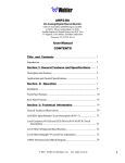
1
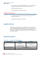
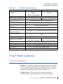
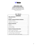
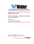
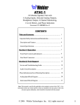
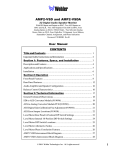
VM Series • VMMDA-1 • VMDA-4 1U Analog/Digital Audio Monitors User Guide Part Number 821026, Revision D © 2011 Wohler Technologies, Inc. All rights reserved. This publication is protected by federal copyright law. No part of this publication may be copied or distributed, stored in a retrieval system, or translated into any human or computer language in any form or by any means electronic, mechanical, manual, magnetic, or otherwise, or disclosed to third parties without the express written permission of Wohler Technologies. Reproduction Licensed users and authorized distributors of Wohler Technologies, Inc. products may copy this document for use with Wohler Technologies., Inc. products provided that the copyright notice above is included in all reproductions. Customer Support Wohler Technologies, Inc. 31055 Huntwood Avenue Hayward, CA 94544 www.wohler.com Phone: 510-870-0810 FAX: 510-870-0811 US Toll Free: 1-888-596-4537 (1-888-5-WOHLER) Web: www.wohler.com Sales: [email protected] Support: [email protected] Disclaimers Even though Wohler Technologies, Inc. has tested its equipment and software, and reviewed the documentation, Wohler Technologies, Inc. makes no warranty or representation, either express or implied, with respect to software, documentation, their quality, performance, merchantability, or fitness for a particular purpose. Wohler Technologies, Inc. reserves the right to change or improve our products at any time and without notice. In no event will Wohler Technologies, Inc. be liable for direct, indirect, special, incidental, or consequential damages resulting from any defect in the hardware, software, or its documentation, even if advised of the possibility of such damages. Some states do not allow the exclusion or limitation for incidental or consequential damages, so the above exclusion or limitation may not apply to you. Printing This document is intended to be printed on a duplex printer, such that the copy appears on both sides of each page. This ensures that all new chapters start on a right-facing page. This document looks best when printed on a color printer since some images may be indistinct when printed on a black and white printer. Other Technologies and Products Dolby, Dolby Digital, Dolby D, and Dolby E are registered trademark of Dolby Laboratories, Inc. Microsoft Windows, and Internet Explorer are registered trademarks of Microsoft Corporation. Last Update July 05, 2011 ii 821026: V M S e r i e s U s er G u i d e © 2 0 1 1 Wo h l e r Tec h n o l o g i e s , I n c. A l l r i g h t s r e s er ve d . VM Series User Guide Introduction Overview The single-rackspace VM Series monitors permit selectable monitoring of from one to four stereo analog or AES audio sources, with excellent full-range fidelity far exceeding that of an ordinary monitor. The VMDA-4 can monitor stereo analog or AES audio sources while the VMMDA-1 can monitor analog, AES, SD-SDI, or HD-SDI audio sources. Topics Topics Introduction Page 1 Safety Instructions 2 Installation Recommendations 3 FCC Compliance 4 Features 5 Applications 6 Specifications 6 Front Panel Controls 7 Rear Panel Connectors 10 Technical Functional Overview 13 8 2 1 0 2 6 : V M S e r i e s Us e r G u i d e © 2 0 1 1 Wo h l e r Tec h n o l o g i e s, I n c. A l l r i g h t s r e s er ved . 1 V M S e r ie s U s e r G u i d e S a f e t y I n s tr u c ti o n s Safety Instructions IMPORTANT: 1. Read, keep, and follow all of these instructions; heed all warnings. 2. Do not use this equipment near water or moisture. 3. Use only a dry cloth to clean the equipment. 4. Do not block any ventilation openings. Install only in accordance with the instructions in the section entitled, “Installation Recommendations” on page 3. 5. Do not install near any heat source such as a radiator, heat register, amplifier, or stove. 6. Do not attempt to plug the unit into a two-blade outlet (with only two prongs of equal width). By design, these monitors will only plug into a three-prong outlet for your safety. If the plug does not fit into your outlet, contact an electrician to replace the obsolete outlet. 7. Protect the power cord from being walked on or pinched, particularly at plug’s source on the equipment and at the socket. 8. Use only the attachments/accessories specified by the manufacturer. 9. Unplug the equipment during lightning storms or when unused for long periods of time. 10. Refer all servicing to qualified service personnel. Servicing will be required under all of the following conditions: 2 821026: • The equipment has been damaged in any way, such as when the power-supply cord or plug is damaged. • Liquid had been spilled or objects have fallen onto the equipment. • The equipment has been exposed to rain or moisture. • The equipment does not operate normally. • The equipment has been dropped. V M S e r i e s U s er G u i d e © 2 0 1 1 Wo h l e r Tec h n o l o g i e s , I n c. A l l r i g h t s r e s er ve d . VM Series User Guide I n s ta l la t i o n R e c o m me n d a t io n s Installation Recommendations Mounting The unit is designed to install into a standard 19" rack mounted at eye level for best visual observation of the monitor screens. Heat Dissipation The ambient temperature inside the mounting enclosure should not exceed 40° Celsius (104° Fahrenheit). Adjacent devices can be rack mounted (or stacked) in proximity to the unit if the above temperature is not exceeded. Allow a 1RU (1.75”/44.45mm) space above and below the unit for air circulation. Important: To reduce noise, the monitor have any fans. As a result, the heat generated by the class D power amplifiers, power supplies, and other components is vented by slots in the side of the unit. Therefore, as a safety precaution, we advise you to be sure to allow proper ventilation on both sides of the unit. Power The unit comes with a standard 24VDC/3.0A internal power supply and connects an A/C mains power source (65W, 100 to 240 VAC, 50/ 60Hz) to the IEC connector provided on the rear panel of the unit. Sympathetic Vibration Sympathetic vibration from other equipment (cables, etc.), in the rack may be serious enough to interfere with the unit’s sound quality out in the listening area. The use of thin card stock and/or felt or foam weather-stripping type materials between adjacent vibrating surfaces, or tying up loose cables, etc., may be required to stop vibrations external to the unit. 821026: VM Series User Guide © 2 0 1 1 Woh l er Te c h n o l o g i es , I n c . A ll r i g h t s r e se r ve d . 3 V M S e r ie s U s e r G u i d e FCC Compliance Mechanical Bracing The chassis is securely attached to the front panel at eight points along its surface, not just at the four corners of the chassis ears. This feature will reduce or eliminate rear bracing requirements in many mobile/ portable applications. The weight of internal components is distributed fairly evenly around the unit. Audio Connections Connection of the audio feeds is straightforward. Care should be exercised to avoid mismatched cable types and other similar causes of undesired refl ections in RF signal systems. Electrical Interference As with any audio equipment, maximum immunity from electrical interference requires the use of shielded cable; however, satisfactory results can sometimes be obtained without it. The internal circuitry common is connected to the chassis. FCC Compliance This equipment has been tested and found to comply with the limits for a Class A digital device, pursuant to part 15 of the FCC Rules. These limits are designed to provide reasonable protection against harmful interference when the equipment is operated in a commercial environment. This equipment generates, uses, and can radiate radio frequency energy and, if not installed and used in accordance with the instruction manual, may cause harmful interference to radio communications. Operation of this equipment in a residential area is likely to cause harmful interference in which case the user will be required to correct the interference at his own expense. 4 821026: V M S e r i e s U s er G u i d e © 2 0 1 1 Wo h l e r Tec h n o l o g i e s , I n c. A l l r i g h t s r e s er ve d . VM Series User Guide Features Features Common Features • Only one rack space high, but produces a powerful 96 dB SPL at two feet • Electronic power output limiting prevents speaker blowout • Thoroughly magnetically shielded • Headphone jack with speaker muting • Balanced analog inputs • AES input on balanced Phoenix connector and unbalanced BNC connector • Selectable termination on AES input • Balanced stereo analog output of selected source • Lightweight and shallow-depth chassis • Internal universal AC mains power supply • Two 10-segment LED bargraph audio level meters • Phase indication LEDs • Power indication LED • Volume and Balance controls (jumper-configurable as A volume/ B-volume, by specifying option SVC) VMMDA-1 Features • Monitors analog, AES, and SD-SDI or HD-SDI audio sources • Source selected using a front panel 3-position toggle switch (analog, AES, or SDI) 821026: VM Series User Guide © 2 0 1 1 Woh l er Te c h n o l o g i es , I n c . A ll r i g h t s r e se r ve d . 5 V M S e r ie s U s e r G u i d e Applications • One of eight channel pairs from SDI Groups 1 to 4 selectable with front panel rotary switch (when SDI is the selected source) • LED indicates SDI lock status • Two analog inputs on Phoenix connectors VMDA-4 Features • Selectable monitoring of one of four stereo analog or four AES channels in one unit • Analog channel pairs may be summed Applications The VM Series of audio monitors are ideally suited to provide high quality analog/digital audio monitoring in a very compact form. Ideal for use in VTR bays, mobile production vehicles, teleconferencing installations, multimedia systems, satellite links, cable TV facilities, and on-air radio studios. Specifications Table 1–1 VM Series Specifications Specification Inputs Analog input impedance AES Input Impedance 6 821026: VMMDA-1 VMDA-4 2 Analog: "mini" Phoenix Analog: "mini" Phoenix (balanced). (balanced). 1 AES: "mini" Phoenix/BNC 4 AES: "mini" Phoenix/BNC 1 SDI/HD-SDI: BNC >100k balanced AES 75 Unbalanced and 110 Balanced V M S e r i e s U s er G u i d e © 2 0 1 1 Wo h l e r Tec h n o l o g i e s , I n c. A l l r i g h t s r e s er ve d . VM Series User Guide Front Panel Controls Table 1–1 VM Series Specifications Specification Outputs Digital Input sampling rate: SDI Input Sampling Rate: Input level for full output (Volume full on): Hum and noise: Acoustic frequency response Maximum acoustic output Electrical distortion: (speaker outputs) Acoustic distortion Magnetic shielding Dimensions (HxWxD): Weight: Power Supply: Level Meter Type LED Color Metering Range VMMDA-1 VMDA-4 2 Analog (Selected): "mini" 2 Analog (Selected): "mini" Phoenix Phoenix 1 SDI (re-clocked): BNC 32 to 48 kHz, auto-sensing 48k Hz — 0 dBv balanced (analog); 20 dBfs (digital) Better than -70 dB below full output 60 Hz to 16 kHz (± 6dB) 96 dB SPL at 2 feet Less than 0.3% at any level below limiting threshold Typically < 2% at any level below limiting, 100 Hz-15 KHz Less than 0.2 Gauss any adjacent surface 1.75 x 19 x 10 in. 1.75 x 19 x 9.0 in. (44.5 x 483 x 246 mm.) (44.5 x 483 x 254 mm.) 6.8 lbs. (3.1kg) Universal AC input (100-240V) UL/ CSA approved LED bar graph Tri-Color (red, amber, green) 23 dB Front Panel Controls Common Controls • Speakers: The VMDA series internal speaker system is comprised of two mid-range tweeter speakers (left and right) and one impact woofer speaker (center). Speaker amp limiters prevent accidental damage to the speakers due to excessive input levels. • Volume Control: This controls the loudness of the audio reproduced by the internal speakers or connected headphone. 821026: VM Series User Guide © 2 0 1 1 Woh l er Te c h n o l o g i es , I n c . A ll r i g h t s r e se r ve d . 7 V M S e r ie s U s e r G u i d e Front Panel Controls • Audio Level Bar Graph Meter Displays: Audio levels for the selected source channels are displayed via two 10-segment LED bar graph meters (one on the left side of the front panel; one on the right side). Dynamic range for these meters is 23dB. Contact the factory for additional meter information concerning meter scales and ballistics. • Headphone Jack: For critical listening or for listening in high noise environments, use the headphone feature rather than the internal speakers. Select the headphone audio sources as you would for the internal speakers. When you plug in headphones, the internal or external speakers will mute. This jack accepts the standard 1/4” phone type stereo plug. • Power Indicator LED: The Power Indication LED signals the operating condition of the power supply. The LED glows green to indicate the unit is connected to mains power and an operation voltage is present. • Balance Control: This pans the volume balance between the left and right speakers. • Phase Indication LEDs: The phase indication LEDs offer immediate verification of phase (polarity) relationships in stereo or mono sources. There are three LEDs; the two smaller LEDs on top and bottom show instantaneous (fast) phase relationships in the signal, while the center (and larger) LED will indicate the average phase condition. The small top, or in-phase, LED (FAST-IN) glows (or blinks) green when signals are in phase. The small bottom , or out-of-phase, LED (FAST-OUT) glows (or blinks) amber for out of phase signals. The large center LED (AVG) indicates the average phase condition by glowing green for in-phase conditions, or red for out-of-phase conditions. In general, it is sufficient to regard the center LED (average phase condition) as adequate for proper phase monitoring. While it is normal for stereo signals to contain some intermittant instantaneous out-of-phase and in-phase conditions (small LEDs), a steady red glow of the larger center LED almost always indicates an out-ofphase alarm condition. 8 821026: V M S e r i e s U s er G u i d e © 2 0 1 1 Wo h l e r Tec h n o l o g i e s , I n c. A l l r i g h t s r e s er ve d . VM Series User Guide Front Panel Controls VMDA-4-Specific Controls Figure 1–1 VMDA-4 Front Panel Level Meters Volume Balance Power Channel Select Headphones Phase Input Select and Speaker Mute Speakers • Channel Select Buttons (VMDA-4 Only): These four buttons select which channel(s) will be monitored through the speakers and are labeled 1 through 4. When monitoring analog signals it is possible to monitor from one to four stereo pairs. When monitoring two, three, or four analog stereo pairs, the channel pairs are summed together and are reproduced simultaneously from the left and right speakers. However, when monitoring digital signals, only one stereo pair at a time may be monitored. An LED in each button lights up to indicate which channel(s) are selected for monitoring. • Input Select / Speaker Mute Button: This button serves a dual function; it selects between the two input signal types (digital AES/ EBU or analog) and also toggles the speaker mute feature on and off. • Source Select: The button exhibits a steady green glow to indicate that the unit is monitoring the digital inputs and the button is unlit when indicating that the unit is monitoring the analog inputs. To toggle between the digital and analog source types, the button is depressed for one second. • Mute: To mute the speakers at any time, the button is briefly tapped once, the button blinks to indicate it is in mute mode. A second single tap unmutes the speakers. 821026: VM Series User Guide © 2 0 1 1 Woh l er Te c h n o l o g i es , I n c . A ll r i g h t s r e se r ve d . 9 V M S e r ie s U s e r G u i d e R e a r P a n e l C o n n e ct o r s VMMDA-1-Specific Controls Figure 1–2 Volume VMMDA-1 Front Panel Level Meters SDI Lock Power Balance Group Channel Select Headphones Phase Source Select Speakers • SDI Lock Status LED: This LED indicates the lock status of the SDI source signal. It glows green to indicate a locked SDI signal and is unlit to indicate an unlocked SDI signal (or that no SDI source is connected). This LED indicates SDI lock status continuously regardless of any other selection settings. • SDI Group Channel Select Switch: This 8-position rotary switch selects one of the eight channel pairs (from SDI Groups 1-4) that will be monitored from the connected SDI source. Note that in order to audibly monitor the selected SDI channel pair, the Source Select Switch must be set to SDI. • Source Select Switch: This 3-position toggle switch selects the source to be monitored through the unit (SDI, AES, or analog). Rear Panel Connectors Common Connectors • Power Connector: Attach a standard IEC-320 power cord between this connector and mains power (100 - 240VAC nominal, 50/60 Hz). The front panel power LED will glow green to indicate an operating voltage is present. 10 821026: V M S e r i e s U s er G u i d e © 2 0 1 1 Wo h l e r Tec h n o l o g i e s , I n c. A l l r i g h t s r e s er ve d . VM Series User Guide Rear Panel Connectors • Analog Output Connector (Left and Right): This "mini" Phoenix style (Mini-Combicon) dual vertical, 6-position terminal block connector outputs an analog signal of the source currently selected for monitoring. When the selected source is digital (AES, SDI, or HD-SDI), the unit will automatically de-embed the audio to analog for output from this connector. The top three positions are the left output; the bottom three positions are the right output. Pinout information is silk-screened just below the connector. VMDA-4-Specific Connectors Figure 1–3 VMDA-4 Rear Panel AES In 1, 2, 3, and 4 Balanced Wohler ANALOG OUTPUT Technologies Tel +1-510-870-0810 Fax +1-510-870-0811 www.Wohler.com ANALOG INPUT AES 2 AES 4 TERM. 1 LEFT AES 1 VMDA-4 253890-01 SERIAL NO. TERM. 4 AES 3 AES 2 1 2 3 4 LEFT AES 4 RIGHT AES Term Analog Out Power AES Term HI LO AES 3 HI LO AES 1 HI LO HI LO YEAR HI LO RIGHT HI LO MONTH MADE IN U.S.A. TERM. 3 TERM. 2 HI LO 100-240 VAC 50/60 Hz 1.0 A Analog In AES In 1, 2, 3, and 4 Unbalanced • AES In: These connectors receive standard AES/EBU digital signals. There are a total of four inputs. Inputs are labeled AES 1, AES 2, AES 3, and AES 4. The BNC connectors are configured as 75 unbalanced inputs. The AES Phoenix connectors are for 110 balanced inputs. VMMDA-1-Specific Connectors Figure 1–4 VMMDA-1 Rear Panel AES In RS-232 ANALOG OUTPUT 100-240 VAC 50/60 Hz 1.0 A SDI IN SDI OUT ANALOG INPUT TERM. LEFT AES 1 Power www.Wohler.com RIGHT HI LO YEAR LEFT Tel +1-510-870-0810 Fax +1-510-870-0811 MONTH HI LO SERIAL NO. Wohler Technologies AES 1 AES Termination SDI In and Loop Out Analog Out 253234-01 RIGHT HI LO RS232 Analog In • SDI In: This BNC input connector (SDI In) is configured for unbalanced, 75 Ω impedance connections. In the VMMDA-1 model, 821026: VM Series User Guide © 2 0 1 1 Woh l er Te c h n o l o g i es , I n c . A ll r i g h t s r e se r ve d . 11 V M S e r ie s U s e r G u i d e R e a r P a n e l C o n n e ct o r s this input accepts either standard SDI or HD-SDI (high-definition SDI) formatted digital signals. To monitor the digital source signals entering this input connector, set the Source Select switch to SDI. Note: The SDI Lock Status LED will continue to indicate SDI lock status for this input even when the SDI source is not selected for monitoring. • SDI Out: This BNC connector (SDI Out) outputs a reclocked (regenerated) copy of the signal entering the SDI In. • RS-232: This connector is not currently used and is reserved for future use. • AES In: The female BNC connector receives AES digital signals and is configured for unbalanced 75 Ω impedance connections. To monitor the digital source signals entering this input connector, set the Source Select switch to AES. The AES Phoenix connector is for 110 balanced inputs. Note: There is only one AES input channel; do not connect two AES signal sources simultaneously to both the balanced and unbalanced AES input connectors. Only one AES input connector (balanced or unbalanced) should be used at a time. • AES Termination DIP Switch: This 2-position DIP switch module is used to set the termination characteristics for the AES input channel (both balanced and unbalanced). In the event that the AES input channel is fed to downstream equipment, DIP switch section 1 (left-side switch) should be placed in the up (unterminated) position. If there are no downstream connections, then DIP switch section 1 should be placed in the down(terminated) position. Note that Section 2 of the DIP module is not used. • Analog In: This "mini" Phoenix style (Mini-Combicon) dual vertical, 6-position terminal block connector accepts standard analog signals and is configured for balanced 100k Ω impedance connections. The top three positions are the left input; the bottom three positions are the right input. Pinout information is silkscreened just below the connector. To monitor the analog source signals entering this input connector, set the Source Select switch to Analog. 12 821026: V M S e r i e s U s er G u i d e © 2 0 1 1 Wo h l e r Tec h n o l o g i e s , I n c. A l l r i g h t s r e s er ve d . VM Series User Guide T e c h n i c al F u n c ti o n al O v e r v ie w Technical Functional Overview Figure 1–5 below and Figure 1–6 on page 14 illustrate the overall functionality of the VM Series monitors. Figure 1–5 1 Analog 2 Stereo 3 Inputs (1-4) 4 Analog to Digital Converter Analog/ Digital/ Mute Select A M Channel Select D (AES = 1 of 4 Stereo Pairs Only) (Analog = Sum 1-4 Stereo Pairs to L/R) A M 1 D AES 2 Inputs 3 (Unbal.) AES Receiver 4 2 AES Inputs (Bal.) VMDA-4 Block Diagram 1 1 2 3 4 10-Segment Level Meters Headphone Volume Balance Left Speaker Left D to A Converter A M Stereo Analog Amplifier Woofer D A M D Right Analog Stereo Output of Selected Source Phase Indication Right Speaker 4 3 8 2 1 0 2 6 : V M S er ie s U s e r G u i d e © 2 0 1 1 Woh l e r Te c h n o l o g i es , I n c . A l l r i g h t s r e se r ve d . 13 VM Series User Guide Technical Functional Overview Figure 1–6 HD/SD-SDI Output AES 14 Input (Bal.) Input (Unbal.) 821026: ReClock G1-1,2 G1-3,4 G2-1,2 G2-3,4 G3-1,2 G3-3,4 G4-1,2 G4-3,4 Group/Subgroup Select SDI to AES De-Embed SDI Decoder AES Receiver V M S er ie s U s e r G u i d e © 2 0 1 1 Woh le r Te ch n o l o g i e s , I n c . A l l r ig ht s r es e r ve d . ANA SDI AES Analog/ Digital/ Mute Select Headphone 10-Segment Level Meters Volume Balance Left Speaker D to A Converter Stereo Analog Amplifier Woofer Phase Indication Right Speaker Analog to Digital Converter Analog Input (1-2) Input VMMDA-1 Block Diagram Analog Stereo Output of Selected Source