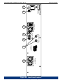
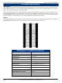
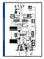
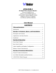
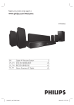
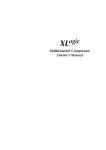
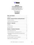
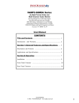
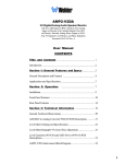
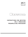
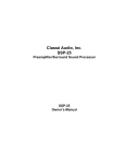
1
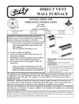
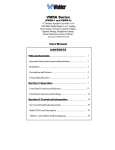
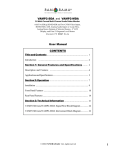
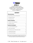
ATSC/DVB-3/SDI
2U Digital Audio Speaker Monitor
with SDI, AC-3, and AES Inputs on XLR and BNC,
Analog Stereo Output of Selected Source on XLR,
Six 53-Segment Level Meters and Phase Indication
Document P/N 821557 Rev. A
User Manual
CONTENTS
Title and Contents ............................................................. 1
Introduction ...................................................................................... 2
Section 1: General Features and Specs .................. 3
Description and Features .................................................................. 4
Applications and Specifications..................................................... 5
Section 2: Operation ........................................................ 7
Installation ....................................................................................... 9
Front Panel Features ........................................................................ 10
Rear Panel Features
.................................................................... 14
Section 3: Technical Information ................................ 17
General Technical Observations ................................................... 18
SDI to AES/EBU PCB (919096) Description ................................. 19
Level Meter Settings and Specifications ........................................ 20
ATSC/DVB-3/SDI Interconnect Block Diagram ............................ 21
1
Important Safety Instructions
1)
Read these instructions.
2)
Keep these instructions.
3)
Heed all warnings.
4)
Follow all instructions.
5)
Do not use this apparatus near water.
6)
Clean only with dry cloth.
7)
Do not block any ventilation openings. Install in accordance with the manufacturer's instructions.
8)
Do not install near any heat source such as radiators, heat registers, stoves, or other apparatus (including
amplifiers) that produce heat.
9)
Do not defeat the safety purpose of the polarized or grounding-type plug. A polarized plug has two blades
with one wider than the other. A grounding type plug has two blades and a third grounding prong. The
wide blade or the third prong are provided for your safety. If the provided plug does not fit into your outlet,
consult an electrician for replacement of the obsolete outlet.
10) Protect the power cord from being walked on or pinched, particularly at plugs convenience receptacles
and the point where they exit from the apparatus.
11) Only use attachments/accessories specified by the manufacturer.
12) Use only with the cart stand, tripod, bracket, or table specified by the manufacturer, or sold with the
apparatus. When a cart is used, use caution when moving the cart/apparatus combination to avoid injury
from tip-over.
13) Unplug this apparatus during lightning storms or when unused for long periods of time.
14) Refer all servicing to qualified service personnel. Servicing is required when the apparatus has been
damaged in any way, such as when power-supply cord or plug is damaged, liquid has been spilled or
objects have fallen into the apparatus, the apparatus has been exposed to rain or moisture, does not
operate normally, or has been dropped.
15) Do not expose this apparatus to rain or moisture.
16) The apparatus shall be connected to a mains socket outlet with a protective earthing connection.
CAUTION!
In products featuring an audio amplifier and speakers, the surface at the side of the
unit, where the audio amplifier heat sink is internally attached, may get very hot after
extended operation. When operating the unit excercise caution when touching this
surface and ensure that external materials which may be adversely affected by heat
are not in contact with it. There is a Hot Surface label (see diagram) attached to the
aforementioned surface of the product.
Introduction
Congratulations on your selection of a Wohler Technologies product. We are confident it represents the best performance and value
available, and we guarantee your satisfaction with it.
If you have questions or comments you may contact us at:
Wohler Technologies, Inc.
31055 Huntwood Avenue
Hayward, CA 94544
Phone: (510) 870-0810
Fax: (510) 870-0811
US Toll-Free: 1-888-596-4537
www.wohler.com
2
[email protected]
© 2007 Wohler Technologies, Inc. ALL rights reserved
ATSC/DVB-3/SDI User Manual P/N 821557 Rev-A
Sect. 1: General Features and Specifications
Section 1
General Features
and Specifications
Description
Features
Applications
Specifications
Other Options
© 2003 Wohler Technologies Inc. ALL rights reserved
3
ATSC/DVB-3/SDI User Manual P/N 821557 Rev-A
Section 1: General Features and Specifications
ATSC/DVB-3/SDI
2U Stereo Digiotal Audio Speaker Monitor
AVG O
OUT
IN
POWER
1
WOHLER
TECHNOLOGIES
2
3
0
2
4
7
10
13
16
18
20
22
25
28
31
34
38
42
46
51
56
66
4
SDI GROUP
SELECTOR DISABLED
3
4
2
1
LEFT SPEAKER
SELECT
5
6
L FRONT
1
INPUT
STATUS
0
2
4
7
10
13
16
18
20
22
25
28
31
34
38
42
46
51
56
66
R FRONT
2
AC-3
0
2
4
7
10
13
16
18
20
22
25
28
31
34
38
42
46
51
56
66
PCM
1
SDI
2
PRO-16
SELECT
INPUT
SOURCE
1 -AES
ALL
2 -SDI
SELECTED
CENTER
3
LF EFX
4
SOURCE
0
2
4
7
10
13
16
18
20
22
25
28
31
34
38
42
46
51
56
66
L SURR
5
1
ATSC/DVB-3/SDI
DIGITAL AUDIO
MONITOR PANEL
2
SUBGROUP
SELECTOR DISABLED
3
2
R SURR
6
SOURCE
1
4
5
6
RIGHT SPEAKER
SELECT
ATSC/DVB-3/SDI Front Panel
Description
The ATSC/DVB-3/SDI is a powered stereo monitor designed specifically for flexible, comprehensive monitoring of the six audio
channels associated with ATSC/DVB programming. The unit is 2RU in size, for excellent fidelity without using excessive rackspace
in the critical "operating zone" of rack bays and consoles.
The ATSC/DVB-3/SDI monitors SDI (Serial Digital Interface), PCM (Pulse Code Modulation), AES/EBU, and AC-3 (Dolby Digital®) signals providing capabilities to handle monitoring requirements throughout the facility.
The speakers and amplifiers are arranged in the popular Wohler “biamp summed bass stereo” configuration: bass frequencies from
ALL selected channels are summed into a 20 watt amplifier, which drives the woofer. The two side channel amplifiers and speakers
reproduce, in stereo, only the mid- and high-frequencies. Note that the center speaker (the woofer) is NOT a dedicated Center nor
LFE speaker. There is also a headphone output, which mutes the speakers while in use.
Six high-resolution wide-range LED bargraph level meters are provided for all six channels for very accurate metering. Fifty-three bicolor segments spanning a range of 65 dB simultaneously display signal levels according to both the PPM and VU standards. An
adjustable-duration hold of the Peak PPM value may also be displayed.
Both Left/Right and Front/Surround "Phase"/Polarity LED indications are provided to alert of possible cancellation from mixdown in
any likely playback situation.
To isolate possible faults, two rotary switches on the front panel let the operator route any one or pair of inputs independantly to left and
right speaker channels for acoustic monitoring. A toggle switch is provided for mixing all six channels down to two for listening to all
channels at once.
Features
• 2U high: highest fidelity in minimum rackspace
• Pro-16 signal select switch and indication LED
• Monitors SDI, AC-3 (Dolby Digital), and PCM or AES/EBU
audio signals
• Left/Right Front “phase" indicators
• Simultaneous visual monitoring of all 6 channels
• 53-segment tri-color, wide-range, high-resolution LED
bargraph level meters
• Select any channel or pair of channels for isolated listening, or
a stereo mixdown of all 6 channels
• Selected channel analog outputs on XLR connectors
• Headphone output
• SDI, AC-3, and PCM or AES/EBU Status Indication LEDs
4
© 2003 Wohler Technologies Inc. ALL rights reserved
ATSC/DVB-3/SDI User Manual P/N 821557 Rev-A
Section 1: General Features and Specifications
Applications
The ATSC/DVB-3/SDI is ideally suited for use in VTR bays, mobile production vehicles, teleconferencing installations, multimedia
systems, satellite links and cable TV facilities, and on-air radio studios. Designed and manufactured in the U.S., the ATSC/DVB-3/SDI
is backed by a strong warranty and a satisfaction guaranteed return policy.
General Specifications
AC-3 Input Specifications
Input Meter Dynamics:
Simultaneous VU (bar) and PPM (dot)
Peak Acoustic Output
(@ 2 ft.):
104 dB SPL
Response, Sixth Octave:
Power Output,
Ω):
RMS Each Side (4Ω
Ω):
RMS Bass (4Ω
70 Hz - 16 kHz ± 5 dB)
(-10 dB @ 40 Hz, 20 kHZ)
Input Connectors:
BNC
Minimum Input level:
250 mV
Playback Mode:
“Line”
Input Impedances/
Connectors:
Less than 0.2% at any level below
limit threshold
Distortion, Acoustic:
75Ω (ohm), unbalanced
PCM and AES/EBU Input Specifications
20 W transient / 11 W continuous
36 W transient / 20 W continuous
Distortion, Electrical:
Input Impedance:
6% or less at worst case frequencies
above 120 Hz, including cabinet
resonance; typically less than 1.5%
Conversion Data
Width:
20 bit
Dynamic range:
95 dB
Frequency Response:
10 Hz - 20 kHz +/- 0.5 dB
< 0.005%
Hum and Noise:
Better than -70 dB below full output
Magnetic Shielding:
Less than 1 Gauss any adjacent surface
Analog Output
Distortion:
Input Connectors:
Balanced: XLR
Analog Outputs:
Power Consumption
(Average Maximum):
60 Segments
W
Medium-size
Medium-size Segments
(for Middle -distance Viewing
(forInput:
Middle -distance
Viewing
AC Mains
100-220VAC,
50-60 Hz
"ALL" Channel Summing
Assignments*:
balanced, line-level
(-20 dbfs=+4 dBu); minimum
load impedance:10k Ω (ohm)
SDI Input Specifications
Left Side =LFront+LSurr+1/2Center+1/2LFE
Right Side =RFront+RSurr+1/2Center+1/2LFE
* On special order, custom combinations of selected channels are available;
either in lieu of, or in addition to, the regular selections.
Input Impedance:
75Ω (ohm), unbalanced
Input Connector:
BNC
SDI Input Level:
400 - 1000 mV
Input Formats:
Componant, 525 or 625
lines with 48 kHz audio
Audio Sampling Rate:
48 kHz
Audio Response Curve
+10
Note: See pages 18-20 for additional technical specifications.
0
d
B
BNC:75 Ω (ohm), unbalanced
XLR:110 Ω (ohm) balanced
.
Physical Specifications
-10
-20
-30
20
50
100
200
500
1k
2k
5k
Hz
10k
Weight:
18 lbs. (8.2 kg)
Dimensions (HxWxD):
3.5 x 19 x 12 inches
(89 x 483 x 298 mm)
20k
Typical 1/6 Octave Audio Response Curve
Units are designed to meet, at time of manufacture, all currently applicable product safety and EMC requirements, such as those of CE. 0 dbV ref. 0.775V
RMS. Features and specifications subject to improvement without notice.
© 2003 Wohler Technologies Inc. ALL rights reserved
5
ATSC/DVB-3/SDI User Manual P/N 821557 Rev-A
(This page intentionally left blank)
6
© 2003 Wohler Technologies Inc. ALL rights reserved
ATSC/DVB-3/SDI User Manual P/N 821557 Rev-A
Section 2
Operation
Installation
Front Panel Features
Rear Panel Features
© 2003 Wohler Technologies Inc. ALL rights reserved
7
ATSC/DVB-3/SDI User Manual P/N 821557 Rev-A
(This page intentionally left blank)
8
© 2003 Wohler Technologies Inc. ALL rights reserved
Section 2: Operation
ATSC/DVB-3/SDI User Manual P/N 821557 Rev-A
Section 2: Operation
Installation
Mounting
NOTE: Be sure to set the Input Termination (accessed through the rear panel), BEFORE installing the unit into an enclosed rack
or console. See Item E, page 14 for setting information.
The unit should be mounted where convenient for operating persons, ideally at approximately ear level for best high frequency
response and eye level for best visual observation of the level meters. Its superior magnetic shielding eliminates concerns about
locating it adjacent to most types of CRT monitors, including even high-resolution color monitors.
Heat Dissipation
Heat dissipated by the speaker amps is conducted directly to the left side of the chassis; no special considerations for cooling are
necessary as long as the ambient temperature inside the rack area does not exceed approximately 40°C (104°F).
Sympathetic Vibration
Sympathetic vibration from other equipment (cables, etc.,) in the rack may be serious enough to interfere with the unit’s sound
quality out in the listening area. The use of thin card stock and/or felt or foam weather-stripping type materials between adjacent
vibrating surfaces, or tying up loose cables, etc., may be required to stop vibrations external to the unit.
Mechanical Bracing
Even though the unit is fairly heavy, the chassis is securely attached to the front panel at eight points along its surface, not just at
the four corners of the chassis ears. This feature will reduce or eliminate rear bracing requirements in many mobile/portable
applications. The weight of internal components is distributed fairly evenly around the unit.
Audio Connections
Connection of the audio feeds is straightforward. Please refer to the system interconnect block diagram on page 21 for clarification of the general signal paths into and out of the ATSC/DVB-3/SDI unit.
Inputs are via either BNC or XLR connectors. BNC inputs are 75 Ω unbalanced; XLRs are 110 Ω balanced.
Electrical Interference
Care should be exercised to avoid mismatched cable types and other similar causes of undesired reflections in RF signal systems.
If severe enough, such reflections can result in undesirable electrical interference in the audio signals.
As with any audio equipment, maximum immunity from electrical interference requires the use of shielded cable; however,
satisfactory results can sometimes be obtained without it. The internal circuitry common is connected to the chassis.
AC Power
The unit's AC mains connection is via a standard IEC inlet, with safety ground connected directly to the unit's chassis. The
universal AC input (100-240VAC, 50/60Hz) switching power supply is a self-resetting sealed type, with automatic over-voltage
and over-current shutdown. There is no user-replaceable fuse in either the primary or secondary circuit.
© 2003 Wohler Technologies Inc. ALL rights reserved
9
ATSC/DVB-3/SDI User Manual P/N 821557 Rev-A
Section 2: Operation
Front Panel Features
Please refer to Figure-2a on the following page to familiarize yourself with the front panel features of the ATSC/DVB-3/SDI unit.
The following sections describe these features and are referenced, by number, to Figure-2a.
1
Speakers (Left/Middle/Right)
The ATSC/DVB-SDI internal speaker system is comprised of two mid-range tweeter speakers (left and right) and one
woofer speaker (middle). The two side channel speakers reproduce, in stereo, only the mid and high frequencies. Please note
that the woofer speaker (middle) is not a dedicated Center nor LFE speaker.
2
Speaker Select Switches (Left and Right)
Use the left switch to select any one of six selected channels for monitoring from the left speaker. Use the right switch to
select any one of six selected channels for monitoring from the right speaker.
Note: These two switches are only functional when the All/Selected Switch (Item 7) is in the SELECTED position. These
two switches are NOT functional when the All/Selected Switch is in the ALL position.
3
Speaker Select Disabled Indication LEDs (Left and Right)
When the All/Selected Switch (Item 7) is in the ALL position (thus disabling the Speaker Monitor Select Switches) both
of these LEDs will glow RED.
4
Audio Level Meter LED Bargraph Displays (1-6)
Audio levels for source channels 1 through 6 are displayed via these six high-resolution 53-segment LED bargraph display
level meters (three on the left side of the front panel; three on the right side). Dynamic range for these meters is 65 dB and
they are able to display signal levels using both PPM and VU standards. An adjustable-duration hold of peak PPM value may
also be displayed. Each meter is labeled according to the standard Surround Sound nomenclature (left front, right front, center,
low frequency effects, left surround, and right surround). See page 20 for more information about these level meters.
5
Bargraph Brightness Trim Pot (Left and Right)
These two trim pots are recessed into the front panel and can be accessed using a small screwdriver. Turning either trim pot
clockwise will increase the relative brightness of the associated bargraph display LED segments. The left trimpot affects the left
three bargraph displays (1-3); the right trim pot affects the right three bargraph displays (4-6).
6
Input Source Select Switch
This 2-position toggle switch allows the operator to choose between two possible input sources (1-AES or 2-SDI) for
monitoring through the unit. Choosing 1-AES selects the AC-3 or PCM/AES signals entering the Source 1 connectors on
the rear panel (See Items C and D, page 14). Choosing 2-SDI selects an AC-3 or PCM/AES source that is de-embedded
from the SDI signal entering the Source 2 connector on the rear panel (see Item F, page 14).
7
All/Selected Switch
When this 2-position toggle switch in in the ALL position, a stereo mixdown of the five full channels is applied to the speaker
amps (the LFE channel is excluded). In this posiotion both the left and right Speaker Select Switches (Item 2) are disabled
and the Speaker Select Disabled Indication LEDs (Item 3) will glow RED.
When this switch is in the SELECTED position, channel selection defaults to the settings as selected by the left and right
Speaker Select Switches (Item 2) and the left and right Speaker Select Disabled Indication LEDs (Item 3) will be unlit.
8
SDI Group Select Switch (1, 2, 3, or 4)
This 4-position rotary switch allows the operator to choose SDI GROUP 1, 2, 3, or 4 for monitoring. The Subgroup (1 or 2)
of each SDI GROUP is selected using the SDI Subgroup Select Switch (Item 17, page 12).
Note that the Input Source Select Switch (Item 6) must be set to 2-SDI in order for the selected SDI signals to be actively
monitored.
9
Volume Control Pot
This controls the loudness of the audio reproduced by the internal speakers or connected headphone. Clock-wise rotation of
this control increases the loudness of the monitored audio.
(Continued)
10
© 2003 Wohler Technologies Inc. ALL rights reserved
Section 2: Operation
ATSC/DVB-3/SDI User Manual P/N 821557 Rev-A
WOHLER
TECHNOLOGIES
1
2
3
4
SDI GROUP
3
4
5
6
POWER
SELECTOR DISABLED
2
1
LEFT SPEAKER
SELECT
IN
OUT
SOURCE
R FRONT
2
0
2
4
7
10
13
16
18
20
22
25
28
31
34
38
42
46
51
56
66
AVG O
L FRONT
1
0
2
4
7
10
13
16
18
20
22
25
28
31
34
38
42
46
51
56
66
CENTER
3
SDI
1 -AES
INPUT
SOURCE
2 -SDI
INPUT
STATUS
AC-3
\\Snapserver\Users\Emilio\Dolby Digital LOGO.tif
PCM
1
2
PRO-16
SELECT
ALL
SELECTED
LF EFX
4
0
2
4
7
10
13
16
18
20
22
25
28
31
34
38
42
46
51
56
66
L SURR
5
SOURCE
0
2
4
7
10
13
16
18
20
22
25
28
31
34
38
42
46
51
56
66
R SURR
6
1
2
SUBGROUP
3
4
5
6
SELECTOR DISABLED
2
1
RIGHT SPEAKER
SELECT
DIGITAL AUDIO
MONITOR PANEL
ATSC/DVB-3/SDI
11
© 2003 Wohler Technologies Inc. ALL rights reserved
Figure-2a: Front Panel Features
ATSC/DVB-3/SDI User Manual P/N 821557 Rev-A
Section 2: Operation
Front Panel Features
(Continued)
10
Power Indication LED
This LED signals the operating condition of the power supply. The LED glows GREEN to indicate the unit is connected to
mains power and an operation voltage is present.
11 Phase Indication LEDs
These three LEDs offer instant verification of phase (polarity) conditions in the pair of channels selected for monitoring in the
left and right channel speakers. There are three LEDs; two smaller LEDs (labeled IN and OUT) on either side of a larger LED
(labeled AVG). The small IN and OUT LEDs show instantaneous phase relationships in the signal, while the larger AVG LED
indicates the average phase condition. The small IN LED on the left glows (or blinks) GREEN when signals are in-phase.
The small OUT LED on the right glows (or blinks) AMBER for out-of-phase signals. The large AVG LED indicates the
average phase condition by glowing GREEN for in-phase conditions, or RED for out-of-phase conditions. In general, it is
sufficient to regard the AVG LED (average phase condition) as adequate for proper phase monitoring. While it is normal for
stereo signals to contain some intermittant instanateous out-of-phase and in-phase conditions (small LEDs), a steady RED glow
of the larger LED almost always indicates an out-of-phase alarm condition.
12 SDI Signal Status Indication LED
This LED will indicate the status of any SDI signal entering Source 2 regardless of any monitor selection settings. This LED
shows the following conditions:
• OFF: No valid SDI signal present.
• GREEN: Valid SDI signal is present.
• RED: SDI signal not properly received.
13 Headphone Jack
Select the headphone audio sources as you would for the internal speakers. When you plug in headphones, the speakers will
mute. This jack accepts a standard 1/4” phone type stereo plug.
14 Input Status Indication LEDs (AC-3 and PCM)
These two green LEDs indicate which kind of signal is being received at the Source 1 inputs. When an AC-3 signal is being
monitored from Source 1 inputs, the left AC-3 LED will glow GREEN. When a PCM or standard AES/EBU signal is being
monitored from the Source 1 inputs, the right PCM LED will glow GREEN.
15 Pro-16 Selection Switch anf Indication LED
In the event that you are processing two different Dolby Digital Pro-16 data streams it is possible to select between the two
with this toggle switch. The LED will glow AMBER if such signals are present. In the absence of such data streams, the LED
will not be lit and the switch will be nonfunctional.
16 Balance Control Pot
This control pans the volume balance between the left and right speakers.
17 SDI Subgroup Select Switch (1 or 2)
This 2-position toggle switch allows the operator to choose whether the unit will monitor Subgroup 1 or Subgroup 2 of the
chosen SDI Group (1, 2, 3, or 4) as selected by the SDI Group Select Switch (Item 8, page 10). Subgroup selection
chooses the channels to be monitored from the selected SDI Group as follows:
Subgroup 1 = Channels 1 and 2
Subgroup 2 = Channels 3 and 4
Note that the Input Source Select Switch (Item 6) must be set to 2-SDI in order for the selected SDI signals to be actively
monitored.
12
© 2003 Wohler Technologies Inc. ALL rights reserved
Section 2: Operation
ATSC/DVB-3/SDI User Manual P/N 821557 Rev-A
WOHLER
TECHNOLOGIES
1
2
3
4
SDI GROUP
3
4
5
6
POWER
SELECTOR DISABLED
2
1
LEFT SPEAKER
SELECT
IN
OUT
SOURCE
R FRONT
2
0
2
4
7
10
13
16
18
20
22
25
28
31
34
38
42
46
51
56
66
AVG O
L FRONT
1
0
2
4
7
10
13
16
18
20
22
25
28
31
34
38
42
46
51
56
66
CENTER
3
SDI
INPUT
SOURCE
1 -AES
2 -SDI
INPUT
STATUS
AC-3
\\Snapserver\Users\Emilio\Dolby Digital LOGO.tif
PCM
1
2
PRO-16
SELECT
ALL
SELECTED
LF EFX
4
0
2
4
7
10
13
16
18
20
22
25
28
31
34
38
42
46
51
56
66
L SURR
5
SOURCE
0
2
4
7
10
13
16
18
20
22
25
28
31
34
38
42
46
51
56
66
R SURR
6
1
2
SUBGROUP
3
4
5
6
SELECTOR DISABLED
2
1
RIGHT SPEAKER
SELECT
DIGITAL AUDIO
MONITOR PANEL
ATSC/DVB-3/SDI
13
© 2003 Wohler Technologies Inc. ALL rights reserved
Figure-2a: Front Panel Features
ATSC/DVB-3/SDI User Manual P/N 821557 Rev-A
Section 2: Operation
Rear Panel Features
Please refer to Figure-2b on the following page to familiarize yourself with the rear panel features of the ATSC/DVB-3/SDI units.
The following sections describe these features and are referenced, by letter, to Figure-2b.
A
Power Connector
Attach the supplied IEC-320 power cord between this connector and mains power (100 - 240VAC nominal, 50/60 Hz). The
front panel Power Indication LED (Item 10, page 12) will glow GREEN to indicate operating voltages are present.
B
Option DIP Switch Module
This DIP switch is reserved for possible options still to be determined. You may disregard its settings.
C
Source 1 Input and Loop-Through Connectors (XLR)
The SOURCE 1 XLR input is meant to receive either AC-3 (Dolby Digital®) or standard PCM or AES signals. Both XLR
connectors are configured for a balanced connection (110 Ω impedance). The IN XLR connector is a 3-pin female. The
LOOP XLR connector is a 3-pin male. For pinout information see diagram below.
Pin-2
High (+)
D
Pin-1
Gnd
(Shield)
Pin-1
Gnd
(Shield)
Pin-2
High (+)
Pin-3
Low (-)
Pin-3
Low (-)
XLR, 3-Pin Female
INPUT Pinout
XLR, 3-Pin Male
OUTPUT Pinout
Source 1 Input and Loop-Through Connectors (BNC)
The Source 1 BNC input is meant to receive either AC-3 (Dolby Digital®) or standard PCM and AES/EBU signals. Both the
IN and LOOP BNC inputs are configured for an unbalanced connection (75 Ω impedance).
E
Termination DIP Switch Module
In the event that signals entering the Source 1 inputs (Item C and D) are connected to downstream equipment, then DIP switch
section 1 of this module should be set to UNTERMINATED (UP). If there is no connection to downstream euipment, then
section 1 should be set to TERMINATED (DOWN). Note: Section 2 of this DIP switch is not functional in the ATSC/DVB3/SDI model.
F
Source 2 Input and Output Connectors (BNC)
The BNC IN connector is meant to receive standard SDI signals. The BNC OUT connector outputs a reclocked (regenerated)
copy of the signal entering the input. Both connectors are configured for unbalanced connections (75 Ω impedance).
G
Selected Output (Analog) Connectors (Chan.A/Left and Chan.B/Right)
These two 3-pin male XLR connectors are Analog outputs of the input signals as selected for active monitoring through the left
and right speakers (or headphones). The left CH.A(L) connector outputs the left speaker channel (channel A) and the right
CH.B(R) connector outputs the right speaker channel (channel B). Both connectors are configured for low impedance
connections and the output signals are not affected by the Volume and Balance controls or Headphone Mute feature. For
XLR connector pinout information, see the diagram under Item C, above.
14
© 2003 Wohler Technologies Inc. ALL rights reserved
Section 2: Operation
ATSC/DVB-3/SDI User Manual P/N 821557 Rev-A
INTERNAL POWER
UNDERWRITERS LABS
SEE POWER SUPPLY
LABEL ON SIDE
100-240 VAC
50/60 Hz
A
OPT
1 2
B
LOOP
BALANCED 110
IN
SOURCE 1 AC-3
C
1 2
IN
E
TERM
1
2
SOURCE 2
SDI
OUT
LOOP
UNBAL 75
IN
D
ATSC/DVB-3/SDI
253842-01
F
CH. B (R)
SELECTED OUTPUT
(ANALOG)
CH. A (L)
G
15
© 2003 Wohler Technologies Inc. ALL rights reserved
Figure-2b: Rear Panel Features
ATSC/DVB-3/SDI User Manual P/N 821557 Rev-A
(This page intentionally left blank)
16
© 2003 Wohler Technologies Inc. ALL rights reserved
ATSC/DVB-3/SDI User Manual P/N 821557 Rev-A
Section 3
Technical Information
• General Technical Observations
• SDI to AES/EBU PCB (919096) Description
• Level Meter Specifications
• ATSC/DVB-3/SDI Interconnect Block Diagram
© 2003 Wohler Technologies Inc. ALL rights reserved
17
ATSC/DVB-3/SDI User Manual P/N 821557 Rev-A
Section 3: Technical Information
General Technical Observations
General Mechanical Observations
Elimination of cabinet and component sympathetic vibrations (resonances) requires considerable attention to mechanical details.
Because of this, and the physical constraints of the speaker’s acoustic enclosures, even minor changes to any of the mechanical
details of the unit can seriously impair its acoustic performance. This especially applies to the speaker baffles. If mechanical
work on the unit is necessary, be sure to make adequate notes to permit accurate reassembly.
Unfortunately, the unusual and wholly proprietary method of magnetic shielding is usually degraded slightly by any disassembly of
the unit, except removal of the rear panel. Almost any maintenance or repair will require removal of the cover. If an immediately
adjacent video monitor shows magnetic interference after reassembly of the unit, it must be returned to the factory to restore the
shielding completely.
General Audio Circuitry Observations
Since a single-sided power supply is used, all amplifier sections are “biased” with a 1/2 supply reference, so all opamp signal
terminals on the main board should have a DC level of +12V, +/-0.7V. Signal inputs to the main audio board from any of the input
select circuits are via the balanced input stage, in lieu of the XLR analog inputs on the basic unit. Signal feed points for level
meters and the phase indicator are immediately after the input stage, and before the volume control section. The signal pick-off
for the headphones is after the volume and balance controls. Speaker muting is controlled by circuitry that senses connection of
headphones to the jack.
The power amps are attached to an aluminum heatsink plate (which is also connected to the circuit common for these devices).
The heatsink plate forms an operational module separate from the chassis, which allows access to the solder side of the circuit
board while power is applied to the circuitry. To avoid thermal shutdown of the power amp(s), they should NOT be operated
without their tabs being fastened to the heatsink plate.
Variations in the frequency response of different production runs of drivers sometimes requires minor adjustments in the
equalization/crossover components in individual runs of units. Some of these components may have values slightly different than
those indicated in the schematic, which are the nominal ones. If any of the drivers (speakers) are replaced, it may be helpful to
change some of these components to achieve maximum flatness of response.
The operating threshold of the woofer limiter is critical to both satisfactory reproduction of musical transients and preventing
damage to, or destruction of, the speaker itself. The side speaker output limiter circuits are similarly important, though not as
critically adjusted.
The woofer power amps are arranged in a bridge configuration; care must be taken to avoid letting EITHER speaker terminal
contact the chassis (common) OR THE GROUNDED LEAD OF ANY TEST EQUIPMENT so as not to short out the power amps.
The side speaker outputs are single-ended, so these precautions are not necessary for them.
18
© 2003 Wohler Technologies Inc. ALL rights reserved
ATSC/DVB-3/SDI User Manual P/N 821557 Rev-A
Section 3: Technical Information
SDI toGeneral
AES/EBU
Technical
PCB (919096)
Observations
Description
The Serial Digital Interface (SDI) to AES/EBU Converter PCB (919096) allows selected Wohler Technologies audio monitoring
systems to be connected directly to an SDI video signal containing embedded audio. Two levels of component signals (eg., D1, D5,
and Digi Betacam type) are currently supported; synchronous audio at 48 KHz with either 20-bit data packets or audio and extended
data packets.
In the ATSC/DVB-3/SDI model, the 919096 demultiplexes (extracts) the audio data from the video data, reformatting it to the AES/
EBU standard which is then processed by the ATSC Digital Decoder PCB (919129) converting the AES/EBU signal to Analog
audio.
A front panel 4-position rotary switch selects between SDI Group 1, 2, 3, or 4. A front panel 2-position toggle switch selects channels
one and two (first subgroup) or channels three and four (second subgroup) from whichever SDI Group is selected for demuxing.
919096 Specifications
Input characteristics:
75 Ohm (BNC), AC coupled, 15 dB minimum return loss, 10-270 MHz
Receiver type:
Auto equalizing with clock regeneration
Sensitivity performance:
Tolerates cable loss of at least 30 dB @ 135 MHz
SDI input level:
400 - 1000 mV
Input formats:
Component, either 525 or 625 lines w/ 48 KHz audio
Audio sampling rate:
48 KHz
SDI output type:
Fully regenerated copy of SDI input signal (equalized and regenerated,
scrambled NRZI)
SDI output:
15 dB minimum return loss, risetime 0.75-1.5 ns (20-80%)
SDI output level:
800 mV +/-10%
AES from SDI output level:
75 Ω (BNC) unbalanced, risetime 5-30 ns (10-90%)
AES data bits:
20
Error Indication:
Bi-color LED (red/green)
Off
= no signal
Green = signal present
Red = Error
© 2003 Wohler Technologies Inc. ALL rights reserved
19
ATSC/DVB-3/SDI User Manual P/N 821557 Rev-A
Section 3: Technical Information
Level Meter Specifications
Description
The 53-segment type of tri-color LED bargraph display has a total length of 2.24" (56.8 mm) and uses relatively small segments. This
high resolution segment size is easy to accurately visually monitor for distances up to six feet (1.8 meters). Segment size is 0.158" (4
mm) x 0.04" (1 mm). Segment pitch is 0.039" (0.99 mm).
Each LED bargraph display section visually indicates the dynamic changes within the audio signal source(s) being monitored. All
bargraph LED segments are of the tri-color type (green, amber, red). Ballistics for these meters are factory set to display a single
floating PPM 'dot' (continuous decay of 20 dB in 1.5 seconds) above a VU bar; each segment's color being fixed according to its
position on the scale. Level gain is factory set at +4 dBu. Dynamic range for these meters is 65 dB.
Scales
Please refer to the figure below for an illustration showing the standard scale for the 53-segment bargraph display used in the ATSC/
DVB-3/SDI digital audio monitor. Custom variations of this scale are also available by special order.
0
2
4
7
10
13
16
18
20
22
25
28
31
34
38
42
46
51
56
66
0
2
4
7
10
13
16
18
20
22
25
28
31
34
38
42
46
51
56
66
LED Bargraph Level Meter Specifications
20
Level meter type:
LED bargraph
Segment quantity:
53
Level Meter Scale:
0 to -66 dB
Dynamic Range:
65 dB
Midscale Resolution:
1 dB
Bargraph Length:
2.22" (56.4 mm)
LED segment size:
0.14" x 0.028" (3.57 x 0.7 mm)
LED segment pitch:
0.041" (1.05 mm)
Segment display color:
Tri-color (red, amber, green)
Peak emission wavelength:
Green: 570 nm, Red: 630 nm
Segment brighness, (If = 20 mA):
3.5 mcd
Segment brightness, uniformity:
<10% difference between segments
Adjacent segment "Off" brightness:
<1% of brightness of active segment
© 2003 Wohler Technologies Inc. ALL rights reserved
Source 1
© 2003 Wohler Technologies Inc. ALL rights reserved
CH.B(R)
CH.A(L)
Output
SDI Group/
Channel Select
GRP-4
GRP-3
GRP-2
GRP-1
Rear
Panel
SDI/AES Converter 919096
ReClock
2
(Analog)
Input
(Unbal. 75 Ω)
Term
Loop
(Bal. 110 Ω)
Input
Loop
1
Selected
Output
(SDI)
Source 2
(AES or AC-3)
Input
(Unbal. 75 Ω)
Rear
Panel
Host uP
Input
Source
Select
Input Source
Select (1 or 2)
2
1
Pro-16
(1 or 2)
AES
RCVR
3 Channel (L)
Bargraph Driver
(919107)
AC-3
Decoder
AVG O
OUT
AC-3
PCM
3 Channel (R)
Bargraph Driver
(919108)
ATSC/DVB-3/SDI Block Diagram
Channel Select
(All or Selected)
Digital Decoder
PCB (919129)
Pro-16 Indicator LED
(Present or Not)
R SURROUND
L SURROUND
LF EFX
CENTER
RIGHT FRONT
LEFT FRONT
6 Channel Digital
to Analog Converter
Stream Type Indicator LEDs
(AC3 or PCM )
INPUT
STATUS
IEC958 Type
Stream Detector
(919140)
6 Channel
Level Interpreter
(919130)
IN
Phase
Indication
Level Meter Bargraphs
(Channels 1-6)
ATSC/DVB-3/SDI Interconnect Block Diagram
4
Right
Left
3
5
6
Right
SELECTOR
DISABLED
Indicator LED
Right Speaker
Channel Select
1
2
Left Speaker
Channel Select
Left
SELECTOR
DISABLED
Indicator LED
Balance
2
SUBGROUP
1
Audio Amplifier PCB
919100 or 919164
Volume
SDI GROUP
R
L
Right
Side
Speaker
Middle
Speaker
(Woofer)
Left
Side
Speaker
04/28/03 Rev-A
Headphone
ATSC/DVB-3/SDI User Manual P/N 821557 Rev-A
Section 3: Technical Information
21
ATSC/DVB-3/SDI User Manual P/N 821557 Rev-A
NOTE:
PCB layout and schematic support documentation is available upon request.
Wohler
Technologies, Inc. Inc.
Wohler
Technologies,
713Huntwood
Grandview Drive
31055
Avenue
South
San
Francisco,
CA
94080
Hayward, CA 94544
650
589-5676
Fax:Fax:
650(510)
589-1355
Phone:
(510)
870-0810
870-0811
web:
www.wohler.com
US Toll-Free: 1-888-596-4537
e-mail:
[email protected]
www.wohler.com
[email protected]
22
© 2003 Wohler Technologies Inc. ALL rights reserved
ATSC/DVB-3/SDI User Manual P/N 821557 Rev-A
Notes:
© 2003 Wohler Technologies Inc. ALL rights reserved
23
ATSC/DVB-3/SDI User Manual P/N 821557 Rev-A
Wohler Technologies, Inc.
713 Grandview Drive
31055 Huntwood Avenue
South San Francisco, CA 94080
Hayward, CA 94544
650 589-5676 Fax: 650 589-1355
Phone: (510) 870-0810 Fax: (510) 870-0811
web: www.wohler.com
US Toll-Free: 1-888-596-4537
e-mail: [email protected]
www.wohler.com [email protected]
Wohler Technologies, Inc.
24
© 2003 Wohler Technologies Inc. ALL rights reserved