1
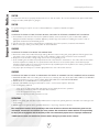
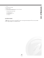
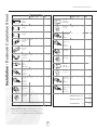
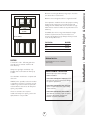
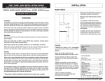
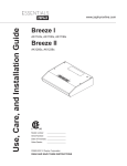
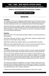
Use, Care, and Installation Guide
V E N T I L A T I O N
Breeze I, II
AK1124S, W
AK1100S, W, B
AK1136S, W, B
AK1200S, W, B
AK1236S, W, B
Model number:
Serial number:
0AK11-70001 REV. 09/04 © Zephyr Corporation.
www.zephyronline.com
www.zephyronline.com
INSTALLATION
Ducting Calculation Sheet ...................................................................................... 4
Mounting Height and Clearance ....................................................................... 5
Ducting ..................................................................................................................................... 6
Specifications ..................................................................................................................... 7
Preparing Electrical and Ducting ...................................................................... 8
Air Recirculating ............................................................................................................... 9
Mounting the Hood ........................................................................................................ 10
FEATURES & CONTROLS
Controls Overview .......................................................................................................... 11
MAINTENANCE
Cleaning .................................................................................................................................. 12
Lights ......................................................................................................................................... 12
TROUBLE SHOOTING ....................................................................................................... 13
WARRANTY ............................................................................................................................... 14
LIST OF ACCESSORIES/PARTS ............................................................................. 15
EXPLODED VIEW DIAGRAM ..................................................................................... 16-17
1
Table of Contents
SAFETY NOTICE ........................................................................................................................ 2
LIST OF MATERIALS ........................................................................................................... 3
Important safety Notice
www.zephyronline.com
CAUTION
To reduce risk of fire and to properly exhaust air, be sure to duct air outside - Do not vent exhaust air into spaces within walls,
ceilings, into attics, crawl spaces or garages.
CAUTION
For general venting use only. Do not use to exhaust hazardous or explosive materials and vapors..
WARNING
TO REDUCE THE RISK OF FIRE, ELECTRIC SHOCK, OR INJURY TO PERSONS, OBSERVE THE FOLLOWING:
a. The installation in this manual is intended for qualified installers, service technicians or persons with similar qualified
background. DO NOT attempt to install this appliance yourself. Injury could result from installing the unit due to lack of
appropriate electrical and technical background.
b. Use this unit only in the manner intended by the manufacturer, If you have questions, contact the manufacturer.
c. Before servicing or cleaning unit, switch power off at circuit breaker.
WARNING
TO REDUCE THE RISK OF A RANGE TOP GREASE FIRE:
a. Never leave surface units unattended at high settings. Boilovers cause smoking and greasy spillovers that may ignite. Heat
oils slowly on low or medium settings. The risk of self combustion is higher if the oil has been used several times.
b. Always turn hood ON when cooking at high heat or when cooking flaming foods.
c. Clean ventilating fans and filters frequently. Grease should not be allowed to accumulate on fan or filter. Old and worn filters
should be replaced immediately. Do not operate blowers when filters are removed, Never parts to clean without proper
instructions. Disassembly is recommended to be performed by a qualified personnel only. Refer to the cleaning instructions
or call our service center for any questions.
d. Use proper pan size. Always use cookware appropriate for the size of the surface element.
WARNING
TO REDUCE THE RISK OF INJURY TO PERSONS IN THE EVENT OF A RANGE TOP FIRE, OBSERVE THE FOLLOWING:
a. SMOTHER FLAMES with a close-fitting lid, cookie sheet, or metal tray, then turn off the burner. BE CAREFUL TO PREVENT
BURNS. If the flames do not go out immediately, EVACUATE AND CALL THE FIRE DEPARTMENT.
b. NEVER PICK UP A FLAMING PAN - You may be burned.
c. DO NOT USE WATER, including wet dishcloths or towels - a violent steam explosion will result.
d. Use an extinguisher ONLY if:
1. You know you have a class ABC extinguisher, and you already know how to operate it.
2. The fire is small and contained in the area where it started.
3. The fire department is being called.
4. You can fight the fire with your back to an exit.
OPERATIONS
a. Always leave safety grills and filters in place. Without these components, operating blowers could catch onto hair, fingers and
loose clothing.
b. NEVER dispose of cigarette ashes, ignitable substances or any foreign objects into blowers.
The manufacturer declines all responsibility in the event of failure to observe the instructions given here for
installation, maintenance and suitable use of the product. The manufacturer further declines all responsibility
for injury due to negligence and the warranty of the unit automatically expires due to improper maintenance.
* NOTE: Please check our website for revisions before doing any custom work or cutouts.
2
3 - Wire connector caps 18g
4 - Wood Screws 2”
4 - Wood Screws 1 1/2”
4 - Wood Screws 1”
4 - Washers
NO DUCTING IS INCLUDED
* Note: Zephyr recommends using 50LB EZ anchors if mounting hood onto drywall. These are not provided.
but are readily available of most hardware stores.
3
List of Materials
1 - Hood
2 - Light bulbs R16 40W
2 - Metallic Filters
1 - 3 1/4” x 10” rectangular starting collar with damper
1 - Hardware packet containing:
Installation - Ductwork Calculation Sheet
www.zephyronline.com
Equivalent number
length x used =
Duct pieces
Equivalent number
length x used =
Duct pieces
Total
Total
3 1/4” x 10” 1 Ft.
Rect.,
straight
x(
) =
Ft.
6” Round
wall cap
with damper
30 Ft.
x(
) =
Ft.
7” Round,
straight
1 Ft.
x(
) =
Ft.
6” Round,
roof cap
30 Ft.
x(
) =
Ft.
7” Round,
straight
1 Ft.
x(
) =
Ft.
6” round to
1 Ft.
3 1/4” x 10”
rect.
transition
x(
) =
Ft.
3 1/4” x 10” 15 Ft.
Rect. 900
elbow
x(
) =
Ft.
x(
) =
Ft.
3 1/4” x 10” 9 Ft.
Rect. 450
elbow
x(
) =
Ft.
6” round to
16 Ft.
3 1/4” x 10”
rect.
transition
900 elbow
7” Round,
900 elbow
15 Ft.
x(
) =
Ft.
3 1/4” x 10” 24 Ft.
Rect. 900
flat elbow
x(
7” Round,
450 elbow
9 Ft.
x(
) =
Ft.
3 1/4” x 10” 30 Ft.
Rect.
wall cap
with damper
x(
7” Round
wall cap
with damper
30 Ft.
x(
) =
Ft.
3 1/4” x 10” 5 Ft.
Rect. to
6” round
transition
x(
) =
Ft.
7” Round,
roof cap
30 Ft.
x(
) =
Ft.
3 1/4” x 10” 15 Ft.
Rect. to
6” round
transition
900 elbow
x(
) =
Ft.
7” round to
8 Ft.
3 1/4” x 10”
rect.
transition
x(
) =
Ft.
) =
Ft.
15 Ft.
x(
) =
Ft.
7” round to
15 Ft.
3 1/4” x 10”
rect.
transition
900 elbow
x(
6” Round,
900 elbow
6” Round,
450 elbow
9 Ft.
x(
) =
Ft.
Subtotal column 2 =
Ft.
Subtotal column 1 =
Ft.
Total ductwork
Ft.
) =
) =
Subtotal column 1 =
Ft.
Ft.
Ft.
Maximum Duct Length: For satisfactory air movement,
the total duct length of a 3 1/4” x 10” rectangular, 6” or 7”
diameter round duct should not exceed 100 equivalent feet.
4
=
Maximum mount height should be no higher than 30".
It is important to install the hood at the proper mounting
height. Hoods mounted too low could result in heat
damage and fire hazard; while hoods mounted too high
will be hard to reach and will loose its performance and
efficiency.
net width
MIN. 22” MAX 30”
If available, also refer to range manufacturer's height
clearance requirements and recommended hood
mounting height above range. Always check your local
codes for any differences.
Call Out Size
Net Width
24”
23 3/4”
30”
29 3/4”
36”
35 3/4”
Minimum Duct Size:
DUCTING
Rectangular- 3-1/4 x 10” minimum
(rear or top)
A minimum 3-1/4 x 10"rectangular duct
must be used to maintain maximum air
flow efficiency.
Always use rigid type metal ducts only.
Flexible ducts could restrict air flow by up
to 50%.
DAMAGE-SHIPMENT / INSTALLATION:
• Please fully inspect unit for damage
before installation.
Use calculation worksheet to compute total
duct work.
• If the unit is damaged in shipment, return
the unit to the store in which it was bought
for repair or replacement.
ALWAYS, when possible, reduce the number
or transitions and turns. If a reducer is used,
install a long reducer instead of a pancake
reducer. Reduce duct size as far away from
opening as possible.
• If the unit is damaged by the customer,
repair or replacement is the responsibility
of the customer.
If turns or transitions are required:
Install as far away from opening and as far
apart, between 2, as possible.
• If the unit is damaged by the installer (if
other than the customer), repair of replace
ment must be made by arrangement
between customer and installer.
5
Installation - Mounting Height & Clearance
Minimum mount height between range top to hood bottom should be no less than 22".
Installation - Ducting
www.zephyronline.com
WARNING FIRE HAZARD
NEVER exhaust air or terminate duct work into spaces between walls, crawl spaces, ceiling,attics or garages. All exhaust must
be ducted to the outside, unless using the recirculating option.
Use single wall rigid Metal ductwork only.
Fasten all connections with sheet metal screws and tape all joints w/ certified Silver Tape or DuctTape.
Some Ducting Options:
cabinet
3 1/4" x 10" rear discharge
w/side wall gravity damper
air recirculation
Roof Cap
3 1/4" x 10"
vertical discharge
roof cap
6
1 - 31/32"
)
9 - 1/16"
7 - 5/8"
")
1 - 31/32"
1 - 31/32"
10 - 53/64"
.3
78
7
1 - 31/32"
12 - 13/64"
8 - 20/32"
9 - 1/16"
21 - 37/64"
9 - 1/16"
1 - 31/32"
1 - 31/32"
33 - 55/64" (36")
27 - 7/8" (30")
22 - 3/64" (24")
9 - 1/16"
Installation - Specifications
.3
78
12 - 13/64"
36"
30"
24"
Installation - Preparing Electrical and Ducting
www.zephyronline.com
1. Remove filters.
2. Remove cover from junction box to gain
access to the electrical wiring.
3. If using a cable lock (not provided) pry
open the desired electrical knockout, either
on the top or the back. Feed the wires
through the 3/4” cable lock. Note: Some
local coded require the use of a cable lock,
Duct
Measurements
check your
local
coded for this information.
4. If using hood in air recirculation mode,
skip steps 4 and 5 pry open the desired
3 1/4” x 10 ducting knockout, either
horizontal or vertical.
Wall
Rear
Cable
lock example
Cable lock
9 1/2" 9"
Front
7"
8"
(min.cutout)
5. Attach the 3 1/4” X 10 starting collar
with damper to the duct opening you
exposed.
8
An air recirculation kit (optional) must be
purchased in order to use the hood in air
recirculation mode.
1. Attach each of the (2) spring loaded
clips to the safety grill body. Do this by
inserting the screw to the spring and into
the bracket. Then screw it into the safety
grill body.
2. Insert the carbon filter into the carbon
filter holder and place it over the safety grill.
3. Secure the carbon filter holder to the
safety grill body by slightly lifting and
twisting the spring loaded clip. Make sure it
presses against the lip of the carbon filter
holder securely.
4. Unscrew and remove the air diverter
plate.
5. Finally, remove the cover plate at the
front of the hood on top. Replace it with the
air recirculation cover plate.
9
Installation - Air Recirculating
* If you are ducting the air out of your home, skip these steps.
Installation - Mounting the Hood
www.zephyronline.com
ELECTRICAL - WARNING
All Electrical work must by performed by qualified
electrician or person with similar technical know how
and background.
For personal safety, remove house fuse or open circuit
breaker before beginning installation.
Do not use extension cord or adapter plug with
this appliance.
Follow National electrical codes or prevailing local
codes and ordinances.
Electrical Supply:
This appliance requires a 120V 60Hz electrical supply.,
and connected to an individual, properly grounded branch
circuit, protected by a 15 or 20 ampere circuit breaker or
time delay fuse. Wiring must be 2 wire w/ ground. Please
refer to Electrical Diagram labeled on product.
1. Temporarely position the hood in the
desired mounting location. Measure and
mark the mounting holes, duct and electrical access locations with a pencil. Remove
hood and drill/cut out the requirred openings for duct and electrical access.
2. Attach house electrical wiring to
hood wiring. Make sure the power source
is turned off before working with any
electrical wiring.
3. Hang hood from mounting screws
provided. Slide hood toward wall until
mounting screws are engaged in narrow
end of keyholes. Tighten mounting screws
securely. CAUTION: Do not push on safety
grill when installing, this may result in
damage to the motor.
4. Attach duct work. Use aluminum duct
tape to make joints secure and air tight.
NOTE: This step is not necessary if hood is
in air recirculation mode.
5. If not already done, install light bulbs by
screwing in clockwise.
10
1 Blower On/Off/Speed Selection
III
II
I
2 Lights On/Off/Dim
II
0
I
0
1 Blower On/Off/Speed Selection
This switch turns the blower on and off and controls the speed selection.
0 is off, I is low speed, II is medium speed and III is high speed.
2 Lights On/Off/Dim
0 is off, I is bright, II is dim.
Breeze II, AKI2XX
4
1
3
III
II
2
I
1 On/Off
This button turns the motors on and off. It also shuts off power to the whole hood.
If the lights are on and this button is pushed, they will also turn off.
2 Lamp
This button turns the lights on, off and also dims them. Press once to turn them on bright,
again for dim and one more time to shut them off.
3 Speed
This button will change the speed setting of the motors. By pushing it you will change the
speeds from low, to medium, to high.
4 Delay Off
This button will put the hood into delay off mode. When pushed, the hood will switch to the
lowest speed and the entire hood will shut down after 5 minutes.
11
Features & Controls - Controls Overview
Breeze I, AKIIXX
Maintenance - Cleaning and Replacing Light Bulbs
www.zephyronline.com
Aluminum Mesh Filters:
Clean frequently using hot water and a mild, non abrasive detergent. Filters are dishwasher safe.
Carbon Filters:
Clean carbon filters holder frequently with a damp cloth and mild detergent. DO NOT immerse carbon filter in water or put in
dishwasher. The carbon filters should be replaced every 4 to 6 months under normal use.
Hood Surface:
Remove filters. Use a damp cloth and a mild detergent to wipe all residue-laden surfaces. Use care when cleaning fan blades,
it must not become bent or misaligned. DO NOT ALLOW WATER TO ENTER MOTOR. Make sure all surfaces are completely
dry before re-installing filters and using hood.
Replacing Light Bulbs:
CAUTION: Light bulbs become extremely hot when turned on. DO NOT touch bulbs until switched off and cooled.
Touching hot bulbs may cause serious burns.
Hood comes with (2) R16 40W incandescent bulbs. You may also use (2) PAR20 35W or 50W halogen light bulbs.
(purchased separately)
Remove bulb by unscrewing counter-clockwise. Use a suction cup or rubber/latex glove to grip the bulb if removing bulb
is difficult.
12
Check if unit has been plugged in, make sure that all power has been
turned back on and all electrical wiring are properly connected.
2. Light is on but blowers are not
turning at all or seems to be
scraping on something.
Blower blade unit might have been mounted too low and scraping
the bottom or jammed. Loosen hex screw on blade unit and adjust to
proper height.
3. When blowers are on,
something seems to be loose
and spinning around inside.
There might have been foreign particles left within the discharge
opening or rocks, leaves, branches, etc. that might have fell in from
old duct work. Disconnect duct work to inspect and remove any
foreign particles.
4. Vibration when blowers are on
Unit might not have been secured properly on cabinet. Or cabinet
might need to be further secured into studs on wall.
5. Blowers noise
Our blowers are designed to perform up to 850 cfm. A properly
functioning motor itself should be relatively quiet. Nevertheless, due
to vacuum created by the suction, noise level up to 6 sones will be
generated when both blower unit is turned on at its maximum speed.
Employing low speeds will suffice moderate cooking such as steaming, broiling etc.
6. Light is not working
Light bulb might need to be replaced. On some instances, the fragile
bulb could have been damaged during the shipping process.
Replace light bulb.
7. Blowers seemed weak
Check duct size used, duct size should be at least 3 1/4” x 10”.
Range hood WILL NOT function properly with the insufficient
duct size.
Check if duct is clogged or if dumper unit is not opening properly. A
tight mesh on a side wall cap unit might also cause restriction to the
air flow.
Use a damper type sidewall cap.
Reduce the number of elbows and length of duct work or increase
duct size.
Check if all joints are properly connected, sealed and taped.
8. Cooking fumes and smoke
dissipates before it reaches
the blower.
Check if unit is installed at the recommended height. The range hood
should also be able to cover the entire cooking area from left to right
and most areas from rear to front.
Open doors and windows might also distract air flow before it reaches the blowers.
Make sure blowers are on high speed for heavy cooking.
13
Trouble Shooting
1. Upon completion of installation
nothing works.
Warranty
www.zephyronline.com
TO OBTAIN SERVICE UNDER WARRANTY:
or any Service Related Questions, please call:
Staple your receipt here.
Proof of the original purchase
date is needed to obtain service
under the warranty.
1-888-880-8368
TO OBTAIN SERVICE UNDER WARRANTY: You must present proof of original purchase date.
Please keep a copy of your dated proof of purchase (sales slip) in order to obtain service under warranty.
One Year Service Repair Warranty:
For one year from date of original purchase, we will provide free of charge, service labor to repair any failed parts or
components due to manufacturing defects.
Ten Years Parts Warranty:
For ten years from date of original purchase, we will provide free of charge, nonconsumable replacement parts or
components that failed due to manufacturing defects. Consumable parts not covered by this warranty include: Light Bulbs,
Metal and Carbon Filters.
Who is Covered:
This warranty is extended to the original purchaser for products purchased for ordinary home use in the 48 mainland states,
Hawaii and Washington D.C. In Canada and Alaska, this warranty is Limited. There might be costs associated with
shipping the products to our designated service locations or you might need to pay service technician's travel costs, to have
the appliance repaired in-home.
This Warranty will be Voided when:
Product damaged through negligence, misuse, abuse, accident. Improper installation and failure to follow installation instructions. When product is used commercially or other than its intended purpose. Damaged because of improper connection with
equipment of other manufacturers. Repaired or modified by anyone other than Zephyr's Authorized Agents.
What is Not Covered:
Consumable parts such as light bulbs, filters, and fuses. Services outside of service area and the labor cost incurred in
connection with the removal, shipping and reinstallation cost, nor does it cover any other contingent expenses. The natural
wear of finish, and wear due to improper maintenance, use of corrosive and abrasive cleaning products, pads, and oven
cleaner products. Chips, dents or cracks due to abuse, misuse, freight damage, or improper installation. Service trips to your
home to teach you how to use the product. Damage of product caused by accident, fire, floods or act of God.
This warranty is valid in the United States and Canada. It is non-transferable and applies only to the original purchaser and does not extend to subsequent owners of this product. Any applicable implied warranties, including the warranty of merchantability, are limited in duration to a period of express warranty as provided herein beginning with the date of original purchase at retail
and, no warranties, whether express or implied, shall apply to this product thereafter.
Have your product proof of purchase with date ready for warranty issues.
Or write to:
Zephyr Corporation
Service and Warranty Department
395 Mendell Street
San Francisco, CA 94124
14
Part#
Light Bulb (R16 40W)
Light Bulb (PAR20 35W)
Telescopic Back Splash 30” SS
AK0710
Telescopic Back Splash 36” SS
AK0716
Air Recirculation Kit (w/carbon filter)
0AK11-21001
Carbon Filter Replacement
0AK11-20001
Aluminum Replacement Filters, 24”, 30”
0AK11-22001
Aluminum Replacement Filters, 36”
0AK11-22002
To order parts, visit us online at : www.zephyronline.com and go to the parts store.
Or call us at : 888-880-8368
15
List of Accessories and Parts
Description
Exploded View Diagram
www.zephyronline.com
16
Factory
Description “From Exploded View”
17
Per Hood
Exploded View Diagram
Part