1
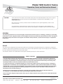
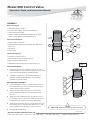
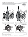
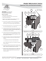
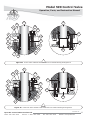
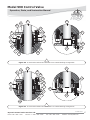
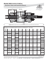
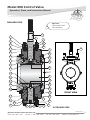
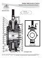
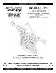
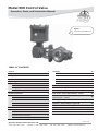
Model 590 Control Valve
Operation, Parts, and Instruction Manual
Figure 1
6 Inch 590 with DFRP-112
TABLE OF CONTENTS
General
2
Scope
2
Assembly
Stud Installation
17
Safety Caution
2
Ball and Shaft Assembly
17
Specifications
3
Ball Seal Installation
22
Unpacking
4
Body Outlet Installation
22
Installation
4
Flow Ring Installation
24
17
Valve Weight - Table 2
5
Live Loaded Packing
25
Line Bolt Placement - Figure 3
5
Actuator Mounting
25
Air Piping
5
Travel Adjustment
28
Periodic Inspection
8
Seal Carrier Torque Requirements - Table 7
28
Maintenance
8
8
Shaft Retainer & Retainer Screw Torque
Requirements - Table 8
28
9
Ball Support Post and Retainer Removal Tool
29
Shaft Seal Maintenance
- Follower Shaft
- Drive Shaft
Ball Seal Maintenance
10
Actuator / Valve Positions - Figure 36
30
11
Single Seal Cross Section - Figure 37
31
Actuator Removal
12
Dual Seal Cross Section - Figure 38
32
Disassembly
12
Parts
33
Body Outlet / Seal Protector Ring
13
Model Builder
40
Outboard Shaft Disassembly
14
Inboard Shaft Disassembly
15
P-590M0415A
Dyna-Flo Control Valve Services Ltd.
Phone: 780
•
469
•
4000
Toll Free: 1
•
866
•
396
•
2356
Fax: 780
•
469
•
4035
Website: www.dynaflo.com
1
Model 590 Control Valve
Operation, Parts, and Instruction Manual
NOTICE
These instructions are meant to be used with the Dyna-Flo 590 Technical Bulletin as they refer to Figures
and Tables therein. If you do not have the Technical Bulletin, contact Dyna-Flo immediately, or visit
www.dynaflo.com
Each control valve is factory checked. Check the calibration for the specific application, before a valve
is put into service.
It is the intention of this document to provide users with an accurate guide for safe installation and
maintenance of the 590 Control Valve. Revisions and updates are available at above mentioned website.
GENERAL
The following instructions are to be thoroughly reviewed and understood prior to installing, operating or performing
maintenance on this equipment. Work on this equipment should be performed by experienced personnel. Throughout
the manual, safety and caution notes appear and must be strictly followed, to prevent serious injury or equipment
malfunction.
SCOPE
The control valve configuration and construction materials were selected to meet particular pressure, temperature, and process
conditions. Some material combinations are limited in their pressure and temperature ranges. Do not apply any other conditions to
the valve without first contacting your Dyna-Flo sales office.
This manual is written to be a practical and useful guide maintaining the Dyna-Flo 590 Control Valve.
SAFETY CAUTION
Only well trained experienced technicians should perform these procedures. Use safe work practices and lock out
procedures when isolating valves and actuators. It is also important to wear the proper protective equipment when
performing any installation or maintenance activity. Use only parts and materials rated for the process being used,
operating conditions, and environmental conditions products will be used in.
To avoid personal injury or installation damage as a result of the sudden release of process pressure or damage to
equipment, do not install the valve assembly where service conditions could exceed the limits stated in this manual,
sales bulletin or on the equipment nameplates. Use government codes, accepted industry standards and good piping
practices, and select proper pressure-relieving equipment for protection of your installation. Always be aware of
flammable process and instrument gas.
Always be aware of the hazards of actuators, especially spring-loaded actuators. Be sure that the actuator is
de-energized or in the failed position before performing any maintenance procedure.
These valves have dangerous pinch points. Never put your hands inside the valve unless you are certain that the ball
cannot rotate.
P-590M0415A
Dyna-Flo Control Valve Services Ltd.
Phone: 780
•
469
•
4000
Toll Free: 1
•
866
•
396
•
2356
Fax: 780
•
469
•
4035
Website: www.dynaflo.com
2
Model 590 Control Valve
Operation, Parts, and Instruction Manual
SPECIFICATIONS
Available Valve Configurations
The 4”, 6”, 8”, 10”, 12”, and 16” flangeless valves will mate
ASME Class 600 and 900. See Table 1 of Sales Bulletin.
Actuator Mounting
Right-hand, or Left-hand (as viewed from seal end of valve).
In one of 4 positions (12 (Std.), 3, 6, and 9 o’clock) with
respect to the valve body in a horizontal pipe.
Rotary ball valve assembly available with:
• Single Ball Seal
Maximum Ball Rotation
90 degrees.
• Dual Ball Seal
• Flow Ring
Maximum Inlet Pressure
4 through 12 inch valve body consistent with Class 600 and
900 ASME B16.34.
16 inch valve body consistent with Class 600 ASME B16.34.
Maximum Allowable Shutoff Pressure Drop
Single Seal and Dual Seal: See Figure 10 of Sales Bulletin.
Flow Ring: Limited by the pressure/temperature rating of
the valve body.
Shutoff Classification
Single Seal and Dual Seal: 0.0001% of maximum valve
capacity (less than 1% of Class IV, ANSI/FCI 70-2 and
IEC 60534-4).
Flow Ring: 1% of maximum valve capacity
Flow Characteristic
Modified Equal Percentage
Valve Dimensions
See Figure 4 for valve diagram.
Material Temperature Capabilities
See Tables 5 & 6 for valve dimensions.
Single Seal and Dual Seal:
-50oF to 180oF (-46oC to 82oC) LCC Body.
-20oF to 180oF (-29oC to 82oC) WCC* Body.
-20oF to 180oF (-29oC to 82oC) CF8M Body.
Approximate Valve Weight
See Table 2.
Flow Ring with Fluorocarbon O-Rings:
-50oF to 400oF (-46oC to 204oC) LCC Body.
-20oF to 400oF (-29oC to 204oC) WCC* Body.
-20oF to 400oF (-29oC to 204oC) CF8M Body.
Valve Sizing Coefficients
See Table 9 of Sales Bulletin.
For more information and other options contact your Dyna-Flo
sales office.
*Note: WCC body material is special order.
Construction Materials
See Parts section of manual for material listings. Contact your
Dyna-Flo sales office for more information and other options.
Table 1
Model 590 Available Valve Size and ASME Rating
Valve Size Inch
Flow Direction (See Figures 37 & 38)
Single Seal Configuration: Forward flow only.
Dual Seal Configuration: Required for bidirectional flow
shutoff.
Flow Ring Configuration: Forward or reverse flow.
4
600
900
6
600
900
8
600
900
10
600
900
12
600
900
16
600
P-590M0415A
Dyna-Flo Control Valve Services Ltd.
Phone: 780
•
469
•
4000
Toll Free: 1
•
866
ASME Rating
•
396
•
2356
Fax: 780
•
469
•
4035
Website: www.dynaflo.com
3
Model 590 Control Valve
Operation, Parts, and Instruction Manual
UNPACKING VALVE FROM SHIPPING
CONTAINER
Figure 2
Suggested Lifting
Strap Placement
Special Tools Required:
• Properly Rated Lifting Straps (2 – 4 Straps) See Table 2 for
valve weights.
LIFTING STRAP
LIFTING STRAP
• Lifting Device (Example: Crane)
Check the packing list, verify that the list includes all the
materials in the shipping container before unpacking.
Place the lifting straps around the neck of the actuator and
valve body (See Figure 2). Straps should be placed to avoid
damage to tubing and other mounted accessories.
INSTALLATION
Installation Steps:
Before You Begin:
1
Clean dirt, welding chips, scale, or other foreign material
from the line and flange surfaces.
2
Valve may be installed in any orientation, although to
reduce stress and wear on valve assembly it is
recommended that valve be installed with the valve shaft
(Key 17) horizontal to the ground.
3
For Single Seal Construction
Center the valve in-line as indicated by flow arrow (See
Figure 37 & 38), standard flow direction has the seal
protector ring (Key 26) facing up stream.
• Read the General and Scope section of this manual (Page 2).
• Read Safety Caution (Page 2).
• Place the valve into the OPEN position, this helps to prevent
damage to the valve ball (Key 2) during installation.
• Sudden movement of actuator can cause damage or injury.
It helps to have the actuator de-energized as long as the
valve remains in the OPEN position.
• Use safe work practices and lock out procedures before
placing valve in-line.
For Dual Seal Construction
Center the valve in-line so the flow direction with the
highest pressure matches the direction of the flow arrow
(see Figure 36, 37, 38).
Parts Required:
• Flange Studs (Key 51) Note: Flange Studs will need to span
the distance from one line flange, across the valve body, and
though the other line flange. (See Table 3 & 4 for stud
lengths & Figure 3 for stud placement)
• Long Cap Screws (Key 53) Note: Long Cap Screws pass
through the line flanges and thread directly into the valve
body. Long Cap Screws will be required for the outlet side of
the valve for single seal valve configurations. (See Table 3 &
4 for cap screw length and Figure 3 for cap screw placement)
• Short Cap Screws (Key 52) Note: Short Cap Screws pass
through the line flanges and thread directly into the valve
body. (See Table 3 & 4 for cap screw length and Figure 3 for
cap screw placement)
4
Install the line flange gaskets.
5
Apply anti-seize compound (Key A) to the threads of the
flange studs (Key 51) and cap screws (Keys 52 & 53).
6
Tighten the flange studs and cap screws in even
increments in a crisscross pattern until the correct line bolt
torque specification is reached.
• Appropriate Line Flange Gaskets.
P-590M0415A
Dyna-Flo Control Valve Services Ltd.
Phone: 780
•
469
•
4000
Toll Free: 1
•
866
•
396
•
2356
Fax: 780
•
469
•
4035
Website: www.dynaflo.com
4
Model 590 Control Valve
Operation, Parts, and Instruction Manual
OUTLET SIDE (BACK OF VALVE)
INLET SIDE (FRONT OF VALVE)
KEY 26 - SEAL PROTECTOR
RING
KEY 33 - BODY OUTLET
KEY 51 - FLANGE STUDS
KEY 52 - SHORT CAP SCREWS
KEY 53 - LONG CAP SCREWS
Figure 3 Line Bolt Placement Example (10 Inch 590 Shown) See Figure 4 for alternative view
INSTALLATION (Continued)
AIR PIPING
WARNING:
Property damage, environmental harm, and personal injury can result from the use of supply gas other than clean,
non-corrosive, oil and moisture free air. Do not exceed the supply pressure indicated on the serial plate located on the actuator.
Before You Begin:
Note: Standard actuators accept ¼” (6 mm) NPT connections.
• Refer to the appropriate actuator instruction manual when necessary.
Piping Installation Steps:
1
Use 3/8” (outside diameter) tubing (or equivalent) for air lines.
2
Install the required line vents, valves, drains, seals, and filters to the actuator.
Table 2
Model 590 Approximate Valve Weight
Valve Size Inch
lb (Kg)
4
160 (73)
6
290 (132)
8
490 (222)
10
760 (345)
12
950 (431)
16
1700 (771)
P-590M0415A
Dyna-Flo Control Valve Services Ltd.
Phone: 780
•
469
•
4000
Toll Free: 1
•
866
•
396
•
2356
Fax: 780
•
469
•
4035
Website: www.dynaflo.com
5
Model 590 Control Valve
Operation, Parts, and Instruction Manual
J
50
H
F G
E
S
D
C
A
B
L
52
51
53
I
K
FLOW
Figure 4 Valve Dimensions and Line Bolting
Table 3
Model 590 Valve Dimensions - Flange Bolting - Class 600 Inch
Dimensional Reference
Valve
Size
RF
I
QTY.
K
RTJ
QTY.
L
QTY.
I
K
QTY.
QTY.
L
QTY.
TPI
4”
-
-
-
-
13.50
8
-
-
-
-
14.50
8
7/8 - 9
6”
4.63
4
4.63
4
16.25
8
4.88
4
4.88
4
16.25
8
1-8
8”
5.50
4
5.38
4
17.50
8
5.63
4
5.50
4
17.75
8
1-1/8 - 8
10”
6.25
4
6.38
4
20.75
12
6.50
4
6.50
4
20.75
12
1-1/4 - 8
12”
7.00
4
6.00
4
23.00
16
7.00
4
6.50
4
23.00
16
1-1/4 - 8
16”
7.75
4
7.75
4
26.00
16
8.00
4
8.00
4
26.50
16
1-1/2 -8
P-590M0415A
Dyna-Flo Control Valve Services Ltd.
Phone: 780
•
469
•
4000
Toll Free: 1
•
866
•
396
•
2356
Fax: 780
•
469
•
4035
Website: www.dynaflo.com
6
Model 590 Control Valve
Operation, Parts, and Instruction Manual
Table 4
Model 590 Valve Dimensions - Flange Bolting - Class 900 Inch
Dimensional Reference
Valve
Size
RF
RTJ
K
QTY.
L
QTY.
4
4.88
4
14.75
5.00
4
6.00
4
5.00
4
5.88
4
10”
6.63
12”
7.25
4
6.75
4
6.63
I
QTY.
4”
4.88
6”
8”
TPI
I
QTY.
K
QTY.
L
QTY.
4
4.88
4
5.13
4
14.75
4
1-1/8 - 8
17.50
8
5.00
4
5.25
4
17.50
8
1-1/8 - 8
19.00
8
6.00
4
6.13
4
19.00
8
1-3/8 - 8
4
21.50
12
6.63
4
6.88
4
21.50
12
1-3/8 - 8
4
24.00
16
7.25
4
7.50
4
24.00
16
1-5/8 - 8
Table 5
Model 590 Valve Dimensions Inch (mm)
Dimensional Reference
Valve Size
S
B
Spline Diameter
Shaft Diameter
C
D
E
(Bore Diameter)
4”
8.19 (208)
1.25 (31.8)
1.25 (31.8)
6.38 (162)
7.75 (197)
3.00 (76.2)
6”
14.00 (356)
2.00 (50.8)
2.00 (50.8)
7.62 (194)
9.38 (238)
4.00 (101.6)
8”
14.00 (356)
2.50 (63.5)
2.50 (63.5)
10.62 (270)
12.88 (327)
6.00 (152.4)
10”
14.00 (356)
2.75 (69.9)
2.50 (63.5)
11.31 (287)
13.50 (343)
7.38 (187.5)
12”
14.00 (356)
3.00 (76.2)
2.50 (63.5)
12.75 (324)
15.00 (381)
9.00 (228.6)
18.50 (470)
2.50 (63.5)
20.00 (508)
3.50 (88.9)
4.00 (101.6)
15.44 (392)
18.12 (460)
11.50 (292.1)
16”
ASME Class: 600 and 900
• Envelope Dimensions are + / - 0.25 in. (6.4 mm)
• Face to Face Tolerance Per ASME
Table 6
Model 590 Valve Dimensions Continued Inch (mm)
Dimensional Reference
Valve Size
4”
A
F
G
H
J
7.62 (194)
11.00 (279)
9.25 (235)
1.81 (46)
5/8 - UNC
6”
9.00 (229)
12.88 (327)
10.75 (273)
2.00 (51)
3/4 - UNC
8”
9.56 (243)
16.25 (413)
13.25 (337)
3.00 (76)
7/8 - UNC
10”
11.69 (297)
17.50 (445)
13.25 (337)
3.00 (76)
7/8 - UNC
12”
13.31 (338)
19.00 (483)
13.25 (337)
3.00 (76)
7/8 - UNC
16”
15.75 (400)
24.12 (613)
21.00 (533)
5.00 (127)
1-1/4—8UN
ASME Class: 600 and 900
• Envelope Dimensions are + / - 0.25 in. (6.4 mm)
• Face to Face Tolerance Per ASME
P-590M0415A
Dyna-Flo Control Valve Services Ltd.
Phone: 780
•
469
•
4000
Toll Free: 1
•
866
•
396
•
2356
Fax: 780
•
469
•
4035
Website: www.dynaflo.com
7
Model 590 Control Valve
Operation, Parts, and Instruction Manual
PERIODIC INSPECTION
MAINTENANCE
Special Equipment Required:
Note: Shaft seals or live loaded packing and ball seals (Key 30)
should all be inspected frequently for leaks, wear and
damage. Maintenance to the shaft seals or live loaded packing
can be made while the valve is still in-line, the actuator must
be removed for drive shaft (Key 17) seal/pacing maintenance
(See Page 12 for Actuator Removal instructions).
• Bypass or block valves.
Before You Begin:
• Read Safety Caution (Page 2).
• Use safe work practices and lock out procedures.
• Disconnect supply lines (air or gas), electric power, or control
signal to the actuator. Sudden movement of actuator can
cause damage or injury, make sure actuator will not operate.
• Vent any pneumatic actuator loading pressure and relieve
any actuator spring preload if present.
• Relieve process pressure and drain the process fluid from up
and down stream of valve.
• Be aware of potentially hazardous process material that may
be present in-line and in-valve. Isolate the valve from
process pressure. Use a bypass or block valve if necessary,
or completely shut off the process. For dual seal valves,
relieve internal pressure by removing the pipe plug (Key 37).
See Figure 38 on Page 32.
Note: Perform ball seal (Key 30) maintenance when the control
valve will not properly shut off. Ball seal maintenance can be
performed without removing the actuator from the valve. Ball
seal maintenance cannot be performed with the valve in-line.
When removing the valve from pipe line be sure it is in the
OPEN position, verify the valve is open using the indicator
scale (Key 24) before removing from line.
Note: When testing the seal integrity of the valve using the
pipe plug port (dual seal configuration), it is recommended that
the pipe plug (Key 37) be replaced by a hand valve. A hand
valve will allow valve pressure to be relieved safely during
seat leak rate testing. See Figure 38 for pipe plug location.
Before You Begin:
Inspection Steps:
• Read Safety Caution (Page 2).
1
Check for visible signs of leakage around all seal and
gasket areas.
• Determine if valve has shaft seals or live loaded packing
(See Figures 31 & 37).
2
Check the valve for damage, especially damage caused by
corrosive fumes or process drippings.
• Determine if valve is single seal or dual seal (See Figures 37
& 38).
3
Clean and repaint the areas as required.
• Follow Steps 2 – 5 of PERIODIC INSPECTION Before you
begin.
4
Ensure all accessories, mounting brackets, and fasteners
are secure.
SHAFT SEAL MAINTENANCE
5
Clean any dirt and foreign material from the valve shaft
(Key 17).
Note: It is recommended that the follower shaft seal and the
drive shaft seal be replaced at the same time. The actuator
must be removed for drive shaft seal maintenance. For live
loaded packing see Page 25.
Special Tools Required:
• Mechanics Pick Set
Lubricants Required:
• Anti-Seize Compound (Key A)
• Silicone-based O-Ring Compound (Key B)
• White Petroleum Grease (Key C)
P-590M0415A
Dyna-Flo Control Valve Services Ltd.
Phone: 780
•
469
•
4000
Toll Free: 1
•
866
•
396
•
2356
Fax: 780
•
469
•
4035
Website: www.dynaflo.com
8
Model 590 Control Valve
Operation, Parts, and Instruction Manual
MAINTENANCE (Continued)
Follower Shaft Seal (Outboard Seal)
Reassembly (See Figure 5)
SHAFT SEAL MAINTENANCE (Continued)
Follower Shaft Seal (Outboard Seal)
Disassembly (See Figure 5)
1
Remove the outboard seal carrier nuts (Key 3).
2
Remove the outboard seal carrier (Key 6). Note: The seal
carrier o-ring (Key 7) may stick to the seal carrier and get
removed at the same time (Figure 5.1), remove the o-ring
after.
3
Using a mechanics pick set, carefully remove the backup
ring (Key 8) and seal ring (Key 9).
4
Inspect all parts for damage, including the follower shaft
(Key 21), damaged shafts must be replaced or repaired to
avoid leaks (See Page 12 for Disassembly Instructions).
Replace any damaged parts with new parts as necessary.
Lubricate the seal ring (Key 9) with white petroleum
grease (Key C) and install.
2
Lubricate the backup ring (Key 8) with white petroleum
grease (Key C) and install.
3
Lubricate the seal carrier o-ring (Key 7) with siliconebased compound (Key B) and install it onto the outboard
seal carrier (Key 6).
4
Find the locator pin (Key 22), install the seal carrier (Key
6) onto the follower shaft (Key 21) making sure that the
locator pin is in alignment with the orientation hole in the
seal carrier.
5
Apply anti-seize compound (Key A) to the threads of the
seal carrier studs (Key 4).
6
Thread the seal carrier nuts (Key 3) onto the seal carrier
studs (Key 4) and tighten the nuts according to the torque
requirements in Table 7 (Page 28).
Figure 5.1
6
8
9
C
1
6
C
DIRECTION OF
INTERNAL PRESSURE
21
A
C
4
9
7
B
3
6
22
8
C
Figure 5 Follower Shaft Seal (Outboard Seal) Maintenance Diagram
P-590M0415A
Dyna-Flo Control Valve Services Ltd.
Phone: 780
•
469
•
4000
Toll Free: 1
•
866
•
396
•
2356
Fax: 780
•
469
•
4035
Website: www.dynaflo.com
9
Model 590 Control Valve
Operation, Parts, and Instruction Manual
17
MAINTENANCE (Continued)
3
SHAFT SEAL MAINTENANCE (Continued)
Drive Shaft Seal (Inboard Seal)
1
Remove the actuator (See Page 12 for Actuator Removal
instructions).
2
Remove the inboard seal carrier nuts (Key 3).
3
Remove the inboard seal carrier (Key 5). Note: The seal
carrier o-ring (Key 7) may stick to the seal carrier and get
removed at the same time (Figure 6.1), remove the o-ring
after.
4
Using a mechanics pick set, carefully remove the backup
ring (Key 8) and seal ring (Key 9).
5
4
5
Disassembly (See Figure 6)
Figure 6.1
Inspect all parts for damage, including the drive shaft
(Key 17), damaged shafts must be replaced or repaired to
avoid leaks (See Page 12 for Disassembly Instructions).
Replace any damaged parts with new parts as necessary.
5
8
9
C
DIRECTION OF
INTERNAL PRESSURE
Reassembly (See Figure 6)
3
1
Lubricate the seal ring (Key 9) with white petroleum
grease (Key C) and install.
2
Lubricate the backup ring (Key 8) with white petroleum
grease (Key C) and install.
3
Lubricate the seal carrier o-ring (Key 7) with siliconebased compound (Key B) and install it onto the inboard
seal carrier (Key 5).
4
Install the seal carrier (Key 5) over the drive shaft (Key
17) and into the bore.
C
5
Apply anti-seize compound (Key A) to the threads of the
seal carrier studs (Key 4).
9
6
Thread the seal carrier nuts (Key 3) onto the seal carrier
studs (Key 4) and tighten the nuts according to the torque
requirements in Table 7 (Page 28).
7
C
7
8
B
C
17
4
10 - DO
NOT REMOVE
A
Re-mount the actuator to the valve. See the Actuator
Mounting instructions on Page 25, refer to the appropriate
actuator instruction manual for more information.
Figure 6 Drive Shaft Seal (Inboard Seal)
Maintenance Diagram
P-590M0415A
Dyna-Flo Control Valve Services Ltd.
Phone: 780
•
469
•
4000
Toll Free: 1
•
866
•
396
•
2356
Fax: 780
•
469
•
4035
Website: www.dynaflo.com
10
Model 590 Control Valve
Operation, Parts, and Instruction Manual
MAINTENANCE (Continued)
Reassembly (See Figure 7)
Note: If the ball seal (Key 30) was damaged and replaced, it
will be necessary to re-adjust the ball deflection of the valve.
Ball seal repair kits will included extra shims for adjustment
purposes. For instructions on Ball Deflection see Step 18 of
Ball and Shaft Assembly on Page 20.
BALL SEAL MAINTENANCE
Before You Begin:
• Read Safety Caution (Page 2).
• Refer to Maintenance Notes (Page 8).
1
Place the shims (Key 31) over the ball (Key 2).
2
Set the ball seal (Key 30) over the ball (Key 2), make sure
it is centered.
3
Lubricate the seal protector o-ring (Key 29) with siliconebased o-ring compound (Key B) and place it in the valve.
4
The seal protector ring (Key 26) is equipped with
threaded holes to attached eye hooks for lifting. Carefully
lift and lower the seal protector ring into position.
5
Install the seal protector cap screws (Key 25) and tighten
them evenly in a crisscross pattern until snug.
6
For Dual Seal construction, repeat Steps 1 to 5 above for
the other side of the valve.
Disassembly (See Figure 7)
1
If the valve is still in-line, make sure that the valve is in
the OPEN position before it is removed from the pipe line.
Remove the valve from pipe line.
2
Remove seal protector ring cap screws (Key 25).
3
Remove the seal protector ring (Key 26).
4
Remove the seal protector ring o-ring (Key 29).
5
Remove the ball seal (Key 30).
6
Remove the shims (Key 31).
7
For Dual Seal construction, repeat Steps 2 to 6 above for
the opposite side of the valve.
8
Inspect all parts (especially sealing surfaces) for damage,
replace parts with new parts as necessary.
26
29
25
B
30
31
1
Figure 7 Ball Seal Maintenance Diagram
P-590M0415A
Dyna-Flo Control Valve Services Ltd.
Phone: 780
•
469
•
4000
Toll Free: 1
•
866
•
396
•
2356
Fax: 780
•
469
•
4035
Website: www.dynaflo.com
11
Model 590 Control Valve
Operation, Parts, and Instruction Manual
ACTUATOR REMOVAL
DISASSEMBLY
Note: Actuator removal does not require that the valve be
removed from the pipeline.
Before You Begin:
• Read Safety Caution (Page 2).
• Use safe work practices and lock out procedures.
Before You Begin:
• Remove the actuator from the valve (See Actuator Removal
Instructions, Page 12).
• Read Safety Caution (Page 2).
• Use safe work practices and lock out procedures.
• Disconnect supply lines (air or gas), electric power, or control
signal to the actuator. Sudden movement of actuator can
cause damage or injury, make sure actuator will not operate.
• Vent any pneumatic actuator loading pressure and relieve
any actuator spring preload if present.
Removal Steps:
1
Refer to the appropriate actuator instruction manual for
more information regarding the actuator being removed.
2
If the valve has been removed from the pipeline, place
the valve assembly on a flat work surface that can
support the weight. It helps to have block placed under the
valve to raise the valve off the work surface and allow for
free ball movement (See Figure 8.1).
3
The actuator lever is clamped onto the valve shaft (Key
17), loosen the actuator lever (Key G) by loosening the
lever cap screw (Key F).
4
Support the actuator and remove the actuator mounting
bolts (Key 50).
5
Separate the valve and actuator. Sometimes the actuator
lever will bind on the valve shaft. Use caution when
removing the actuator, forceful removal could damage the
valve and actuator or cause the valve ball (Key 2) to be
moved off center.
• Relieve process pressure and drain the process fluid from up
and down stream of valve.
• Be aware of potentially hazardous process material that may
be present in-line and in-valve. Isolate the valve from
process pressure. Use a bypass or block valve if necessary,
or completely shut off the process. For dual seal valves,
relieve internal pressure by removing the pipe plug (Key 37).
• Remove the valve from pipeline, when removing the valve
from pipe line be sure it is in the OPEN position, verify the
valve is open using the indicator scale (Key 24) before
removing from line.
Figure 8 Actuator Removal Example
17
50
F
Figure 8.1
26
2
1
33
G
BLOCK
BLOCK
P-590M0415A
Dyna-Flo Control Valve Services Ltd.
Phone: 780
•
469
•
4000
Toll Free: 1
•
866
•
396
•
2356
Fax: 780
•
469
•
4035
Website: www.dynaflo.com
12
Model 590 Control Valve
Operation, Parts, and Instruction Manual
DISASSEMBLY (Continued)
For Single Seal construction (See Figure 9)
A Remove the cap screws (Key 32) from the body outlet (Key
33).
BODY OUTLET / SEAL PROTECTOR RING REMOVAL
(See Figure 9)
B Remove the body outlet (Key 33) and body outlet gasket
(Key 34).
1
Remove the seal protector ring cap screws (Key 25).
2
Carefully remove the seal protector ring (Key 26). The seal
protector ring is equipped with threaded holes for lifting
hooks, utilize these if possible.
3
Remove the seal protector o-ring (Key 29).
B Remove the adapter ring (Key 36).
4
Remove the ball seal (Key 30).
5
Remove the shims (Key 31).
C Remove the body outlet (Key 33) and body outlet gasket
(Key 34).
6
For Dual Seal construction, flip the valve body, repeat
Steps 1 to 5 above. (See Figure 10)
For Dual Seal construction (See Figure 10)
A Remove the adapter ring cap screws (Key 32).
7
Inspect all parts and sealing surfaces for damage, replace
or repair parts as necessary.
1
26
1
36
34
29
31
27
35
25
30
33
32
30
32
31
29
34
Figure 9 Typical Single Seal Valve Disassembly
Figure 10 Typical Dual Seal Valve Disassembly
P-590M0415A
Dyna-Flo Control Valve Services Ltd.
Phone: 780
•
469
•
4000
Toll Free: 1
•
866
•
396
•
2356
Fax: 780
•
469
•
4035
Website: www.dynaflo.com
13
Model 590 Control Valve
Operation, Parts, and Instruction Manual
DISASSEMBLY (Continued)
4
Using a rubber mallet or soft block, carefully drive the
follower shaft (Key 21) towards the inboard end of the
valve until the split ring (Key 19) can be easily accessed.
5
Remove the split ring (Key 19). Note: Split ring is two
pieces.
6
Temporarily support the ball (Key 2) and remove the
follower shaft (Key 21). It is recommended that a ball
support post be installed into the follower shaft bore to
support the ball during Inboard (Drive) Shaft Disassembly.
7
Remove the backup ring (Key 8) from the follower shaft
(Key 21).
8
Remove the seal ring (Key 9) from the follower shaft
(Key 21).
9
Remove the spacer (Key 10) from the follower shaft (Key
21).
OUTBOARD SHAFT DISASSEMBLY (FOLLOWER SHAFT)
Before You Begin:
• Have the inlet side of the valve facing up on work surface.
• Place valve in the OPEN position.
• Refer to Figure 11.
Special Tools Required:
• Rubber mallet or soft block
• Appropriate ball support post if possible (See Table 9 and
Figure 35).
• Shaft retainer (Key 16) removal tool (See Table 9 and Figure
35). Needed for Step 1 of Inboard Shaft Disassembly.
Disassembly Steps:
1
For valves with Live Loaded Packing refer to Page
25. Remove the outboard seal carrier nuts (Key 3).
2
Remove the outboard seal carrier (Key 6). Note: The seal
carrier o-ring (Key 7) may stick to the seal carrier and get
removed at the same time, remove the o-ring after.
3
Remove the retainer screw (Key 20) from the follower
shaft (Key 21). Note: it may be necessary to apply heat to
the retainer screw in order to loosen the thread locking
compound on the threads.
1
10 Remove the bushing spacer shims (Key 11) from the
follower shaft (Key 21).
11 Remove the bushing (Key 12) from the follower shaft
(Key 21).
4
20
HEAT
6
21
2
3
7
19
Figure 11 Outboard (Follower) Shaft Disassembly (Steps 1 - 3)
P-590M0415A
Dyna-Flo Control Valve Services Ltd.
Phone: 780
•
469
•
4000
Toll Free: 1
•
866
•
396
•
2356
Fax: 780
•
469
•
4035
Website: www.dynaflo.com
14
Model 590 Control Valve
Operation, Parts, and Instruction Manual
21
19
2
Figure 12 Outboard (Follower) Shaft Disassembly (Steps 4 - 6)
DISASSEMBLY (Continued)
8
9
OUTBOARD SHAFT DISASSEMBLY (Continued)
Disassembly Steps (Continued):
10
11
12
Remove the thrust washer (Key 13) from the follower
shaft (Key 21).
13
Remove the thrust spacer (Key 14) from the follower
shaft (Key 21).
12
INBOARD SHAFT DISASSEMBLY (DRIVE SHAFT)
13
Disassembly Steps:
14
1
With the ball (Key 2) supported, remove the shaft retainer
(Key 16). Note: it may be necessary to immobilize the
valve shaft and apply heat to the shaft retainer to loosen
the thread locking compound on the threads. A shaft
retainer removal tool will be required.
2
Remove the shaft retainer washer (Key 15).
3
Remove the inboard seal carrier nuts (Key 3).
4
Remove the inboard seal carrier (Key 5). Note: The seal
carrier o-ring (Key 7) may stick to the seal carrier and get
removed at the same time, remove the o-ring after.
5
Support the valve ball (Key 2) with a sling to prevent
damage.
6
Remove the drive shaft (Key 17), light force may be
required to dislodge the shaft from the polygon connection.
21
18
Figure 13 Follower Shaft Disassembly (Steps 7 - 13)
P-590M0415A
Dyna-Flo Control Valve Services Ltd.
Phone: 780
•
469
•
4000
Toll Free: 1
•
866
•
396
•
2356
Fax: 780
•
469
•
4035
Website: www.dynaflo.com
15
Model 590 Control Valve
Operation, Parts, and Instruction Manual
8
DISASSEMBLY (Continued)
INBOARD SHAFT DISASSEMBLY (Continued)
9
10
Disassembly Steps (Continued):
7
Remove the backup ring (Key 8) from the drive shaft.
8
Remove the seal ring (Key 9) from the drive shaft.
9
Remove the spacer (Key 10) from the drive shaft.
11
12
10 Remove the bushing spacer shims (Key 11) from the drive
shaft.
13
14
11 Remove the bushing (Key 12) from the drive shaft.
12 Remove the thrust washer (Key 13) from the drive shaft.
13 Remove the thrust spacer (Key 14) from the drive shaft.
17
14 Continue to support the valve ball (Key 2) and remove the
ball support post.
15 Remove the valve ball (Key 2) from the body (Key 1).
16 Inspect all parts for damage or wear, replace or repair
parts as necessary. All soft parts such as seals and o-rings
should be replaced.
3
5
4
1
Figure 15 Drive Shaft Disassembly (Steps 7 - 13)
15
16
HEAT
2
SHAFT RETAINER
REMOVAL TOOL
BALL
SUPPORT
POST
7
17
4
Figure 14 Inboard (Drive) Shaft Disassembly (Steps 1 - 4)
P-590M0415A
Dyna-Flo Control Valve Services Ltd.
Phone: 780
•
469
•
4000
Toll Free: 1
•
866
•
396
•
2356
Fax: 780
•
469
•
4035
Website: www.dynaflo.com
16
Model 590 Control Valve
Operation, Parts, and Instruction Manual
ASSEMBLY
Before You Begin:
• Read Safety Caution (Page 2).
• Use safe work practices and lock out procedures.
18
B
21
A
• Clean and inspect all parts.
• Replace or repair damaged parts. Replace all soft parts
(Seals, o-rings, gaskets, live loaded packing).
Special Tools Required:
14
• Rubber mallet or soft block
• Appropriate ball support post if possible (See Table 9 and
Figure 35)
A
13
A
• Felt Marker
12
• Feeler Gauge
A
Lubricants Required:
• Anti-Seize Compound (Key A)
• Silicone-based O-Ring Compound (Key B)
• White Petroleum Grease (Key C)
• Medium Strength Thread Locking Compound (Key D)
STEP 1
STUD INSTALLATION
1
If the studs (Key 4) were replaced, removed, or never
installed, apply anti-seize compound (Key A) to the threads
of the end of the stud without a material stamp.
2
Thread the studs (Key 4) into the valve body (Key 1)
anti-seize coated end first until they are completely
threaded into the valve body.
18
BALL AND SHAFT ASSEMBLY
1
14
Using a felt marker, mark the position of the pin holes of
the follower shaft (Key 21) on the bottom and top of the
follower shaft for future reference.
2
Apply anti-seize compound (Key A) to the seal parts
portion of the drive shaft (Key 17) and follower shaft
(Key 21).
3
Apply anti-seize compound (Key A) to both faces of the
thrust washer (Key 13) and to the outside surface of the
bushing (Key 12) (times 2 for the other shaft parts).
4
Install the thrust spacer (Key 14), thrust washer (Key 13),
and bushing (Key 12) onto the drive shaft (Key 17) and
follower shaft (Key 21) as shown in Figures 16 & 17.
5
Set assembled shafts aside.
13
Figure 16 Outboard (Follower) Shaft Assembly
P-590M0415A
Dyna-Flo Control Valve Services Ltd.
Phone: 780
•
469
•
4000
Toll Free: 1
•
866
21
12
•
396
•
2356
Fax: 780
•
469
•
4035
Website: www.dynaflo.com
17
Model 590 Control Valve
Operation, Parts, and Instruction Manual
ASSEMBLY (Continued)
BALL AND SHAFT ASSEMBLY (Continued)
12
A
13
A
14
17
6
Place the valve body (outlet side up) onto blocks (see
Figure 19 for block placement) on a flat work surface that
can support the full assembled valve weight.
7
Using slings, carefully insert the ball (Key 2) into the
outlet side of the valve body (Key 1).
8
Continue to support the valve ball (Key 2) and insert
the appropriate ball support post (See Table 9 & Figure
35) if available.
9
Insert the drive shaft assembly (Figure 17) into the valve
and align the positioning marks of the drive shaft (Key 17)
and polygon connection on the ball (Key 2). See Figure 20.
10 Apply anti-seize compound (Key A) to the shaft retainer
washer (Key 15) and insert it into the shaft bore of the ball
(Key 2). See Figure 21.
11 Apply medium strength thread locking compound (Key D)
to the threads of the shaft retainer (Key 16). Thread the
shaft retainer into the drive shaft (Key 17) till hand tight.
Immobilize the drive shaft and tighten the shaft retainer
to the appropriate torque value (See Table 8) using the
shaft retainer removal tool (see Table 9 and Figure 35 for
tool dimensions). See Figure 21.
17
A
12
12 Support the ball (Key 2), remove the ball support post.
13
14
Figure 17 Inboard (Drive) Shaft Assembly
5
14 Install the outboard (follower) shaft assembly (Figure 16)
into the valve body assembly. Push the shaft assembly into
the valve far enough that the split ring (Key 19) groove on
the follower shaft (Key 21) is visible on the inside of the
valve ball (Key 2). See Figure 22.
8
9
13 Apply silicone-base o-ring compound to the pins (Key 18).
Install the pins into the pin holes of the follower shaft
(Key 21) flat end first and only in far enough to be able to
slide through the bushing (see Figure 16). Note: The
silicone-based compound will help keep the pins in place
during assembly. Refer to the marks made on the follower
shaft (Key 21) during Step 1 to help align the pins with the
pin grooves on the valve ball (Key 2).
DIRECTION OF
INTERNAL PRESSURE
15 Install the split ring (Key 19) and push the follower shaft
assembly back out of the valve until it stops in
place. See Figure 22.
Figure 18 Seal Ring Orientation Diagram (Step 18)
P-590M0415A
Dyna-Flo Control Valve Services Ltd.
Phone: 780
•
469
•
4000
Toll Free: 1
•
866
•
396
•
2356
Fax: 780
•
469
•
4035
Website: www.dynaflo.com
18
Model 590 Control Valve
Operation, Parts, and Instruction Manual
OUTLET SIDE
INLET SIDE
1
1
BLOCK
BLOCK
BLOCK
BLOCK
Figure 19 Support Block Placement (Step 6)
SEE NOTE
Align Index Marks
NOTE:
For rare circumstances when the alignment mark is not visible (on the 10 inch ball for example), move the ball into the fully open
position inside the valve body and insert the tapered polygon end connection of the shaft into the ball so that the alignment mark
of the shaft polygon is placed into the corner of the ball polygon that faces the open end of the valve ball (parallel to the flow bore
of the valve).
Figure 20 Proper Polygon to Shaft Alignment Index Marks (Step 9)
A
A
4
16
15
D
SHAFT RETAINER
REMOVAL TOOL
INBOARD (DRIVE)
SHAFT ASSEMBLY
(SEE FIGURE 17)
BALL SUPPORT
POST
2
Figure 21 Inboard (Drive) Shaft Installation (Steps 9 - 11)
P-590M0415A
Dyna-Flo Control Valve Services Ltd.
Phone: 780
•
469
•
4000
Toll Free: 1
•
866
•
396
•
2356
Fax: 780
•
469
•
4035
Website: www.dynaflo.com
19
Model 590 Control Valve
Operation, Parts, and Instruction Manual
OUTBOARD (FOLLOWER) SHAFT
ASSEMBLY (SEE FIGURE 16)
19
2
18
2
19
18
Figure 22 Outboard (Follower) Shaft Installation (Steps 14 - 15)
ASSEMBLY (Continued)
BALL AND SHAFT ASSEMBLY (Continued)
16 Apply medium strength thread locking compound to
the threads of the retainer screw (Key 20), thread the
retainer screw into the follower shaft (Key 21) until the
face of the retainer screw is flush with the face of the ball
(Key 2). If installed properly, the pins (Key 18) will
engage and slide into the pin grooves of the ball (Key 2).
See Figure 23.
17 Flip the valve assembly (See Figure 19 for support block
placement on outlet side of valve body).
18 Install 6 shims (Key 11) into the outboard (follower) shaft
bore of the valve body (Key 1). Temporarily install the
spacer (Key 14), seal ring (Key 9), and backup ring (Key
8) (see Figure 18 for seal ring orientation). Install the seal
carrier (Key 6) and nuts (Key 3) Note: See Figure 5 for
locator pin (Key 22) alignment. Tighten the seal carrier
nuts completely but DO NOT TORQUE them into place.
Note: For Live Loaded Packing just temporarily install the
live loaded packing box (Key 48) instead of the seal carrier.
19 Push the drive shaft (Key 17) towards the follower shaft
(Key 21) in an attempt to center the valve ball (Key 2).
Using a feeler gauge, measure the gap between the valve
body (Key 1) and valve ball (Key 2) on both the inboard
and outboard sides. The gap between the valve ball and
valve body should be even on both ends, the maximum
deviation of the gap should be no more than 0.005 inches
(0.127 mm), see Figure 25.
VALVE BALL AND SHAFT VIEW ROTATED 90° FOR CLARITY
DO NOT ROTATE VALVE BALL DURING INSTALLATION.
18
18
19
20
D
20
19
Figure 23 Outboard (Follower) Shaft Installation (Step 16)
P-590M0415A
Dyna-Flo Control Valve Services Ltd.
Phone: 780
•
469
•
4000
Toll Free: 1
•
866
•
396
•
2356
Fax: 780
•
469
•
4035
Website: www.dynaflo.com
20
Model 590 Control Valve
Operation, Parts, and Instruction Manual
3
5
C
4
9
2
A
1
SEE FIGURE 18
10
C
11
8
6
9
3
7
8
10
11
B
C
B
7
Figure 24 Shaft Seal Installation Diagram (Step 18 - 29)
ASSEMBLY (Continued)
24 Install 6 shims (Key 11) into the inboard (drive) shaft bore.
Temporarily install the spacer (Key 10), seal ring (Key 9),
and backup ring (Key 8) (see Figure 18 for seal ring
orientation). Install the seal carrier (Key 5) Note: There
should be enough shims in place so that when the seal
carrier is installed the contact between the valve body (Key
1) and seal carrier is broken. If there is contact between
the valve body and seal carrier, install more shims.
BALL AND SHAFT ASSEMBLY (Continued)
20 Shims (Key 11) are 0.010 inches (0.254 mm) thick, once
the gap has been measured the number of shims may
need to be adjusted to center the ball (Key 2). Remove
the seal carrier (Key 6), seal ring (Key 9), backup ring
(Key 8), and spacer (Key 10). Using a mechanics pick set,
add or remove shims as necessary to center the valve ball.
25 Install and tighten the seal carrier nuts (Key 3), DO NOT
TORQUE the nuts into place. The valve shaft and ball
should no longer be able to rotate freely once the nuts are
tightened.
21 Repeat Steps 18 to 20 as necessary until the ball (Key 2)
is centered. Once centered, remove the spacer (Key 10),
seal ring (Key 9), and backup ring (Key 8). Apply white
petroleum grease (Key C) to the seal ring and backup ring,
re-install the spacer, seal ring, and backup ring.
26 Remove the seal carrier nuts (Key 3), seal carrier (Key
5), backup ring (Key 8), seal ring (Key 9), and spacer
(Key 10) then begin by removing 1 shim (Key 11). Repeat
Step 25 and continue repeating this step, removing 1 shim
at a time until the valve shaft and ball rotate freely after
the seal carrier nuts have been tightened.
22 Apply silicone-based o-ring compound (Key B) to the o-ring
(Key 7) and install the o-ring. Install the seal carrier (Key
6).
23 Apply anti-seize compound to the top of the threads of the
studs (Key 4) and tighten the nuts (Key 3) down onto the
seal carrier (Key 6) until the proper torque is reached (See
Table 7 for torque values).
X
Y
STEP 24 - ADD
ENOUGH SHIMS SO
THAT CONTACT IS
BROKEN.
X-Y = 0.005 inches (0.127 mm)
Max Deviation
Drive and Follower Shaft Axis
11
Figure 25 Ball to Body Centering Tolerance Diagram (Step 16 & 24)
P-590M0415A
Dyna-Flo Control Valve Services Ltd.
Phone: 780
•
469
•
4000
Toll Free: 1
•
866
•
396
•
2356
Fax: 780
•
469
•
4035
Website: www.dynaflo.com
21
Model 590 Control Valve
Operation, Parts, and Instruction Manual
ASSEMBLY (Continued)
6
Apply silicone-based o-ring compound (Key B) to the seal
protector o-ring (Key 29). Lay the o-ring into the valve
body (Key 1) so that it rests on top of the shims (Key 31).
7
Carefully install the seal protector ring (Key 26). The seal
protector ring has threaded holes for lifting hooks, utilize
lifting hooks to lower the seal protector ring into position if
possible. DO NOT damage the valve ball (Key 2) when
installing the seal protector ring.
8
Apply anti-seize compound (Key A) to the threads of the
seal protector ring cap screws (Key 25). Install the cap
screws into the seal protector ring (Key 26) and tighten
them evenly in a crisscross pattern.
9
For Dual Seal Valve Construction (For Single Seal
Construction proceed to Body Outlet Installation):
BALL AND SHAFT ASSEMBLY (Continued)
27 Once the valve shaft and ball are able to rotate freely while
the seal carrier is tightened in place. Remove the seal
carrier nuts (Key 3) and seal carrier (Key 5).
28 Remove the backup ring (Key 8) and seal ring (Key 9).
Apply white petroleum grease (Key C) to both the backup
ring and seal ring and then re-install them.
29 Apply silicone-based o-ring compound (Key B) to the o-ring
(Key 7) and install it. Apply anti-seize compound (Key A)
to the top of the threads of the studs (Key 4).
30 Install the seal carrier (Key 5) and thread the seal carrier
nuts (Key 3) into place. Torque the seal carrier nuts to the
torque recommended in Table 7.
• After installing the first ball seal (Steps 1 – 8), flip the
valve body.
BALL SEAL INSTALLATION
• Refer to Figure 27.
Before You Begin:
• Install the adapter ring gasket (Key 34).
• Read Safety Caution (Page 2).
• Clean and inspect all parts.
• Install the adapter ring (Key 36). Note: The adapter
ring installs the same as the seal protector ring (Key 26)
follow steps 7 & 8 above.
• Replace or repair damaged parts. Replace all soft parts
(Seals, o-rings, gaskets, live loaded packing).
• Repeat Steps 1 to 8 above installing the second seal on
to the adapter ring (Key 36).
• Use safe work practices and lock out procedures.
Lubricants Required:
• Anti-seize compound (Key A)
BODY OUTLET INSTALLATION
• Silicone-based o-ring compound (Key B)
Before You Begin:
• White petroleum grease (Key C)
• Read Safety Caution (Page 2).
1
Carefully rotate the valve ball (Key 2) to the closed
position. Refer to Figure 19 for proper support block
placement.
• Read Before You Begin and Lubricants Required from Ball
Seal Installation section.
2
Place 6 ball seal shims (Key 31) over the ball (Key 2) and
on to the valve body (Key 1). See Figure 26.
3
Place the ball seal (Key 30) on the shims (Key 31) and
center the seal on the ball (Key 2).
4
Push down on the ball seal (Key 30), while being pressed
upon the ball seal should make firm contact with the ball
(Key 2). Add or remove shims as necessary to achieve
firm contact between the ball and seal. Note: Shims are
0.010 inches (0.25 mm) thick. See Figure 28.
5
Remove the ball seal (Key 30) and remove 3 ball seal
shims (Key 31). Return the ball seal to its position on the
remaining ball seal shims.
1
Flip the valve so the outlet side is up. Carefully rotate the
valve ball (Key 2) in to the closed position. Refer to Figure
19 for proper support block placement.
2
Install the gasket (Key 34).
3
Carefully lift and lower the body outlet (Key 33) into
position over top of the valve ball (Key 2). Note: The
body outlet has threaded holes for lifting hooks, utilize
lifting hooks to help install the body outlet if possible. DO
NOT damage the valve ball during body outlet installation.
4
Apply anti-seize compound (Key A) to the threads of the
body outlet cap screws (Key 32). Install the cap screws
into the body outlet (Key 33) and tighten them evenly in a
crisscross pattern.
P-590M0415A
Dyna-Flo Control Valve Services Ltd.
Phone: 780
•
469
•
4000
Toll Free: 1
•
866
•
396
•
2356
Fax: 780
•
469
•
4035
Website: www.dynaflo.com
22
Model 590 Control Valve
Operation, Parts, and Instruction Manual
1
26
1
A
C
36
34
29
31
30
27
35
25
30
33
32
A
32
A
34
Figure 26 Typical Single Seal Valve Disassembly
26
25
29
A
C
Figure 27 Typical Dual Seal Valve Disassembly
A
30
31
C
29
26
30
AFTER 3 SHIMS
(KEY 31) HAVE
BEEN REMOVED
25
31
31
1
2
1
2
Figure 28 Proper Ball Seal and Shim Installation (Step 16)
P-590M0415A
Dyna-Flo Control Valve Services Ltd.
Phone: 780
•
469
•
4000
Toll Free: 1
•
866
•
396
•
2356
Fax: 780
•
469
•
4035
Website: www.dynaflo.com
23
Model 590 Control Valve
Operation, Parts, and Instruction Manual
BALL AND FLOW
RING CLEARANCE
B
ASSEMBLY (Continued)
25
FLOW RING INSTALLATION
28
29
31
Before You Begin:
• Read Safety Caution (Page 2).
• Use safe work practices and lock out procedures.
• Clean and inspect all parts.
• Replace or repair damaged parts. Replace all soft parts
(Seals, o-rings, gaskets, live loaded packing).
1
Flip the valve so that the outlet side is facing up. Carefully
rotate the valve ball (Key 2) in to the closed position.
Refer to Figure 19 for proper support block placement.
2
Place 6 ball seal shims (Key 31) over the ball (Key 2) and
on to the valve body (Key 1). See Figure 29.
3
Carefully install the flow ring (Key 28). The flow ring has
threaded holes for lifting hooks, utilize lifting hooks to
lower the part into position if possible. DO NOT damage the
valve ball (Key 2) when installing.
4
5
1
2
Figure 29 Flow Ring Assembly Diagram (Step 5)
Center the flow ring (Key 28) and temporarily install the
cap screws (Key 25). Do not completely tighten the cap
screws until the clearance between the ball (Key 2) and
flow ring has been verified.
B
35
27
29
31
30
Using a feeler gauge, measure the clearance between the
ball (Key 2) and flow ring (Key 28). Clearance should
measure:
• 0.020 inches (0.38 mm) for forward flow valves.
• 0.030 inches (0.76 mm) for reverse flow valves.
Add or subtract shims (Key 31) as necessary to achieve
proper clearance.
6
Once proper clearance has been achieved, apply silicone
based o-ring compound (Key B) to the o-ring (Key 29) and
install. Carefully re-install the flow ring (Key 28).
7
Apply anti-seize compound (Key A) to the threads of the
cap screws (Key 25) and thread them into the flow ring
(Key 28). Completely tighten the cap screws using a
crisscross pattern.
2
1
34
36
Figure 30 Typical Dual Seal Valve Disassembly
P-590M0415A
Dyna-Flo Control Valve Services Ltd.
Phone: 780
•
469
•
4000
Toll Free: 1
•
866
•
396
•
2356
Fax: 780
•
469
•
4035
Website: www.dynaflo.com
24
Model 590 Control Valve
Operation, Parts, and Instruction Manual
LIVE LOADED PACKING
1
Apply silicone-based o-ring compound (Key B) to the seal
carrier o-ring (Key 7). Install the o-ring.
2
Install the live loaded packing box (Key 49).
3
Apply anti-seize compound (Key A) to the threads of the
studs (Key 4), thread the nuts (Key 3) on to the studs
and torque them evenly in an alternating pattern to the
torque specification in Table 7. Note: 12 inch valves use
cap screws (Key 40) instead of studs and nuts.
4
Apply anti-seize compound (Key A) to the bottom threads
of the packing studs (Key 39). Thread the packing studs
into the packing box (Key 49) so that the material stamp is
still visible on top of the stud.
5
Apply silicone-based o-ring compound (Key B) to the
packing box ring (Key 48), live loaded packing set (Key
47), and anti-extrusion rings (Key 46). Stack the above
mentioned parts as shown in Figures 31-34 and insert
them into the packing box (Key 49). It is very important
that no air become trapped between the packing box parts
during installation, if necessary use the packing follower
(Key 44 & 45) to push the packing into the packing box.
6
Install the spring washers (Key 43) onto the packing
follower (Key 44 or 45) in the order and orientation shown
in Figures 31, 32, 33, and 34. Secure the spring washers in
place using the packing flange o-ring (Key 42).
7
Install the live loaded packing follower (Key 44 or 45
depending on inboard or outboard end) assembly. Install
that packing flange (Key 41) and apply anti-seize
compound (Key A) to the top threads of the packing studs
(Key 39).
8
Thread the packing flange nuts (Key 38) onto the studs
(Key 39) and tighten them evenly in an alternating pattern
(keeping the packing flange (Key 41) level while
tightening) until the spring washers (Key 43) are
completely compressed. Once completely compressed,
loosen each packing nut a half turn (180 degrees).
DISASSEMBLY
Before You Begin:
• Read Safety Caution (Page 2).
• Use safe work practices and lock out procedures.
• Clean and inspect all parts.
1
Remove the packing nuts (Key 38). Remove the packing
flange (Key 41). Remove the packing flange o-ring (Key
42).
2
Remove the spring washers (Key 43). Note: Record the
number of spring washers, their order and orientation they
were stacked in for re-assembly purposes.
3
Remove the live loaded packing followers (Key 44 & 45).
4
Remove the packing box nuts (Key 3). Remove the live
loaded packing box (Key 49). Note: The o-ring (Key 7)
may stick to the seal carrier during removal. Remove the
o-ring (Key 7).
5
Using a mechanics pick set, carefully remove the packing
set (Key 47), anti-extrusion rings (Key 46), and packing
box ring (Key 48) from inside the bore of the packing box
(Key 49).
6
For further valve disassembly refer to Step 3 of Outboard
Shaft Disassembly on Page 14.
ASSEMBLY
Before You Begin:
• Read Safety Caution (Page 2).
• Use safe work practices and lock out procedures.
• Clean and inspect all parts.
• Replace or repair damaged parts. Replace all soft parts
(Seals, o-rings, gaskets, live loaded packing).
• If standard shaft seals are in place and Live Loaded Packing
is being installed, it will be necessary to remove the standard
seal carrier (Key 5 & 6), o-ring (Key 7), backup ring (Key 8),
seal ring (Key 9), and spacer (Key 10) if they are in the way.
Lubricants Required:
• Anti-Seize Compound (Key A)
• Silicone-based O-Ring Compound (Key B)
ACTUATOR MOUNTING
Refer to Figure 36 and the appropriate actuator instruction
manual when mounting or changing actuator positions.
Actuators may be either right or left hand mounted, Figure 36
shows the correct shaft to lever orientation for both
configurations.
P-590M0415A
Dyna-Flo Control Valve Services Ltd.
Phone: 780
•
469
•
4000
Toll Free: 1
•
866
•
396
•
2356
Fax: 780
•
469
•
4035
Website: www.dynaflo.com
25
Model 590 Control Valve
Operation, Parts, and Instruction Manual
42
17
21
39
41
38
4
47
43
3
44
46
43
47
49
48
45
11
7
46
Figure 31 6 Inch Valve Inboard and Outboard Live Loaded Packing Arrangement
42
21
17
41
39
38
47
4
43
3
44
49
43
7
46
47
45
11
48
Figure 32 4 & 8 Inch Valve Inboard and Outboard Live Loaded Packing Arrangement
P-590M0415A
Dyna-Flo Control Valve Services Ltd.
Phone: 780
•
469
•
4000
Toll Free: 1
•
866
•
396
•
2356
Fax: 780
•
469
•
4035
Website: www.dynaflo.com
26
Model 590 Control Valve
Operation, Parts, and Instruction Manual
42
21
17
41
39
38
4
3
43
49
44
47
43
46
7
39
48
11
38
45
47
Figure 33 10 Inch Valve Inboard and Outboard Live Loaded Packing Arrangement
42
21
17
39
41
38
47
43
44
40
7
49
40
47
43
48
45
11
46
Figure 34 12 Inch Valve Inboard and Outboard Live Loaded Packing Arrangement
P-590M0415A
Dyna-Flo Control Valve Services Ltd.
Phone: 780
•
469
•
4000
Toll Free: 1
•
866
•
396
•
2356
Fax: 780
•
469
•
4035
Website: www.dynaflo.com
27
Model 590 Control Valve
Operation, Parts, and Instruction Manual
TRAVEL ADJUSTMENT
For Assemblies Removed From Pipeline:
Adjustments can be made to actuator travel with the valve
assembly either in or removed from the pipeline.
1
Rotate the ball (Key 2) to the fully open position. The ball is
full open when the inside surface of the ball bore is square
with the line flange gasket surface of the seal protector ring
(Key 26).
2
Refer to the appropriate actuator instruction manual and
adjust the actuator until the inside surface of the ball bore is
at a right angle to the line flange gasket surface of the seal
protector ring.
3
Reposition the indicator scale (Key 24) until the open
position of the indicator is aligned with the indicator arrow
stamped into the visible surface of the follower shaft (Key
21).
For Assemblies In The Pipeline:
1
Power the actuator, if needed, to move the ball to the fully
open position. If the ball (Key 2) inside bore is not
perpendicular to the flange gasket surface of the seal
protector ring (Key 26) then refer to the appropriate actuator
instruction manual and adjust the actuator to achieve this.
Table 7
Seal Carrier Torque Requirements
Nut, Seal Carrier (Key 3)
Valve Size
lbf-ft.
N•m
4
95
129
6
125
169
8
275
373
10
275
373
12
275
373
16
405
549
Table 8
Shaft Retainer (Key 16) and Retainer Screw (Key 20) Torque Requirements
Shaft Retainer
Valve Size
Retainer Screw
lbf-ft.
N•m
lbf-ft.
N•m
4
100
136
20
27
6
560
759
20
27
8
1,025
1,390
30
41
10
1,295
1,760
30
41
12
1,760
2,390
50
68
16
2,825
3,830
50
68
P-590M0415A
Dyna-Flo Control Valve Services Ltd.
Phone: 780
•
469
•
4000
Toll Free: 1
•
866
•
396
•
2356
Fax: 780
•
469
•
4035
Website: www.dynaflo.com
28
Model 590 Control Valve
Operation, Parts, and Instruction Manual
Z1/Z2
U
V
Y
R S
W
T
X
Figure 35 Ball Support Post and Shaft Retainer Removal Tool Construction Dimensions
Table 9
Ball Support Post and Shaft Retainer Removal Tool Dimensions
Valve
Size
R*
S
1.615
(41.02)
4 Inch
1.605
(40.77)
2.490
(63.25)
6 Inch
2.480
(62.99)
2.990
(75.95)
8 Inch
2.980
(75.69)
3.365
(85.47)
10 Inch
3.355
(85.22)
3.615
(91.82)
12 Inch
3.605
(91.57)
4.990
(126.7)
16 Inch
4.975
(126.4)
0.938
(23.83)
1.625
(41.28)
2.000
(50.80)
2.125
(53.98)
2.375
(60.33)
3.250
(82.55)
T*
1.245
(31.62)
1.235
(31.37)
1.995
(50.67)
1.985
(50.42)
2.495
(63.37)
2.485
(63.12)
2.745
(69.72)
2.735
(69.47)
2.995
(76.07)
2.985
(75.82)
3.990
(101.3)
3.975
(101.0)
Inch (mm)
U
V
W
X
Y
5.750
(146.1)
0.875
(22.23)
1.813
(46.05)
1.188
(30.18)
0.313
(7.95)
6.500
(165.1)
1.000
(25.40)
2.688
(68.28)
1.812
(46.02)
0.438
(11.13)
8.500
(215.9)
1.375
(34.93)
3.375
(85.73)
2.188
(55.58)
0.500
(12.70)
8.500
(215.9)
1.750
(44.45)
3.438
(87.33)
2.188
(55.58)
0.625
(15.88)
9.000
(228.6)
2.000
(50.80)
3.938
(100.03)
2.562
(65.07)
0.563
(14.30)
11.500
(292.1)
2.625
(66.68)
5.438
(138.13)
3.688
(93.68)
0.750
(19.05)
Z1
4 holes
4 holes
4 holes
4 holes
4 holes
4 holes
Z2*
0.342
(8.69)
0.356
(9.04)
0.527
(13.39)
0.547
(13.89)
0.652
(16.56)
0.672
(17.07)
0.652
(16.56)
0.672
(17.07)
0.777
(19.74)
0.801
(20.35)
1.025
(26.04)
1.051
(26.70)
*NOTE: Indicates the maximum and minimum dimensions to establish tolerances.
P-590M0415A
Dyna-Flo Control Valve Services Ltd.
Phone: 780
•
469
•
4000
Toll Free: 1
•
866
•
396
•
2356
Fax: 780
•
469
•
4035
Website: www.dynaflo.com
29
Model 590 Control Valve
Operation, Parts, and Instruction Manual
Figure 36 Actuator / Valve Position Chart
ACTUATOR
(diagrams shown using DFRP model actuators)
VALVE OPEN
CLOSE
STYLE A
CLOSE
2
FLOW
ACTUATOR POSITIONS
4
CLOSE
3
CLOSE
STYLE B
PUSH DOWN TO OPEN
(PDTO)
CLOSE
CLOSE
4
FLOW
ACTUATOR POSITIONS
2
CLOSE
RIGHT-HAND MOUNTED ACTUATOR
PUSH DOWN TO CLOSE
(PDTC)
3
CLOSE
STYLE C
CLOSE
4
FLOW
ACTUATOR POSITIONS
CLOSE
2
3
CLOSE
STYLE D
CLOSE
CLOSE
PUSH DOWN TO OPEN
(PDTO)
2
FLOW
ACTUATOR POSITIONS
4
CLOSE
3
CLOSE
LEFT-HAND MOUNTED ACTUATOR
CLOSE
PUSH DOWN TO CLOSE
(PDTC)
P-590M0415A
Dyna-Flo Control Valve Services Ltd.
Phone: 780
•
469
•
4000
Toll Free: 1
•
866
•
396
•
2356
Fax: 780
•
469
•
4035
Website: www.dynaflo.com
30
Model 590 Control Valve
Operation, Parts, and Instruction Manual
INBOARD SIDE
Figure 37
Typical Single Seal
Valve Assembly
17
7
4
3
9
5
10
8
11
50
1
12
25
32
31
13
26
14
16
15
INLET
19
18
2
14
20
34
30
33
29
21
13
FRONT VIEW
11
10
12
9
22
7
8
4
24 23
3
6
OUTBOARD SIDE
P-590M0415A
Dyna-Flo Control Valve Services Ltd.
Phone: 780
•
469
•
4000
Toll Free: 1
•
866
•
396
•
2356
Fax: 780
•
469
•
4035
Website: www.dynaflo.com
31
Model 590 Control Valve
Operation, Parts, and Instruction Manual
INBOARD SIDE
Figure 38
Typical Dual Seal
Valve Assembly
17
7
4
3
9
5
10
8
13
50
1
12
25
32
31
13
26
14
16
15
37
27
INLET
19
18
2
14
20
34
30
36
29
21
35
13
10
12
22
7
8
4
24 23
3
FRONT VIEW
11
9
6
OUTBOARD SIDE
P-590M0415A
Dyna-Flo Control Valve Services Ltd.
Phone: 780
•
469
•
4000
Toll Free: 1
•
866
•
396
•
2356
Fax: 780
•
469
•
4035
Website: www.dynaflo.com
32
Model 590 Control Valve
Operation, Parts, and Instruction Manual
Parts
Key
1
Key
Description
Part Number
Description
6
Outboard Seal Carrier, S31600
Body
if you need a body as a replacement part, order by
valve size and stem diameter, serial number and
desired material.
2
28A2539X03D
8 Inch
28A2571X03D
28A2603X03D
12 Inch
28A2632X03D
WCC Chrome Plated (Standard)
16 Inch
28A4563X03D
7
O-Ring, Seal Carrier,
4 Inch
38A2506X04D
6 Inch
37A6669X04D
Fluorocarbon, 2 Required
8 Inch
38A2562X04D
4 Inch
1K1365X005D
10 Inch
48A2594X04D
6 Inch
1D4392X002D
12 Inch
47A6514X04D
8 Inch
1K1810X002D
16 Inch
48A4554X04D
10 Inch
1D7357X001D
12 Inch
1P7427X002D
1R3214X001D
4 Inch
38A2506X02D
16 Inch
6 Inch
37A6669X02D
8 Inch
38A2562X02D
Backup Ring, PEEK,
Included with the seal ring
10 Inch
48A2594X02D
12 Inch
47A6514X02D
16 Inch
48A4554X02D
8
9
Seal Ring, Seal Carrier,
R30003 Spring Loaded CPTFE, 2 Required
Nut, Seal Carrier,
4 Inch
1C33062HMDD
6 Inch
1A37602HMDD
8 Inch
1C1727X004D
10 Inch
1C1727X004D
12 Inch
1C1727X004D
16 Inch
1A44092HMDD
10
1R2848B7MDD
6 Inch
1A3653X005D
8 Inch
1A2250X009D
10 Inch
1A2250X009D
12 Inch
1A2250X009D
16 Inch
1L6223X007D
28A2515X03D
6 Inch
28A2540X03D
8 Inch
28A2572X03D
10 Inch
28A2604X03D
12 Inch
28A2633X03D
16 Inch
28A4564X03D
Consult Dyna-Flo
8 Inch
Consult Dyna-Flo
10 Inch
Consult Dyna-Flo
12 Inch
Consult Dyna-Flo
16 Inch
Consult Dyna-Flo
4 Inch
18A2524X02D
6 Inch
18A2549X02D
8 Inch
18A2580X02D
10 Inch
18A2613X02D
12 Inch
18A2643X01D
16 Inch
18A4573X02D
Bushing Spacer Shims, S31600
11
Inboard Seal Carrier, S31600
4 Inch
Consult Dyna-Flo
6 Inch
2 Required
Stud, Seal Carrier,
4 Inch
4 Inch
Spacer, S31600/S31603 Dual Grade,
B7M, 8 Required
5
28A2514X03D
6 Inch
10 Inch
2HM, 8 Required
4
4 Inch
Ball
S31600 Chrome Plated
3
Part Number
4 Inch
18A2525X01D
6 Inch
18A2550X01D
8 Inch
18A2581X01D
10 Inch
18A2614X01D
12 Inch
18A2643X01D
16 Inch
18A4574X01D
P-590M0415A
Dyna-Flo Control Valve Services Ltd.
Phone: 780
•
469
•
4000
Toll Free: 1
•
866
•
396
•
2356
Fax: 780
•
469
•
4035
Website: www.dynaflo.com
33
Model 590 Control Valve
Operation, Parts, and Instruction Manual
Parts (Continued)
Key
12
Key
Description
Part Number
14
4 Inch
18A2520X04D
6 Inch
18A2545X05D
8 Inch
28A2577X05D
10 Inch
18A2609X05D
12 Inch
16 Inch
16
17
Part Number
Drive Shaft, Continued
18
12 Inch
38A2636X02D
16 Inch
38A8604X02D
Pin, Follower Shaft,
S31600/S31603 Dual Grade, 2 Required
4 Inch
18A5012X01D
6 Inch
18A5013X01D
28A2638X05D
8 Inch
18A2587X01D
28A4569X05D
10 Inch
18A2621X01D
Thrust Washer, CTFE,
12 Inch
18A5014X01D
2 Required
16 Inch
18A4580X01D
19
Split Ring, S31600/S31603 Dual Grade
4 Inch
18A2522X01D
6 Inch
18A2547X01D
4 Inch
1P5684X012D
8 Inch
18A2588X01D
6 Inch
18A5025X01D
10 Inch
18A2611X01D
8 Inch
1R6690X008D
12 Inch
18A2640X01D
10 Inch
18A2620X01D
16 Inch
18A4571X01D
12 Inch
1R5823X005D
16 Inch
18A4583X01D
Thrust Spacer, S31600/S31603 Dual Grade
2 Required
15
17
Bushing, S31600/S31603 Dual Grade / CPTFE,
2 Required
13
Description
20
Retainer Screw, Follower Shaft
4 Inch
18A2521X02D
S31600
6 Inch
18A2547X01D
4 Inch
18A5018X01D
8 Inch
18A2578X02D
6 Inch
18A5015X01D
10 Inch
18A2610X02D
8 Inch
18A5020X01D
12 Inch
18A2642X02D
16 Inch
18A4570X02D
10 Inch
18A5022X01D
12 Inch
18A5024X01D
16 Inch
18A4582X01D
Shaft Retainer Washer, S31600
4 Inch
18A2526X01D
6 Inch
18A2551X02D
8 Inch
18A2582X01D
10 Inch
18A2615X01D
12 Inch
18A2644X01D
16 Inch
18A4575X01D
21
Follower Shaft, S20910
Shaft Retainer, S20910
4 Inch
18A2517X02D
6 Inch
18A2542X02D
8 Inch
18A2574X02D
10 Inch
18A2606X02D
12 Inch
18A2635X02D
16 Inch
28A4566X02D
Drive Shaft, S20910
4 Inch
38A2518X02D
6 Inch
590X622X02D
8 Inch
38A2575X02D
10 Inch
38A2607X02D
22
4 Inch
28A2519X02D
6 Inch
28A2544X02D
8 Inch
28A2576X02D
10 Inch
28A2608X02D
12 Inch
38A2637X02D
16 Inch
28A4568X02D
16 Inch
48A4556X06A
Locator Pin, Outboard Seal Carrier, 1B5987X006D
18-8
23
Screw, Indicator Scale, Steel
24
Indicator Scale, S30400
4 Inch
38A5028X01D
6 Inch
38A5029X01D
8 Inch
38A5032X01D
10 Inch
38A5033X01D
P-590M0415A
Dyna-Flo Control Valve Services Ltd.
Phone: 780
•
469
•
4000
Toll Free: 1
•
866
1A8664X00AD
3 Required
•
396
•
2356
Fax: 780
•
469
•
4035
Website: www.dynaflo.com
34
Model 590 Control Valve
Operation, Parts, and Instruction Manual
Parts (Continued)
Key
24
25
Key
Description
Part Number
Description
27
Seal Protector Ring, Dual Seal (Continued)
-WCC (Special Order)
Indicator Scale, Continued
12 Inch
38A5034X01D
16 Inch
38A5035X01D
Cap Screws, Seal Protector Ring,
18-8
4 Inch (2 Required / Ring)
SCC18.8516.100
6 Inch (2 Required / Ring)
SCC18.8516.100
8 Inch (4 Required / Ring)
SCC18.8516.100
10 Inch (4 Required / Ring)
SCC18.8516.100
12 Inch (4 Required / Ring)
1A5607X001D
Seal Protector Ring
-LCC
4 Inch
38A2508X01A
6 Inch
38A2533X01A
8 Inch
48A2564X01A
10 Inch
38A2596X01A
12 Inch
38A2625X01A
16 Inch
18A4570X02D
28
38A2508X04A
6 Inch
38A2533X04A
8 Inch
41B9691X04A
10 Inch
31B9720X04A
12 Inch
32B0032X04A
16 Inch
38A2533X04A
8 Inch
41B9691X04A
10 Inch
31B9720X04A
12 Inch
32B0032X04A
16 Inch
48A4556X04A
4 Inch
38A2508X02A
6 Inch
38A2533X02A
8 Inch
41B9691X02A
10 Inch
31B9720X02A
12 Inch
32B0032X02A
16 Inch
48A4556X02A
Flow Ring
4 Inch
590X402X01D
6 Inch
590X602X01D
8 Inch
590X802X01D
10 Inch
590X102X01D
12 Inch
590X122X01D
16 Inch
590X162X01D
-WCC (Special Order)
4 Inch
590X402X04D
6 Inch
590X602X04D
48A4556X04A
8 Inch
590X802X04D
10 Inch
590X102X04D
4 Inch
38A2508X02A
12 Inch
590X122X04D
6 Inch
38A2533X02A
16 Inch
590X162X04D
8 Inch
41B9691X02A
10 Inch
31B9720X02A
12 Inch
32B0032X02A
16 Inch
48A4556X02A
-CF8M
27
38A2508X04A
6 Inch
-LCC
-WCC (Special Order)
4 Inch
4 Inch
-CF8M
16 Inch (- Required)
26
Part Number
-CF8M
Seal Protector Ring, Dual Seal,
LCC
4 Inch
38A2508X01A
6 Inch
590X611X04A
8 Inch
48A2564X01A
10 Inch
38A2596X01A
12 Inch
38A2625X01A
16 Inch
48A4556X06A
29
4 Inch
590X402X02D
6 Inch
590X602X02D
8 Inch
590X802X02D
10 Inch
590X102X02D
12 Inch
590X122X02D
16 Inch
590X162X02D
O-Ring, Seal Protector Ring, Fluorocarbon
4 Inch
19A1334X02D
6 Inch
18A2556X03D
8 Inch
1P5585X003D
10 Inch
1V28260638D
12 Inch
18A2648X02D
16 Inch
18A4579X02D
P-590M0415A
Dyna-Flo Control Valve Services Ltd.
Phone: 780
•
469
•
4000
Toll Free: 1
•
866
•
396
•
2356
Fax: 780
•
469
•
4035
Website: www.dynaflo.com
35
Model 590 Control Valve
Operation, Parts, and Instruction Manual
Parts (Continued)
Key
30
31
Key
Description
Part Number
Description
33
Body Outlet
Ball Seal, Acetal
4 Inch
18A2528X01D
6 Inch
18A2553X01D
8 Inch
18A2584X01D
10 Inch
18A2617X01D
12 Inch
1R83470637D
16 Inch
18A4576X01D
34
32
6 Inch
18A2554X01D
8 Inch
18A2585X01D
10 Inch
18A2618X01D
12 Inch
18A2646X01D
16 Inch
18A4577X01D
35
6 Inch (2 Required)
1N40062898D
8 Inch (4 Required)
1N40062898D
10 Inch (4 Required)
1N40062898D
12 Inch (4 Required)
10A1058X08D
36
6 Inch
38A2536X01D
8 Inch
48A2567X01A
10 Inch
38A2599X01A
12 Inch
38A2628X01A
16 Inch
48A4559X06A
38A2511X04A
6 Inch
38A2536X04A
8 Inch
41B9692X04A
10 Inch
31B9719X04A
12 Inch
32B0033X04A
16 Inch
48A4559X04A
38A2511X02A
6 Inch
38A2536X04A
8 Inch
41B9692X02A
18A2586X01D
10 Inch
18A2619X01D
12 Inch
18A2647X01D
16 Inch
18A4578X01D
4 Inch (2 Required)
SCC18.8516.100
6 Inch (2 Required)
SCC18.8516.100
8 Inch (4 Required)
SCC18.8516.100
10 Inch (4 Required)
SCC18.8516.100
12 Inch (4 Required)
1A5607X001D
4 Inch
590X410X01D
6 Inch
590X610X01D
8 Inch
590X810X01D
10 Inch
590X510X01D
12 Inch
590X120X01D
16 Inch
590X160X01D
4 Inch
590X410X04D
6 Inch
590X610X04D
8 Inch
590X810X04D
10 Inch
590X510X04D
12 Inch
590X120X04D
16 Inch
590X160X04D
-CF8M
-CF8M
4 Inch
18A2555X01D
8 Inch
-WCC (Special Order)
-WCC (Special Order)
4 Inch
6 Inch
Adapter Ring, Dual Seal,
-LCC
38A2511X01A
18A2530X01D
-LCC
Body Outlet
4 Inch
4 Inch
16 Inch (- Required)
16 Inch (4 Required)
33
48A4592X02A
18-8
18-8
SCC18.8516.100
32B0033X02A
16 Inch
Cap Screw, Adapter Ring,
Cap Screws, Body Outlet / Dual Seal Adapter Ring,
4 Inch (2 Required)
31B9719X02A
12 Inch
PTFE
3 Required (6 for proper install)
18A2529X01D
10 Inch
Gasket, Body Outlet / Adapter Ring,
Shims, S31600
4 Inch
4 Inch
590X410X02D
6 Inch
590X610X02D
8 Inch
590X810X02D
10 Inch
590X510X02D
12 Inch
590X120X02D
16 Inch
590X160X02D
P-590M0415A
Dyna-Flo Control Valve Services Ltd.
Phone: 780
•
469
•
4000
Toll Free: 1
•
866
Part Number
•
396
•
2356
Fax: 780
•
469
•
4035
Website: www.dynaflo.com
36
Model 590 Control Valve
Operation, Parts, and Instruction Manual
Parts (Continued)
Key
37
Key
Description
Part Number
Description
49
Packing Box, Live Loaded,
S31600, 2 Required
Pipe Plug, 2 Required
-SA351/LF2 (For LCC Valve Body)
1/2” - For 4” Valve Body
PFP12100X01D
3/4” - All Other Valve Sizes
DFVX00006D
-SA105 (For WCC Valve Body)
1/2” - For 4” Valve Body
HPP12
3/4” - All Other Valve Sizes
DFVX00003D
-S31600 (For CF8M Valve Body)
590X421X01D
6 Inch
590X621X01D
8 Inch
590X821X01D
10 Inch
590X021X01D
12 Inch
590X121X01D
Actuator Mounting Bolts,
Grade 5 Steel
3/4” - All Other Valve Sizes
DFVX000004D
Nut, Live Loaded Packing Flange,
8M, 4 Required
4 Inch
NH316C12
6 Inch
1A34333525D
8 Inch
1C17273525D
10 Inch
1C17273525D
12 Inch
1C17273525D
16 Inch
39
4 Inch
16 Inch
50
1/2” - For 4” Valve Body
38
Part Number
4 Inch
NH316C12
6 Inch
H5CZ34.134
8 Inch
H5CZ78.212
10 Inch
H5CZ78.212
12 Inch
H5CZ78.212
16 Inch
H5CZ78.212
51
Flange Stud
52
Short Cap Screw
53
Long Cap Screw
Stud, Live Loaded Packing Flange,
B8M, 4 Required
4 Inch
STB8M-012-238
6 Inch
STB8M-058-375
8 Inch
STB8M-078-400
10 Inch
STB8M-078-400
12 Inch
STB8M-078-400
16 Inch
40
Cap Screw, Live Loaded Packing,
SCC316.78.212
12 Inch Seal Carrier, S31600,
8 Required
41
Packing Flange, Live Loaded,
S31600/S31603 Dual Grade, 2 Required
4 Inch
LLR12590PFD
6 Inch
LLR20590PFD
8 Inch
LLR25590PFD
10 Inch
LLR25590PFD
Parts Ordering
12 Inch
LLR30590PFD
Whenever corresponding with Dyna-Flo
about a 590 Control Valve, refer to the
nameplate for the serial number of the
unit. Please order by the complete part
number (as given in the following parts
list) of each part required.
16 Inch
42-48 See Table 10
P-590M0415A
Dyna-Flo Control Valve Services Ltd.
Phone: 780
•
469
•
4000
Toll Free: 1
•
866
•
396
•
2356
Fax: 780
•
469
•
4035
Website: www.dynaflo.com
37
Model 590 Control Valve
Operation, Parts, and Instruction Manual
Table 10
Live Loaded Packing Retro-Fit Kit
Valve Size
Part Number
4 Inch
R590XLR040D
6 Inch
R590XLR060D
8 Inch
R590XLR080D
10 Inch
R590XLR100D
12 Inch
R590XLR120D
16 Inch
R590XLR160D
Kit Includes
Key
Description
7 (Quantity 2)
Seal Carrier O-ring
39 (Quantity 4)
Live Loaded Packing Flange Stud
38 (Quantity 4)
Live Loaded Packing Flange Nut
41 (Quantity 2)
Packing Flange
42 (Quantity 2)
Packing Flange O-Ring
43 (Refer to Figures 31 to 34 for Quantity) (2 Sets)
Spring Washers
44
Live Loaded Packing Follower (Drive Shaft)
45
Live Loaded Packing Follower (Follower Shaft)
49 (Quantity 2)
Packing Box
46 (Quantity 2)
Anti-extrusion Ring
47 (Refer to Figures 31 to 34 for Quantity) (2 Sets)
PTFE Packing Set
48 (Quantity 2)
Packing Box Ring
40 (Quantity 8)
Live Loaded Packing Cap Screw (12” Valve)
Table 11
Live Loaded Repair Kit
Size
Part Number
4 Inch
R590XL0040D
6 Inch
R590XL0060D
8 Inch
R590XL0080D
10 Inch
R590XL0100D
12 Inch
R590XL0120D
16 Inch
R590XL0160D
Kit Includes
Key
Description
7 (Quantity 2)
Seal Carrier O-ring
46 (Quantity 2)
Anti-extrusion Ring
47 (Refer to Figures 31 to 34 for Quantity) (2 Sets)
PTFE Packing Set
48 (Quantity 2)
Packing Box Ring
P-590M0415A
Dyna-Flo Control Valve Services Ltd.
Phone: 780
•
469
•
4000
Toll Free: 1
•
866
•
396
•
2356
Fax: 780
•
469
•
4035
Website: www.dynaflo.com
38
Model 590 Control Valve
Operation, Parts, and Instruction Manual
This page left intentionally blank.
P-590M0415A
Dyna-Flo Control Valve Services Ltd.
Phone: 780
•
469
•
4000
Toll Free: 1
•
866
•
396
•
2356
Fax: 780
•
469
•
4035
Website: www.dynaflo.com
39
Model 590 Control Valve
MODEL NUMBERING SYSTEM
S A M P L E PA R T N U M B E R : 590- 8 - C L S - P N
VALVE SIZE
4
4 INCH
6
6 INCH
12
12 INCH
16
16 INCH
8
8 INCH
10
-
WCC / CRPL
S
CF8M / CRPL
C
600 RF
D
900 RF
E
600 RTJ
L
LCC
W
WCC*
M
CF8M
S
SINGLE SEAL
D
DUAL SEAL
F
FLOW RING
-
DFPS-01 (STANDARD)
2
DFPS-02 (SEVERE SERVICE)
3
DFPS-03 (HIGH TEMPERATURE)
P
R30003 / CPTFE SHAFT SEALS (STANDARD)
L
LIVE LOADED PTFE PACKING
N
S20910 SPLINED
8
10 INCH
BALL MATERIAL
ASME RATING / END CONNECTION
F
900 RTJ
BODY MATERIAL
BALL SEAL CONFIGURATION
C
L
S
PAINT
SHAFT SEALS
SHAFT MATERIAL / STYLE
K
S20910 KEYED
P
N
*NOTE: WCC material is special order for all parts except valve ball (Key 2).
590
Our Commitment to Quality
Dyna-Flo is committed to continuous improvement. While all efforts have been made to ensure the accuracy of the content in
this document, modifications or improvements to the information, specifications, and designs may occur at any time without
notice. This document was published for informational purposes only, and does not express or imply suitability, a warranty,
or guarantee regarding the products or services described herein or their use or applicability.
Neither Dyna-Flo Control Valve Services Ltd., nor any of their affiliated entities assumes responsibility for the selection, use
and maintenance of any product. Responsibility for selection, use and maintenance of any product remains with the purchaser
and end-user.
P-590M0415A
Dyna-Flo Control Valve Services Ltd.
Phone: 780
•
469
•
4000
Toll Free: 1
•
866
•
396
•
2356
Fax: 780
•
469
•
4035
Website: www.dynaflo.com
40