1
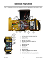
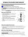
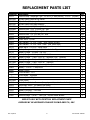
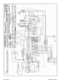
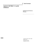
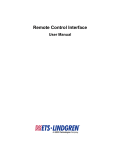
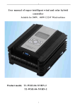
KEEP FOR FUTURE REFERENCE
SERVICE MANUAL
P.O. Box 368 – 908 West Main
Laurel, MT USA 59044
phone 800-548-7341
phone 406-628-8231
fax 406-628-8354
STOCK NUMBER 36100
2.5 SCFM NOMINAL AIRFLOW
DUAL VACUUM SYSTEM
DC-VOLTAGE POWER SYSTEM
READ ALL INSTRUCTIONS AND SAFETY RULES
BEFORE SERVICING THIS LIFTER
DESIGNED FOR THE TECHNICAL SERVICE PROFESSIONAL
TABLE OF CONTENTS
TABLE OF CONTENTS ...................................................................................................... 1
BEFORE SERVICING LIFTER ........................................................................................... 2
SERVICE SCHEDULE ................................................................................................................... 2
SERVICE FEATURES ........................................................................................................ 3
BATTERY CHARGER TEST ............................................................................................... 4
IN-LINE AIR FILTER SERVICE ........................................................................................ 5
FILTER FUNCTION AND CONDITIONS REQUIRING SERVICE ............................................................... 5
FILTER SERVICE PROCEDURE....................................................................................................... 5
DYNAFLO DV1034204 PUMP SERVICE ........................................................................... 6
CONDITIONS REQUIRING SERVICE ............................................................................................... 6
REPLACING A DIAPHRAGM .......................................................................................................... 6
REPLACING A GASKET/FLAP VALVES............................................................................................. 6
REPLACING A HEAD ASSEMBLY .................................................................................................... 6
DIGITAL VACUUM SWITCH ADJUSTMENT...................................................................... 7
VACUUM SWITCH FUNCTION ....................................................................................................... 7
ADJUSTMENT PROCEDURE ........................................................................................................... 7
REPLACEMENT PARTS LIST ............................................................................................ 9
LIMITED WARRANTY .................................................................................................... 11
Rev 0.7/9-15
1
2.5 DC DVS: #36100
BEFORE SERVICING LIFTER
Make sure battery is disconnected before servicing lifter.
Service personnel must read and understand the OPERATING INSTRUCTIONS before attempting
to service the vacuum lifter. Many of the following discussions assume knowledge of the
OPERATING INSTRUCTIONS or access to them.
Wiring and/or hose routing diagrams are provided in the final section of this SERVICE
MANUAL for reference when servicing the lifter or trouble-shooting a deficiency. If necessary,
consult the OPERATING INSTRUCTIONS to determine which diagrams are applicable to your
specific lifter model and any associated options.
Note:
SERVICE SCHEDULE
Service must be performed whenever a deficiency is indicated by routine inspections or tests.
Follow the Inspection Schedule and Testing Schedule as directed in the MAINTENANCE section of
the OPERATING INSTRUCTIONS. Any service warranted must be performed before resuming
normal operation of the lifter.
Rev 0.7/9-15
2
2.5 DC DVS: #36100
SERVICE FEATURES
Note: Components shown here are underlined on their first appearance in each section to follow.
1
10
2
7
9
8
7
6
5
4
3
14
13
12
11
Rev 0.7/9-15
1
OPTIONAL REMOTE CONTROL CONNECTOR
2
POWER SWITCH
3
BATTERY GAUGE
4
BATTERY TEST SWITCH
5
OPTIONAL STROBE LIGHT CONNECTOR
6
CHECK VALVE
7
VACUUM SWITCHES
8
VACUUM PUMP
9
AIR FILTER
10
CIRCUIT BREAKER
11
VACUUM GAUGES
12
POWER LOSS WARNING BATTERY HOLDER
13
VACUUM LIFT LIGHT
14
LOW VACUUM/POWER LOSS WARNING BUZZER
3
2.5 DC DVS: #36100
BATTERY CHARGER TEST
If you suspect the battery charger is not working correctly, this test
allows you to determine whether to replace it. Perform this test only
when the battery is not fully charged (see BATTERY TEST in MAINTENANCE
section of OPERATING INSTRUCTIONS). While the lifter's power switch
is in the OFF position (
) and the battery charger is disconnected from
any AC power source, use the battery test switch to take an energy
reading on the battery gauge. Then plug the charger in to an
appropriate AC power source and allow a few moments for the battery
gauge to show an accurate energy reading. If the charger is functioning
correctly, the energy reading should be higher when the charger is plugged in.
not functioning correctly, replace it according to the wiring diagram provided.
Rev 0.7/9-15
4
If the charger is
2.5 DC DVS: #36100
IN-LINE AIR FILTER SERVICE
FILTER FUNCTION AND CONDITIONS REQUIRING SERVICE
This air filter prevents solid particles from contaminating components in the vacuum system.
Caution: Examine air filter regularly and empty when necessary.
Open each filter regularly to determine whether liquid or other contaminants are trapped inside.
Remove any liquid or contaminants found. Clean or replace the filter element if it has an overall
dirty appearance, or if there is a noticeable increase in the time required to attain full vacuum
(see REPLACEMENT PARTS LIST).
FILTER SERVICE PROCEDURE
1) Hold the filter case (1) and turn the
removable end (2) counter-clockwise
approximately 45° until it stops
moving.
2) Pull the end outward from the case
and remove the filter element (3).
Use an air hose or other suitable
means to remove any liquid or other
contaminants found inside the case.
Also make sure the seal (4) is not
damaged.
3) Determine whether the filter element needs to be replaced (see CONDITIONS REQUIRING SERVICE
above).
4) Depending on the outcome of step 3, install a new element or reinstall the old element, as
shown in the illustration.
5) Align the 2 projections on the removable end with the grooves in the case, and insert the end
into the case. Push in and turn the end clockwise approximately 45° until it stops moving.
Make sure that the projections are completely visible through the windows (5) in the case.
6) Test the vacuum system, to make sure the air filter does not leak (see VACUUM TEST in
OPERATING INSTRUCTIONS).
Rev 0.7/9-15
5
2.5 DC DVS: #36100
DYNAFLO DV1034204 PUMP SERVICE
CONDITIONS REQUIRING SERVICE
Before performing any service, disconnect power source.
If the vacuum pump takes too long to attain full vacuum, it may require service. Replace the
diaphragms, gaskets/flap valves or (when preferable) the entire head assemblies1, as necessary to obtain
acceptable pump performance (see REPLACEMENT PARTS LIST). Perform the following service on both
heads of the pump.
Caution: Do not over-tighten the head screws, because this may damage the threads
in the pump body.
REPLACING A DIAPHRAGM
1) Remove the four head screws (1) and lock washers (2), and
remove the head assembly (3―7).
2) Remove the diaphragm retaining screw (8), diaphragm (9)
and rubber O-ring (10).
Note: Be sure to save the flat washer located between the
O-ring and the connecting rod (11). Also take note of the
diaphragm orientation for reassembly.
3) Replace the diaphragm, rubber O-ring and diaphragm
retaining screw. Reinstall the flat washer in its original
position.
4) Reverse the steps above for reassembly, as shown in the
illustration.
1
2
3
4
HEAD SCREW
LOCK WASHER
HEAD
INTAKE PORT (VACUUM)
5
6
7
8
GASKET/FLAP VALVES
9 DIAPHRAGM
VALVE PLATE
10 RUBBER O-RING
VALVE PLATE SCREW
11 CONNECTING ROD
DIAPHRAGM RETAINING SCREW 12 MOUNTING FOOT
13
14
15
16
WIRES
MOTOR
ALIGNMENT PIN
EXHAUST PORT (PRESSURE)
REPLACING A GASKET/FLAP VALVES
1) Remove the four head screws (1) and lock washers (2), and remove the head assembly (3―7).
2) Invert the head and remove the two valve plate screws (7). Remove the valve plate (6) to access the
gasket/flap valves.
3) Replace the gasket/flap valves (5) and reverse the steps above for reassembly, as shown in the
illustration. Use the alignment pin (15) to ensure proper fit between the head and valve plate.
REPLACING A HEAD ASSEMBLY
1) Remove the four head screws (1), lock washers (2) and head assembly (3―7).
2) Replace the head assembly, and reverse the steps above for reassembly, as shown in the illustration.
Caution: Depending on the product, the head assembly (3―7) may be rotated to an orientation different from the one
shown. When removing the head assembly, always take note of its orientation and install it the same way during reassembly.
1
Rev 0.7/9-15
6
2.5 DC DVS: #36100
DIGITAL VACUUM SWITCH ADJUSTMENT
VACUUM SWITCH FUNCTION
Two vacuum switches control various functions of the vacuum lifter (see SERVICE FEATURES for
location of vacuum switches). While the lifter is powered up, each vacuum switch senses the
vacuum level in one of the two vacuum circuits of the vacuum system. If either circuit loses
significant vacuum while the lifter is in the apply mode, the system responds automatically.
Each vacuum switch controls two functions: Settings n_1 and n_2 control the vacuum pump(s)
and the battery gauge. Settings n_3 and n_4 control a vacuum lift light and low vacuum
warning buzzer, light and/or strobe light.
Both vacuum switches should have the same settings to ensure the two circuits are functioning
together. Although the vacuum switches are set at the factory and should not require
adjustment, the following section lists the factory settings, in case adjustment is necessary.
ADJUSTMENT PROCEDURE
Lifting capacity decreases whenever vacuum switch is adjusted to maintain
lower vacuum level.
1) To unlock the vacuum switch settings, press and hold the “SET”
button for at least five seconds. Note that a different menu may
appear if the button is released too soon.2 Use the arrow keys to
access the unlocked mode (“UnL”) and press the “SET” button again.
2) Press and release the “SET” button to access the different vacuum
switch settings (n_1, n_2, n_3, n_4). Use the arrow keys to adjust
each setting and then press the “SET” button to continue to the next
setting. The following values should appear on the digital display:
• n_1 = -458. This setting turns off power to the vacuum pump(s)
when the vacuum system reaches the maximum vacuum level.
Setting n_1 must always be set above n_2.
Note: Lowering this value allows the pump(s) to shut off at higher elevations, but it also
requires the pump(s) to run more frequently.
2
The vacuum switch has additional settings that should not be adjusted. These settings are accessed if the “SET” button is
held for 3 seconds. For reference, the correct settings are provided below.
•
Setting 1 should display “nnH”
•
Setting 2 should display “1nC”
•
Setting 3 should display “2nC”
•
Setting 4 should display “192”
•
Setting 5 should display “nAn”
Rev 0.7/9-15
7
2.5 DC DVS: #36100
• n_2 = -425. After a vacuum switch has turned off the vacuum pump(s) (see n_1) and the
vacuum system begins to lose vacuum, setting n_2 turns on power again to the vacuum
pump(s). The vacuum pump(s) should turn on before the needle on either vacuum gauge
moves from the green range to the red range. Setting n_2 must always be set above n_4.
• n_3 = -422. This setting turns off the low vacuum warning buzzer, light and/or strobe light
and turns on the vacuum lift light, indicating that the lifter has already reached the
minimum vacuum level (see n_4). Setting n_3 must always be set above n_4.
• n_4 = -419. After the vacuum switch has turned off the vacuum pump(s) (see n_1) and
the vacuum system has lost significant vacuum, setting n_4 turns on the low vacuum
warning buzzer, light and/or strobe light and turns off the vacuum lift light. This signals a
loss of adequate vacuum to the lifter operator.
This
setting must not be lowered without first consulting Wood’s Powr-Grip, because
it may reduce the maximum lifting capacity.
Note: Setting n_4 corresponds with the minimum vacuum level for lifting loads.
3) Each vacuum switch must be locked after all adjustments have been made. Use the arrow
keys to access the locked mode (“LoC”) and press the “SET” button again.
4) Repeat steps 1-4 for the other vacuum switch, to ensure the settings are the same.
Rev 0.7/9-15
8
2.5 DC DVS: #36100
REPLACEMENT PARTS LIST
Stock No.
Description
93221
Vacuum Pump - Diaphragm Type - 2.5-SCFM [71 liters/minute] - 12 V DC (Dynaflo)
1
66197BM
Dynaflo Pump Gasket & Flap Valves
2
66197AM
Dynaflo Pump Diaphragm Kit
2
66197AA
Dynaflo Pump Dual-Head Assembly
2
65442CA
Vacuum Hose - 1/4" [6.3 mm] OD - Red
A/R
65439AM
Vacuum Hose - 5/32" [4.0 mm] OD - Red
A/R
65439
Vacuum Hose - 5/32" [4.0 mm] OD - Blue
A/R
65429
Vacuum Hose - 1/4" [6.3 mm] OD - Blue
A/R
65254
Solenoid valve
2
65211
Check Valve - 1/8 NPT
2
64834
LED Indicator - 12 V DC - Green (aka, vacuum lift light)
1
64832
LED Indicator - 12 V DC - Blue - Small (aka, power light)
1
64752
Audio Alarm - 5-15 V DC - Panel Mount
1
64716
Battery Charger - 0.8 Amp - 240 V AC - Australian Type
1
64715
Battery Charger - 0.8 Amp - 240 V AC
1
64714
Battery Charger - 0.8 Amp - 100 / 120 V AC
1
64713AM
Battery Charger - 7 Amp - 240 V AC - Australian Type (optional)
1
64712AM
Battery Charger - 7 Amp - 100 / 120 V AC (optional)
1
64711AM
Battery Charger - 7 Amp - 240 V AC (optional)
1
64665
Battery - 12 V DC - 18 Amp-Hours (optional)
1
64664
Battery - 12 V DC - 7 Amp-Hours
1
64590
Battery Gauge
1
64460
Circuit Breaker - 15 A
1
Circuit Board - Populated
1
64238AA
Vacuum Switch - Digital
2
64234AM
Power Switch
1
64213
Push-Button Switch - Chrome (for apply, enable, and release buttons)
3
64209
Momentary Switch (for battery test switch)
1
59086
Battery Connector - Twin Lead - Comfort Connect
1
54392
Battery Connector - Twin Lead
1
16131
Element for Air Filter
2
15920
Vacuum Gauge - 1/8 NPT - CBM Type - w/Panel Mount Bracket
2
―
Qty.
SERVICE ONLY WITH IDENTICAL REPLACEMENT PARTS
SUPPLIED BY OR APPROVED BY WOOD'S POWR-GRIP CO., INC.
Rev 0.7/9-15
9
2.5 DC DVS: #36100
LIMITED WARRANTY
Powr-Grip products are carefully constructed, thoroughly inspected at various stages of
production, and individually tested. They are warranted to be free from defects in workmanship
and materials for a period of one year from the date of purchase.
If a problem develops during the warranty period, follow the instructions hereafter to obtain
warranty service. If inspection shows that the problem is due to defective workmanship or
materials, Powr-Grip will repair the product without charge.
WARRANTY DOES NOT APPLY WHEN:
Modifications have been made to the product after leaving the factory.
Rubber portions have been cut or scratched during use.
Repairs are required due to abnormal wear and tear.
The product has been damaged, misused, or neglected.
If a problem is not covered under warranty, Powr-Grip will notify the customer of costs prior to
repair. If the customer agrees to pay all repair costs and to receive the repaired product on a
C.O.D. basis, Powr-Grip then will proceed with repairs.
TO OBTAIN REPAIRS OR WARRANTY SERVICE
For purchases in North America:
Contact the Technical Service Department at Wood’s Powr-Grip Co. When factory service
is required, ship the complete product–prepaid–along with your name, address and phone
number to the street address hereafter.
For purchases in all other localities:
Contact your dealer or the Technical Service Department at Wood’s Powr-Grip Co. for
assistance.
Wood's Powr-Grip Co., Inc.
908 West Main St. / P.O. Box 368
Laurel, MT USA 59044
phone 800-548-7341
phone 406-628-8231
fax 406-628-8354
Rev 0.7/9-15
10
2.5 DC DVS: #36100
Rev 0.7/9-15
11
2.5 DC DVS: #36100
Rev 0.7/9-15
12
2.5 DC DVS: #36100
Rev 0.7/9-15
13
2.5 DC DVS: #36100
Rev 0.7/9-15
14
2.5 DC DVS: #36100
Rev 0.7/9-15
15
2.5 DC DVS: #36100
Rev 0.7/9-15
16
2.5 DC DVS: #36100