1
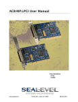
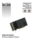
ACB-MP+4.PCI User Manual
Part Number 5402
www.sealevel.com
PO Box 830 – Liberty, SC 29657
864.843.4343
Table of Contents
INTRODUCTION......................................................................................................................... 1 OTHER SEALEVEL SYNC PRODUCTS ............................................................................................. 1 BEFORE YOU GET STARTED ................................................................................................. 2 WHAT’S INCLUDED ...................................................................................................................... 2 OPTIONAL ITEMS.......................................................................................................................... 2 INSTALLATION & CONFIGURATION.................................................................................. 3 SOFTWARE INSTALLATION ........................................................................................................... 3 PHYSICAL INSTALLATION ............................................................................................................ 4 TECHNICAL DESCRIPTION.................................................................................................... 5 INTERNAL BAUD RATE GENERATOR ............................................................................................ 5 CONTROL AND STATUS REGISTERS DEFINITION........................................................................... 5 100-PIN CONNECTOR PIN OUT ..................................................................................................... 6 INTERFACE SELECTION ................................................................................................................ 7 DB-25M CONNECTOR PIN OUTS ................................................................................................. 7 ELECTRICAL CHARACTERISTICS .................................................................................... 10 FEATURES .................................................................................................................................. 10 SPECIFICATIONS ......................................................................................................................... 10 APPENDIX A – TROUBLESHOOTING................................................................................. 11 APPENDIX B - HOW TO GET ASSISTANCE ...................................................................... 12 APPENDIX C – ELECTRICAL INTERFACE ....................................................................... 13 APPENDIX D – SILK SCREEN – 5402 PCB .......................................................................... 15 APPENDIX E - COMPLIANCE NOTICES ............................................................................ 16 FEDERAL COMMUNICATIONS COMMISSION STATEMENT ........................................................... 16 WARRANTY............................................................................................................................... 17 © Sealevel Systems, Inc.
SL9047 Revision 7/2009
ACB-MP+4.PCI User Manual
Introduction
The ACB-MP+4.PCI (Item# 5402) is a four-port PCI bus RS-232, RS-422, RS-485
synchronous serial interface. Designed using the popular Zilog Z85230 Enhanced
Serial Communication Controller (ESCC), the board is an ideal solution for military,
satellite, radar, banking, and other applications that require robust synchronous
communications.
For maximum flexibility, each of the serial ports can be individually configured for
RS-232, RS-422, or RS-485 communications. In RS-232 mode, all common modem
control signals are implemented for compatibility with a wide range of peripherals.
A digital phase lock loop (DPLL) is included on each port, and the board supports
data rates up to 128K bps in burst mode. For easy implementation, a fan-out cable is
included that terminates the onboard 100-pin connector to four DB-25M connectors.
The ACB-MP+4.PCI features Universal Bus (3.3V and 5V) compatibility with both
new and legacy computer systems. Software support, critical for successful
synchronous communication development, is provided through Sealevel’s SeaMAC
V4 driver. HDLC/SDLC protocols are supported as well as certain configurations of
Monosync, Bi-sync, and Raw modes.
The ACB-MP+4.PCI also utilizes the Sipex-505 multi-protocol electrical interface
chip that allows the ACB-MP+4.PCI to be compliant with EIA/TIA-530/530A,
EIA/TIA-232E, EIA/TIA-485, and ITU V.35. Optional cables are available to
connect RS-449, RS-530, RS-530A, V.35 and X.21 interfaces.
Other Sealevel Sync Products
PCI – 1-Port
Route 56.PCI
(P/N 5101)
- Z16C32 RS-232/422/485/530/530a/V.35
ACB-MP.PCI
(P/N 5102)
- Z85230 RS-232/422/485/530/530a/V.35
Low Profile PCI – 1-Port
ACB-232.LPCI
(P/N 5103)
- Z85230 RS-232
ACB-Ultra.LPCI
(P/N 5104)
- Z16C32 RS-232/422/485/530/530a/V.35
PC/104 – 1-Port
ACB-104
(P/N 3512)
- Z85230 RS-232/422/485/530/530a/V.35
ACB-104.ULTRA (P/N 3514)
- Z16C32 RS-232/422/485/530/530a/V.35
PCMCIA – 1-Port
PC-ACB-MP
(P/N 3612)
- Z85233 RS-232/422/485/530/530a/V.35
© Sealevel Systems, Inc.
-1-
ACB-MP+4.PCI User Manual
Before You Get Started
What’s Included
The ACB-MP+4.PCI is shipped with the following items. If any of these items is
missing or damaged please contact Sealevel for replacement.
Item# 5402 – ACB-MP+4.PCI Adapter
Item# CA339 – 100-Pin to (4) DB25M Breakout Cable, 36” in Length
Item# SSI-CD – Sealevel Software CD with SeaMAC drivers
Optional Items
Depending upon your application, you are likely to find one or more of the following
items useful for interfacing the ACB-MP+4.PCI to real-world signals. All items can
be purchased from our website (http://www.sealevel.com) or by calling 864-8434343.
CA104 – A 6’ serial extension cable with one DB-25 female connector and one
DB-25 male connector, pinned one-to-one.
CA107 – a 10” shielded cabling adapter with a DB-25F (RS-530) to a DB-37M
(RS-449 DTE). RS-530 is replacing RS-449 in Telecom applications, but there is
still a very large installed base of equipment that still uses the RS-449 pin-out.
Both standards use RS-422 to define the electrical specifications and are
interchangeable via this adapter cable.
CA159 – A 6’ shielded cable with a DB-25 female connector (RS-530 pin out) to
a DB-15 male connector (X.21 pin out) that converts the standard DB-25
implementation of RS-530 or RS-422 to the ITU-T X.21 standard.
CA174 – A 6’ serial extension cable with twisted data pairs for increased data
integrity. Recommended for high-speed RS-530 connections.
CA178 – A 6’ shielded cable with a DB-25 female connector to an ITU-T ISO2593 style connector (V.35) that converts the Sealevel DB-25 implementation to
the ITU-T V.35 mechanical standard.
© Sealevel Systems, Inc.
-2-
ACB-MP+4.PCI User Manual
Installation & Configuration
Software Installation
Windows 2000/XP/Vista™ Operating Systems
Do not install the adapter until the software has been
successfully installed..
Note: SeaMAC V4 is only supported under 32-bit versions of Windows 2000,
XP, and Vista operating systems.
1. Start Windows.
2. Insert the Sealevel Systems CD in your CD drive.
3. If ‘Auto-Start’ is enabled for this drive the software will automatically launch.
Otherwise launch the ‘autorun.exe’ file located in the root directory of the CD.
4. Click the ‘Install’ button.
5. Type in or select the part number for the adapter from the listing.
6. The setup files will automatically detect the operating environment and install the
proper components. Follow the information presented on the screens that follow.
7. IN Windows XP, a screen may appear with the declaration: “The publisher
cannot be determined due to the problems below: Authenticode signature not
found.” Please click the ‘Yes’ button and proceed with the installation. This
declaration simply means that the operating system is not aware of the driver
being loaded. It will not cause any harm to your system.
8. During setup, the user may specify installation directories and other preferred
configurations. This program also adds entries to the system registry that are
necessary for specifying the operating parameters for each driver. An uninstall
option is also included to remove all registry/INI file entries from the system.
9. The software is now installed and you can proceed with the hardware
installation.
© Sealevel Systems, Inc.
-3-
ACB-MP+4.PCI User Manual
Physical Installation
The adapter is universal bus compatible and can be installed in any 3.3V or 5V PCI
expansion slot.
Do not install the adapter until the software has been
successfully installed..
1. Turn off power. Disconnect the power cord.
2. Remove the PC case cover.
3. Locate an available PCI slot and remove the blank metal slot cover.
4. Gently insert the PCI adapter into the slot. Make sure the adapter is seated
properly.
5. Replace the screw (required for FCC Part 15 compliance).
6. Replace the cover.
7. Connect the power cord and power up the machine.
The ACB-MP+4.PCI is now ready for use.
© Sealevel Systems, Inc.
-4-
ACB-MP+4.PCI User Manual
Technical Description
The ACB-MP+4.PCI utilizes the Zilog 85230 Enhanced Serial Communications
Controller (ESCC) and includes a dedicated Z85230 per port. This chip features
programmable baud rate, data format and interrupt control. Refer to the ESCC Users
Manual, available from Zilog, for details on programming the 85230 ESCC chip.
Internal Baud Rate Generator
The baud rate of the ESCC is programmed under software control. The standard
oscillator supplied with the board is 7.3728 MHz. However, other oscillator values
can be substituted to achieve different baud rates.
Control and Status Registers Definition
The control and status registers occupy 12 consecutive I/O locations. The following
tables provide a functional description of the bit positions. X = do not care.
Base
+4
+5
+5
+6
+6
+7
+14
+15
Mode
RD
RD
WR
RD
WR
RD
RD
RD
D7
0
485CLK
485CLK
0
X
X
SD7
SD15
D6
IRQST
ECHOA
ECHOA
0
X
X
SD6
SD14
D5
0
SYNCA_RTS
SYNCA_RTS
0
X
X
SD5
SD13
D4
0
SYNCA_CTS
SYNCA_CTS
0
X
X
SD4
SD12
D3
0
AM3
AM3
RLA
RLA
IRQST4
SD3
SD11
D2
0
AM2
AM2
LLA
LLA
IRQST3
SD2
SD10
Field
IRQST
DSRA
LLA
RLA
TSETSLA
RXCOPTA
SCC interrupt status:
DSRA:
Local Loopback:
Remote Loopback:
TSET clock source:
RXCOPTA:
Description
1 = No interrupt pending on ESCC
1 = DSRA not active
1 = LL set
1 = RL set
1= Received TXC as source
1= Selects SCC PCLK for RTXCA
SYNCA_RTS
SYNCA_CTS
485CLK
ECHOA
AM0 – AM3
SD0 – SD15
SYNCA _RTS:
1 = SYNCA connected to RTS
SYNCA_CTS:
1 = SYNCA connected to CTS
TSET switches with TXD: 1 = clk switches
ECHO enable:
1 = echo disabled
I/O mode select. See table for valid interface options.
Optional security feature. Unique value per customer or application.
D1
0
AM1
AM1
TSETSLA
TSETSLA
IRQST2
SD1
SD9
D0
DSRA
AM0
AM0
RXCOPTA
RXCOPTA
IRQST1
SD0
SD8
0 = Interrupt pending on ESCC.
0 = DSRA active
0 = LL not set
0 = RL not set
0 = TRXCA as source
0 = Selects received RXC for
RTXCA
0 = SYNCA is high
0 = SYNCA is high
0 = no CLK switching
0 = echo enabled
0 = High Impedance
Default value = FFFF
Note: Default values are listed in bold
© Sealevel Systems, Inc.
-5-
ACB-MP+4.PCI User Manual
100-Pin Connector Pin Out
The ACB-MP+4.PCI has a 100-pin high-density connector and includes a cable
(Item# CA339) that breaks out to four (4) DB25 male connectors. The pin outs for
RS-232, RS-485, RS-530, RS-530A, and V.35 interfaces on the DB25 connectors
are listed on the following pages. For customers designing their own cable, the
mating 100-pin connector is AMP p/n 5787169-9. The pin out for the 100-pin
connector is listed below.
100-Pin Connector
Signal Name
DB25
Port 1
1
51
26
76
GND
7
2
52
27
77
TXD-
2
3
53
28
78
TXD+
14
4
54
29
79
RTS-
4
5
55
30
80
RTS+
19
6
56
31
81
DTR-
20
7
57
32
82
N/C
Port 2
Port 3
Port 4
DTR+
23
8
58
33
83
TSET-
24
9
59
34
84
TSET+
11
10
60
35
85
RXD-
3
11
61
36
86
RXD+
16
12
62
37
87
CTS-
5
13
63
38
88
CTS+
13
14
64
39
89
DSR-
6
15
65
40
90
DSR+
22
16
66
41
91
DCD-
8
17
67
42
92
DCD+
10
18
68
43
93
TXC-
15
19
69
44
94
TXC+
12
20
70
45
95
RXC-
17
21
71
46
96
RXC+
9
22
72
47
97
LL-
18
23
73
48
98
RL-
21
24
74
49
99
25
75
50
100
Shell
Shell
Shell
Shell
NC
SHIELD
© Sealevel Systems, Inc.
Shell
-6-
ACB-MP+4.PCI User Manual
Interface Selection
The ACB-MP+4.PCI supports a variety of electrical interfaces. Refer to the Control
and Status Register Definitions found in the Technical Description section of this
manual for this bit description. There is line termination on RXD, RXC, and TXC in
the following modes: RS-530, RS-530A, RS-485T, and V.35.
HEX
0
1
2
3
4
5
6,7,8,9
A
B
C
D
E
F
M3
0
0
0
0
0
0
0
1
1
1
1
1
1
M2
0
0
0
0
1
1
1
0
0
1
1
1
1
M1
0
0
1
1
0
0
1
1
1
0
0
1
1
M0
0
1
0
1
0
1
0
0
1
0
1
0
1
Interface Mode
All signals are high impedance
* not supported *
RS-232
* not supported *
RS-485T with 120Ω termination
RS-485 without termination
* not supported *
single ended loopback
differential loopback
* not supported *
RS-530
V.35
RS-530A
DB-25M Connector Pin Outs
RS-232 Signals
Base+5, M3-M0=2, 0010
Pin #
2
3
4
5
6
7
8
15
17
18
20
21
24
© Sealevel Systems, Inc.
Signal
TD
RD
RTS
CTS
DSR
GND
DCD
TXC
RXC
LL
DTR
RL
TSET
Name
Transmit Data
Receive Data
Request To Send
Clear To Send
Data Set Ready
Ground
Data Carrier Detect
Transmit Clock
Receive Clock
Local Loopback
Data Terminal Ready
Remote Loopback
Transmit Signal Element Timing
-7-
Mode
Output
Input
Output
Input
Input
Input
Input
Input
Output
Output
Output
Output
ACB-MP+4.PCI User Manual
RS-485 or RS-485T
Base+5, M3-M0=4, 0100 (With termination)
Base+5, M3-M0=5, 0101 (Without termination)
Pin #
2
3
7
9
11
12
14
15
16
17
24
Signal
TDA TX–
RDA RX–
GND
RXCB RXC+
TSETB TSET+
TXCB TXC+
TDB TX+
TXCA TXC–
RDB RX+
RXCA RXC–
TSETA TSET–
Name
Transmit Negative
Receive Negative
Ground
Receive Clock Positive
Transmit Signal Element Timing +
Transmit Clock Positive
Transmit Positive
Transmit Clock Negative
Receive Positive
Receive Clock Negative
Transmit Signal Element Timing –
Mode
Output
Input
Input
Output
Input
Output
Input
Input
Input
Output
RS-530 (RS-422)
Base+5, M3-M0=D, 1101
Pin #
2
3
4
5
6
7
8
9
10
11
12
13
14
15
16
17
18
19
20
21
22
23
24
Signal
TDA TX–
RDA RX–
RTSA RTS–
CTSA CTS–
DSRA DSR–
GND
DCDA DCD–
RXCB RXC+
DCDB DCD+
TSETB TSET+
TXCB TXC+
CTSB CTS+
TDB TX+
TXCA TXC–
RDB RX+
RXCA RXC–
LL
RTSB RTS+
DTRA DTR–
RL
DSRB DSR+
DTRB DTR+
TSETA TSET–
© Sealevel Systems, Inc.
Name
Transmit Negative
Receive Negative
Request To Send Negative
Clear To Send Negative
Data Set Ready Negative
Ground
Data Carrier Detect Negative
Receive Clock Positive
Data Carrier Detect Positive
Transmit Signal Element Timing +
Transmit Clock Positive
Clear To Send Positive
Transmit Positive
Transmit Clock Negative
Receive Positive
Receive Clock Negative
Local Loopback
Request To Send Positive
Data Terminal Ready Negative
Remote Loopback
Data Set Ready Positive
Data Terminal Ready Positive
Transmit Signal Element Timing –
-8-
Mode
Output
Input
Output
Input
Input
Input
Input
Input
Output
Input
Input
Output
Input
Input
Input
Output
Output
Output
Output
Input
Output
Output
ACB-MP+4.PCI User Manual
RS-530A
Base+5, M3-M0=F, 1111
Pin #
2
3
4
5
6
7
8
9
11
12
13
14
15
16
17
18
19
20
21
24
Signal
TDA TX–
RDA RX–
RTSA RTS–
CTSA CTS–
DSRA DSR–
GND
DCDA DCD–
RXCB RXC+
TSETB TSET+
TXCB TXC+
CTSB CTS+
TDB TX+
TXCA TXC–
RDB RX+
RXCA RXC–
LL
RTSB RTS+
DTRA DTR–
RL
TSETA TSET–
Name
Transmit Negative
Receive Negative
Request To Send Negative
Clear To Send Negative
Data Set Ready Negative
Ground
Data Carrier Detect Negative
Receive Clock Positive
Transmit Signal Element Timing +
Transmit Clock Positive
Clear To Send Positive
Transmit Positive
Transmit Clock Negative
Receive Positive
Receive Clock Negative
Local Loopback
Request To Send Positive
Data Terminal Ready Negative
Remote Loopback
Transmit Signal Element Timing –
Mode
Output
Input
Output
Input
Input
Input
Input
Output
Input
Input
Output
Input
Input
Input
Output
Output
Output
Output
Output
V.35 Signals
Base+5, M3-M0=E, 1110
Pin #
Signal
Name
V.35
Mode
2
TDA TX–
Transmit Negative
P
Output
3
RDA RX–
Receive Negative
R
Input
4
RTS
Request To Send
C
Output *
5
CTS
Clear To Send
D
Input *
6
DSR
Data Set Ready
E
Input *
7
GND
Ground
B
8
DCD
Data Carrier Detect
F
Input *
9
RXCB RXC+
Receive Clock Positive
X
Input
11
TSETB TSET+
Transmit Signal Element Timing +
W
Output
12
TXCB TXC+
Transmit Clock Positive
AA
Input
14
TDB TX+
Transmit Positive
S
Output
15
TXCA TXC–
Transmit Clock Negative
Y
Input
16
RDB RX+
Receive Positive
T
Input
17
RXCA RXC–
Receive Clock Negative
V
Input
18
LL
Local Loopback
Output *
20
DTR
Data Terminal Ready
H
Output *
21
RL
Remote Loopback
Output *
24
TSETA TSET–
Transmit Signal Element Timing –
U
Output
Note: All modem control signals are single ended (un-balanced) with RS-232 signal levels.
© Sealevel Systems, Inc.
-9-
ACB-MP+4.PCI User Manual
Electrical Characteristics
Features
Configurable for RS-232, RS-422, RS-485, RS-530, RS-530A, or V.35
Z85230 Enhanced Serial Communications Controller (ESCC™) supporting
synchronous or asynchronous communications
Programmable electrical interface selection for EIA/TIA-232/530/530A/485 and
ITU V.35
Programmable options for Transmit clock as input or output
Software programmable baud rates
Data rates to 128K bps
Included cable with (4) DB25M connectors
X.21 and RS-449 serial interface capability with versatile cabling options
Specifications
Environmental Specifications
Specification
Temperature
Range
Humidity Range
Operating
0º to 70º C
(32º to 158º F)
10 to 90% R.H.
Non-Condensing
Storage
-50º to 105º C
(-58º to 221º F)
10 to 90% R.H.
Non-Condensing
Power Requirements
+5VDC @ 750mA
Dimensions
L
6.53”
16.58cm
W
4.20”
10.69cm
Manufacturing
All Sealevel Systems Printed Circuit boards are built to UL 94V0 rating and are
100% electrically tested. These printed circuit boards are solder mask over bare
copper with either Electroless Nickel Immersion Gold (ENIG) or Hot Air Solder
Leveled (HASL) finish.
© Sealevel Systems, Inc.
- 10 -
ACB-MP+4.PCI User Manual
Appendix A – Troubleshooting
Following these simple steps can eliminate most common problems.
1. Read this manual thoroughly before attempting to install the adapter in your
system.
2. Install software first. This places the required installation files in the correct
locations. After installing the software, proceed to the physical installation
section of this manual.
3. Identify all I/O adapters currently installed in your system. This includes
your on-board serial ports, controller cards, sound cards, etc. The I/O
addresses used by these adapters, as well as the IRQ (if any) should be
identified.
4. Configure your Sealevel Systems adapter so that there is no conflict with
currently installed adapters. No two adapters can occupy the same I/O
address.
5. Try the Sealevel Systems adapter with a unique IRQ. While the Sealevel
Systems adapter does allow the sharing of IRQs, many other adapters (i.e.,
SCSI adapters and on-board serial ports) do not.
6. Make sure the Sealevel Systems adapter is securely installed.
7. For Windows 2000/XP, the diagnostic tool ‘WinSSD’ is installed the
SeaMAC folder on the Start Menu during the setup process. First find the
ports using the Device Manager, then use ‘WinSSD’ to verify that the ports
are functional.
8. Always use Sealevel Systems diagnostic software when troubleshooting a
problem. This will eliminate any software issues from the equation.
If these steps do not solve your problem, please call Sealevel Systems’ Technical
Support, (864) 843-4343. Our technical support is free and available from 8:00AM5PM Eastern Time, Monday through Friday. For email support contact:
mailto:[email protected].
© Sealevel Systems, Inc.
- 11 -
ACB-MP+4.PCI User Manual
Appendix B - How To Get Assistance
Begin by reading through the Trouble Shooting Guide in Appendix A. If assistance
is still needed please see below.
When calling for technical assistance, please have your user manual and current
adapter settings. If possible, please have the adapter installed in a computer ready to
run diagnostics.
Sealevel Systems provides an FAQ section on its web site. Please refer to this to
answer many common questions. This section can be found at
http://www.sealevel.com/faq.asp
Sealevel Systems maintains a Home page on the Internet. Our home page address is
http://www.sealevel.com. The latest software updates, and newest manuals are
available via our FTP site that can be accessed from our home page.
Technical support is available Monday to Friday from 8:00 a.m. to 5:00 p.m. eastern
time. Technical support can be reached at (864) 843-4343.
RETURN AUTHORIZATION MUST BE OBTAINED FROM SEALEVEL
SYSTEMS BEFORE RETURNED MERCHANDISE WILL BE ACCEPTED.
AUTHORIZATION CAN BE OBTAINED BY CALLING SEALEVEL
SYSTEMS AND REQUESTING A RETURN MERCHANDISE
AUTHORIZATION (RMA) NUMBER.
© Sealevel Systems, Inc.
- 12 -
ACB-MP+4.PCI User Manual
Appendix C – Electrical Interface
RS-232
Quite possibly the most widely used communication standard is RS-232. This
implementation has been defined and revised several times and is often referred to as
RS-232 or EIA/TIA-232. It is defined by the EIA as the Interface between Data
Terminal Equipment and Data Circuit- Terminating Equipment Employing Serial
Binary Data Interchange. The mechanical implementation of RS-232 is on a 25 pin
D sub connector. RS-232 is capable of operating at data rates up to 20 Kbps at
distances less than 50 ft. The absolute maximum data rate may vary due to line
conditions and cable lengths. RS-232 often operates at 38.4 Kbps over very short
distances. The voltage levels defined by RS-232 range from -12 to +12 volts.
RS-232 is a single ended or unbalanced interface, meaning that a single electrical
signal is compared to a common signal (ground) to determine binary logic states. A
voltage of +12 volts (usually +3 to +10 volts) represents a binary 0 (space) and -12
volts (-3 to -10 volts) denotes a binary 1 (mark). The RS-232 and the EIA/TIA-574
specification defines two type of interface circuits, Data Terminal Equipment (DTE)
and Data Circuit-Terminating Equipment (DCE). The Sealevel Systems adapter is a
DTE interface.
RS-422
The RS-422 specification defines the electrical characteristics of balanced voltage
digital interface circuits. RS-422 is a differential interface that defines voltage levels
and driver/receiver electrical specifications. On a differential interface, logic levels
are defined by the difference in voltage between a pair of outputs or inputs. In
contrast, a single ended interface, for example RS-232, defines the logic levels as the
difference in voltage between a single signal and a common ground connection.
Differential interfaces are typically more immune to noise or voltage spikes that may
occur on the communication lines. Differential interfaces also have greater drive
capabilities that allow for longer cable lengths. RS-422 is rated up to 10 Megabits
per second and can have cabling 4000 feet long. RS-422 also defines driver and
receiver electrical characteristics that will allow 1 driver and up to 32 receivers on
the line at once. RS-422 signal levels range from 0 to +5 volts. RS-422 does not
define a physical connector.
© Sealevel Systems, Inc.
- 13 -
ACB-MP+4.PCI User Manual
RS-485
RS-485 is backwardly compatible with RS-422; however, it is optimized for
partyline or multi-drop applications. The output of the RS-422/485 driver is capable
of being Active (enabled) or Tri-State (disabled). This capability allows multiple
ports to be connected in a multi-drop bus and selectively polled. RS-485 allows
cable lengths up to 4000 feet and data rates up to 10 Megabits per second. The signal
levels for RS-485 are the same as those defined by RS-422. RS-485 has electrical
characteristics that allow for 32 drivers and 32 receivers to be connected to one line.
This interface is ideal for multi-drop or network environments. RS-485 tri-state
driver (not dual-state) will allow the electrical presence of the driver to be removed
from the line. Only one driver may be active at a time and the other driver(s) must
be tri-stated. RS-485 can be cabled in two ways, two wire and four wire mode. Two
wire mode does not allow for full duplex communication, and requires that data be
transferred in only one direction at a time. For half-duplex operation, the two
transmit pins should be connected to the two receive pins (Tx+ to Rx+ and Tx- to
Rx-). Four wire mode allows full duplex data transfers. RS-485 does not define a
connector pin-out or a set of modem control signals. RS-485 does not define a
physical connector.
RS-530 / 530A
RS-530 (a.k.a. EIA-530) compatibility means that RS-422 signal levels are met, and
the pin-out for the DB-25 connector is specified. The EIA (Electronic Industry
Association) created the RS-530 specification to detail the pin-out, and define a full
set of modem control signals that can be used for regulating flow control and line
status. The major difference between RS-530 and RS-530A lies in some of the
modem control interface signals. In RS-530 the signals all of the modem control
signals are differential, in RS-530A some of these signals are single ended. The
RS-530 specification defines two types of interface circuits, Data Terminal
Equipment (DTE) and Data Circuit-Terminating Equipment (DCE). The Sealevel
Systems adapter is a DTE interface.
V.35
V.35 is a standard defined by ITU (formerly CCITT) that specifies an electrical,
mechanical, and physical interface that is used extensively by high-speed digital
carriers such as AT&T Dataphone Digital Service (DDS). ITU V.35 is an
international standard that is often refereed to as Data Transmission at 48 Kbps
Using 60 - 108 KHz Group-Band Circuits. ITU V.35 electrical characteristics are a
combination of unbalanced voltage and balanced current mode signals. Data and
clock signals are balanced current mode circuits. These circuits typically have
voltage levels from 0.5 Volts to -0.5 Volts (1 Volt differential). The modem control
signals are unbalanced signals and are compatible with RS-232. The physical
connector is a 34 pin connector that supports 24 data, clock and control signals. The
physical connector is defined in the ISO-2593 standard. ITU V.35 specification
defines two type of interface circuits, Data Terminal Equipment (DTE) and Data
Circuit-Terminating Equipment (DCE). The Sealevel Systems adapter is a DTE
interface.
© Sealevel Systems, Inc.
- 14 -
ACB-MP+4.PCI User Manual
Appendix D – Silk Screen – 5402 PCB
© Sealevel Systems, Inc.
- 15 -
ACB-MP+4.PCI User Manual
Appendix E - Compliance Notices
Federal Communications Commission Statement
FCC - This equipment has been tested and found to comply with the limits for Class
A digital device, pursuant to Part 15 of the FCC Rules. These limits are designed to
provide reasonable protection against harmful interference when the equipment is
operated in a commercial environment. This equipment generates, uses, and can
radiate radio frequency energy and, if not installed and used in accordance with the
instruction manual, may cause harmful interference to radio communications.
Operation of this equipment in a residential area is likely to cause harmful
interference in such case the user will be required to correct the interference at the
users expense.
EMC Directive Statement
Products bearing the CE Label fulfill the requirements of the EMC directive
(89/336/EEC) and of the low-voltage directive (73/23/EEC) issued by the European
Commission.
To obey these directives, the following European standards must be met:
EN55022 Class A - “Limits and methods of measurement of radio interference
characteristics of information technology equipment”
EN55024 – “Information technology equipment Immunity characteristics Limits and
methods of measurement”.
EN60950 (IEC950) - “Safety of information technology equipment, including
electrical business equipment”
Warning
This is a Class A Product. In a domestic environment, this product may cause
radio interference in which case the user may be required to take adequate
measures to prevent or correct the interference.
Always use cabling provided with this product if possible. If no cable is provided or
if an alternate cable is required, use high quality shielded cabling to maintain
compliance with FCC/EMC directives.
© Sealevel Systems, Inc.
- 16 -
ACB-MP+4.PCI User Manual
Warranty
Sealevel's commitment to providing the best I/O solutions is reflected in the
Lifetime Warranty that is standard on all Sealevel manufactured products. We are
able to offer this warranty due to our control of manufacturing quality and the
historically high reliability of our products in the field. Sealevel products are
designed and manufactured at its Liberty, South Carolina facility, allowing direct
control over product development, production, burn-in and testing.
Sealevel Systems, Inc. (hereafter "Sealevel") warrants that the Product shall conform
to and perform in accordance with published technical specifications and shall be
free of defects in materials and workmanship for life. In the event of failure,
Sealevel will repair or replace the product at Sealevel's sole discretion. Failures
resulting from misapplication or misuse of the Product, failure to adhere to any
specifications or instructions, or failure resulting from neglect or abuse are not
covered under this warranty.
Warranty service is obtained by delivering the Product to Sealevel and providing
proof of purchase. Return authorization must be obtained from Sealevel Systems
before returned merchandise will be accepted. Authorization is obtained by
calling Sealevel Systems and requesting a Return Merchandise Authorization
(RMA) number. The Customer agrees to insure the Product or assume the risk of
loss or damage in transit, to prepay shipping charges to Sealevel, and to use the
original shipping container or equivalent. Warranty is valid only for original
purchaser and is not transferable.
Sealevel Systems assumes no liability for any damages, lost profits, lost savings or
any other incidental or consequential damage resulting from the use, misuse of, or
inability to use this product. Sealevel Systems will not be liable for any claim made
by any other related party.
This warranty applies to Sealevel manufactured Product. Product purchased through
Sealevel but manufactured by a third party will retain the original manufacturer's
warranty.
Sealevel Systems, Incorporated
PO Box 830
2779 Greenville Highway
Liberty, SC 29657 USA
(864) 843-4343
FAX: (864) 843-3067
www.sealevel.com
email: [email protected]
Technical Support is available Monday - Friday from 8 a.m. to 5 p.m. Eastern time.
Trademarks
Sealevel Systems, Incorporated acknowledges that all trademarks referenced in this
manual are the service mark, trademark, or registered trademark of the respective
company.
© Sealevel Systems, Inc.
- 17 -
ACB-MP+4.PCI User Manual