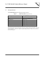
1
N.A.T. PMC-860-4S0 Technical Reference Manual
NPMC-860-4S0
CPU PMC Module
Technical Reference Manual V1.6
HW Revision 2.0
N.A.T. PMC-860-4S0 Technical Reference Manual
The NPMC-860-4S0 has been designed by:
N.A.T. GmbH
Kamillenweg 22
D-53757 Sankt Augustin
Phone: ++49/2241/3989-0
Fax: ++49/2241/3989-10
E-Mail: [email protected]
Internet: http://www.nateurope.com
Version 1.6
© N.A.T. GmbH
2
N.A.T. PMC-860-4S0 Technical Reference Manual
Disclaimer
The following documentation, compiled by N.A.T. GmbH (henceforth called N.A.T.), represents the current status of the product´s development. The documentation is updated on a
regular basis. Any changes which might ensue, including those necessitated by updated specifications, are considered in the latest version of this documentation. N.A.T. is under no obligation to notify any person, organization, or institution of such changes or to make these
changes public in any other way.
We must caution you, that this publication could include technical inaccuracies or typographical errors.
N.A.T. offers no warranty, either expressed or implied, for the contents of this documentation
or for the product described therein, including but not limited to the warranties of merchantability or the fitness of the product for any specific purpose.
In no event will N.A.T. be liable for any loss of data or for errors in data utilization or
processing resulting from the use of this product or the documentation. In particular, N.A.T.
will not be responsible for any direct or indirect damages (including lost profits, lost savings,
delays or interruptions in the flow of business activities, including but not limited to, special,
incidental, consequential, or other similar damages) arising out of the use of or inability to use
this product or the associated documentation, even if N.A.T. or any authorized N.A.T. representative has been advised of the possibility of such damages.
The use of registered names, trademarks, etc. in this publication does not imply, even in the
absence of a specific statement, that such names are exempt from the relevant protective laws
and regulations (patent laws, trade mark laws, etc.) and therefore free for general use. In no
case does N.A.T. guarantee that the information given in this documentation is free of such
third-party rights.
Neither this documentation nor any part thereof may be copied, translated, or reduced to any
electronic medium or machine form without the prior written consent from N.A.T. GmbH.
This product (and the associated documentation) is governed by the N.A.T. General Conditions and Terms of Delivery and Payment.
Note:
The release of the Hardware Manual is related
to a certain HW board revision given in the
document title. For HW revisions earlier than
the one given in the document title please
contact N.A.T. for the corresponding older
Hardware Manual release.
Version 1.6
© N.A.T. GmbH
3
N.A.T. PMC-860-4S0 Technical Reference Manual
Table of Contents
LIST OF TABLES .................................................................................................................................................5
LIST OF FIGURES ...............................................................................................................................................5
CONVENTIONS....................................................................................................................................................6
1
INTRODUCTION..........................................................................................................................................7
2
INSTALLATION .........................................................................................................................................10
2.1
SAFETY NOTE .........................................................................................................................................10
2.2
INSTALLATION PREREQUISITES AND REQUIREMENTS ..............................................................................11
2.2.1
Requirements..................................................................................................................................11
2.2.2
Power supply..................................................................................................................................11
2.2.3
Location Overview .........................................................................................................................12
2.3
AUTOMATIC POWER UP ..........................................................................................................................13
2.4
STATEMENT ON ENVIRONMENTAL PROTECTION .....................................................................................13
2.4.1
Compliance to RoHS Directive ......................................................................................................13
2.4.2
Compliance to WEEE Directive.....................................................................................................14
3
HARDWARE DETAILS.............................................................................................................................15
3.1
MEMORY MAP ........................................................................................................................................15
3.2
POWERQUICC PORT PINS USAGE ..........................................................................................................16
3.3
INTERRUPT STRUCTURE ..........................................................................................................................18
3.4
CONTROL / STATUS REGISTERS...............................................................................................................19
3.4.1
Status Register 1.............................................................................................................................19
3.4.2
Control/Status Register 2 ...............................................................................................................19
3.4.3
Status Register 3.............................................................................................................................20
3.5
IDL BUS OPERATION ..............................................................................................................................21
3.6
TIME DIVISION MULTIPLEX BUS STRUCTURE .........................................................................................21
3.7
S/T PORT SETUP .....................................................................................................................................22
4
CONNECTORS ...........................................................................................................................................23
4.1
CONNECTOR OVERVIEW .........................................................................................................................23
4.2
SWITCH SETTINGS ...................................................................................................................................23
4.3
PMC CONNECTOR P11 ...........................................................................................................................24
4.4
PMC CONNECTOR P12 ...........................................................................................................................25
4.5
PIN ASSIGNMENT OF THE PMC CONNECTOR -- P14 ( PMC I/O ) ........................................................26
4.5.1
Description P14 Signals.................................................................................................................27
4.5.2
SCbus IDs.......................................................................................................................................27
4.6
THE FRONT PANEL CONNECTORS (S1 - S4) ............................................................................................28
4.7
CONNECTOR JP1: MOTOROLA BACKGROUND DEBUG MODE (BDM) ....................................................29
4.8
CONNECTOR JP2: LATTICE PROGRAMMING PORT...................................................................................29
5
SOFTWARE APPLICATION NOTES .....................................................................................................30
5.1
5.2
5.3
HOST SETUP OF THE QSPAN II PCI BRIDGE ............................................................................................30
Q-BUS CONFIGURATION .........................................................................................................................32
EEPROM CONFIGURATION ....................................................................................................................32
Version 1.6
© N.A.T. GmbH
4
N.A.T. PMC-860-4S0 Technical Reference Manual
ANNEX A POWERQUICC CPU......................................................................................................................33
ANNEX B QSPAN IITM BUS BRIDGE ............................................................................................................35
ANNEX C RAM/ROM .......................................................................................................................................36
ANNEX D DOCUMENTATION REFERENCE .............................................................................................37
ANNEX E DOCUMENT’S HISTORY .............................................................................................................38
List of Tables
TABLE 1:
TABLE 2:
TABLE 3:
TABLE 4:
TABLE 5:
TABLE 6:
TABLE 7:
TABLE 8:
TABLE 9:
TABLE 10:
TABLE 11:
TABLE 12:
TABLE 13:
TABLE 14:
TABLE 15:
TABLE 16:
TABLE 17:
TABLE 18:
TABLE 19:
LIST OF USED ABBREVIATIONS ..........................................................................................................6
NPMC-860-4S0 MEMORY MAP ....................................................................................................15
POWERQUICC PORT PIN USAGE (PORT A) ....................................................................................16
POWERQUICC PORT PIN USAGE (PORT B) ....................................................................................16
POWERQUICC PORT PIN USAGE (PORT C) ....................................................................................17
POWERQUICC PORT PIN USAGE (PORT D) ....................................................................................17
NPMC-860-4S0 INTERRUPT STRUCTURE.......................................................................................18
STATUS REGISTER 1 ........................................................................................................................19
CONTROL/STATUS REGISTER 2 .......................................................................................................20
STATUS REGISTER 3 ........................................................................................................................20
PMC CONNECTOR P11 ...................................................................................................................24
PMC CONNECTOR P12 ...................................................................................................................25
PIN ASSIGNMENT OF THE PMC CONNECTOR -- P14.......................................................................26
DESCRIPTION P14 SIGNALS.............................................................................................................27
GENERAL PIN ASSIGNMENT OF THE FRONT-PANEL CONNECTORS S1 - 4 ........................................28
JP1 BDM AND IEEE 1149.1 CONNECTOR PINOUT OPTIONS ..........................................................29
LATTICE PROGRAMMING PORT .......................................................................................................29
NPMC-860-4S0 MEMORY MAP IN THE CONFIGURATION SPACE......................................................30
NPMC-860-4S0 MEMORY MAP IN THE PCI MEMORY SPACE ..........................................................31
List of Figures
FIGURE 1:
FIGURE 2:
FIGURE 3:
FIGURE 4:
FIGURE 5:
FIGURE 6:
Version 1.6
NPMC-860-4S0 ON A VMEBUS CARRIER ........................................................................................7
NPMC-860-4S0 BLOCK DIAGRAM ..................................................................................................8
LOCATION DIAGRAM OF THE NPMC-860-4S0 (SCHEMATIC)..........................................................12
TDM BUS ORGANISATION AND SYNCHRONISATION .......................................................................21
S/T PORT SETUP .............................................................................................................................22
CONNECTORS OF THE NPMC-860-4S0...........................................................................................23
© N.A.T. GmbH
5
N.A.T. PMC-860-4S0 Technical Reference Manual
Conventions
If not otherwise specified, addresses and memory maps are written in hexadecimal notation,
identified by 0x.
Table 1 gives a list of the abbreviations used in this document:
Table 1:
List of used Abbreviations
Abbreviation
Description
b
B
CPU
DMA
Flash
H.110
ISDN
K
LIU
M
MHz
ML53812
MPC860
PowerQUICC
Qbus
QSpan II
RAM
ROM
SCbus
Bit, binary
byte
Central Processing Unit
Direct Memory Access
Programmable ROM
Time-Slot Interchange Bus
Integrated Services Digital Network
kilo (factor 400 in hex, factor 1024 in decimal)
Line Interface Unit
mega (factor 10,0000 in hex, factor 1,048,576 in dec)
1,000,000 Herz
Oki H.110 Controller
Embedded processor from Motorola
MPC860
PowerPC processor bus
Tundra PCI Æ 60x bus interface device
Random Access Memory
Read Only Memory
Time-Slot Interchange Bus of the SCSA, subset of
H.110 bus
Serial Communication Controller of the MPC860
Signal Computing System Architecture
Synchronous Dynamic RAM
Serial Communication Controller of the MPC860
Static RAM
framer and line interface for basic rate ISDN
Time Division Multiplex
Time Slot Assigner
Time Slot Interchange
SCC
SCSA
SDRAM
SMC
SRAM
S/T port
TDM
TSA
TSI
Version 1.6
© N.A.T. GmbH
6
N.A.T. PMC-860-4S0 Technical Reference Manual
1 Introduction
The NPMC-860-4S0 is a high performance standard CPU PCI Mezzanine Card Type 1.
It can be plugged onto any carrier board supporting PMC standards:
Figure 1:
NPMC-860-4S0 on a VMEbus carrier
P2
P1
NVME-PMC
NPMC-8260-4E1
(Back View)
NPMC-860-4S0
(Back View)
The NPMC-860-4S0 has the following mayor features on-board:
• PowerQUICC MPC860 based Embedded PowerPC Architecture
• Front-panel I/O
• PCI Bus interface
• Single Slot VME/cPCI solution together with the PMC carrier board
Version 1.6
© N.A.T. GmbH
7
N.A.T. PMC-860-4S0 Technical Reference Manual
Figure 2:
PCI
Bus
QSPAN II
PCI <=>
Qbus
Bridge
QBus
4 / 16
MByte
DRAM
NPMC-860-4S0 Block Diagram
33/40/50 MHz
Oscillator
S0 Line
Interface
MPC860
Power QUICC
S0 Line
Interface
Connector
S0 Line
Interface
Connector
S0 Line
Interface
Connector
SPI
Connector
40/50/66/80 MHz
Flash
2 / 4 MByte
H.110 /
SCbus
IDL-Bus
TDM
ML53812
TSI
The onboard devices are in detail as follows:
• Memory
DRAM:
The NPMC-860-4S0 provides 4 or 16 MByte EDO DRAM onboard.
The DRAM is 32 bit wide.
Flash PROM:
The 8 bit boot Flash PROM provides a maximum capacity of 4
MByte.
• Interfaces
PCI:
The NPMC-860-4S0 includes a 32 bit 33 MHz PCI bus interface.
• I/O
The 4 S0 line interfaces are connected to the front panel connectors. The SCbus is
connected to the PCI I/O connector.
Version 1.6
© N.A.T. GmbH
8
N.A.T. PMC-860-4S0 Technical Reference Manual
• CPU
Depending on the assembled CPU type the PowerQUICC runs with a minimum
frequency of 50 MHz. (40 MHz, 66 MHz, or 80 MHz versions are optionally
available)
1.1 Specification
Processor
PowerQUICC MPC860
PMC-Module
Standard PCI Mezzanine Card Type 1
PCI to QBUS bridge
QSPAN II
I/O
4 RJ45 connectors
Main Memory
4 / 16 MByte EDO DRAM
Flash PROM
2 / 4 MByte Flash PROM, on-board programmable
Firmware
OK1, PSOS BSP, VxWorks BSP (on request)
Power consumption
3.3V 0,8A
5.0V 0,5A
Environm. conditions
Temperature (operating)
Temperature (storage)
Humidity
Standards compliance
Version 1.6
0°C to +50°C
-40°C to +85°C
5 % to 95 % noncondensing
PCI Rev. 2.2
P1386.1 / Draft 2.4
© N.A.T. GmbH
9
N.A.T. PMC-860-4S0 Technical Reference Manual
2 Installation
2.1
Safety Note
To ensure proper functioning of the NPMC-860-4S0 during its usual lifetime
take the following precautions before handling the board.
CAUTION
Malfunction or damage to the board or connected components
Electrostatic discharge and incorrect board installation and uninstallation can
damage circuits or shorten their lifetime.
• Before installing or uninstalling the board read this installation section
• Before installing or uninstalling the NPMC-860-4S0, read the Installation
Guide and the User’s Manual of the NPMC-860-4S0 carrier board
• Before installing or uninstalling the NPMC-860-4S0 on a carrier board or
both in a VME/cPCI rack:
- Check all installed boards and modules for steps that you have to take
before turning on or off the power.
- Take those steps.
- Finally turn on or off the power.
• Before touching integrated circuits ensure to take all require precautions for
handling electrostatic devices.
• Ensure that the NPMC-860-4S0 is connected to the carrier board via all
PMC connectors and that the power is available on both PMC connectors
(GND, +5V, and +3,3V).
• When operating the board in areas of strong electromagnetic radiation
ensure that the module
- is bolted the front panel or VME/cPCI rack
- and shielded by closed housing.
Version 1.6
© N.A.T. GmbH
10
N.A.T. PMC-860-4S0 Technical Reference Manual
2.2
Installation Prerequisites and Requirements
IMPORTANT
Before powering up
• check this section for installation prerequisites and requirements
2.2.1 Requirements
The installation requires only
• a carrier board for connecting the NPMC-860-4S0
• power supply
2.2.2 Power supply
The power supply for the NPMC-860-4S0 must meet the following specifications:
• required for the module:
- +3,3V / 0,8A typical
- +5,0V / 0,5A typical
Version 1.6
© N.A.T. GmbH
11
N.A.T. PMC-860-4S0 Technical Reference Manual
2.2.3 Location Overview
Figure 3 highlights the position of the important components. Depending on the board
type it may be that your board does not include all components shown in the location
diagram.
Figure 3:
Location diagram of the NPMC-860-4S0 (schematic)
PCI Bridge
PCI-Bus
CPU
B
D
M
S4
S3
S0 Framer
S2
PCI-I/O
TSI
DRAM DRAM
S1
Top View
S1
CPLD
FLASH
S2
S3
S4
Bottom View
Version 1.6
© N.A.T. GmbH
12
N.A.T. PMC-860-4S0 Technical Reference Manual
2.3
Automatic Power Up
In the following situations the NPMC-860-4S0 will automatically be reset and
proceed with a normal power up.
Voltage sensor
The voltage sensor generates a reset
• when +5V voltage level drops below 4,6V
• when +5V voltage level rises above 5,4V
• or when the carrier board signals a PCI Reset
Watchdog timer
Per factory default the watchdog timer of the PowerQUICC is disabled. If the
watchdog timer is enabled, it generates an non-maskable interrupt (NMI) followed by a reset when it is not retriggered by software ( see the PowerQUICC
users manual).
2.4
Statement on Environmental Protection
2.4.1 Compliance to RoHS Directive
Directive 2002/95/EC of the European Comission on the "Restriction of the use of
certain Hazardous Substances in Electrical and Electronic Equipment" (RoHS) predicts that all electrical and electronic equipment being put on the European market
after June 30th, 2006 must contain lead, mercury, hexavalent chromium, polybrominated biphenyls (PBB) and polybrominated diphenyl ethers (PBDE) and cadmium in
maximum concentration values of 0.1% respective 0.01% by weight in homogenous
materials only.
As these harzadous substances are currently used with semiconductors, plastics (i.e.
semiconductor packages, connectors) and soldering tin any hardware product is
affected by the RoHS directive if it does not belong to one of the groups of products
exempted from the RoHS directive.
Although many of hardware products of N.A.T. are exempted from the RoHS
directive it is a declared policy of N.A.T. to provide all products fully compliant to the
RoHS directive as soon as possible. For this purpose since January 31st, 2005 N.A.T.
is requesting RoHS compliant deliveries from its suppliers. Special attention and care
has been payed to the production cycle, so that whereever and whenever possible
RoHS components are used with N.A.T. hardware products already.
Version 1.6
© N.A.T. GmbH
13
N.A.T. PMC-860-4S0 Technical Reference Manual
2.4.2 Compliance to WEEE Directive
Directive 2002/95/EC of the European Comission on "Waste Electrical and Electronic
Equipment" (WEEE) predicts that every manufacturer of electrical and electronical
equipment which is put on the European market has to contribute to the reuse,
recycling and other forms of recovery of such waste so as to reduce disposal.
Moreover this directive refers to the Directive 2002/95/EC of the European Comission
on the "Restriction of the use of certain Hazardous Substances in Electrical and
Electronic Equipment" (RoHS).
Having its main focus on private persons and households using such electrical and
electronic equipment the directive also affects business-to-business relationships. The
directive is quite restrictive on how such waste of private persons and households has
to be handled by the supplier/manufacturer, however, it allows a greater flexibility in
business-to-business relationships. This pays tribute to the fact with industrial use
electrical and electronical products are commonly intergrated into larger and more
complex envionments or systems that cannot easily be split up again when it comes to
their disposal at the end of their life cycles.
As N.A.T. products are solely sold to industrial customers, by special arrangement at
time of purchase the customer agreed to take the responsibility for a WEEE compliant
disposal of the used N.A.T. product. Moreover, all N.A.T. products are marked
according to the directive with a crossed out bin to indicate that these products within
the European Community must not be disposed with regular waste.
If you have any questions on the policy of N.A.T. regarding the Directive 2002/95/EC
of the European Comission on the "Restriction of the use of certain Hazardous
Substances in Electrical and Electronic Equipment" (RoHS) or the Directive
2002/95/EC of the European Comission on "Waste Electrical and Electronic
Equipment" (WEEE) please contact N.A.T. by phone or e-mail.
2.4.3 Compliance to CE Directive
Compliance to the CE directive is declared. A ‘CE’ sign can ce found on the PCB.
2.4.4 Product Safety
The board complies to EN60950 and UL1950.
Version 1.6
© N.A.T. GmbH
14
N.A.T. PMC-860-4S0 Technical Reference Manual
3 Hardware Details
3.1
Memory Map
All addresses are set up by programming the corresponding Chip-Select Decoder of
the PowerQUICC.
Table 2:
Device
PCI
CS
Line
CS0
CS1
CS2
CS3
QSPAN
CS4
TSI
CS5
CS6
CS7
Flash-PROM
DRAM
I/O
Version 1.6
NPMC-860-4S0 Memory Map
Function
Notes
CS for FLASH
CS for DRAM
not used
CS for PMC Æ
PCI bus access
2/4 MByte Flash-Prom (8 Bit wide)
4/16 MByte EDO DRAM (32 Bit wide)
there are two PCI images available
selected by the IMS-Signal. This Signal
is generated by the Port D Bit 15
Qbus access to
the QSPAN II
Registers
CS for theTSI
not used
CPLD Registers, a number of control/status registers is
SCbus ID
implemented in a CPLD
© N.A.T. GmbH
15
N.A.T. PMC-860-4S0 Technical Reference Manual
3.2
PowerQUICC Port Pins Usage
Table 3:
PowerQUICC Port Pin Usage (Port A)
Signal Function
PowerQUICC Port A Pin
Description
DGNT1
DREQ4
MC TxD
MC RxD
IDL RxD
IDL TxD
TSI LSI1
PA15
PA14
PA13
PA12
PA11
PA10
PA9
TSI LSO1
PA8
IDL DCL
MC CLK
IDL DCL
DREQ3
DREQ2
IDL DCL
DREQ1
IDL DCL
PA7
PA6
PA5
PA4
PA3
PA2
PA1
PA0
GNT signal for S/T port 1
REQ signal for S/T port 4
Message Channel Transmit
Message Channel Receive
IDL Channel Receive
IDL Channel Transmit
Time Slot Assigner Bus data bit 1, output
of MPC860, input to ML53812 H.110
controller (Time Slot Interchange (TSI))
Time Slot Assigner Bus data bit 1, input
to MPC860, output of ML53812 H.110
controller (Time Slot Interchange (TSI))
IDL bus clock
Message Channel clock
IDL bus clock
REQ signal for S/T port 3
REQ signal for S/T port 2
IDL bus clock
REQ signal for S/T port 1
IDL bus clock
Table 4:
PowerQUICC Port Pin Usage (Port B)
Signal Function
PowerQUICC Port B Pin
Description
not used
SPI CLK
SPI RX
SPI TX
SDA_PQ
SCL_PQ
SMC1 TxD
SMC1 RxD
/SDACK1
not used
PZMP4*
PZMP3*
PZMP2*
PZMP1*
NT4*
NT3*
NT2*
NT1*
PB31
PB30
PB29
PB28
PB27
PB26
PB25
PB24
PB23
PB22
PB21
PB20
PB19
PB18
PB17
PB16
PB15
PB14
not used
SPI bus clock
SPI bus Receive
SPI bus Transmit
I2C data
I2C clock
SMC1 Channel Transmit
SMC1 Channel Receive
DMA Ack to QSpan II
not used
Point-to-Multi-Point channel 4
Point-to-Multi-Point channel 3
Point-to-Multi-Point channel 2
Point-to-Multi-Point channel 1
TE/NT selection channel 4
TE/NT selection channel 3
TE/NT selection channel 2
TE/NT selection channel 1
Signals with asterisk (*) are described in detail below.
Version 1.6
© N.A.T. GmbH
16
N.A.T. PMC-860-4S0 Technical Reference Manual
Table 5:
PowerQUICC Port Pin Usage (Port C)
Signal Function
PowerQUICC Port C Pin
Description
/DREQ1
DGNT4
DGNT3
DGNT2
/IRQST4
/IRQST3
/IRQST2
/IRQST1
IDL FS
IDL FS
IDL FS
IDL FS
PC15
PC14
PC13
PC12
PC11
PC10
PC9
PC8
PC7
PC6
PC5
PC4
DMA REQ from QSpan II
GNT signal for S/T port 4
GNT signal for S/T port 3
GNT signal for S/T port 2
Interrupt S/T port 4
Interrupt S/T port 3
Interrupt S/T port 2
Interrupt S/T port 1
IDL bus frame sync
IDL bus frame sync
IDL bus frame sync
IDL bus frame sync
Table 6:
PowerQUICC Port Pin Usage (Port D)
Signal Function
PowerQUICC Port D Pin
Description
IMSEL
LED4*
LED3*
LED2*
LED1*
not used
not used
not used
not used
SEL ST4*
SEL ST3*
SEL ST2*
SEL ST1*
PD15
PD14
PD13
PD12
PD11
PD10
PD9
PD8
PD7
PD6
PD5
PD4
PD3
Image Select for QSpan II
Front Panel LED
Front Panel LED
Front Panel LED
Front Panel LED
enable S/T port 4
enable S/T port 3
enable S/T port 2
enable S/T port 1
All port signals are tristate after Power-Up, until programmed differently. Output signals
marked with an asterisk (*) are described below in their (active) low state:
PZMP1 – 4 selection of point-to-point or point-to-multi-point connection,
low = point-to-point, high = point-to-multi-point
NT1 – 4
selection of TE/NT interface, low = TE (default), high = NT
LED1 – 4
lit when set low
SEL ST1 – 4 enable S/T ports, low = enabled
Version 1.6
© N.A.T. GmbH
17
N.A.T. PMC-860-4S0 Technical Reference Manual
3.3
Interrupt Structure
The NPMC-860-4S0 has the following interrupt structure:
Table 7:
NPMC-860-4S0 Interrupt Structure
Interrupt source
PowerQUICC Interrupt level
NC
for future use
QSPAN II
TSI
NC
NC
NC
for future use
IRQ-Level 0 (highest level)
IRQ-Level 1
IRQ-Level 2
IRQ-Level 3
IRQ-Level 4
IRQ-Level 5
IRQ-Level 6
IRQ-Level 7 (lower level)
The interrupt pins of the 4 S0 interface chips are routed to the port pins PC8 - PC11 of
the PowerQUICC, which are capable of generating interrupts. They are not routed to
dedicated IRQ-pins.
Version 1.6
© N.A.T. GmbH
18
N.A.T. PMC-860-4S0 Technical Reference Manual
3.4
Control / Status Registers
MPC860 CS7 (CSIO) selects the Control / Status Registers. The address range
decoded by hardware is 4 bytes. Larger address ranges mirror every 4 bytes.
Pure Status Registers are read-only, Status / Control Registers are read/write.
3.4.1 Status Register 1
Status Register 1 is accessed with address offset 0x0 to the CSIO base address
programmed for CS7. By means of this register the SCbus slot address is readable.
Table 8:
Bit
Number
Bit 7
Bit 6
Bit 5
Bit 4
Bit 3
Bit 2
Bit 1
Bit 0
Status Register 1
Read/Write Status Information
R
R
R
R
R
R
R
R
not used, reads as 0
not used, reads as 0
not used, reads as 0
SCbus slot address bit SL_4
SCbus slot address bit SL_3
SCbus slot address bit SL_2
SCbus slot address bit SL_1
SCbus slot address bit SL_0
3.4.2 Control/Status Register 2
Control/Status Register 2 is accessed with address offset 0x4 to the CSIO base address
programmed for CS7. By means of this register the status of the Timeout bits is
readable.
The Timeout bits are generated in a CPLD and mirror the activity of a TE port. If a TE
port is active, i.e. generates a SYNC signal to the logic, the corresponding Timeout bit
will read 0. If there is no (more) activity on this port, hence it is no longer suitable to
be source of local synchronisation, the corresponding Timeout bit will read 1.
These bits are implemented for applications where there is no TSI device assembled.
Additional information on this is available on request. As by default the TSI device is
assembled, the Timeout bits are not used in a standard application.
Also, for NT mode the FIX pins of the MC145574 S/T framers are settable/readable.
By means of these bits fixed / adaptive timing can be selected. Refer to the MC145574
manual for further details.
Version 1.6
© N.A.T. GmbH
19
N.A.T. PMC-860-4S0 Technical Reference Manual
Table 9:
Bit
Number
Bit 7
Bit 6
Bit 5
Bit 4
Bit 3
Bit 2
Bit 1
Bit 0
Control/Status Register 2
Read/Write Status Information
R
R
R
R
R/W
R/W
R/W
R/W
TIMEOUT bit of the MC145574 S/T framer port 4
TIMEOUT bit of the MC145574 S/T framer port 3
TIMEOUT bit of the MC145574 S/T framer port 2
TIMEOUT bit of the MC145574 S/T framer port 1
FIX bit of the MC145574 S/T framer port 4
FIX bit of the MC145574 S/T framer port 3
FIX bit of the MC145574 S/T framer port 2
FIX bit of the MC145574 S/T framer port 1
3.4.3 Status Register 3
Status Register 3 is accessed with address offset 0x8 to the CSIO base address
programmed for CS7. By means of this register the status of the TSEN pins of the
framers are readable. Refer to the MC145574 manual for further details.
Table 10:
Bit
Number
Bit 7
Bit 6
Bit 5
Bit 4
Bit 3
Bit 2
Bit 1
Bit 0
Version 1.6
Status Register 3
Read/Write Status Information
R
R
R
R
R
R
R
R
not used, reads as 0
not used, reads as 0
not used, reads as 0
not used, reads as 0
TSEN pin framer 4
TSEN pin framer 3
TSEN pin framer 2
TSEN pin framer 1
© N.A.T. GmbH
20
N.A.T. PMC-860-4S0 Technical Reference Manual
3.5
IDL Bus Operation
The four S/T ISDN framers, the MPC860 CPU TDM port, and the ML52812 H.110
TSI device are interconnected by an IDL bus. This IDL bus is mastered either by one
of the framers, or by the TSI device. The IDL bus master provides a Sync signal to a
LREF input of the TSI device, which generates local sync and clock for the IDL bus
from it. Any framer and the TSI device (if SCbus/H.110 bus slave) can be sync source
for the IDL bus. This is either decided be software, or by hardware implemented in a
CPLD, which choses an active TE port to be master, and switches to another active
one, if the one it is locked to goes inactive. If there is no active port at all, a free
running mode may be selected. Which port is sourcing a valid sync can also be read
from Control/Status Register 2 described above. The TIMEOUT bits for each port
read 1, if there is no carrier detected by the S/T chip, and reads 0, if the S/T chip locks
to the line.
3.6
Time Division Multiplex Bus Structure
The TDM bus structure connects the IDL bus of the framers to the local TDM bus
between CPU and TSI device, and to the backplane SCbus/H.110 bus. Timeslot
assignment is done within the framers and the CPU, switching of timeslots between
the different devices and the backplane is done by the TSI device. The TDM
interconnect structure is shown below:
Figure 4:
TDM Bus Organisation and Synchronisation
4 S/T Ports
MC145574
L
I
F
s
MPC
860
FS
CPLD
TCLK1-4
L_CLK, L_FS
IDL bus
PQ Rx / Tx
Version 1.6
© N.A.T. GmbH
ML53812
TSI
H.
1
1
0
21
N.A.T. PMC-860-4S0 Technical Reference Manual
3.7
S/T Port Setup
The following figure shows the connections of a S/T port device. All 4 port devices
are connected alike.
Figure 5:
S/T Port Setup
The IDL bus (described above) connects the framers to the TSI device. The S/T port
devices are programmed by the SPI port of the MPC860. DREQ, DGNT, SCP/GCIEN are connected to CPU port pins and thus programmable for any application’s
needs. The TCLK signal may fulfill different tasks: clock output, sync output in TE
mode, or FIX input in NT mode. Hence, the CPLD pins the TCLKx signals are
connected to may be programmed as input or output. This depends on the setting of
the NTx inputs connected to CPU port pins. If a channel is set to be NT (and the
corresponding CPU port pin NTx is set accordingly), the CPLD TCLKx pin will be an
output and drive the logic state programmed in the FIXx bits of the Control/Status
Register 2 described above.
Please refer to the MC145574 User’s Manual for additional information. Sample
driver code is available from N.A.T..
Version 1.6
© N.A.T. GmbH
22
N.A.T. PMC-860-4S0 Technical Reference Manual
4
Connectors
4.1
Connector Overview
Figure 6:
Connectors of the NPMC-860-4S0
J
P
2
P
12
S
W
1
JP1
S4
P
11
S3
S2
P
14
S1
NPMC-860-4S0
4.2
Switch Settings
Switch No. 1 of DIL Switch SW1 is used for a Background Debug Mode Tool. This is
a Power-Up option. If a BDM tool is to be used, Switch No. 1 of DIL Switch SW1
needs to be set to ON before powering up the module.
Default: Switch No. 1 of DIL Switch SW1 is set to OFF
Switch No. 2 of DIL Switch SW1 is used for factory test and its setting should not be
altered by the user.
Default: Switch No. 2 of DIL Switch SW1 is set to OFF
Version 1.6
© N.A.T. GmbH
23
N.A.T. PMC-860-4S0 Technical Reference Manual
4.3
PMC Connector P11
Table 11:
PMC Connector P11
Ext. Signal Pin No.
PCI-Signal PCI-Signal Pin No.
Ext. Signal
N.C.
GND
1
3
TCK
GND
-12V
/INT A
2
4
N.C.
N.C.
N.C.
GND
CLK
GND
/REQ
N.C.
PCI_AD28
PCI_AD25
GND
PCI_AD22
PCI_AD19
N.C.
/FRAME
GND
/DEVSEL
GND
N.C.
PAR
N.C.
PCI_AD12
PCI_AD09
GND
PCI_AD06
PCI_AD04
N.C.
PCI_AD02
PCI_AD00
GND
5
7
9
11
13
15
17
19
21
23
25
27
29
31
33
35
37
39
41
43
45
47
49
51
53
55
57
59
61
63
/INT B
bus mode 1
/INT D
GND
CLK
GND
/REQ
V (I/O)
AD28
AD25
GND
AD22
AD19
V (I/O)
/FRAME
GND
/DEVSEL
GND
/SDONE
PAR
V (I/O)
AD12
AD09
GND
AD06
AD04
V (I/O)
AD02
AD00
GND
/INT C
+5V
PCI_RSV1
PCI_RSV2
GND
/GNT
+5V
AD31
AD27
GND
CBE3
AD21
+5V
AD17
GND
/IRDY
+5V
/LOCK
/SB0
GND
AD15
AD11
+5V
/CBE0
AD05
GND
AD03
AD01
+5V
/REQ64
6
8
10
12
14
16
18
20
22
24
26
28
30
32
34
36
38
40
42
44
46
48
50
52
54
56
58
60
62
64
N.C.
/IRQQSPAN
N.C.
+5V
N.C.
N.C.
N.C.
/GNT
+5V
PCI_AD31
PCI_AD22
GND
/CBE3
PCI_AD21
+5V
PCI_AD17
GND
/IRDY
+5V
N.C.
N.C.
GND
PCI_AD15
PCI_AD11
+5V
/CBE0
PCI_AD05
GND
PCI_AD03
PCI_AD01
+5V
N.C.
Version 1.6
© N.A.T. GmbH
24
N.A.T. PMC-860-4S0 Technical Reference Manual
4.4
PMC Connector P12
Table 12:
PMC Connector P12
Ext. Signal Pin No. PCI-Signal
PCI-Signal
Pin No.
Ext. Signal
N.C.
N.C.
N.C.
GND
N.C.
N.C.
/RST
+3.3V
N.C.
PCI_AD30
GND
PCI_AD24
/IDSEL
+3.3V
PCI_AD18
PCI_AD16
GND
/TRDY
GND
/PERR
+3.3V
/CBE1
PCI_AD14
GND
PCI_AD08
PCI_AD07
+3.3V
N.C.
N.C.
GND
N.C.
GND
/TRST
TDO
GND
PCI_RSV3
PCI_RSV4
+3.3V
BUS-MODE 3
BUS-MODE 4
GND
AD29
AD26
+3.3V
AD23
AD20
GND
/CBE2
PCI_RESVD
+3.3V
/STOP
GND
/SERR
GND
AD13
AD10
+3.3V
PCI_RESV
PCI_RESV
GND
PCI_RESV
PCI_RESV
+3.3V
PCI_RESV
2
4
6
8
10
12
14
16
18
20
22
24
26
28
30
32
34
36
38
40
42
44
46
48
50
52
54
56
58
60
62
64
N.C.
N.C.
GND
N.C.
N.C.
+3.3V
N.C.
N.C.
GND
PCI_AD29
PCI_AD26
+3.3V
PCI_AD23
PCI_AD20
GND
/CBE2
N.C.
+3.3V
/STOP
GND
/SERR
GND
PCI_AD13
PCI_AD10
+3.3V
N.C.
N.C.
GND
N.C.
N.C.
+3.3V
N.C.
Version 1.6
1
3
5
7
9
11
13
15
17
19
21
23
25
27
29
31
33
35
37
39
41
43
45
47
49
51
53
55
57
59
61
63
+12V
TMS
TDI
GND
PCI_RSV
BUS-MODE 2
/RTS
+3.3V
PCI_RSV
AD30
GND
AD24
IDSEL
+3.3V
AD18
AD16
GND
/TRDY
GND
/PERR
+3.3V
/CBE1
AD14
GND
AD08
AD07
+3.3V
PCI_RESV
PCI_RESV
GND
ACK64
GND
© N.A.T. GmbH
25
N.A.T. PMC-860-4S0 Technical Reference Manual
4.5
Pin Assignment of the PMC Connector -- P14 ( PMC I/O )
Table 13:
Pin Assignment of the PMC Connector -- P14
ext. Signal
Pin No. PCI-Signal PCI-Signal Pin No. ext. Signal
MC
CT_D14
CT_D12
CT_D11
CT_D09
CT_D07
CT_D06
CT_D04
CT_D02
GND
CLKFAIL
SREF_8K
GND
SL_4
SL_2
SL_0
nc
nc
/C16CT_FRAME_A
CT_NETREF1
C2
CT_C8_B
CT_D16
CT_D18
GND
CT_D21
CT_D23
GND
CT_D26
CT_D28
CT_D30
1
3
5
7
9
11
13
15
17
19
21
23
25
27
29
31
33
35
37
39
41
43
45
47
49
51
53
55
57
59
61
63
Version 1.6
I/O
I/O
I/O
I/O
I/O
I/O
I/O
I/O
I/O
I/O
I/O
I/O
I/O
I/O
I/O
I/O
I/O
I/O
I/O
I/O
I/O
I/O
I/O
I/O
I/O
I/O
I/O
I/O
I/O
I/O
I/O
I/O
I/O
I/O
I/O
I/O
I/O
I/O
I/O
I/O
I/O
I/O
I/O
I/O
I/O
I/O
I/O
I/O
I/O
I/O
I/O
I/O
I/O
I/O
I/O
I/O
I/O
I/O
I/O
I/O
I/O
I/O
I/O
I/O
© N.A.T. GmbH
2
4
6
8
10
12
14
16
18
20
22
24
26
28
30
32
34
36
38
40
42
44
46
48
50
52
54
56
58
60
62
64
CT_D15
CT_D13
GND
CT_D10
CT_D8
GND
CT_D5
CT_D3
CT_D1
CT_D0
/FSYNC
SCLK
/SCLKx2
/C16+
SL_3
SL_1
nc
nc
CT_FRAME_B
CT_NETREF2
/C4
GND
CT_C8_A
CT_D17
CT_D19
CT_D20
CT_D22
CT_D24
CT_D25
CT_D27
CT_D29
CT_D31
26
N.A.T. PMC-860-4S0 Technical Reference Manual
4.5.1 Description P14 Signals
Table 14:
Description P14 Signals
Description General
MC
CT_D0 - 15
CLKFAIL
SREF_8K
SL_0 - 4
SCLKx2N
SCLK
FSYNCN
Description
VITA Spec.
identical
SD_0 - 15
identical
SREF8k
identical
SCLKx2
SCLK
FSYNC
SCBus message channel
SCBus/H.110 serial data stream 0 - 15
SCBus System Clock Fail signal
SCBus 8 kHz reference signal
SCBus ID
SCBus System clock x 2.
SCBus System clock.
SCBus 8 kHz frame signal
CT_D16 - 31
C2
/C4
/C16+
/C16CT_FRAME_A
CT_FRAME_B
CT_C8_A
CT_C8_B
CT_NETREF1
CT_NETREF2
not defined
not defined
not defined
not defined
not defined
not defined
not defined
not defined
not defined
not defined
not defined
H.110 serial data stream 16 - 31
H.110 2 MHz clock
H.110 4 MHz clock
H.110 16 MHz differential clock
H.110 16 MHz differential clock
H.110 8 kHz frame signal
H.110 8 kHz frame signal
H.110 8 MHz clock
H.110 8 MHz clock
H.110 8 kHz reference signal
H.110 8 kHz reference signal
Signal
For more details please refer to the VITA Extensions to ANSI/VITA 6 - 1994 SCSA.
4.5.2 SCbus IDs
In every SCSA system each SCSA device needs to have a unique ID.
The NPMC-860-4S0 supports reading the setting of SC IDs on the VMEbus / cPCI
bus backplane. This is done by reading Status Register 1 as described above.
Version 1.6
© N.A.T. GmbH
27
N.A.T. PMC-860-4S0 Technical Reference Manual
4.6
The Front Panel Connectors (S1 - S4)
The front panel connectors are RJ45 connector (8 pins). The 4 S0 line interfaces are
available on the pins of the front panel connectors. Table 5 shows the pin assignment.
Table 15:
General Pin Assignment of the Front-panel Connectors S1 - 4
RJ45 Pin
3
6
4
5
Signal NT
Signal TE
TX+
RX+
TXRX-
RX+
TX+
RXTX-
Rx/Tx can be swapped for TE/NT application by software. This feature, apart from
some others, needs reprogramming of the I/O port pins of the PowerQUICC. Refer to
the software documentation for further details.
RJ 45 male connector (front view)
1
Version 1.6
8
© N.A.T. GmbH
28
N.A.T. PMC-860-4S0 Technical Reference Manual
4.7
Connector JP1: Motorola Background Debug Mode (BDM)
The RS232 serial I/O port is available via a 20 pin SMD micro connector together
with the JTAG / BDM Port (see JP1 in the location overview).
The RS232 port is realised by the PowerQUICC communication controller SMC1.
Switch No. 1 of DIL Switch SW1 enables the Background Debug Mode (BDM), when
switched to ON. Default: Switch No. 1 of DIL Switch SW1 is set to OFF
Table 16:
GND
GND
+5V
JP1 BDM and IEEE 1149.1 Connector Pinout Options
VFLS0
GND
GND
/HRESET
+5V
FRZ
RXD_SMC1
TXD_SMC1
RXD_SMC1
TXD_SMC1
JTAG
BDM Port
PIN
1
2
3
4
5
6
7
8
9
10
11
12
13
14
15
16
17
18
19
20
/SRESET
DSCK
VFLS1
DSDI
DSDO
+3.3V
GND
GND
GND
TCK
TDI
TDO
TMS
+3.3V
GND
GND
GND
An adapter board with cable plugging into the 20 pin SMD micro connector is
available from N.A.T., that connects the JP1 connector to a standard 2-row, 10-pin,
100mil header used for BDM tool boxes, and routes the additional RS232 debug port
signals to a standard 9-pin SubD female connector.
4.8
Connector JP2: Lattice Programming Port
Connector JP2 connects the JTAG- or programming-port of the Lattice CPLD device.
Table 17:
Version 1.6
Lattice Programming Port
Pin No.
Signal
Signal
Pin No.
1
3
5
7
9
TCK
TMS
TDI
TDO
/TRST
nc
GND
+3.3V
GND
/ENABLE
2
4
6
8
10
© N.A.T. GmbH
29
N.A.T. PMC-860-4S0 Technical Reference Manual
5 Software Application Notes
5.1
Host Setup of the QSpan II PCI Bridge
In order to configure the NPMC-860-4S0 to work on the PCI-bus, the following steps
must be taken:
1.
Look up the address of the PCI-bus controller of the NPMC-860-4S0 in the
Configuration Space of the PCI-bus of the carrier board (please refer to the
manual for the carrier board).
The PCI-bus controller of the NPMC-860-4S0 occupies 256 Bytes in the
Configuration Space and you should see the following address map (first 64
bytes according to PCI specification 2.1):
Table 18:
Offset
0x0000
0x0004
0x0008
0x000c
0x0010
...
0x003c
NPMC-860-4S0 memory map in the configuration space
QSpan register
PCI_ID
PCI_CS
PCI_CLASS
PCI_MISC0
PCI_BSM
...
PCI_MISC1
Description of register
ID, start address configuration space
control and status
class
miscellaneous 0
base address for memory
...
miscellaneous 1
For more details regarding the QSpan II registers of the NPMC-860-4S0, please
refer to the QSpan II manual's register map (table A.1, Appp. A-2).
2.
Version 1.6
Now write - to the offset address 0x0010 (QSpan II register PCI_BSM, 32 bit) the start address of the NPMC-860-4S0 where it should appear in the memory
space of the carrier board’s PCI-bus. Please note, that all PCI register accesses
have to be done in little endian format.
The register image of the QSpan II should now be visible in the PCI memory
space.
© N.A.T. GmbH
30
N.A.T. PMC-860-4S0 Technical Reference Manual
Table 19:
Offset
0x0000
0x0004
0x0008
0x000c
0x0010
0x0014
...
0x003c
...
0x800
0x804
...
0x0ffc
NPMC-860-4S0 memory map in the PCI memory space
QSpan II register
PCI_ID
PCI_CS
PCI_CLASS
PCI_MISC0
PCI_BSM
...
PCI_MISC1
...
MISC_CTL
EEPROM_CS
...
-
Description of register
ID, start address QSpan register
control and status
Class
miscellaneous 0
base address for memory
QSpan unimplemented
...
miscellaneous 1
...
miscellaneous control
EEPROM control
...
QSpan reserved
3.
Initialize the register PBTI0_CTL for target image 0 and set the necessary
parameters:
The longword read/write access must be enabled by writing the PBTI0_CTL at
offset 0x0100 (image enable, block size BS[3:0] = 0110 = 4 MB, or BS[3:0] =
1000 = 16 MB, Q-bus destination port size DSIZE[1:0] = 00 = 32 bit).
4.
Set address translation decoding on register PBTI0_ADD at offset 0x0104 (host
system dependent):
Write the start address where the memory of the NPMC-860-4S0 module should
appear in the Memory Space of the PCI bus.
5.
Make certain that there are no address conflicts in your systems (set/check the
amount of the memory occupied by the NPMC-860-4S0 in the PCI memory
space).
Version 1.6
© N.A.T. GmbH
31
N.A.T. PMC-860-4S0 Technical Reference Manual
5.2
Q-Bus Configuration
Through the MISC_CTL register parameters for configurating the local bus (Q-Bus)
are set. The settings to be performed are system dependant. But, the following aspect
has to be taken into account in any case:
Setting of bit 0 (SW-RST) will cause a RESET on the Q-Bus, if the Q-BUS HRESET
signal is connected to the RESETO pin of the QSPAN (like for this module). The
RESETO signal follows the programming of the SW-RST bit directly, i.e. without any
delay in time. Therefore, if the MPC860 is to be reset by this means, the minimum
time period necessary to perform an orderly hardware reset of the MPC860 has to be
strictly obeyed. Otherwise the MPC860 may enter an undefined state. A time period of
100ms is recommended between the setting and resetting of this bit. In time-critical
applications this period may be reduced. Any value longer than 1ms should be
suuficient. 100ms is a period of time which is suitable and safe for resetting the Q-Bus
in all cases and for all CPU operating frequencies.
5.3
EEPROM Configuration
By means of register EEPROM_CS the Configuration-EEPROM may be read and
reprogrammed, which the QSPAN II uses for Power-Up – initialialisation. Please be
aware of the fact that programming the EEPROM with unsuitable values may cause
the PCI-Bus to hang completely.
NOTE: For more information, please refer to the QSpan II manual. Please make
certain that you use the correct endian format when writing into the QSpan II
registers.
Version 1.6
© N.A.T. GmbH
32
N.A.T. PMC-860-4S0 Technical Reference Manual
Annex A PowerQUICC CPU
Introduction
The MPC860 PowerPCTM Quad Integrated Communications Controller
(PowerQUICC) is a versatile one-chip integrated microprocessor and
peripheral controller combination that can be used in a variety of applications.
It particularly excels in both communications and networking systems.
The MPC860 is a PowerPC-based derivative of Motorola’s MC68360 (Quad
Integrated Communications Controller(QUICCTM ). The CPU on the MPC860
is a 32-bit PowerPC implementation that incorporates memory management
units (MMUs) and instruction and data caches. The communications processor
module (CPM) of the MC68360 QUICC has been enhanced with the addition
of the interprocessor-integrated-controller (I2C) channel. Moderate to high
digital signal processing (DSP) functionality has been added to the CPM. The
memory controller has been enhanced, enabling the MPC860 to support any
type of memory, including high performance memories and newer dynamic
random access memories (DRAMs).
Features
The following is a list of the MPC860´s important features:
• PowerPC single issue integer core
• High performance (52 K Dhrystone 2.1 MIPS @ 50MHZ, 3,3V, 1.3Watts
total power)
• MPC860 PowerPC system interface, including a periodic interrupt timer, a
bus monitor, and real-time clocks
• 32-bit address and data busses
• Flexible memory management
• 4-kbyte physical address, two-way, set-associative data cache
• 4-kbyte physical address, two-way, set-associative instruction cache
• Eight-bank memory controller
• System interface unit
• Communications processor module
- Embedded 32-bit RISC controller architecture for flexible I/O
- Interfaces to PowerPC core trough on-chip dual-port RAM and virtual
DMA channel controller
- Continuous mode transmission and reception on all serial channels
- Serial DMA channels for reception and transmission on all serial channels
- Parallel I/O-registers with open-drain and interrupt capability
Version 1.6
© N.A.T. GmbH
33
N.A.T. PMC-860-4S0 Technical Reference Manual
- Protocols supported by ROM or downloadable microcode and include,
but are not limited to, the digital portions of:
• Ethernet / IEEE 802.3 CS/DMA
• HDLC2 / SDLC and HDLC bus
• AppleTalk
• Signalling system #7 (RAM microcode only)
• Universal asynchronous receiver transmitter (UART)
• Synchronous UART
• Binary synchronous (BiSync) communications
• totally transparent
• totally transparent with CRC
• Profibus (RAM microcode only)
• Asynchronous HDLC
• DDCMP
• V.14 (RAM microcode only)
• X.21 (RAM microcode only)
• V.32bis datapump filters
• IrDA serial infrared
• Basic rate ISDN (BRI) in conjunction with SMC channels
• Primary rate ISDN (MH-Chip version only)
- Four hardware serial communications controller channels supporting the
above protocols
- Two hardware serial management channels
• Provide management for BRI devices as general circuit interface
controller in time division multiplexed channels
• Transparent and low speed UART operation
- I2C (microwire compatible) interface
• Supports master and slave modes
- Time slot assigner
• Supports one or two TDMA channels
• Bit or byte resolution
• Independent transmit and receive routing, frame synchronisation,
clocking able to be dynamically modified
• Can be configured by software for internal interconnection of CPM
serial channels
• Typically implements T1, CEPT, PCM highway, ISDN basic rate,
ISDN primary rate and user-defined TDMA serial interfaces
- Parallel interface port supports Centronics interfaces and chip-to-chip
interconnection
- Four independent baud rate generators and four input clock pins for
supplying clocks to SMC and SCC serial channels
- Four independent 16-bit timers which can be used as two 32-bit timers
Version 1.6
© N.A.T. GmbH
34
N.A.T. PMC-860-4S0 Technical Reference Manual
Annex B QSpan IITM Bus Bridge
Introduction
The QSpan IITM chip is a member of Tundra Semiconductor Corporation’s
family of PCI bus-bridging devices enabling board designers to bring PCIbased embedded products to market faster and for less cost.
The QSpan IITM is designed to gluelessly bridge the QUICCTM (MC68360), the
PowerQUICCTM as well as the MPC801 embedded controllers to PCI.
Features
The QSpan IITM has the following features:
• A direct connect interface to the PCI bus for Motorola’s QUICC
(MC68360), PowerQUICC(MPC860), M68040, the PMC821 and the
MPC861 embedded controllers;
• 32-bit PCI interface compliant with PCI Revision 2.1;
• Decoupled transfer technology: three 16-entry deep FIFOs buffer multiple
transaction in both directions, allowing zero wait state bursting on the PCI
and Motorola buses;
• IDMA peripheral support for QUICC and PowerQUICC;
• Flexible address space mapping and translation between the PCI and
Motorola buses;
• Programmable endian byte ordering;
• Two user-programmable slave images available for PCI access to the
Motorola buses;
• QSpan IITM control and status registers accessible from both PCI and
Motorola buses;
• PCI bus and Motorola buses can be operated at different clock frequencies;
Version 1.6
© N.A.T. GmbH
35
N.A.T. PMC-860-4S0 Technical Reference Manual
Annex C RAM/ROM
DRAM
The NPMC-860-4S0 provides an on-board DRAM (EDO-DRAM). This
memory is accessible from the PowerQUICC or the QSPAN II PCI-bridge
chip. The memory controller of the PowerQUICC is responsible for controlling
the DRAM. This flexible memory controller allows the implementation of
memory systems with very specific timing requirements.
The user is allowed to define different timing patters for the control signals that
govern a memory device. This patterns define how the external control signals
behave in a read-access request, write-access request, burst read-access
request, or burst write-access request. The user defines how the external
control signals toggle when the periodic timers reach the maximum
programmed value for refresh operation.
The memory capacity is 4 MByte ( optionally 16 MByte), the memory is 32 bit
wide. The access time of the EDO DRAM is 60 nsec for new accesses, the
access time within a row is 30 nsec ( bursting)
For different operating frequency of the MPC860 the user need to define
different timing patters.
The User Programmable Machine A (UPM A) controls the PowerQUICC and
the PCI accesses to the DRAM memory.
In the PowerQUICC Reset-state accesses to the DRAM will be inhibited.
Parity generation and check will not supported by the module
Boot Flash
The flash memory area is located on the PowerQUICC bus so that the reset
vector table in the boot flash is visible to the CPU after power on reset. The
boot flash memory has a size of 2 MByte (optionally 4 Mbyte) and can directly
be accessed by the CPU. The flash memory area is 8-bit wide organised.
The flash memory is a 5V only device. For programming the Flash is no extra
programming voltage necessary.
Programming the flash memory is possible in two ways:
- Programming the entire flash memory from the PCI-bus. The module must be
in the RESET-State.
- Programming the flash memory in the run state of the PowerQUICC.
Version 1.6
© N.A.T. GmbH
36
N.A.T. PMC-860-4S0 Technical Reference Manual
Annex D Documentation reference
PCI Interface chip
Company:
Title:
TUNDRA
QSPAN II (CA91CC862)
PCI to Motorola Processor Bridge Manual
MPC860 PowerQUICC
Company:
Title:
Motorola Inc.
MPC860 PowerQUICC
User’s Manual
Timeslot Switching Interface chip
Company:
Title:
Oki
ML53812-2 H.100/H.110 CT Bus System Interface and Time-Slot Interchange
User’s Manual
S0 Line Interface chip
Company:
Title:
Version 1.6
Motorola
MC145574 ISDN S/T Interface Transceiver
User’s Manual
© N.A.T. GmbH
37
N.A.T. PMC-860-4S0 Technical Reference Manual
Annex E Document’s History
Version
Date
Description
Name
0.9
10. Sept. 98
initial revision
mz
28.07.1999
Layout improvements
as
30.08.1999
correction of figures 3 and 4
added table 6 (debug port)
chapter 3.1 (QSPAN) reworked
adapted to HW revision 1.1
adapted to HW revision 2.0
Figure 4 corrected
Chapter 4 corrected (description of SW1)
‘Statement on Environmental Protection’ added
chapters 2.4.3. and 2.4.4. added
as
1.0
1.1
1.2
1.3
1.4
1.5
1.6
Version 1.6
21.06.2001
04.08.2003
05.09.2003
22.08.2005
19.01.2006
10.02.2006
06.06.2007
© N.A.T. GmbH
ga
ga
ga
ga
ga
ga
ga
38