1
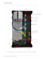
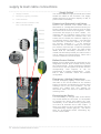
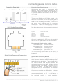
DMC810GL Leading Edge Dimmer/HF Ballast Controller Installation Manual contents Warning…………………………………………….. 2 Features…………………………………………….. 2 Important Safeguards…………………………….. 2 Internal View……………………………………….. 3 Mounting…………………………………….……… 4 Supply & Load Cable Connections.……………… 5 Connecting Serial Control Cables……………….. 6 Hardware Controls …………………………………7 Dimmable Lamps Chart……………………….….. 7 Troubleshooting……………………………………. 8 Specification………………………………………. 8 WMGD Pty Limited trading as Dynalite ABN 33 097 246 92 Unit 6, 691 Gardeners Road Mascot NSW 2020 Australia t +61 8338 9899 f +61 2 8338 9333 [email protected] philips.com/dynalite important safeguards Warning TO REDUCE THE RISK OF FIRE OR ELECTRIC SHOCK, DO NOT EXPOSE THIS DEVICE TO RAIN OR MOISTURE. DO NOT ENERGISE UNLESS THE FRONT COVER IS IN PLACE. THIS DEVICE MUST BE EARTHED. INSTALLATION, PROGRAMMING AND MAINTENANCE MUST BE CARRIED OUT BY QUALIFIED PERSONNEL features Single Phase Supply Simple supply requirement, single phase at 40A. 4 Dimmed Outputs Each dimmed 10A output is independently regulated, protecting loads from voltage surges and spikes. These outputs are overload protected by a single 10A circuit breaker shared with a switched output. 4 Switched Outputs Each switched output is rated at 10A. These outputs are overload protected by a single 10A circuit breaker shared with a dimmed output. 4 Control Outputs Each of the 4 optically isolated outputs can be configured to be either DALI Broadcast, 1-10V, or DSI control, covering the latest types of HF Fluorescent Ballasts and dimmable electronic transformers. These outputs can operate in tandem or independently of the switched outputs. Convection Cooled This device is naturally aspirated, requiring no mechanical cooling system when installed in accordance with these instructions. Many Control Options Control of this device can be from a combination of available methods, eg. serial control port, relay contacts, push button wall stations, infra red receivers and timeclocks. Easy high level interface to other popular AV control systems and Building Management Systems (BMS) is also available. Simple Installation Wall mount enclosure with mounting lugs facilitate installation. Cable knockouts are provided, at the top & side of the enclosure for supply and load cables, with safety extra low voltage (SELV) control section at the bottom. Warning – This is a class A product. In a domestic environment this product may cause radio interference, in which case the user may be required to take adequate measures. Instructions – We recommend that you read this Manual prior to installation, retain it and give the end user. Troubleshooting - If problems are encountered, check the “Troubleshooting” section on page 8. Special Programming – Once powered and terminated correctly this device will only operate in basic mode. A new Dynalite panel will turn on all lighting channels from button 1 and turn off from button 4 if network terminations are correct. Only once the full network is test correct can commissioning begin. Advanced functions can be commissioned via Envision software. If commissioning is required, contact your local distributor for details. Check Connections – Treat this device as a switchboard that has been shipped. Tighten all loadcarrying screw connections, as vibrations from transport can cause MCB and terminal block screws to become loose. Power Sources – This device should only be operated from the type of supply specified on the front panel. This device must be earthed. Dimmed and Switched Output Circuits – The load on a circuit should not exceed the specified capacity of 10A for a dimmed channel and 10A for a switched channel. Loads should be calculated to ensure that the overall maximum capacity of 40A (10A per pair of dimmed & switched channels) is not exceeded. Ballast Control Load Control Circuits – If this device is being used to control DALI, 1-10V or DSI HF Fluorescent Ballasts, a 2 core LV insulated control cable is required to be run to the loads, in addition to the mains feed. Note that the ballast control outputs are not SELV as they are not double insulated from mains. Load Type – Default is for ballast load control outputs to be 1-10V. Check to see what type of HF Fluorescent Ballasts are in the luminaries. When connecting 1-10V load control lines, pay attention that the correct polarity is maintained. Mounting Location – Device must be mounted right way up, on a vertical surface (refer to page 4 for mounting instructions). The specified minimum clearance of 100mm for all sides must be adhered to. Install in a dry, well-ventilated location. Controllers may emit some mechanical noise. Take this into account when deciding the mounting location. Data Cable – The recommended cable for connections to the serial port is screened, stranded RS485 data cable with three twisted pairs. Part numbers for various manufacturers are listed on page 6. This cable should be segregated from mains cables by a minimum distance of 300mm – subject to local wiring regulations. If anticipated cable runs are over 600 metres for serial cables, consult your dealer for advice. Do not cut or terminate live data cables. DMC810GL Installation Manual Rev E.docx 2 internal view Entry Gland Plate for Load Cables Circuit Breakers and Emergency Lighting line Outputs Dimmed or Switched 230V Outputs 40A Single Phase Supply Connections 4 x Side Entry Gland Knockouts DALI Broadcast, 1-10V or DSI Control Outputs Earth Link Accessory Port DyNet Port Network Socket Service Switch Service LED Low Voltage Cable Gland For spare parts, please call your nearest Dynalite Customer Service Centre, and specify: DMC810GL 3 DMC810GL Installation Manual Rev E.docx mounting Select a Suitable Location This device is designed for indoor use only. If installing in an external location, the DMC810GL must be housed in a suitable well-ventilated enclosure. Choose a dry location that will be accessible after the installation is complete. To ensure the cooling system functions correctly, the DMC810GL should only be mounted vertically, the right way up. The DMC810GL will generate heat when operating, approximately 2 Watts per Amp of load connected to the dimmed channels only, and requires an air gap of 200mm on each side and at the top and bottom of the device. This air gap is also required to ensure serviceability of the DMC810GL without complete removal from the mounting surface. This device may emit some mechanical noise. Take this into account when deciding the mounting location. Fixing the Device The DMC810GL has integral mounting brackets attached to the enclosure. The brackets are designed to accommodate 4 fixing screws up to 8mm diameter. The DMC810GL can be fixed to the wall without opening the cabinet or removing covers. Make sure no dust or other debris enters the device during installation. Do not leave the front cover off for any length of time. Excessive dust and dirt can degrade the cooling of internal components. Allow For Cable Entry Supply and load cables enter the enclosure at the top. If these cables are fed from below the mounting position, they should be routed around the enclosure to enter at the top. An alternative method is to stand the enclosure off from the mounting surface by mounting it on a cable tray or a Unistrut style product. The cables can then be routed between the enclosure and the mounting surface, and enter the enclosure via the cutout provided on the mounting face. The control cables enter at the bottom of the enclosure. Control cables should never be run in the mains voltage sections of the enclosure. DMC810GL Installation Manual Rev E.docx 4 supply & load cable connections Supply Cables 1. Supply Terminals 2. Emergency Lighting Terminals 3. Load Terminals 4. Ballast Control Terminals 1-10V, DSI, or DALI Broadcast 3. 2. 1 . The Phase & Neutral supply terminals are located toward the middle of the enclosure. The supply cables shall have a minimum capacity of 40A, to prevent cable overheating. Dimmed and Switched Load Cables Dimmed and switched load cables shall be terminated on 4 designated terminal blocks (one Phase & Neutral for each channel), and an Earth link located at the centre of the enclosure. These 2 connectors will accept up to 4mm cables. It is important that an individual output circuit is not overloaded. Calculate the intended load, and ensure that it is below the maximum capacity of an individual channel. Channels 1 – 4 are dimmed channels with a maximum capacity of 10 Amps per channel. Channels 5 – 8 are Switched channels, with a maximum capacity of 10 Amps per channel, total load per 2 channels protected by a single MCB is 10 Amps. The load neutral cables shall be individually connected to the neutral link terminals provided per channel with a max of 10Amps per neutral terminal. Never use a common neutral at a remote location. Ballast Control Cables 4. Ballast Control cables shall be terminated on the designated terminal block located directly below the Load terminals. These terminals are labelled CH9 to CH12, and can operate in tandem with the corresponding Load Outputs, or can be programmed to operate independently. 1-10V, DSI or DALI broadcast control are software configurable. Emergency Lighting Connections Connect emergency lighting circuit active to the load side on the circuit breaker for the relevant bank of 2 channels, as indicated by the front panel markings next to the circuit breakers. Do not remove any cables that may already be terminated, make sure device is isolated before removing cover. Energising the Device If it is necessary to energise load circuits before any control cables are connected, it is acceptable to energise the device and replace the cover immediately, as the default factory programming is to have all channels set to 100% output. If there is no output on any or all channels, see the “Troubleshooting” section (page 8). This device shall be de-energised before terminating any control or data cables. 5 DMC810GL Installation Manual Rev E.docx connecting serial control cables Connecting Data Cable Connect Data Cable in a ‘Daisy Chain’ Determine Your Requirements Serial ports are used to interconnect other dimmers, smart control panels, sensors and AV controllers. Serial port devices can be identified by 6 terminals, labelled: SHLD, GND, DATA+, DATA-, +VE, AUX. Serial Cable Connections RJ12 Socket Connections There is one RS485 port for DyNet signals, in the form of a RJ12 socket, on the front panel, which is used for the temporary connection of a PC or a DPP601 Portable Programmer. Data terminals on the control card shall be used for permanent connections. Cable for connections to the serial port shall be screened, stranded RS485 data cable, with three twisted pairs. Recommended cable types include: Belden: Dynalite: Garland: Hartland: M&M Cable: M&M Cable: Multicables: RS Components: 9503 DYNET-STP-CABLE MCP3S HCK603 B2003CS B9503CS AWM E120236 2092 20 368-687 One pair is paralleled for GND, one pair paralleled for +VE and one pair used for DATA+ and DATA Recommended Cable Colour Coding Green/White pair: Paralleled for GND Orange/White pair: Paralleled for +VE Blue/White pair: Blue for DATA+ White for DATABrown/White pair: Spare or for Join The colour-coding scheme used is not critical, as long as the same scheme is used throughout the installation. Serial Cable Permanent Connections Serial Cable Connecting Method The recommended connecting method is to „daisy chain‟ devices (starting at the first device, then looping in then out of devices, with a single cable terminating at the last device. There should not be any spurs or stubs, and only the first and last device shall terminate one cable. All other devices should terminate two cables). Devices may be wired in any order. The data cable should be segregated from any mains cables. A data cable that is connected to an energised dimmer is live. Do not cut or terminate live data cables. If the data cable has to cross over any mains cables, it is recommended that it do so at a 90 angle to minimise noise coupling. Sufficient insulation shall be provided, subject to local regulations. DMC810GL Installation Manual Rev E.docx 6 preset programming using the program key AUX Input - This is a dry contact interface that is active low. The dry contact is connected between the AUX and GND terminals on the DyNet connector strip. The function of the AUX input is programmable. Ensure that the cable length between the dry contact and terminal strip is no longer than 2 metres. Service LED - The Service LED has 3 signalling modes, which are useful for troubleshooting: Blinking slowly (1Hz) = Normal Operation Blinking fast (4Hz) = Network Activity Detected On = Fault Service Switch - The Service Switch has three functions: 1 push = Transmit Network ID 3 pushes = All Channels 100% Push & hold for 4 sec = Reboot Top Set - This adjusts the maximum output that all other control sources can select, ie: if the Top Set is fully clockwise, 100% selected by a control source will give 100% output. If it is fully anti-clockwise, 100% selected by a control source will give 50% output. This control is useful for extending lamp life and can be operated without any form of network control, effectively turning the device into a stand-alone power conditioner and lamp protector. Accessory Module Socket - Accepts plug in multi function accessory modules for optional features such as nd additional dry contact inputs, 2 DyNet port and Time clocks. Consult your distributor for details on the available accessory modules. dimmable lamps chart INCANDESCENT LAMPS TUNGSTEN HALOGEN LAMPS FLUORESCENT LAMPS (26mm, T8) FLUORESCENT LAMPS (16mm, T5) COMPACT FLUORESCENTS 7 Incandescent lamps are easily dimmed using all Dynalite controllers. The soft start and voltage limit features will extend lamp life. Lamp life can be further extended using the voltage limit adjustment. Tungsten halogen and other transformer loads are easily dimmed using all Dynalite controllers. The soft start and surge limiting features will protect lamps against premature failure. Lamp life can be extended using the voltage limit adjustment. Ensure that transformer is designed for dimming. 26mm slimline tubes can be dimmed to as low as 1% using a dimmable electronic ballast. No de-rating is necessary with electronic ballasts. Contact your Dynalite dealer for more information. 16mm slimline tubes can be dimmed to as low as 1% using a dimmable electronic ballast. No de-rating is necessary with electronic ballasts. Contact your Dynalite dealer for more information. Must be dimmed with electronic ballasts which accept 1-10V, DSI or DALI broadcast. Only some types of CFL lamps can be successfully dimmed. Best results are achieved with dimmable HF ballasts DMC810GL Installation Manual Rev E.docx Trouble shooting Check the following list. If you are still unable to rectify the situation, contact your nearest Dynalite office. A complete list of distributors worldwide can be found on the Internet at: www.philips.com/dynalite Please ensure that you have completed the following prior to calling our technical support department. Check all symptoms in the Troubleshooting list Check for any deviations between the installation and the installation instructions Make a list of the model numbers of all devices used in the system SYMPTOM PROBABLE CAUSE ACTION Dimmer does not operate at all. No Service LED activity. Power supply indicator LED on PCB not lit. Incorrect connection of mains supply, or no power available. Check power supply to dimmer. Check Line and Neutral input connections. Power supply indicator LED lit, but no Service LED activity. Supply voltage too low, short circuit on network. Control PCB faulty. Check supply voltage is at least 75% of rated voltage. Check 12V terminal voltages. Disconnect network bus and restore power. Replace control PCB. Dimmer will not respond to control panel push buttons. Control panel incorrectly wired or incorrect configuration. Check operation of LEDs on control panel. Push button on panel and study response of service LED. Dimmer operates properly but circuit breakers keep tripping. Instant tripping: - short circuit on load. Delayed tripping: - dimmer overloaded. Check load wiring for short circuits. Verify dimmer loading with current tester (don‟t forget to de-rate for low power-factor loads and transformer losses). Check that the breaker terminals are tight. Fluorescent lights won‟t dim. Wrong type of ballast or ballast incorrectly wired. Check ballast type. Check actual wiring against ballast manufacturer‟s diagram. Check 110V/DSI, DALI Broadcast settings. specification Supply: Outputs: Protection: Regulating Device: Switching Device: Power Conditioning; Interference Suppression: Rise Time: Control Inputs: User Controls: Internal Controls: DyNet DC Supply +VE: Preset Scenes: Supply Terminals: Output Terminals: Cable Entries: Diagnostic Functions: (DTK600, DLight or BAS interface required for displaying and analysing diagnostic data) Compliance: Ambient Temperature: Construction: Dimensions: Weight: 230V ±14% 50/60Hz Single Phase at 40A 4 x 10A dimmed (leading edge phase control) outputs 4 x 10A switched outputs 4 x HF ballast control outputs selectable to DALI Broadcast, 1-10V DC, DSI 4 x 10A 6kA single pole thermal magnetic circuit breakers Triac 600V, 40A nom. 400A surge Relay 16A nom. (resistive), Fluorescent 800A surge, Incandescent 165A surge, Regulated outputs Over voltage protection Surge protection Brownout/Sag protection Spike protection Soft Start Iron powder toroidal choke 100S at 230V 1 x RS485 DyNet/DMX512 serial port 1 x programmable dry contact AUX input Service Switch Diagnostic LED Programmable Logic Controller Dynalite Accessory Module enabled 200mA (supply for approx 10 panels) 170 Line, Neutral – 2 x 10mm2 max conductor size Line, Neutral for each channels 1-8 2 x 4mm2 max conductor size Earth link bar provided 0V/DSI/DALI, +V/DSI/DALI for channels 9-12 1 x 2.5mm2 max conductor size Mains – 8 x 25mm dia. knockout Data – 1 x 25mm dia. knockout Device Online/Offline status Circuit breaker trip reporting (optional) Circuit run time tracking CE, C-Tick, 0 - 40C ambient temperature, 0% to 95% RH non condensing. Alloy/Steel wall mount case with epoxy finish Height 370mm x Width 215mm x Depth 170mm (excludes wall brackets) 7.5 Kilograms DMC810GL Installation Manual Rev E.doc Specifications and design subject to change without notice. Dynalite Manufactured by WMGD Pty Ltd (ABN 33 097 246 921). All rights reserved. Dynalite, Dimtek, DyNet and DLight and associated logos are the registered trademarks of Dynalite Intelligent Light Pty Ltd. Not to be reproduced without permission. Unit 6, 691 Gardeners Road Mascot NSW 2020 Australia Tel: +61 2 8338 9899 Fax: +61 2 8338 9333 E-mail: [email protected] Web: Philips.com/dynalite DMC810GL Installation Manual Rev E.docx 8