1
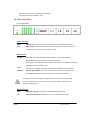
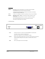
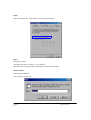
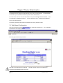
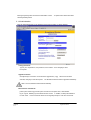
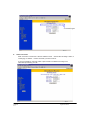
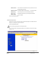
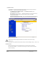
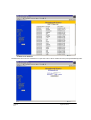
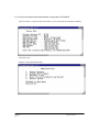
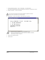
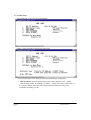
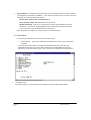
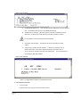
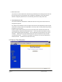
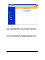
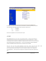
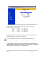
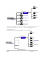
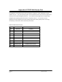
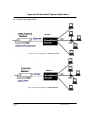
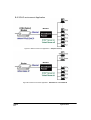
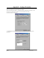
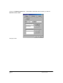
EE400-R Broadband Router
User Manual
EE400-R
P0
GigaFast Ethernet.
Copyright
The contents of this publication may not be reproduced in any part or as a whole, stored, transcribed in
an information retrieval system, translated into any language, or transmitted in any form or by any
means, mechanical, magnetic, electronic, optical, photocopying, manual, or otherwise, without prior
written permission.
Trademarks
All products and company brand names are trademarks or registered trademarks of their respective
companies. They are used for identification purposes only. Specifications are subject to be changed
without prior notice.
GigaFast Ethernet.
1100 S Hatcher Ave #C
City of Industry, CA 91748 USA
Tel: 626-964-2960
Fax: 626-964-2690
e-mail: [email protected]
http://www.gigafast.com
Copyright © 1998 - 2002, GigaFast Ethernet. All Rights Reserved.
EE400-R
P1
GigaFast Ethernet.
FCC Interference Statement
This equipment has been tested and found to comply with the limits for a Class B digital device pursuant
to Part 15 of the FCC Rules. These limits are designed to provide reasonable protection against radio
interference in a commercial environment. This equipment can generate, use and radiate radio
frequency energy and, if not installed and used in accordance with the instructions in this manual, may
cause harmful interference to radio communications. Operation of this equipment in a residential area is
likely to cause interference, in which case the user, at his own expense, will be required to take whatever
measures are necessary to correct the interference.
CE Declaration of Conformity
This equipment complies with the requirements relating to electromagnetic compatibility, EN 55022/A1
Class B, and EN 50082-1. This meets the essential protection requirements of the European Council
Directive 89/336/EEC on the approximation of the laws of the member states relation to electromagnetic
compatibility.
EE400-R
P2
GigaFast Ethernet.
CONTENTS
CHAPTER 1 INTRODUCTION ............................................................................................ 5
1.1 FEATURES..................................................................................................... 5
1.2 PACKAGE CONTENTS .................................................................................... 6
1.3 SYSTEM REQUIREMENT ................................................................................... 6
1.4 PANEL DESCRIPTION....................................................................................... 7
1.4.1 Front Panel.............................................................................................. 7
1.4.2 Rear Panel............................................................................................... 8
CHAPTER 2 INSTALLATION .............................................................................................. 9
2.1 HARDWARE CONNECTION TO WAN.................................................................. 9
2.2 HARDWARE CONNECTION TO LAN.................................................................. 9
2.3 NETWORK SETTING IN ADMINISTRATOR’S COMPUTER...................................... 10
CHAPTER 3 DEVICE ADMINISTRATION...................................................................... 13
3.1 WEB BASED CONFIGURATION........................................................................... 13
3.1.1 Device Information.................................................................................. 14
3.1.2 Administration.......................................................................................... 15
3.1.3 EZ Setup - WAN....................................................................................... 16
3.1.4 EZ Setup - LAN........................................................................................ 20
3.2 TELNET/CONSOLE CONFIGURATION ................................................................. 24
3.2.1 Device Information and Administration configuration in EE400-R ....... 25
3.2.2 WAN Setup................................................................................................ 27
3.2.3 LAN Setup................................................................................................ 29
3.2.4 Advanced function .................................................................................. 30
CHAPTER 4 ADVANCED FIREWALL FUNCTION........................................................ 32
4.1 ACCESS CONTROL ............................................................................................ 32
4.2 SERVICE TIME ALLOCATION ............................................................................. 33
4.3 URL KEYWORD BLOCKING.............................................................................. 35
4.4 VIRTUAL SERVER.............................................................................................. 36
4.5 DMZ ............................................................................................................... 37
4.6 MULTIPLE DMZ HOST .................................................................................... 38
CHAPTER 5 TROUBLESHOOTING................................................................................. 41
5.1 COMMON PROBLEMS & SOLUTIONS .................................................................. 41
5.2 FREQUENTLY ASKED QUESTIONS..................................................................... 42
Appendix A TCP/IP Well-Known Port......................................... 44
Appendix B Illustrated Typical Application.................................. 45
EE400-R
P3
GigaFast Ethernet.
Appendix C Cabling and Pin Assignment............................................ 48
Appendix D Configure IP manually................................................... 51
Appendix E Technical Information ................................................... 53
EE400-R
P4
GigaFast Ethernet.
Chapter 1 Introduction
Congratulations on your purchase of this outstanding Broadband Router EE400-R. This product is the
perfect option to connect a group of PCs to a high-speed Broadband Internet connection or to an
Ethernet based Backbone (ETTH/ETTB: Ethernet To The Home/Building). Configurable as a DHCP
server, this product is the only externally recognized server device on your local area network (LAN).
Thus even a non-technical person will easily configure it to meet the different applications.
This product does not only provide a complete solution to share the Internet bandwidth, it also serves as
an Internet Firewall to protect your LAN data from being accessed by outside intruders/hackers (Figure
1-1).
Since all incoming data packets have been analyzed/monitored, they may be filtered-out and
recorded as an intrusion event.
It can also be configured to block some internal LAN users’ access
to the Internet for management purpose.
Figure 1-1 Secure Internet Access via Cable/DSL Modem.
1.1 Features
Connects to 10/100Mbps Broadband (cable or DSL) modem or Ethernet backbone for Internet
Multiple WAN connection type:
Static IP (NAT/routing mode),
DHCP client (e.g.
cable
modem), PPPoE (e.g. Dial-up ADSL service) and PPP
Supports PPP (e.g. V.90/ISDN modem) dial-up.
Equipped with a 4-port 10/100Mbps switched Hub for LAN users.
DHCP Server/ DNS proxy support (can save an extra PC/Server in LAN).
All the networked computers in LAN can retrieve TCP/IP setting (IP address, subnet mask,
gateway, DNS,IP¡K) automatically from this device.
EE400-R
P5
GigaFast Ethernet.
Simultaneously acts as both DHCP Server on the LAN and a DHCP Client on the WAN for
easy application.
Connects multiple LAN PCs to the Internet with only one dynamic-assigned IP address
(NAT mode) or a range of legal IP address (NAT/Routing mode)
Web-based Configuring
Configurable through any networked computer’s web browsers using Internet Explorer or
Netscape browser.
Allow/Deny remote administration through WAN connection by Web browser.
Support Telnet / Console administration from a networked computer in LAN.
Firewall capability to protect LAN PCs from outside intruder access/attack.
Avoid unwanted packets from WAN and provides a system event log to record intrusion
information. (date/time, source IP address)
LAN user Access privilege
Administrator can arrange interior LAN users’ access privilege to Internet by IP address,
TCP/IP port service, URL name keywords and 24-hour time zone.
Virtual Server (Port forwarding) function
Internet servers (WWW, FTP, E-mail) in LAN could be virtually exposed to WAN for outside
Internet user access. This is a useful and secure network deployment for Internet servers.
DMZ (De-Militarized Zone) Host
Administrator can completely expose a host PC in LAN to the Internet without any firewall
protection mechanism. This option allows a full two-way communication between the local
host PC and remote Internet node. (ex. bi-directional games, video/audio conferences)
Multi DMZ Host support
In static IP configuration with a range of legal IP addresses, the Administrator could completely
expose several host PCs in the LAN to the Internet according to LAN/WAN IP address mapping.
1.2 Package Contents
One broadband router unit
One CD-ROM (manual/utility)
One power adapter
One CAT-5 UTP cable
One RS232 cable
1.3 System Requirement
One Ethernet based broadband Internet connection (i.e. cable/DSL modem or other router)
One PC with a NIC card and Installed TCP/IP protocol stack.
EE400-R
P6
GigaFast Ethernet.
Microsoft Internet Explorer (or Netscape) web browser.
All TCP/IP networked computers in LAN.
1.4 Panel Description
1.4.1 Front Panel
Device Indicators
PWR
PWR (power): The Power LED illuminates whenever the EE400-R is powered on.
RDY
RDY (ready): The RDY LED blinks once per second when it is working normally, or it
will blink faster or be off if there is something wrong.
WAN Indicators
Lnk/Act
Lnk (link): ON means WAN (DSL/Cable modem) is connected to EE400-R.
Act (activity): Blinking means there is data communication.
If the LED is continuously illuminated, it means WAN device is successfully connected or
EE400-R’s WAN port is working now.
10/100
Indicates 10 or 100Mbps wire speed corresponding to WAN port. (On is 100Mps)
FDX/COL
FDX (Full Duplex Mode): On means the current connection is on full duplex mode.
COL (Collision): Blinking means the connection is experiencing collisions.
The WAN port has NIC card type pin assignment, so it can connect to a HUB device
or connect directly to a PC with a crossover cable. (Please refer to Appendix C-1 to
check your WAN devices)
Modem Indicators
MR
MR (Modem Ready): serial port connected with MODEM correctly.
CD
CD (Carrier Detection): MODEM is on-line now and detects data carrier.
EE400-R
P7
GigaFast Ethernet.
LAN Indicators
Lnk/Act
Lnk (link): ON means LAN PC/device is connected correctly to EE400-R.
Act (activity): Blinking means there is data communication.
If the LED is continuously illuminated, it means the LAN device is successfully
connected or the port is working now.
10/100
Indicates 10 or 100Mbps wire speed corresponding to each port. (On is 100Mps)
FDX/COL
FDX (Full Duplex Mode): On means the current connection is on full
duplex mode.
COL (Collision): Blinking means the connection is experiencing collisions.
Note: infrequent collisions are normal. If the COL LED is lit too often,
there may be a problem with your connection.
1.4.2 Rear Panel
Serial
Serial port connector. It is used to connect with MODEM or console terminal
The options could be configured via WEB browser.
(Please refer to Appendix C-2 for pin assignment & cabling)
Default
Reset to factory default settings button. Hold it down continuously about 5 seconds to
reset the hardware settings into factory default. The default LAN IP becomes
192.168.8.1.
5VDC
EE400-R
P8
Where you will plug the AC-DC Power adapter.
GigaFast Ethernet.
Chapter 2 Installation
Attach the power cord into the oulet first and follow the sections below to setup the WAN/LAN connection.
2.1 Hardware Connection to WAN
Connect the network cable from the Cable/ DSL modem to the WAN port of the EE400-R (Figure 2-1). If
the Link/Act light is off, check that the power and the network cable between the Cable/DSL modem and
WAN port are plugged in correctly.
(Please refer to Appendix C for detailed cabling and pin assignment).
Figure 2-1 The hardware connection of WAN interface for EE400-R.
2.2 Hardware Connection to LAN
Connect the network cable from your computer’s Ethernet port to one of EE400-R’s 4 LAN ports
(Figure 2-2). If it is correctly connected, the corresponding Link/Act light will be lit.
Figure 2-2 Diagram of connections between router and computers.
** If you are connecting the LAN port to another hub or switch, use a crossover RJ-45 cable.**
Once everything is connected correctly, hold down the reset button for 5 seconds to ensure that the
EE400-R is in factory default condition.
EE400-R
P9
GigaFast Ethernet.
2.3 Network Settings in Administrator’s computer
In order to configure the EE400-R with a networked PC in the LAN, it is necessary for the administrator
to have correct network settings in the PC, so that the communication between the EE400-R and the
administrator ‘s PC is possible. The following description assumes that the EE400-R is in factory default
condition. (If not, hold the reset button down for at least 5 seconds).
The EE400-R LAN interface IP will
become 192.168.8.1 and the DHCP server for LAN users is on with an IP range from 192.168.8.17 to
192.168.8.128 by default.
Follow the procedures to set your computer as a DHCP Client. (If the fixed IP mode for administrator’s
computer is desired, please refer to Appendix E.)
Step1:
Click the Start button, select Settings, and then choose Control Panel.
Double click the Network icon.
Click the Configuration tab. Select the TCP/IP protocol option that is associated with your network
card/adapter.
EE400-R
P 10
(See blue box below.)
Click the Properties button.
GigaFast Ethernet.
Step2:
Click the IP Address tab.
Select Obtain an IP address automatically.
Step3:
Click [ok] to continue.
The system may ask you to restart.
If so, restart now.
After restart, the connection should be established. Please check it as follows.
Windows 9x/Me :
Click Start and select Run…
Type “winipcfg”, and click [ok].
EE400-R
P 11
GigaFast Ethernet.
All Ethernet adapter information is shown in this window.
Check if you get an IP address like 192.168.8.x where x is any number between 17 and 128.
that the default gateway is 192.168.8.1.
Then check
Windows XP/2000/NT4 :
Click Start and select Run… Type in “command”, which will bring up the MS-DOS command window. Type
“ipconfig /all” to check the Ethernet adapter information.
All Ethernet adapter information is shown in this window.
Check if you get an IP address like 192.168.8.x where x is any number between 17 and 128.
the default gateway is 192.168.8.1.
Then check that
If everything is correct, the network should be working now. Please go to the next Chapter to continue setup.
If something is wrong, please refer to Chapter 5 for troubleshooting.
EE400-R
P 12
GigaFast Ethernet.
Chapter 3 Device Administration
The EE400-R can be configured via Web browser, telnet, and a console terminal.
The administrator
can choose any one of the three methods to perform device administration.
No matter which method is used, this administration only allows one login session at a time.
in consideration of database consistency.
This is
If anyone else tries to log in, it will fail and the EE400-R
will pop-up an alert message.
The following description also assumes the EE400-R is in factory default condition.
3.1 Web Based Configuration
Open the web browser and type http://192.168.8.1 into the browser’s address box.
This IP address is
the EE400-R’s LAN interface address.
The main page should show up as below.
This page is not protected by any password. It is used to provide a place for all LAN users to
inquire about the EE400-R’s status at any time.
EE400-R
P 13
GigaFast Ethernet.
Type in the default Administrator password, ”admin”. Then click enter to login.
3.1.1 Device Information
After login, the first page is the Device Information of the EE400-R.
This page shows the detailed status of the EE400-R and displays the current WAN’s information
about dial-up duration and traffic (bytes count)
EE400-R
P 14
GigaFast Ethernet.
Clicking the [Clear] button will clear the WAN traffic counter. To update to the latest information
click the [Refresh] button.
3.1.2 Administration
Click the Administration link on the left frame of this page to assign or change settings.
Change password:
Type in your old password, new password, and confirm it. Then click [OK] to send
the request.
Upgrade Firmware:
Click [browse] to choose the correct firmware upgrade file (*.upg). When a file has been
selected, click [Go] to send the request. The EE400-R’s firmware will be upgraded immediately.
After a moment, EE400-R will restart automatically.
Miscellaneous Commands:
[View system events log] records system events such as system start , administrator
log-in / log-out, dial/hang-up and hacker intrusion events.
In addition, it stamps the date/time
for each event. Each event will be shown chronologically except for a few time-out events.
EE400-R
P 15
GigaFast Ethernet.
Click [View System Log] to browse the log record.
This page stores lots of useful information.
diagnostic tool for troubleshooting.
This function provides the administrator with a convenient
Furthermore, it provides detailed intruder/hacker information.
You can click [Refresh] to update these events and click [Back] to return to the Administration page.
[Clone MAC]:
Duplicates the MAC address of the administrator’s PC into the WAN MAC
address of the EE400-R.
[Reset to Default]:
Resets the system settings to factory default, and restart automatically
after completion.
[Restart System]:
Forces the EE400-R to restart immediately.
3.1.3 EZ Setup - WAN
Click the EZ Setup-WAN link in the left frame.
There are 4-connection types in this page.
Only one connection type must be configured because the network is connected to the Internet
via one method at a time. It can be changed later if your connection type changes.
EE400-R
P 16
GigaFast Ethernet.
4 connection types
A.
Static Connection
Static connection is used when a fixed IP address is used. Certain ISPs will assign a static, or
unchanging, IP address. Please check with your ISP to find out.
If you have a Static IP, select the “static” option and fill in the blanks according to the
information provided by your ISP.
EE400-R
P 17
GigaFast Ethernet.
WAN IP Address:
The IP Address of the EE400-R as seen by external users on the
Internet (including your ISP).
WAN Subnet Mask: The EE400-R WAN IP address ranges. (i.e. 255.255.255.248)
WAN Gateway:
The ISP will provide you with the Gateway IP Address.
WAN 1st DNS:
DNS (Domain Name Server). ISP will provide this address.
WAN 2nd DNS:
The second DNS.
Click the [Save&Restart] button.
B. DHCP Client Connection
DHCP Client connection means that the ISP will dynamically assign an IP address and other
settings, so no settings are required to be filled in.
Click the [Save&Restart] button.
This connection type is popular for most Cable modems.
After the save & restart, the assigned IP address can be checked on the “Device Info” page.
(refer to 3.1.1)
EE400-R
P 18
GigaFast Ethernet.
C. PPPoE Connection
If the EE400-R is connected to the Internet through a DSL line, ask the ISP if they use PPPoE for
dial-up service. If they do, select the PPPoE option then fill in:
Your PPPoE account and PPPoE password. (The PPPoE Service Name may be
optional depending on the ISP).
Dial on Demand: Choose this option. The EE400-R will attempt to connect with the ISP, if (1)
there is at least one LAN user trying to access the Internet or (2) the current WAN
connection is disconnected.
Auto disconnect when Idle Time is over __ sec: fill in a time period in seconds if you want to
disconnect automatically when your Internet connection is idle more than that period of time.
Click the [Save&Restart] button.
After the save & restart, the assigned IP address can be checked on the “Device Info” page.
(refer to 3.1.1)
If something is wrong, please browse the system event log to check the dial/log-in activity.
(refer to 3.1.2)
D. PPP Connection
PPP (point-to-point protocol) is the most popular protocol to access the Internet via telephone
line and modem (v.90/ISDN). If your Internet connection type is a modem connection, select PPP
and fill in the following:
EE400-R
P 19
GigaFast Ethernet.
ISP phone No., PPP account (username), and PPP password.
Dial on Demand & Auto disconnect is the same as in PPPoE.
Modem Initial String: Type the AT commands if it is needed. (Some ISDN/v.90 modem
need this) ex. Type”W2” to request MODEM to report carrier speed instead of DTE speed.
(This works only for most Rockwell/conexant v.90 modems)
Click the [Save&Restart] button.
After the save & restart, the assigned IP address can be checked on the “Device Info” page.
(refer to 3.1.1)
If something is wrong, please browse the system event log to check the dial/log-in activity.
3.1.4 EZ Setup - LAN
Click the EZ setup-LAN link on the left frame to setup LAN.
EE400-R
P 20
GigaFast Ethernet.
(refer to 3.1.2)
LAN IP Address: The IP address of the EE400-R as it is seen by the internal LAN user.
The DHCP Server is enabled by default.
If the LAN IP is changed, the administrator may lose the connection with the EE400-R when they are not
in the same LAN segment. Administration operation will not work until they are in the
same segment again. (Do this by releasing and renewing the IP address on the administrator’s PC)
1. DHCP Server Enabled
Choose this option if you want the EE400-R to assign IPs to computers on the network automatically.
EE400-R
P 21
GigaFast Ethernet.
DNS Proxy:
LAN computers get their DNS server from the EE400-R first.
The EE400-R will
search the ISP’s DNS automatically.
IP pool from 192.168.8.x to 192.168.8.x: Whenever there is a request, the DHCP server
will offer unused IPs from the IP address pool to the requesting computer.
The end address must be greater than the start address.
Lease time: the assigned IP will be valid during the lease interval.
Assign fixed IP to MAC: If there are some computers, like web/E-mail server, which will
be assigned a fixed IP by the DHCP server, you can set those computers with their own
predefined IP. Those computers will be identified by their MAC address.
Click [DHCP Client List] to show the DHCP Client list.
EE400-R
P 22
GigaFast Ethernet.
2. DHCP Server Disabled
Disable DHCP Server function of EE400-R. You just have to fill in LAN IP Address and then press [Save&Restart] button.
EE400-R
P 23
GigaFast Ethernet.
3.2 Telnet/Console Configuration
The telnet-based configuration is almost the same as console configuration. The difference is that
console configuration requires being connected to the EE400-R with your computer by null modem
cable (Please refer to Apendix C-2).
Telnet configuration can only be used via Lan.
Click Start and select Run… Type “telnet” and when the window opens, type “open 192.168.8.1”.
The terminal parameters should be set to 115200 8-N-1(baud rate 115200, 8 data bit, No parity, 1 stop
bit). When the RDY LED is blinking regularly, press the Enter key once.
In general, the Telnet/console configuration is menu-driven.
Enter the password (“admin” is the default) and press Enter to login. The main menu is shown below.
Type the number of each item to select your choice.
EE400-R
P 24
GigaFast Ethernet.
3.2.1 Device Information and Administration configuration in EE400-R
When you select 1 to enter the device information, you can see the device information as follows:
Press Esc to exit.
Select 2 to enter administrator setup.
EE400-R
P 25
GigaFast Ethernet.
1.
Change administrator password: Press 1 for this setting. The system will ask
you to enter your old password, enter your new password, and retype your new password to confirm.
2.
Upgrade new firmware:
Press 2 for this setting.
You must use a telnet program with file transfer capability to upgrade your firmware
Window’s built-in terminal does not provide this feature.
3.
Set Date/Time: Press 3 for this setting.
A.
B.
Date/Time needs to be initialized every time the EE400-R is reset.
Whenever the administrator logs on via web browser, the date/time is calibrated
automatically according to the login PC.
4.
Reset to factory default and restart
5.
Restart system
EE400-R
P 26
Set the date and time separately.
GigaFast Ethernet.
3.2.2 WAN Setup
Select WAN setup to select the correct configuration.
Press 1 to select the WAN Connection type option menu.
Four connection types can be chosen by entering the available type number(A~D).
1.
Static IP address: Static connection is used when a fixed IP address is used. Certain
ISPs will assign a static, or unchanging, IP address. Please check with your ISP to find out.
If you have a Static IP, select the “static” option and fill in the blanks according to the
information provided by your ISP.
EE400-R
P 27
GigaFast Ethernet.
WAN IP Address:
The IP Address of EE400-R as seen by external users on the
Internet (including your ISP).
WAN Subnet Mask: The EE400-R WAN IP address ranges. (i.e. 255.255.255.248)
WAN Gateway:
ISP will provide you with the Gateway IP Address.
WAN 1st DNS:
DNS (Domain Name Server). ISP will provide this address.
WAN 2nd DNS:
The second DNS.
When all settings are complete, don’t forget to type Y to restart the system.
2.
DHCP Client:
DHCP Client connection means that the ISP will dynamically assign an IP address and
other settings, so no settings are required to be filled in.
If your Internet connection type is a DHCP client type, such as a Cable modem, you should
select this option
When all settings are complete, don’t forget to type Y to restart the system.
3.
PPP over Ethernet: PPPoE (point to point protocol over Ethernet) connection means that
personal users can browse Internet through DSL-based broadband connection. If you are
connected to the Internet through a DSL line, check your ISP if they use PPPoE. If they do,
choose the PPPoE option and type in:
Your PPPoE account and PPPoE password.
(The PPPoE Service Name may be
optional depending on the ISP).
Dial on Demand: If you choose this option, EE400-R will attempt to connect with the ISP, if (1)
there is at least one LAN user trying to access the Internet and (2) the current WAN
connection is disconnected.
Auto disconnect when idle over sec: Fill in a time period in seconds if you want to
disconnect automatically when your Internet connection is idle more than the specified period of time.
When all settings are complete, don’t forget to type Y to restart the system.
EE400-R
P 28
GigaFast Ethernet.
4.
Dial-up Network: PPP (point-to-point protocol) is the most popular protocol to access the Internet
via telephone line and modem (v.90/ISDN). If your Internet connection type is a modem connection,
select PPP and enter the following information:
ISP phone No., PPP account and PPP password.
Dial on Demand & Auto disconnect is the same as PPPoE.
Modem Initial String: Type the AT commands if it is needed. (Some ISDN/v.90 modems
need this) ex. Type”W2” to request MODEM to report carrier speed instead of DTE speed.
( This works only for most Rockwell/conexant v.90 modems)
When all settings are complete, don’t forget to type Y to restart the system.
3.2.3 LAN Setup
The LAN Setup configuration in a telnet environment has 2 items.
1.
LAN IP Address:
computers.
type in the IP address of the EE400-R as it is seen by the internal LAN
If Telnet is used and the LAN IP is changed, the administrator may lose connection with
The EE400-R when they are not in the same LAN segment, so administration will not work
until they are in the same segment again. (This can be done by releasing and renewing the IP.)
.
2.
LAN DHCP Server:
Choose this option if you want the EE400-R to assign IPs to LAN computers automatically.
EE400-R
P 29
GigaFast Ethernet.
DHCP Server enabled
A.
Enable/Disable DNS Proxy:
first.
B.
LAN computers get their DNS server from the EE400-R
The EE400-R will search the ISP’s DNS automatically.
Set DHCP IP Pool Range: Whenever there is a request, the DHCP server will
allocate an unused IP from the IP address pool to the requesting computer.
The end address must be greater than the start address.
C.
Set DHCP Lease Duration: the assigned IP will be valid during the lease
duration.
D.
Assign fixed IP address by MAC address:
If there are computers, such as
web/E-mail servers, which will be assigned fixed IPs by the DHCP server,
you can set those computers with their own predefined IP. Those computers will
be identified by their MAC address.
DHCP Server disabled
Select 1 to toggle between disable and enable DHCP Server.
3.2.4 Advanced function
1.
Access control
Under the main menu, type A to enter into access control.
EE400-R
P 30
GigaFast Ethernet.
Allow/Deny Respond to Ping from WAN:
Allow or Deny responding if there are any Ping packet sent to WAN of the EE400-R.
Allow/Deny Web Management from WAN:
This function allows the administrator to configure the EE400-R from the outside
Internet with a browser directly.
In order to reserve HTTP service (port 80), which
is used for virtual servers, the remote web administration function utilizes another port
64511 instead. (e.g. http://211.79.244.45:64511 ).
2.
User command:
This is reserved for diagnostic purposes
EE400-R
P 31
GigaFast Ethernet.
Chapter 4 Advanced Firewall Function
Besides the native protection features from NAT, the EE400-R provides advanced functions which
are popular in most firewall devices such as deny PING, block service port, URL keyword blocking,
virtual server, DMZ and intrusion event log.
(recorded in the EE400-R internal buffer, please refer to
3.1.2)
4.1 Access Control
“Access control” allow you to control the WAN-to-LAN or LAN-to-WAN access capability.
Click the Access Control link in the left frame.
1.
There you will see the 3 options shown below.
Respond to Ping from WAN:
Allow or Deny responding if there is any PING packet sent to the WAN of the EE400-R.
This is very useful to avoid Internet intruders/hackers from probing the computer. Most likely,
the hacker will not start to attack.
2.
Web Management from WAN:
This function allows the administrator to configure the EE400-R from the outside Internet with
the browser directly.
In order to reserve HTTP service (port 80), which is used for virtual
server function, the remote web administration function utilizes another port 64511 instead.
(e.g. http://211.79.244.45:64511 ).
EE400-R
P 32
GigaFast Ethernet.
3. Block Client in LAN:
This function is used to inhibit some LAN clients (by IP address) from accessing Internet resources.
Since all LAN clients are recognized by their IP addresses, regardless of if the LAN client’s IP
address is assigned by DHCP server or manual setting, this function always works well.
4. Filter Packets from LAN:
This function allows the administrator to inhibit LAN users from using some Internet services for
management purposes.
For example, if the EE400-R is used in a SOHO environment and the administrator wants to inhibit
LAN users from using Telnet services (like BBS, on-line chat), then it is easily achieved by blocking
all packets to service port 23.
Another example would be blocking service port 110 (POP3) which will inhibit LAN users from
checking/retrieving outside Internet E-Mail accounts. This is very useful when WAN connection
type is Dial-On-Demand (like PPPoE/PPP).
Then, the EE400-R can auto-disconnect at normal
conditions. Otherwise the periodic E-Mail checking will cause the EE400-R to keep the WAN
connection alive forever. Therefore, in this situation, the LAN user can only use E-Mail servers
inside the network. (if a POP3 server exists in the LAN).
4.2 Service Time Allocation
EE400-R
P 33
GigaFast Ethernet.
“Service Time Allocation” allows the administrator to control the EE400-R’s LAN-to-WAN if the service is
available or disabled at any time. This feature is implemented through two mechanisms.
One method is to specify the maximum continuous service period. This is primarily used for
parental control in home/family applications.
It can protect children from surfing the Internet
continuously for more than a pre-defined period X. Meanwhile, the EE400-R will still stop
service until period Y is expired.
EE400-R
P 34
GigaFast Ethernet.
The other mechanism is simply dependent on a daily time zone. This means the EE400-R’s
LAN-to-WAN service is on or off according to a predefined daily schedule table.
4.3 URL Keyword Blocking
In order to prevent LAN users from accessing specific websites, the EE400-R provides a function to
perform such a filtering mechanism.
The administrator can enter the URL keywords of which
websites are to be rejected. Then the EE400-R will reject any websites which have URL names
that match or partially match.
For example, if the keyword is xyz, then www.xyz.com, ftp.xyz.com, xyz.abc.com are all blocked.
EE400-R
P 35
GigaFast Ethernet.
Click the [Save&Restart] button after listing the keywords.
4.4 Virtual Server
Generally, NAT based routers/firewalls filter out all unrecognized packets from the WAN to protect your
Internal LAN computers; therefore, all LAN computers behind the EE400-R are invisible to the outside
Internet. However, some Internet servers (like WWW, FTP, E-mail) should be visible and accessible
by the outside Internet. As a result, the EE400-R provides Virtual Server functions to meet this demand.
addition, the EE400-R also protects the servers and all other computers in the LAN simultaneously.
Since all the Internet servers always handle the fixed TCP/UDP service port number (like WWW is 80,
FTP is 21) any packets from the WAN which have a destination port number that matches a virtual
server’s port, then these packets will be forwarded to the pre-defined LAN’s IP.
The destination
port number is also kept the same.
EE400-R
P 36
GigaFast Ethernet.
In
For example, if you have an FTP server (port 21) at 192.168.8.5, a mail server (port 110) at 192.168.8.6,
and a VPN server at 192.168.8.7, then you need to specify the virtual server as:
21
I
192.168.8.5
110
I
192.168.8.6
1723 I
192.168.8.7
Please refer to Appendix A for some well-know service ports.
4.5 DMZ
DMZ (DeMilitarized Zone) is a zone, which is not protected by firewall.
It means that all computers in
the DMZ are dangerous and subject to be attacked/accessed by Internet intruders/hackers.
However
the advantage is that all computers in the DMZ are completely exposed to Internet, thus all of them gain the
full access right privilege to the outside Internet. In such a case, theoretically, all Internet applications
should be compatible with them because there is no interference from the firewall.
There are
more
and
more
Internet applications
need
2-way access
right (like
video and/or
conference, on-line game..). EE400-R provide the similar features to make some computers in LAN to
have unrestricted 2-way access privilege. As a result, all computers in DMZ are most compatible with
Internet applications. Thus, they seem to be dangerous in comparison with those other computers in the
LAN.
EE400-R
P 37
GigaFast Ethernet.
audio
The EE400-R always allows a computer in the LAN to be logically exposed to the Internet with
unrestricted 2-way communication.
This is very useful whenever you encounter some incompatible
applications (such as 2-way online games). The DMZ feature can often avoid these problems.
The following shows a single DMZ host is allowed due to the single WAN IP address shown. (for
example, WAN connection type is DHCP client, PPPoE and PPP)
4.6 Multiple DMZ Host
If the WAN connection type is static and there is a range of IP addresses assigned to the WAN interface
instead of a single IP (please refer to section 3.1), then the EE400-R allows 4 computers in the LAN
to become DMZ hosts.
EE400-R
P 38
GigaFast Ethernet.
In general, the mechanism for multiple DMZ hosts is based on the mapping relation between the WAN IP and
the LAN IP (shown below). These DMZ host IPs will skip NAT port translation handling to gain
unrestricted 2-way communication capability.
WAN IP1
IEE400-RI
LAN IP1
(DMZ host1)
WAN IP2
IEE400-RI
LAN IP2
(DMZ host2)
WAN IP3
IEE400-RI
LAN IP3
(DMZ host3)
WAN IP4
IEE400-RI
LAN IP4
(DMZ host4)
Most likely the multiple DMZ hosts are applied in a router-to-router inter-connection SOHO environment
(please refer to Figure 4-2). It is less popular with home users due to the “range of WAN IP address”
because IP addresses are important and expensive resources now.
Some ISPs provide leased line services (DSL is a common one) to subscribers, and can offer a
range of IP addresses for subscription. In this case, there are two types of connection configurations.
One is Bridging mode, the other is Routing mode.
For example, if the ISP provides IPs 210.65.226.1 through 210.65.226.7 (subnet mask 255.255.255.248),
then the subscriber can have 6 computers at most accessing the Internet simultaneously. With the EE400-R,
additional computers can access the Internet. (Please refer to Figure 4-1)
EE400-R
P 39
GigaFast Ethernet.
EE400-R
Figure 4-1 Bridging mode
Unfortunately, the multiple DMZ host will not work with the Figure 4-1 configuration because the EE400-R can
only handle one IP address, not 5 IP addresses. In such conditions, the bridging mode option is
available for Multiple DMZ.
The following Figure 4-2 is a typical Router-to-Router inter-connection configuration.
EE400-R
Figure 4-2 Routing mode
EE400-R
P 40
GigaFast Ethernet.
Chapter 5 Troubleshooting
5.1 Common Problems & Solutions
This section provides possible solutions to problems regarding the installation and operation of
the EE400-R.
Try to find answers here if there is any problem when you setup the device.
Check your device and settings step by step.
1.
Connecting to the EE400-R LAN port fails
Check to see that the EE400-R’s LAN connections are properly connected and the unit is powered on.
Set the EE400-R to factory default condition.
Ensure that your PC and the EE400-R are on the same network segment. If you are not sure,
initiate the DHCP function to let the PC get an IP address automatically.
Make sure that the IP address of your PC is within the default range of 192.168.8.17 to
192.168.8.128.
Check the Subnet Mask . It should be set to 255.255.255.0 to match the EE400-R.
2.
Failed to configure the EE400-R through web
Check the cable connection to the EE400-R LAN port and see if the status LEDs on the front
panel are functioning properly.
In Windows9x /ME series, run “winipcfg” to check the client side by clicking on the [Start] button
then select [Run]. The PC should show:
3.
1)
IP address: 192.168.8.xxx (xxx is from 17 to 128).
2)
Submask: 255.255.255.0
3)
Default Gateway IP: 192.168.8.1
“Time out error” message pops up when I enter a URL or IP address.
Check if other PCs are working. If they are, check that your workstation’s IP settings are
correct (IP address, Subnet Mask, Default gateway and DNS.)
If the PCs are configured correctly, but still not working, check the EE400-R. Check that it is
connected and ON. Connect to it and check it’s settings. (If you cannot connect to it, check the
LAN and power connections.)
If the EE400-R is configured correctly, check your Internet connection to see that it is working
properly.
4.
Can’t obtain an IP address from my Cable or DSL modem.
Check if the WAN LEDs are lit.
Power down your DSL or Cable modem for a few seconds. Turn it back on. After the modem
EE400-R
P 41
GigaFast Ethernet.
goes through its self-test, check to see if you now have an IP address.
Your ISP may require a Mac address. Check if it is correct.
5.2 Frequently Asked Questions
1. Where is the EE400-R installed on the network?
Typically, the EE400-R is installed between the Cable/DSL modem and the LAN.
Plug the EE400-R
WAN port into the Cable/DSL modem’s Ethernet port.
2.
Does the WAN connection of the EE400-R support 100Mb Ethernet?
Yes, the EE400-R supports 100Mb Ethernet on its WAN port.
Since the EE400-R WAN is an
auto-sensing 10/100 port, it is also compatible with 10Mb only WAN devices.
3. What is NAT (Network Address Translation) and what is it used for?
NAT translates multiple IP addresses in the private LAN to one public address that is sent out to the
Internet. NAT has 2 functions:
-
It adds a level of security since the IP address of a PC connected to the private LAN is never
transmitted on the Internet.
-
It allows the EE400-R to be used with low cost Internet accounts, such as DSL or cable modems,
where only one IP address is provided by the ISP. Users can have many private addresses behind
a single address.
4. If installation fails, what can I do?
Reset your cable/DSL modem by powering the unit off for 20 seconds and then turn it back on. Once it
has completed its tests, reset the EE400-R by holding down the reset button for at least 5 seconds with the
power on and try installation again.
5. What type of firewall is the EE400-R equipped with?
The EE400-R uses NAT and TCP/IP packet inspections.
6. What can I do if I am unable to access the web configuration screen for this router?
You may have to remove proxy settings on your Internet browser or remove dial-up settings on your
browser. (If you use PPPoE or PPP WAN connection)
7. What is DMZ (DeMilitarized zone) ?
DMZ allows one IP address (computer) to be exposed to the Internet.
Some applications require
multiple TCP/IP ports to be open. It is recommended that you set your computer with a static IP if you
want to use DMZ.
EE400-R
P 42
GigaFast Ethernet.
8.
Does the EE400-R pass PPTP or actively route PPTP sessions?
Yes, this router allows PPTP packets to pass through.
9. Is the EE400-R cross-platform compatible?
Yes, any platform that supports Ethernet and TCP/IP is compatible with the EE400-R.
10. Can I use my own public IPs and Domain or do I have to use the IPs provided by the
router?
You can customize your own IPs through configuration of this router.
11. What are the advanced features of the EE400-R?
The advanced features of the router include Access Control, URL Blocking, Virtual
Server, and DMZ.
EE400-R
P 43
GigaFast Ethernet.
Appendix A TCP/IP Well-Known Port
Any application or process that uses TCP for its transport is assigned a unique identification number
called a TCP port.
TCP ports specify the path of communications between client and server applications.
These ports are numbered beginning with zero.
Port numbers for client applications are dynamically
assigned by the operating system when there is a request for service. Port numbers for server
applications are pre-assigned by the Internet Assigned Numbers Authority (IANA) and do not change,
The following is a short list of some well-known port numbers.
Table A-1 Well-Known TCP ports
Port No.
Name (TCP)
Description
20
FTP-DATA
FTP(data)
21
FTP
FTP(command)
23
TELNET
Terminal Connection
25
SMTP
SMTP
53
DOMAIN Name
Domain Name Server
79
FINGER
Finger
80
HTTP
Web
110
POP3
POP3
113
AUTH
Authentication Service
139
NETBIOS-SSN
NETBIOS Session Service
1723
PPTP
Point to Point Tunneling Protocol
EE400-R
P 44
GigaFast Ethernet.
Appendix B Illustrated Typical Application
B-1 Home User Application
EE400-R
Figure B-1 Home user application - DSL/Cable modem
EE400-R
Figure B-2 Home user application - ISDN/V.90 Modem
EE400-R
P 45
GigaFast Ethernet.
B-2 SOHO environment Application
EE400-R
Figure B-1 SOHO environment application – Simple IP sharing
EE400-R
Figure B-2 SOHO environment application - DHCP Server in the EE400-R
EE400-R
P 47
46
GigaFast Ethernet.
EE400-R
Figure B-5 SOHO environment application - DHCP Server in LAN
EE400-R
P 47
GigaFast Ethernet.
Appendix C Cabling and Pin Assignment
C-1 RJ-45
There are different grades, or categories, of twisted-pair cabling.
highly recommended.
Category 3 is a good second choice. Straight-through cables are used for
connecting computers’ NIC card to a hub.
hub.
Category 5 is the most reliable and is
Crossover cables are used for connecting a hub to another
(The EE400-R provides a built-in uplink/normal switch.
Uplink mode is crossed internally, which
allows you to link or connect hubs together with a straight-through cable.)
C-1-1 RJ-45 pin assignment
There are 8 thin, color-coded wires inside, running from one end of the cable to the other. All 8
wires are used.
Table C-1
Wire 1
White with an Orange stripe
Wire 2
Orange
Wire 3
White with a Green Stripe
Wire 4
Blue
Wire 5
White with a Blue Stripe
Wire 6
Green
Wire 7
White with a Brown Stripe
Wire 8
Brown
Pin 1
To determine which wire is wire number 1, hold the cable so that the end of the plastic RJ-45 tip
(the part that goes into a wall jack first) is facing away from you.
Face the clip down so that the
copper side faces up (the springy clip will now be parallel to the floor). When looking down on the
copper side, wire 1 is on the far left.
C-1-2 Connection between NIC card and Hub
In a straight-through cable, wires 1, 2, 3, and 6 at one end of the cable are also wires 1, 2, 3, and 6 at
the other end.
EE400-R
P 48
The straight through cable is used in connecting the NIC card and the hub.
GigaFast Ethernet.
Table C-2
Wire
Becomes
1
1
2
2
3
3
6
6
C-1-3 Connection between Hub and Hub
In a crossover cable, the orders of the wires change from one end to the other. Wire 1 becomes 3,
and 2 becomes 6. The crossover cable is used in connecting hubs directly.
Table C-3
Wire
Becomes
1
3
2
6
3
1
6
2
C-2 RS232
The RS-232 was originally set to standardize the interconnections of terminals and host computers
through public telephone networks. Its interface presupposes a common ground between the DTE and
DCE.
RS232 is used to connect both the EE400-R and PC or Modem in this case. With different pin
specifications, pin assignments are different between DTE (Data Terminal Equipment, usually a
computer or terminal) to DCE (Data Circuit-terminating Equipment, usually a modem) and DTE to DTE.
C-2-1 EE400-R serial port assignment
The serial port of the EE400-R is a D-Sub9, male type connector. Each pin has its own function.
Table C-4
EE400-R
P 49
GigaFast Ethernet.
1
Shield
2
Received Data
3
Transmitted Data
4
DTE Ready (DTR)
5
Signal Ground
6
DCE Ready (DSR)
7
Request to send
8
Clear to send
9
Ring indicator
(Male)
C-2-2 Connection between the EE400-R and PC console (DTE-DTE)
Gate 2000
C-2-3 Connection between the EE400-R and Modem (DTE-DCE)
Gate 2000
EE400-R
P 50
GigaFast Ethernet.
Appendix D
Configure IP manually
Select the IP Address tab, and choose Specify an IP Address.
Type in your customized IP address. (The default IP address of this product is 192.168.8.1. so you
can type in an IP Address like 192.168.8.xxx. xxx can be numbers from 1to 253).
Set the Subnet Mask to 255.255.255.0.
In the Gateway tab, add the IP address of this product. (The default IP Address of this product is
192.168.8.1).
EE400-R
P 51
GigaFast Ethernet.
Change to the DNSConfiguration tab. Enable DNS and add DNS values provided by your ISP into
DNS Server Search Order.
Click [ok] to finish.
EE400-R
P 52
GigaFast Ethernet.
Appendix E Technical Information
Operational
WAN I/F
: One RJ-45 port, IEEE 802.3 100BaseT, CSMA/CD
WAN cabling
: UTP category 5 (10/100 Mbps).
LAN I/F
: Four RJ-45 ports, IEEE 802.3u 100BaseT, CSMA/CD
LAN cabling
: UTP category 5 (switched 10/100 Mbps).
Console/Modem port
LED indication
: One D-sub9 male (DTE type), EIA RS232C
: Power, Ready, WAN Link/Act, 10/100, Full Duplex/Collision,
Button
Modem Ready/CD LAN Link/Act, 10/100, Full Duplex/Collision.
: Factory default setting.
Environmental
Power Input
: External, DC 5V/2A.
Dimensions
: 180 x 110 x 20 mm
Unit Weight
: 1lb 3.3 oz
Certification
: FCC class B, CE mark
Operating Temperature
: 0ºC to 40ºC (32ºF to 104ºF)
Storage Temperature
: -20ºC to 70ºC (-4ºF to 157ºF)
Operating Humidity
: 10% to 85% non-condensing
EE400-R
P 53
GigaFast Ethernet.