1
EE-400R Broadband Router
User Manual
1
Copyright
The contents of this publication may not be reproduced in any part or as a whole, stored,
transcribed in an information retrieval system, translated into any language, or transmitted in
any form or by any means, mechanical, magnetic, electronic, optical, photocopying, manual, or
otherwise, without the prior written permission.
Trademarks
All products, company, brand names are trademarks or registered trademarks of their
respective companies.
They are used for identification purpose only. Specifications are
subject to be changed without prior notice.
Copyright© 2004, GigaFast Inc., All Right Reserved
2
FCC Interference Statement
This equipment has been tested and found to comply with the limits for a Class B digital device
pursuant to Part 15 of the FCC Rules. These limits are designed to provide reasonable
protection against radio interference in a commercial environment. This equipment can
generate, use and radiate radio frequency energy and, if not installed and used in accordance
with the instructions in this manual, may cause harmful interference to radio communications.
Operation of this equipment in a residential area is likely to cause interference, in which case
the user, at his own expense, will be required to take whatever measures are necessary to
correct the interference.
CE Declaration of Conformity
This equipment complies with the requirements relating to electromagnetic compatibility, EN
55022/A1 Class B, and EN 50082-1. This meets the essential protection requirements of the
European Council Directive 89/336/EEC on the approximation of the laws of the member
states relation to electromagnetic compatibility.
3
Table of Content:
Chapter 1
Features
Package Content
Requirement
Panel
Wire diagram
Chapter 2
Quick install
Chapter 3
Basic Configuration
Chapter 4
Advanced Configuration
Chapter 5
Frequently Asked Questions (FAQ)
Appendix A: Cabling and Pin Assignment
Appendix B: Technical Information
4
Introduction
Congratulations on your purchase of this outstanding Broadband Router EE-400R. This
product is the perfect option to connect a group of PCs to a high-speed Broadband Internet
connection or to an Ethernet based Backbone (ETTH/ETTB: Ethernet to the Home/Building).
Configurable as a DHCP server, this product is the only externally recognized server device on
your local area network (LAN). Thus even a non-technical person will easily configure it to
meet other popular applications.
This product does not only provide a complete solution to share the Internet bandwidth, it also
serves as an Internet Firewall to protect your LAN data from being accessed by outside
intruder/hacker. Since all incoming data packets can be analyzed or monitored, all unwanted
packets may be filtered-out and be recorded as an intrusion event. EE400-R can also be
configured to block some internal LAN user’s access to the Internet for management purpose.
Secure Internet Access via Cable/DSL Modem.
Chapter 1 - Features
z Connects to 10/100M Broadband (cable or DSL) modem or Ethernet backbone for
Internet Surfing.
z Multiple WAN connection type:
Static IP
: for lease line or router-router interconnect.
DHCP client : for most cable modem service.
PPPoE
: for Dial-up ADSL service,
PPTP client : for some European Dial-up ADSL or L2-VPN application
z Equipped with a 4-port 10/100M switched Hub for LAN users.
z DHCP Server/ DNS proxy support (can save an extra PC/Server in LAN).
All the networked computers in LAN can retrieve TCP/IP setting (IP address, subnet
mask, gateway, DNS) automatically from this device.
z Simultaneously act as both DHCP Server on the LAN and a DHCP Client on the
WAN for most easy application.
z Connects multiple LAN PCs to the Internet with only one dynamic-assigned IP
address (NAT mode) or a range of legal IP address (NAT/Routing mode)
5
z Web-based configuring
it is configurable through any networked computer’s web browsers using Internet
Explorer or Netscape browser.
z Allow/Deny remote administration through WAN connection by Web browser.
z Firewall capability to protect LAN PCs from outside intruder access/attack.
Avoid unwanted packet from WAN (Wide Area Network) and provide a system event
log to record intrusion information. (Date/Time, Source IP address & Port)
z LAN user Access privilege
Administrator can arrange interior LAN user’s access privilege to Internet by IP address,
TCP/IP port service, URL name keywords and 24-hour time zone.
z Virtual Server (Port forwarding) function
Internet servers (WWW, FTP, E-mail …) in LAN could be virtually exposed to WAN for
outside Internet user access. This is a useful and secure network deployment for
Internet servers.
z DMZ (De-Militarized Zone) Host
Administrator can expose a host PC in LAN to the Internet without any firewall
protection mechanism. This option allows a full two-way communication between the
local host PC and remote Internet node. (ex. bi-directional games, video/audio
conferences …)
z Multi DMZ Host support
In static IP configuration with a range of legal IP address, Administrator could totally
expose more host PCs in LAN to the Internet according to LAN/WAN IP address
mapping.
Package Content
z One EE-400R
z One power adapter
z One Warranty card
z One paper manual OR one manual CD
Requirement
z One Ethernet based broadband Internet connection (Cable/ADSL modem or other
router)
z One PC with a network card and TCP/IP protocol stack Installed
z Microsoft Internet Explorer browser (V.4.75 or above)
6
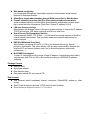
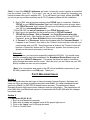
Panel – Wire Diagram
•
•
•
The modem should be connected to the router’s WAN port with an Ethernet cable(Cat
5/Cat 5e)
Power adapter should be connected to the power port on the router
Computers are to be connected to port 1-4 on the router (Typically with a straight
through cable Cat 5/Cat 5e)
7
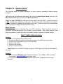
Chapter 2 - Quick install
The following steps are setup processes for most common broadband internet service
providers.
This section will be divided into three parts. Part one is for cable internet setup, part two is for
DSL internet setup and part three is for Macintosh Users.
*Note* the http://192.168.8.1 is the main console page for the EE-400R. Internet connection
is NOT required upon installation of this router. Any computer that is connected to the router’s
port 1-4 is capable of changing the settings on the router. It does not have to be a designated
port or computer to change the settings of the router.
Before you start
Make sure the internet connection from your ISP is working. Check to see if there is a
connection coming through your ISP (modem) to your computer. Also, check and see if the
lights are properly on when the router is connected with the computer(s) and the modem.
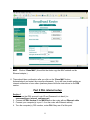
Part 1 Cable internet setup
Section 1
1. Turn off the cable modem and the router
2. Connect an Ethernet cable from the cable modem to the WAN port of the router
3. Connect your computers to ports 1-4 on the router
4. Power on the router
5. Power on the modem
6. Power on your computer
*Note* Make sure the WAN LED light and ports 1-4 LED lights are ON at the front panel of
the router.
Section 2
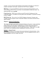
1. At the desktop (Windows based Operating System). Go to ‘Start’ > ‘Run’ and input
this address: http://192.168.8.1 and press ‘enter’
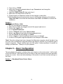
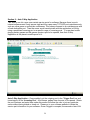
2. Your internet browser should automatically open up the ‘Broadband Router’ page
Example:
8
3. The password for the Administration Password is ‘admin’. It is case sensitive so
make sure the CAPS key is not on. Once ‘admin’ is entered, click on ‘Login’ to enter
the router’s configuration page.
*Note* Make sure the ‘WAN IP address’, ‘WAN Subnet Mask’, ‘WAN Gateway’, and ‘WAN
DNS’ are filled with numbers. This indicates that the router is communicating with the modem
(your ISP). If you are able to get those numbers, most likely you’re on the internet.
*Note* the next step is for those who can log onto the router page but cannot get an internet
connection through the ISP. (WAN IP addresses all show 0’s)
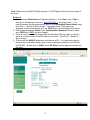
9
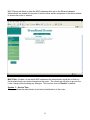
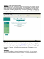
4. The page should look like this after you have logged onto the next page. The next step
is to click on the ‘Administration’ to the left side of the
screen.
10
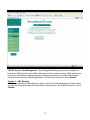
5. At the bottom of the ‘Administration’ section you should see a button says ‘Clone
MAC’. Click on ‘Clone MAC’ (this will let the router copy the MAC address on the
Ethernet adapter.)
6. There should be a confirmation after you click on the ‘Clone MAC’ button.
Acknowledge it and restart the computer afterwards. If you still have trouble getting an
internet connection or have other questions please follow the instructions in our FAQ
section.
Part 2 DSL internet setup
Section 1
1. Make sure that DSL account Login ID and Password is in hand (i.e.:
username@your_internet_company.net)
2. Connect the DSL modem to the WAN Port on the router with an Ethernet cable
3. Connect your computer(s) to port 1-4 on the router with Ethernet cable(s)
4. Turn the computer(s), DSL modem, router ON if they are off at this point
11
*Note* Make sure the WAN LED light and ports 1-4 LED lights are ON in the front panel of
the router.
Section 2
1. At the desktop (Windows based Operating System). Click ‘Start’ > go to ‘Run’ >
and type in this address in the box: http://192.168.8.1 and press ‘enter’. Your
internet browser should automatically open up the ‘Broadband Router Status’ page
(See Part 1 – Section 2 {2} for image). If the page shows ‘Page cannot be
displayed’ or blank then please go to our FAQ section for more helpful information.
2. Enter default password ‘admin’ in the ‘Administration Password’ column (make
sure CAPS key is OFF) and click ‘Login’
3. Once you have successfully logged onto the Broadband Router page, you should
see a list of various links on the left side of your screen. (See Part 1 – Section 2 –
{4} for image)
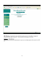
4. At this point the ‘WAN IP’ addresses should show all 0’s. It is usual and common
because the router hasn’t been setup to have a connection between your ISP and
the EE-400r. Please click on ‘WAN’ under ‘EZ Setup’ and the page should look like
this after:
12
*Note* In case if the WAN IP addresses are listed, it means the router is getting a connection
from the modem (your ISP). Try to see if you can go onto the internet by reopening your
internet browser and input a website URL. If you still cannot get online, please see FAQ. If
you do not get any numbers and they are all 0.0.0.0 please continue with the installation.
5. Most of DSL internet service providers have PPPoE type of connection. Bubble in
‘PPPoE’ as your ‘WAN Connection Type’ and it should bring down a longer menu
with ‘PPPoE Account’ that is where you input your full primary e-mail address from
your ISP (i.e. [email protected])
* Some DSL ISP use only a username as your PPPoE Account name
6. Next, type in the password for that e-mail account in ‘PPPoE Password’
7. ‘PPPoE Service Name’, ‘Dial on Demand’, and ‘Auto Disconnect when Idle’
should be left as is. After finishing the input on the ‘PPPoE Account’ and ‘PPPoE
Password’, press the ‘Save & Restart’ button for the changes to take effect.
8. A ‘Connect’ or a ‘Disconnect’ button should appear after the ‘Save and Restart’. If
it appears to be ‘Connect’, then click on the ‘Connect’ button and the router will try to
communicate with your ISP. Once the process is finished, the ‘Connect’ button will
become a ‘Disconnect’ button and if a ‘Disconnect’ appears, then it means you’re
already on the internet and ready to surf the net.
Aftermath
Congratulations, you have just successfully installed the EE-400r. You should notice
after the connection has been established, the ‘Broadband Router Status’ page will
display a list of ‘WAN IP Addresses’. This shows that there has been a connection
going through the modem and the router. After this point, you don’t have use your DSL
dial up software no more on your computer.
*Note* If no connections were made or the ISP did not establish a connection to your
EE-400r, please refer to our FAQ page. Thank you.
Part 3 Macintosh Users
Section 1
Since Macintosh uses the same type of internet browser (Internet Explorer, Netscape etc.),
users can follow the same procedures provided under Part 1 (for cable broadband internet
services) or Part 2 (for DSL/PPPoE based internet services). Some Macintosh based
Operating System might require some changes under its configuration. The steps below will
most likely allow your Macintosh system to communicate with the EE-400r after the changes
have been made.
Section 2
(For Macintosh OS 8.0 & 9.0)
1. Boot up your Macintosh computer
2. Make sure all cables are plugged in and all the proper lights are on
3. Click on the ‘Apple’ icon to bring up the menu
4. Click on ‘Control Panel’
13
5. Then click on ‘TCP/IP’
6. Make sure Ethernet is selected where it says ‘Connect as’ and change the
configuration to ‘DHCP’
7. Leave the ‘DHCP Client ID’ blank and close it
8. Make sure click Save button at the end
9. Please restart your Macintosh system for the changes to take effect
10. After the Mac is up and running, open up your web browser and type in this address:
‘http://192.168.8.1’ and follow the instructions under Part 1 and Part 2 to continue the
installation.
Section 3
(For Macintosh OS X or 10.00)
1. Boot up your Macintosh computer
2. Make sure all cables are plugged in and all the proper lights are on
3. Click on the ‘Apple’ icon
4. Go to ‘System Preference’
5. Click on ‘Network’ and choose ‘New Location’
6. Select your Ethernet card under the first configuration box
7. Pick the ‘TCP/IP’ tab and change it to ‘DHCP’
8. Click on ‘Apply’ to save the settings that you have just changed.
9. A reboot of the system might be required for the changes to take effect
*Note* Once the settings have been changed, the Macintosh computer should be able to log
onto the router’s configuration page and setup for the above 2 sections for your specific type of
internet connection. Please read through our FAQ guide if further assistance is needed on
setting up a Macintosh. Thank you for your patience.
Chapter 3 – Basic Configuration
The next chapter will explain in details of how each function on the router works. It will be split
a total of 5 sections. Each section will tell you some of the most common and some advanced
usages on a router. Users can take advantage of this section to suit their own best settings on
the router.
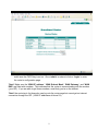
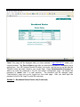
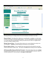
Section 1 – Broadband Router Device Status
14
*Note* this page will be displayed after you have entered: http://192.168.8.1 under your
internet browser. The ‘Device Status’ page tells you what are the current IP addresses you’re
getting from: Your ISP (Internet Service Provider), your router, and the last log on that was the
‘Refresh’ button will reset it back to your current login. Press ‘Administration Password’ is
where you enter the password to log into the router’s configuration page. By default the
password is ‘admin’ and it is case sensitive. The password can be changed under
‘Administration’ page once you’re logged into the router page. After you have input the
password, click on the ‘Login’ to enter the next page.
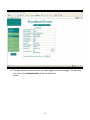
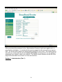
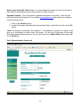
Section 2 – Broadband Router Device Info (Continued)
15
After you entered the password for the ‘Administration Password’ and have logged onto it, a
page like this will display. It is similar with the previous page but with more options to choose
from. On the left side is where you adjust/change settings for your router. The middle (Device
Info) tells you exactly what the current version of firmware is running and if you are getting IP
addresses from outside or within your network. The details of each selection on the left of the
page will be described as we move on to the next sections.
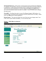
Section 3 - Administration (Part 1)
16
This page allows you to change some of the most commonly used items on a router.
Reset to Default – By clicking this it will give you a confirmation on whether or not the router
should be reset back to the factory default setting. If you have accidentally changed a setting
on a router and does not remember the setting you previously had, then it is suggested that
you click on ‘Reset to Default’ button.
Backup System Setting – This option allows storing your current settings by saving it onto
your hard-disk. It saves the current settings on the router to your computer.
Restore System Setting – User can obtain the router settings from here after the user has
saved the information on the router. This option can load previous settings from the hard-disk.
Old Password/New Password/Confirm Password – This section allows the user to change
the administration password on the router. A user can change the default password ‘admin’ to
a different password for security reasons. (Strongly recommended)
17
Auto Logout, when Idle Time is over: - You can change the amount of time for the router to
take before it automatically logs out itself if there is an idle occurred.
Upgrade Firmware – This is the place to update the firmware on the router. Once the user
has downloaded the firmware off of our website www.gigafast.com and saved onto a floppy or
a hard-disk (hard drive):
1. Click on the ‘Browse’ button
2. Locate the firmware (file) where the user stored (Floppy, hard-disk) and click on the ‘Go’
button.
*Note* this process should take a few moments. If the update is a success or a failure, it will
give you a confirmation on either one of the events. Do not turn off the power of the router
during the update firmware process. If a user gets such error “Update failed” then please refer
to our FAQ guide.
Part 2 (Administration Continued)
18
View System Event Log – Allows users to view the most recent events that have happened.
For example, each time when a user logs onto the ISP (Internet Service Provider) it will record
it under the log. It will be erased every time the router is unplugged, and plugged back in.
This function provides administrator a convenient diagnostic method for troubleshooting. It
also records the detailed intruder information for analysis. Press REFRESH button to display
the latest events.
Clone MAC – This allows the router to a copy of the Ethernet adapter’s MAC address. It is
used only when a user have trouble connecting to the ISP (Internet Service Provider). Please
refer to our FAQ guide for further explanation.
Restart System – This option will refresh the router if there were any changes made. Force
router to do a system restart immediately. It is not commonly used.
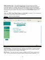
Section 4 – WAN (Wide Area Network)
19
WAN Connection Type – This section allows the user to set the proper type of WAN
connection is being used. By default the ‘DHCP Client’ is bubbled. Each type will give you
some other options. For example: After the ‘PPPoE’ is bubbled, it will give you extended
options like: PPPoE Account, PPPoE Password to fill out (Read Chapter 2_Part 2_Section 2)
Once the settings are provided, make sure you click on the ‘Save & Restart’ button for it to
take effect.
*Note* the ‘DHCP Client Domain Name’ and ‘Host name’ is optional. It is not commonly
used so users can avoid this unless the ISP demands it.
Section 5 – LAN (Local Area Network)
LAN IP Address – This shows the current IP address on the LAN side. If a user is running a
static IP and cannot log onto the router page, then changing the LAN IP Address might be
needed. By default the LAN IP Address is 192.168.8.1
DHCP Server – This allows the user to enable or disable the DHCP Server running on the
router. It is not recommended to change this feature unless the network demands it. For
20
example: If you’re running a static IP address on the network and DHCP is not allowed or
needed, then disable it as needed. By default the DHCP Server is enabled.
DNS Proxy – If a user has a DNS Proxy that was set previously and would like to use it
without having conflicts with the router, then it is recommended to disable this feature. By
default the DNS Proxy is enabled.
IP pool from & to – DHCP server will offer unused IP from the IP address pool to the
requesting computer. End address must be greater then initial address. By default the range
is set at: 17~128
DHCP Client List – This is a list of your DHCP IP address information. Example: what
computer at which computer’s name on what MAC address of the network card did receive
what IP address.
Chapter 4 – Advanced Configuration
This chapter will explain great details of advanced settings on the router. A user can change
these settings for their own needs and purposes or to fix some of the commonly known
problems out there in the industry. It will be divided into total of 10 sections and it is
recommended and accessible for both home and business users. Please refer to our FAQ
guide if there is an unexplained question regarding the functions on the router.
Section 1 – Access Control
Access Control allows you to set some of the security features for the administrator. It also
gives the ability to access from outside to the router. Once the changes are made, click on
‘Save & Restart’ to have the changes take effect.
21
Response to Ping from WAN – If this option is allowed, others can do a direct ping to the
router from outside of your network. Due to security reasons this option is set to ‘Deny’ by
default.
Web Management from WAN – Enable administrator to log in and configure the router
remotely from internet. It is set to ‘Deny’ by default.
Example: http://yourwanip:54321
Block Client in LAN – You can block certain internet protocols (IP’s) within your own
network and disallow other clients or computers to access other pages within the network. It is
set at ‘Disable’ by default.
Filter Packets from LAN – This option allows the administrator to block certain ports on the
router so other clients can’t access them.
Section 2 – MAC Filter
22
MAC Filtering will block or allow the MAC addresses that are on the Ethernet adapters.
Administrator can enable this function to block or allow certain computers or the entire network
to access the router or network.
MAC Filter – Enable it to set which MAC addresses the administrator would like to block so
the blocked clients can’t make changes on the router. The clients are still able to get onto the
router, though without making any changes. This function is set at ‘Disable’ by default.
Section 3 – Service Time
This page allows the administrator to set a time limit/duration of the router.
23
Service Time Allocation – Administrator can now apply a limit on all the clients or computers
that are connected to the router. For example: If it is set from 9:00AM~12:00PM that means
the clients can only log onto the WAN/LAN from between those times. Administrator can
choose either by continuous usage time or by time zone. This option is set at ‘Normal’ by
default which means the connection is always allowed.
Section 4 – LAN PC Management
Similar to ‘Service time Allocation’ but instead of changing the time, the administrator can
block the access based on the ‘Computer Names’ and ‘MAC Addresses’
24
LAN PC Service Time Management – By allowing/disallowing any particular computers to
browse the WAN based on their MAC addresses and the computer names. MAC address can
be found on the Ethernet adapters and the computer names are found under ‘My Computer’
under Microsoft Windows Operating Systems. By default this function is set at ‘Disable’.
Section 5 – URL Blocking
URL Blocking allows the administrator to block certain URL (web addresses) so clients cannot
log onto the designated pages that administrator have blocked. By default this option is set at
‘Disable’.
25
URL Blocking – Administrator can enable this function and put in the URL of a page and
clients will not be able to log onto it. User can block all the way up to 8 URLs.
Section 6 – Virtual Server
Virtual Server can allow the administrator to open one or multiple ports on the router for a LAN
PC.
26
Virtual Server - If the user has a server behind the route he/she can open a particular port or
ports to allow incoming and outgoing traffic through the router. This function is mainly for
computers that are on the network. By default this setting is set at ‘Disable’ if you have trouble
opening ports please read our FAQ section to understand more about Virtual Server.
Section 7 – DMZ
DMZ (De Militarized Zone) allows the port on your computer to be seen outside of your
network. It basically allows you to be shown on the WAN side. This function is mostly used for
game or program specific purposes. In comparison with the virtual server, DMZ is not
protected by firewall. Enable DMZ host are dangerous and subject to be attacked/accessed by
internet intruder/hacker. However DMZ host is able to gain full access privilege right to
internet.
27
A. The Host DMZ – Enable it and input the last digit of your current IP address and it will
open up you to the WAN side. For example: 192.168.8.XX The XX marks the last
digits from the IP address you’re getting on that computer. If your IP address ends with
17, then put 17 in the empty box and click on ‘Save & Restart’. Some users might have
trouble getting the router to communicate with their game console servers (i.e.
PlayStation2 by Sony or Xbox by Microsoft) and if that is the case then enable DMZ and
it should allow you to enter the server after save & restart.
B. Multiple DMZ host – You can enable the Multiple DMZ host function, only when your
current WAN connection is STATIC. This router allows 8 LAN PC at most in LAN to
become DMZ hosts. The mechanism of multiple DMZ host is based on the mapping
relation between WAN STATIC IP and LAN IP. These DMZ host IP will skip NAT port
translation to gain unrestricted 2-way communication capability.
28
Section 8 – Auto 2-Way Application
This section can let a user open certain service ports for software. Because there is much
internet software need 2-way access right and they open many TCP/UDP ports simultaneously
such as online game or audio/video conference. They always connect to an outside server with
a fixed destination port. Then the server would communicate with the application in LAN by
using a predefined incoming port or a specific range of incoming ports. If a user has trouble
playing certain games and the games require a port to be opened, then Auto 2-Way
Application is the place to enable ports for it.
Auto 2-Way Application – Once enabled, put the outgoing port in the ‘Trigger Port’ box and
incoming port in the ‘Incoming Port’. All software, games have its ports to be opened. Obtain
the port numbers and enter them under this section will allow the user to join any particular
server without being kicked or timed out. Please go to your software website to obtain the
service port information for your software. Once a trigger is occupied, the second or later LAN
29
PC should not use that trigger port until the first LAN PC has released it. Release means that
the first PC doesn’t use that trigger port for more then 5-6 minutes. By default this option is set
at ‘Disable’.
Section 9 – Dynamic DNS
This option will automatically translate your domain name to your WAN IP address for others to
access your page.
Dynamic DNS – If you don’t have a domain name and a host setup then others will require a
Dynamic DNS to log onto your webpage. This enables others to see you on the WAN side and
allows them to browse your own page. Often the server will automatically update your WAN IP
address, therefore the Dynamic DNS function allow the update to be saved so others can still
browse your page without the changes to be made manually. For further information please
visit: www.DynDNS.org and by default this function is set at ‘Disable’.
30
Section 10 – UPnP (Universal Plug & Play)
“Universal Plug and Play”, is designed to support zero-configuration and automatic discovery
device categories from a wide range of vendors. With UPnP enabled, the internet Gateway
Device (IGD) could be discovered and detected by UPnP capable PCs. Thus IGD devices
could be easily managed by windows system. It recognizes a hardware be plugged into the
router and function as one. This function will only work under Microsoft Windows ME & XP
based Operating Systems.
UPnP – Once it is enabled, this function will allow the software on the hardware device to have
a time limit before it’s recognized as a device. Basically this allows the Windows ME/XP to
access the router’s configuration page (http://192.168.8.1) through ‘Network Neighborhood’
You can change the value by putting in a different number as long as it’s between 30~1800
seconds (or 30 minutes). This function is not commonly used, so by default it is set at
‘Disable’.
Conclusion
This concludes the Basic & Advance Configuration for the EE-400r. The most common
questions are answered based on these two chapters. If you need further assistance or
31
perhaps require more information then please visit our FAQ guide or contact one of our lines
listed below.
Tech Support: [email protected] or 1(888)433-6788
RMA/Replacement: [email protected] or 1(866)964-2970
Customer Service: [email protected]
Thank you for choosing GigaFast
32
Chapter 5 – Frequently Asked Questions (FAQ)
Still having trouble setting up this router? Please read the following questions and answers to
solve your problems with the router.
Q: I can’t seem to log onto the ‘Broadband Router Configuration’ page
(http://192.168.8.1)
A: If you have already followed the instructions from the manual and still can’t log onto it:
1. Please do a power reset on the router. For example: Turn the router off for few
minutes and turn it back on.
2. Use a paper-clip or a pin to do hardware reset the router. On the router there should be
a pin sized hole and that is where you insert the pin. Once the pin is inserted, hold it
down for 5 seconds and you should see the lights on the router flash for a moment.
3. Try to ping http://192.168.8.1 if you can receive an IP but can’t ping the router that
means the router might be defective. Perhaps try another cable or different port on the
router.
4. Make sure you have the same subnet mask between the computers and the router.
5. If you did a ping on the router and gets a reply like 169.xx.xx.xx, that means the
Ethernet cable might be bad (or check your Ethernet card for proper installation).
Q: I have followed the ‘Quick Install’ but still can’t get my router to work
with my Internet Service Provider.
A: Check the following:
1. Make sure the Ethernet cable is working.
2. Make sure the lights on the router are flashing (this indicates that there is traffic coming
and going from the router to the modem).
3. See if the network adapter was installed properly and inserted into the slot on the
motherboard correctly.
4. Confirm there is internet connection (WAN Connection) coming in from your ISP (or the
modem).
5. Double check the WAN IP addresses on the router. If the WAN IP addresses are
shown but can’t connect, that means the source is being blocked from the operating
system by software or perhaps hardware. Occasionally the anti-virus or firewall
programs might stop an IP from coming in and going out of the network. Disable the
software if you have one and try again.
*Note* if you’re not getting the router’s IP or a WAN IP address after you plug the cables into
the router and to the computer, then do an IP release and renew. To do this:
33
(For Windows 95, 98, ME)
1. Go to ‘Start’ > ‘Run’ and type in: ‘winipcfg’ and press ‘Enter’ or click ‘Ok’
2. It should bring a dialog up and give you a list of network adapters you have on that
system you’re using.
3. Select the Ethernet adapter that is connected to the router and click on ‘Release All’
(this should take few moments and upon completion it’ll give you all 0’s).
4. After the IP has been released, click on ‘Renew All’ (this will refresh the IP addresses
on the computer).
5. If the IP address says: 192.168.8.XX then that means there is a connection between
the modem and the router.
(For Windows 2000, XP)
1.
2.
3.
4.
5.
Go to ‘Start’ > ‘Run’ and type in: ‘command’ and press ‘Enter’ or click ‘Ok’
This should bring up your MS-DOS Prompt
At the prompt, type in the following: ipconfig /release and press ‘Enter’
After the process has finished, type in: ipconfig /renew and pres ‘Enter’
This will refresh your IP addresses
To do a proper power-cycle/reset on the router, modem, computer:
1.
2.
3.
4.
Turn the devices listed above off
Turn the router back on after few minutes
Turn the modem back on after few minutes
Use a paper-clip or pin and reset the router. Insert the pin and hold down the button for
five seconds
5. Turn back on the computer(s) and see if you can go online
Q: Does the router come with firewall protection?
A: Yes, a built-in hardware firewall is placed inside of the router. It protects intruders hackers
from vandalize your information.
Q: Can I turn the firewall function off?
A: You can’t turn the firewall off, but you can make yourself seen on the WAN side. To do this,
just enable ‘DMZ’ and that should allow others to see you or your server.
Q: Everything works great on the router, but for some reason the router
keeps dropping my connection once in a while.
A: If that is the case, please update the firmware on the router to the latest version available
on our website: www.gigafast.com and go to support then choose the proper model number
34
(EE-400r) to download the firmware for the router. If this still doesn’t solve the problem then
please contact our tech support line.
Q: I’m trying to play games online with the router, but it won’t let me.
A: Try to enable ‘DMZ’ and see if that helps. Put the last two digits of your current IP
Addresses into the empty box under DMZ and click on ‘Save & Restart’ Restart the computer
afterwards. If DMZ does not help that means the game server might need you to open some
ports for the router to play. Get the port numbers and go to Part 2 of this FAQ to find out more
information on how to fix this issue.
Q: I have a Motorola Surf Board Series modem and after I plugged the
cable from the modem to the router’s WAN port, the WAN light doesn’t
seem to light up and can’t log onto the internet.
A: Unfortunately the Motorola Surf Board Series modem (3100, 4100, 4200 etc.) is not
compatible with our router until you upload the WAN fix for the router. Please go to our
website: www.gigafast.com or send us an e-mail regard this problem and we will send you a
copy of the WAN fix immediately.
Q: Does the router work with AOL Broadband Internet Service?
A: Unfortunately AOL (America Online) uses a different Proxy setting. It requires upon log on
and the router can’t bypass that. We might have a firmware update for this issue later in the
future.
Q: Is there a way to boost my internet connection to have a faster
download/upload speed with this router?
A: A router does not provide the bandwidth from your ISP. Your ISP decides how much
bandwidth to be produced and sent in and out of their servers. Disabling the anti-virus
program or third party firewall programs might help a little bit, but it is up to personal
preferences.
Q: I have two computers or more and one of them is able to go online but
the other one says “IP Conflict” or just can’t go online?
A: If you have an IP conflict within the network, do an IP release and renew then restart the
computers to see if that helps. If only one of the computers does not work, then do the IP
release and renew on that particular computer. If none of it helps, turn the router off and turn it
back on after few minutes. If problem still exists, update the firmware on the router.
35
Q: I have tried to update the firmware on the router but it keeps telling me
“Update Failed”
A: You might have downloaded or received the wrong firmware. Check the bottom of the
router and look for a serial number (it usually starts with an ‘A’ or a ‘B’). Then send us an email and we will send you the correct firmware. If you are a MAC user, please always use IE
browser to do the firmware update. If you have a OS/X, you can also use SAFRI browser to
do so.
Q: My router allows me to send e-mails out but doesn’t allow me to receive
e-mails or the other way around, why?
A: This usually happens when the MTU (Maximum Transfer Unit) on the router is different
than the one your ISP provided. Please contact your ISP and get the correct value of the MTU
and upgrade the firmware afterwards. Once the firmware is updated:
1. Go to the router’s configuration page (http://192.168.8.1)
2. Once you’re there, log in with the administrator password (‘admin by default)
3. After you have logged in, type mtu.cgi at the end of the address. It should look like
this: http://192.168.8.1/mtu.cgi (* require firmware v1.52 and up)
4. Once you have successfully logged onto the MTU setup page, input the MTU values
your ISP have provided you and click on ‘Save & Restart
Q: The router and computers works fine, but for some reason when it tries
to load web pages it would take a long time before it completes?
A: Try to update the firmware on the router first. Check and see if there is third party program
running in the background that is eating up your resources. Also, check and see if the router is
overheating or hotter than usual. It is better not to have the router on the carpet floor or inside
of none air-flowing environment.
Q: My router was working fine for a while and all of sudden it stopped
working, what should I do?
A: If you have moved to a different place or perhaps changed to a different ISP, try the ‘Quick
Install’ and see if that helps. If the lights on the router went out and doesn’t flash anymore then
most likely the router might be defective.
Q: How do I setup a VPN (Virtual Private Network) PPtP?
A: Please note that this router supports only PPtP Packet Pass-Through. First you need to
understand that there are three protocols of VPN software. They are the following:
1. PPtP (Point to Point Tunnel Protocol) Æ supported
2. L2tP (Layer 2 Tunnel Protocol) Æ not supported
36
3. IPSEC (Internet Protocol Security) Æ not supported
The router itself does not have a VPN function. It is allowed PPtP Packet Pass-Through
once the router has updated the firmware to version 1.91 or above. To setup a PPtP
Packet Pass-Through on the router, please go to:
1. Virtual Server under the router’s configuration page.
2. Open service port 1723 for your VPN server (IP address).
3. Click on ‘Save & Restart’ to take effect.
The steps above will allow the packets to pass through. Reason for this is because if this
function is not enabled, the router will automatically block the packets that are coming and out
of the router.
Q: I have several static IP addresses and would like to run them with my
router, how can I do that?
A: First off you have to go to the router’s configuration page (http://192.168.8.1):
1. Go to ‘WAN’ section under easy setup on the router page and bubble in ‘Static IP’
2. Input one of your static IP address in the box and click on ‘Save & Restart’
3. Go to DMZ section, you can enable up to 8 static IP address at one time
37
Appendix A : Cabling and Pin Assignment
A-1 RJ-45
There are different grades, or categories, of twisted-pair cabling. Category 5 is the most reliable and is highly
recommended. Category 3 is a good second choice. Straight-through cables are used for connecting
computers’ NIC cards to a hub. Crossover cables are used for connecting a hub to another hub. (The router
provides a built-in uplink/normal switch. Uplink mode is crossed internally, which allows you to link or connect
hubs together with a straight-through cable instead.)
A-1-1 RJ-45 pin assignment
There are 8 thin, color-coded wires inside, run from one end of the cable to the other. All 8 wires are
used.
Table A-1
Wire 1
Wire 2
Wire 3
Wire 4
Wire 5
Wire 6
Wire 7
Wire 8
RJ-45 Color Chart
White with an Orange stripe
Orange
White with a Green Stripe
Blue
White with a Blue Stripe
Green
White with a Brown Stripe
Brown
Pin 1
*Note* To determine which wire is wire number 1, hold the cable so that the end of the plastic
RJ-45 tip (the part that goes into a wall jack first) is facing away from you. Face the clip down so
that the copper side faces up (the springy clip will now be facing the floor), when looking down
on the copper side, wire 1 is on the far left.
Connection between NIC card and Hub
In a straight-through cable, wire 1, 2, 3, and 6 at one end of the cable are the same as wires 1, 2, 3, and
6 at the other end. The straight through cable is used to connect the NIC card and the hub.
Table A-2
Wire
1
2
3
6
Straight Through Cabling
Becomes
1
2
3
6
38
Connection between Hub and Hub
In a crossover cable, the orders of the wires change from one end to the other. Wire 1 becomes 3, and
2 becomes 6. The crossover cable is used in connecting hubs directly.
Table A-3
Crossover Cabling
Wire
1
2
3
6
Becomes
3
6
1
2
39
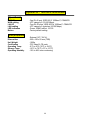
Appendix B – Technical Information
Operational
WAN I/F
WAN cabling
LAN I/F
LAN cabling
LED indication
Button
: One RJ-45 port, IEEE 802.3 100BaseT, CSMA/CD
: UTP category 5 (10/100 Mbps).
: Four RJ-45 ports, IEEE 802.3u 100BaseT, CSMA/CD
: UTP category 5 (switched 10/100 Mbps).
: Power, WAN Link/Act, 10/100
: Factory default setting.
Environmental
Power Input
Dimensions
Unit Weight
Certification
Operating Temp
Storage Temp
Operating Humidity
: External, DC 7.5V/1A.
: 255 x 185 x 93 mm (TBD)
: 1050g
: FCC class B, CE mark
: 0°C to 40°C (32°F to 104°F)
: -20°C to 70°C (-4°F to 157°F)
: 10% to 85% non-condensing
40