1
TECHNICAL MANU
AL
MANUAL
TM
ACVC9/AMVC95
GCVC9/GMVC95
90% UP TO 96% Gas Furnace Units
• Refer to Service Manual RS6612002 for troubleshooting information.
• Refer to the appropriate Parts Catalog for part number information.
• Models listed on page 3.
This manual is to be used by qualified, professionally trained HVAC technicians only. Goodman does
not assume any responsibility for property damage or personal injury due to improper service
procedures performed by an unqualified person.
®
®
is a registered trademark of Maytag Corporation or its related companies and is used under license to
Goodman Company, L.P., Houston, TX. All rights reserved.
Copyright ©2012-2013 Goodman Company, L.P.
RT6612025r5
November 2013
PRODUCT IDENTIFICATION
The model and manufacturing number are used for positive identification of component parts used in manufacturing.
Please use these numbers when requesting service or parts information.
G
C
V
C
PRODUCT
TYPE:
G: Goodman®
A: Amana®
Brand Gas
9
070
4
C
A
ADDITIONAL
FEATURES:
N: Natural Gas
X: Low NOx
AFUE
9: 90%
95: 95%
SUPPLY TYPE:
C: Counterflow/
Horizontal
M: Upflow/
Horizontal
X
COMMUNICATION
FEATURE:
C: 4-wire
Communication
Ready
CABINET
WIDTH:
B: 17-1/2"
C: 21"
D: 24-1/2"
A
MINOR
REVISION
LEVEL
A: Initial Release
MAJOR
REVISION
LEVEL
A: Initial Release
AIRFLOW
CAPABILITY:
3: 1200
4: 1600
5: 2000
FURNACE TYPE:
V: Variable Speed
NOMINAL INPUT:
045: 45,000 Btuh
070: 70,000 Btuh
071: 70,000 Btuh
090: 90,000 Btuh
091: 90,000 Btuh
115: 115,000 Btuh
WARNING
HIGH VOLTAGE!
Disconnect ALL power before servicing or installing this unit. Multiple power
sources may be present. Failure to do so may cause property damage, personal
injury or death.
Goodman will not be responsible
for any injury or property damage
arising from improper service or
service procedures. If you install or perform service on
this unit, you assume responsibility for any personal
injury or property damage which may result. Many jurisdictions require a license to install or service heating
and air conditioning equipment.
WARNING
2
Installation and repair of this unit
should be performed ONLY by individuals meeting the requirements of an "entry level technician", at a minimum, as specified by the Air-Conditioning,
Heating, and Refrigeration Institute (AHRI). Attempting to
install or repair this unit without such background may
result in product damage, personal injury or death.
WARNING
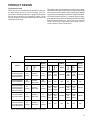
PRODUCT IDENTIFICATION
The model and manufacturing number are used for positive identification of component parts used in manufacturing.
Please use these numbers when requesting service or parts information.
ACVC950714CXAD
ACVC950915DXAD
ACVC950714CXBA
ACVC950915DXBA
ACVC951155DXAA
GCVC951155DXAE
GCVC950714CXAD
GCVC950915DXAD
GCVC950714CXBA
GCVC950915DXBA
GMVC950453BXAE
GMVC950704CXAE
GMVC950905CXAD
GMVC950905DXAE
GMVC951155DXAE
GMVC950453BXBA
GMVC950704CXBA
GMVC950905CXBA
GMVC950905DXBA
GMVC951155DXBA
AMVC950453BXAE
AMVC950704CXAE
AMVC950905CXAD
AMVC950905DXAE
AMVC951155DXAE
AMVC950453BXBA
AMVC950704CXBA
AMVC950905CXBA
AMVC950905DXBA
AMVC951155DXBA
Earlier revisions of these units can be found in RT6612021*
WARNING
The United States Environmental Protection Agency (“EPA”) has issued various regulations regarding the introduction and disposal of refrigerants introduced into this unit. Failure to follow
these regulations may harm the environment and can lead to the imposition of substantial fines.
These regulations may vary by jurisdiction. Should questions arise, contact your local EPA office.
Do not connect or use any device
that is not design certified by
Goodman for use with this unit.
Serious property damage, personal injury, reduced unit
performance and/or hazardous conditions may result
from the use of such non-approved devices.
WARNING
To prevent the risk of property
damage, personal injury, or death,
do not store combustible materials or use gasoline or
other flammable liquids or vapors in the vicinity of this
appliance.
WARNING
3
PRODUCT DESIGN
General Operation
Models covered by this manual come with a new 4-wire communicating PCB. When paired with a compatible communicating indoor unit and a CTK0* communicating thermostat,
these models can support 4-wire communication protocol
and provide more troubleshooting information. These models are also backward compatible with the legacy thermostat wiring.
Notes:
The GCVC9, GCVC95, GMVC95, AMVC95 and ACVC95
furnaces are equipped with an electronic ignition device to
light the burners and an induced draft blower to exhaust
combustion products.
2. Line voltage wiring can enter through the right or left side
of the furnace. Low voltage wiring can enter through the
right or left side of furnace.
An interlock switch prevents furnace operation if the blower
door is not in place. Keep the blower access doors in place
except for inspection and maintenance.
These furnaces are also equipped with a self-diagnosing electronic control module. In the event a furnace component is
not operating properly, the control module's dual 7-segment
LED's will display an alpha-numeric code, depending upon
the problem encountered.
For information regarding diagnostics and LED codes refer
to the Installation Instructions shipped with the furnace or
the service manual .PDF available at www.goodmanmfg.com
or www.amana-hac.com.
The rated heating capacity of the furnace should be greater
than or equal to the total heat loss of the area to be heated.
The total heat loss should be calculated by an approved
method or in accordance with “ASHRAE Guide” or “Manual
J-Load Calculations” published by the Air Conditioning Contractors of America.
1. Installer must supply one or two PVC pipes: one for combustion air (optional) and one for the flue outlet (required).
Vent pipe must be either 2” or 3” in diameter, depending
upon furnace input, number of elbows, length of run and
installation (1 or 2 pipes). The optional Combustion Air
Pipe is dependent on installation/code requirements and
must be 2” or 3” diameter PVC.
3. Conversion kits for propane gas and high altitude natural
and propane gas operation are available. See High Altitude Derate chart for details.
4. Installer must supply the following gas line fittings, depending on which entrance is used:
Left -- Two 90° Elbows, one close nipple, straight pipe
Right -- Straight pipe to reach gas valve.
Accessibility Clearances (Minimum)
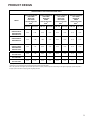
*MVC95* MINIMUM CLEARANCES TO COMBUSTIBLE MATERIALS
(INCHES)
POSITION* FRONT
The furnace should be as centralized as is practical
with respect to the air distribution system.
•
Do not install the furnace directly on carpeting, tile, or
combustible material other than wood flooring.
•
When suspending the furnace from rafters or joists,
use 3/8" threaded rod and 2” x 2” x 1/8” angle as
shown in the Installation and Service Instructions. The
length of the rod will depend on the application and
clearance necessary.
•
FLUE
FLOOR
3
0
0
1
0
C
Alcove
6
0
4
0
C
*=
All positioning is determined as installed unit is viewed from the front.
C= If placed on combustible floor, floor MUST be wood only.
NC= For instalaltion on non-combustible floors only. A combustible
subbase must be used for installations on combustible flooring.
*CVC9 MINIMUM CLEARANCES TO COMBUSTIBLE MATERIALS
(INCHES)
POSITION* FRONT
SIDES
REAR
TOP
FLUE
FLOOR
Upflow
1
0
0
1
0
NC
Horizontal
Alcove
6
0
4
0
C
*=
All positioning is determined as installed unit is viewed from the front.
C= If placed on combustible floor, floor MUST be wood only.
NC= For instalaltion on non-combustible floors only. A combustible
subbase must be used for installations on combustible flooring.
Alcove Illustration
REAR
SIDE
When installed in a residential garage, the furnace
must be positioned so the burners and ignition source
are located not less than 18 inches (457 mm) above
the floor and protected from physical damage by vehicles.
TOP
Upflow
SIDE
•
REAR
Horizontal
*Obtain from: American National Standards Institute 1430
Broadway New York, NY 10018
Location Considerations
SIDES
ALCOVE
24" at front is required for servicing or cleaning.
Note: In all cases accessibility clearance shall take
precedence over clearances from the enclosure where
accessibility clearances are greater. All dimensions are
given in inches.
4
PRODUCT DESIGN
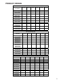
High Altitude Derate
When this furnace is installed at high altitude, the appropriate High Altitude orifice kit must be installed. This is required due to the natural reduction in the density of both the
gas fuel and combustion air as altitude increases. The kit
will provide the proper design certified input rate within the
specified altitude range.
High altitude kits are purchased according to the installation altitude and usage of either natural or propane gas. Refer
to the chart below for a tabular listing of appropriate altitude
ranges and corresponding manufacturer’s high altitude Natural Gas and Propane Gas kits. For a tabular listing of appropriate altitude ranges and corresponding manufacturer's High
Altitude Pressure Switch kits, refer to either the Pressure
Switch Trip Points & Usage Chart in this manual or the Accessory Charts in Service Instructions.
"STANDARD" and "HIGH ALTITUDE" KITS
0 - 7,000 Feet (Sta ndard Altitude)
Gas Orifices
1
ID Blwr
Pres sure
Switch
Gas Orifices
ID Blwr
Pressure
Switch
No
Change
GMVC95 0905CX*
AMVC950905CX*
No
Change
LPM-06*
#55 Orifice
(1)
No
Change
GMVC95 0905DX*
GMVC95 1155DX*
AMVC950905DX*
AMVC951155DX*
No
Change
LPM-06* (1)
#55 Orifice
No
Change
HANG13 HALP11
# 56
#44
Orifice Orifice
HAPS29
HANG14 HALP11
#56
#45
Orifice Orifice
HAPS29
GCVC91 155DX*
ACVC95 1155DX*
No
Change
LPM-06*
#55 Orifice
(1)
No
Change
HANG13 HALP11
#44
# 56
Orifice Orifice
HAPS29
HANG14 HALP11
#45
#56
Orifice Orifice
HAPS31
GCVC950714CX*
GCVC950915DX*
ACVC95 0714CX*
ACVC95 0915DX*
No
Change
LPM-06*
#55 Orifice
(1)
No
Change
(1)
HANG13 HALP11
# 56
#44
Orifice Orifice
N/A
N/A
N/A
N/A
HAPS28
N/A
N/A
Propan
e
LPM-06*
#55 Orifice
Natural
No
Change
Propan
e
GMVC950453BX*
GMVC95 0704CX*
AMVC950453BX*
AMVC950704CX*
Natural
Propan
e
Gas Orifices
9,001 - 11,000 Feet
Natural
Furnace
ID Blwr
Pressure
Switch
7,001 - 9,000 Feet
HANG14 HALP11
#56
#45
Orifice Orifice
N/A
N/A
N/A
N/A
HAPS28
N/A
N/A
LPM-06* supports Honeywell and White-Rodgers 2-stage valves
5
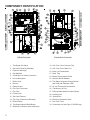
COMPONENT IDENTIFICATION
NOTICE
Ho rizonta l Conn ect ions- Lef t Si de
Ho rizont al Co n ect ions- Ri ght S id e
0140F00 821
NOTICE
Thi sf i t t ni g si sp ec i al l yd esig n ed t o
d rai nw a t e r f r m
o t he f ul e asse mb l y
Ho ri zon
tal Conn ecti ons-Left Sid e
Ho rz
i ontal Conn ecti o
ns-R g
i ht Si de
0140
F 00821
E
C
Upflow/Horizontal
1 Two-Stage Gas Valve
18 Coil Front Cover Pressure Tap
2 Gas Line Entrance (Alternate)
19 Coil Front Cover Drain Port
3 Pressure Switch(es)
20 Drain Line Penetrations
4 Gas Manifold
21 Drain Trap
5 Combustion Air Intake Connection
22 Blower Door Interlock Switch
6 Hot Surface Igniter
23 Inductor (Not All Models)
7 Rollout Limit
24 Two-Stage Integrated Control Module
8 Burners
9 Flame Sensor
(with fuse and diagnostic LED)
25 24 Volt Thermostat Connections
10 Flue Pipe Connection
26 Transformer (40 VA)
11 Flue Pipe
27 ECM Variable Speed Circulator Blower
12 Primary Limit
28 Auxiliary Limit
13 Gas Line Entrance
29 Junction Box
14 Flue Pipe Connection (Alternate)
30 Electrical Connection Inlets
15 Rubber Elbow
31 Coil Front Cover
16 Two-Speed Induced Draft Blower
32 Combustion Air Inlet Pipe (*CVC9/95 only)
17 Electrical Connection Inlets (Alternate)
6
Counterflow /Horizontal
1"
Ù®ÄdÙÖ
ϳдΗ
17 1/2
21
24 1/2
0453BX*
0704CX*
0905CX*
0905DX*
1155DX*
SMALL
MEDIUM
LARGE
A
UNITS
CABINET
SIZE
E
D
FRONT VIEW
D
Bottom Knock-Out
&ʽ&½Ä¦Ý
LEFT SIDE VIEW
40"
;®Ý«Ù¦Ϳ
hĥʽ&½Ä¦Ý
11¾"
30¼"
21¼"
ϭϵϹШІЋ"
ϮзΗ
1¾"
¾"
2½"
®Ù/Äã»W®Ö
ϮΗWs
ϮϯϿШІЋΗ
hĥʽ&½Ä¦Ý
&ʽ&½Ä¦Ý
Bottom
Knock-Out
ϮϮЩІЋΗ
>ÊóͲsʽã¦
½ãÙ®½Kçã½ã 1¾"
^®çãͲKçã
23"
>¥ãͲ^®Ù®Ä>®Ä
,®¦«Ͳsʽã¦
½ãÙ®½Kçã½ã
½ãÙÄã'Ý
^çÖÖ½ù
ϭϵиΗ
D
20 3/8
16 3/8
12 3/8
C
ϯϮϷϹШІЋΗ
D
11¾"
ϭϵϹШІЋΗ
ϮзΗ
18 5/8
14 5/8
12 5/8
30¼"
ϮϳЯΗ
ϮϰϿШІЋΗ
ϰЯΗ
ϮϷϷШІЋΗ
sÄãͬ&½çW®Ö
ϮΗWs
All dim ensions are in inches.
23
19
15
B
ϭϲзΗ
2"
ÊÄÄÝã
Ù®ÄãÙÖ
óͬвΗWs
®Ý«Ù¦
;Ù®¦«ãÊÙ
½¥ãÝ®Ϳ
¾"
ϮЩІЋΗ
>ÊóͲsʽã¦
½ãÙ®½Kçã½ã
RIGHT SIDE VIEW
1¾"
^®çãͲKçã
dÙÖ
,®¦«Ͳsʽã¦
½ãÙ®½Kçã½ã
Z®¦«ãͲ^®
Ù®Ä
Ù®Ä>®Ä
ϲЯΗ
®Ù
®Ý«Ù¦
½ãÙÄã®Ù
/Äã»>Êã®ÊÄ
^ãÄÙ'Ý^çÖÖ½ù
½ãÙÄãsÄãͬ
&½ç>Êã®ÊÄ
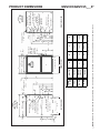
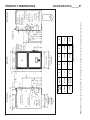
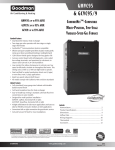
NOTE: Airflow area will be reduced by approximately 18% if duct flanges are not unfolded. This could cause performance issues and noise issues.
ϭзΗ
14"
1½"
¾"
28¾"
®Ù
®Ý«Ù¦
PRODUCT DIMENSIONS
GMVC95/AMVC95___X*
7
8
®Ù
®Ý«Ù¦
hĥʽ&½Ä¦Ý
ϮϬϻШЈЇΗ
&ʽ&½Ä¦Ý
ϭϴзΗ
>¥ãͲ^®
Ù®Ä>®Ä
^ãÄÙ
'Ý^çÖÖ½ù
Ù®ÄdÙÖ
,®¦«Ͳsʽã¦
½ãÙ®½Kçã½ã
>ÊóͲsʽã¦
½ãÙ®½Kçã½ã
20¼"
21
24 1/2
0714CX*
0915DX*
1155DX*
MEDIUM
LARGE
A
40"
UNITS
11½"
ϵϷϹШІЋΗ
ϭϱЪΗ
ϮϴϻШІЋΗ
¾"
CABINET
SIZE
ϰЯΗ
ϮзΗ
1¾"
2½"
®Ù/Äã»W®Ö
ϮΗWs
23
19
B
18 5/8
14 5/8
D
2"
8¼"
20 7/8
17 1/2
E
ϭϭзΗ
9¾"
14"
ϭϴϷϹШІЋΗ
ϮϷϷШІЋΗ
ϲЯΗ
1¾"
sÄãͬ&½çW®Ö
ϮΗWs
ϭϵиΗ
ϮЩІЋΗ
ÊÄÄÝã
Ù®ÄãÙÖ
óͬвΗWs
®Ý«Ù¦
;Ù®¦«ãÊÙ
½¥ãÝ®Ϳ
ϮϴϻШІЋΗ
¾"
All dimensions are in inches.
20 3/8
16 3/8
C
hĥʽ&½Ä¦Ý
/^,Z'
&ʽ&½Ä¦Ý
;ZãçÙÄͿ
FRONT VIEW
ϳдΗ
®Ù
®Ý«Ù¦
½ãÙÄã'Ý
^çÖÖ½ù>Êã®ÊÄ
Z®¦«ãͲ^®
Ù®Ä>®Ä
ϮзΗ Ù®ÄdÙÖ
½ãÙÄã®Ù
/Äã»>Êã®ÊÄ
>ÊóͲsʽã¦
½ãÙ®½Kçã½ã
,®¦«Ͳsʽã¦
½ãÙ®½Kçã½ã
½ãÙÄãsÄãͬ
&½ç>Êã®ÊÄ
RIGHT SIDE VIEW
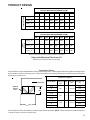
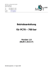
NOTE: Airflow area will be reduced by approximately 18% if duct flanges are not unfolded. This could cause performance issues and noise issues.
¾"
28¾"
LEFT SIDE VIEW
PRODUCT DIMENSIONS
GCVC9/ACVC9_____X*
PRODUCT DESIGN
PRESSURE SWITCH TRIP POINTS AND USAGE CHART
MODEL
NEGATIVE PRESSURE
ID BLOWER
WITH FLUE
NOT FIRING
TYPICAL SEA LEVEL
DATA
NEGATIVE PRESSURE
ID BLOWER
WITH FLUE
FIRING
TYPICAL SEA LEVEL
(1)
DATA
NEGATIVE PRESSURE
COIL COVER
WITH FLUE
NOT FIRING
TYPICAL S EA LEVEL
(2)
DATA
NEGATIVE PRESSURE
COIL COVER
WITH FLUE
FIRING
TYPICAL SEA LEVEL
(1)
DATA
(2)
LOW FIRE
HIGH FIRE
LOW FIRE
HIGH FIRE
LOW FIRE
HIGH FIRE
LOW FIRE
HIGH FIRE
GMVC950453BX*
GMVC950704CX*
AMVC950453BX*
AMVC950704CX*
-0.45
-0.92
-0.30
-0.75
-0.25
-0.25
-0.10
-0.10
GMVC950905CX*
AMVC950905CX*
-0.75
-1.60
-.060
-1.40
-0.25
-0.25
-0.10
-0.10
GMVC950905DX*
GMVC951155DX*
AMVC950905DX*
AMVC951155DX*
-0.65
-1.27
-0.50
-1.10
-0.25
-0.25
-0.10
-0.10
GCVC950714CX*
ACVC950714CX*
-0.95
-1.80
-0.80
-1.60
-0.25
-0.25
-0.10
-0.10
GCVC950915DX*
ACVC950915DX*
-0.95
-1.80
-0.80
-1.60
-0.25
-0.25
-0.10
-0.10
GCVC91155DX*
ACVC951155DX*
-0.35
-0.70
-0.20
-0.55
-0.52
-0.52
-0.37
-0.37
(1) Dat a given is least negative pressure required for pressure switch to close.
(2) Dat a given is least negative pressure required for pressure switch to remain closed.
Not e: The typical sea level negative pressure data represent s the minimum pressures expected. S hort er length of flue pipe or single pipe systems compared to
dual pipe systems should show higher (greater negat ive) press ures.
9
10
20197313
0130F000 70
0130F000 70
20197308
20197308
20197308
COIL COVER
PRESSURE
SWITCH
PART #
-0.20
-0.80
-0.80
-0.50
-0.60
-0.30
LOW
FIRE
-0.55
-1.60
-1.60
-1.10
-1.40
-0.75
HIGH
FIRE
TRIP POINT
ID BLOWER
PRESSURE
SWITCH
111 77118
0130F00100
0130F00100
111 77114
0130F00251
111 77113
ID BLOWER
PRESSURE
SWITCH
PART #
-0.37
N/A
N/A
-0.10
N/A
-0.10
LOW
FIRE
-0.37
N/A
N/A
-0.10
N/A
-0.10
HIGH
FIRE
TRIP POINT
COIL COVER
PRESSURE
SWITCH
-0.15
N/A
N/A
-0.38
N/A
-0.22
LOW
FIRE
-0.30
N/A
N/A
-0.82
N/A
-0.55
HIGH
FIRE
TRIP POINT
ID BLOWER
PRESSURE
SWITCH
7,001 ft. to 11,000 ft.
HAPS31
N/A
N/A
HAPS29
11177116
N/A
HAPS28
11177115
HIGH
ALTITUDE
KIT
Note: All negative press ure readings are in inches of water column (" w.c.).
Note: Replacement pressure switch number is listed below high altitude kit number.
Note: All installat ions above 7,000 ft. require a pressure switch change. For installations in Canada the *MVC95 & *CVC9/95 furnaces are certified only to 4500 ft.
-0.37
-0.10
-0.3 7
-0.1 0
GCVC950714CX*
ACVC950714CX*
-0.10
-0.10
-0.1 0
GMVC950905DX*
GMVC951155DX*
AMV C950905DX*
AMV C951155DX*
-0.10
-0.10
HIGH
FIRE
-0.1 0
-0.1 0
GMVC950905CX*
AMV C950905CX*
GCVC950915DX*
ACVC950915DX*
GCVC91155DX*
ACVC91155DX*
-0.1 0
LOW
FIRE
GMVC950453BX*
GMVC950704CX*
AMV C950453BX*
AMV C950704CX*
MODEL
TRIP POINT
COIL COVER
PRESSURE
SWITCH
0 to 7,000 ft.
PRESSURE SWITCH TRIP POINTS AND USAGE CHART
PRODUCT DESIGN
PRODUCT DESIGN
PRIMARY LIMIT
Part Number
20162903
20162904
20162905
20162907
20162908
0130F001 05
Open Setting (°F)
160
150
145
155
170
130
GMVC950453BX*
AMVC950453BX*
---
---
1
---
---
---
GMVC950704CX*
AMVC950704CX*
---
---
---
1
---
---
GMVC950905CX*
AMVC950905CX*
---
---
---
---
---
1
GMVC950905DX*
AMVC950905DX*
---
---
1
---
---
---
GMVC951155DX*
AMVC951155DX*
---
1
---
---
---
---
GCVC950714CX*
ACVC950714CX*
---
1
---
---
---
---
GCVC950915DX*
ACVC950915DX*
---
---
---
---
---
1
GCVC91155DX*
ACVC951155DX*
----
----
1
----
----
---
ROLLOUT LIMIT SWITCHES
Part Number
10123512
1012 3517
10123518
1 0123533
10123534
10 123537
Open Setting (°F)
325
210
170
200
220
190
GMVC950453 BX*
AMVC950453BX*
---
---
1
---
---
---
GMVC950704 CX*
AMVC950704CX*
---
---
---
2
---
---
GMVC950905 CX*
AMVC950905CX*
---
---
---
2
---
---
GMVC950905 DX*
AMVC950905DX*
---
---
---
---
---
2
GMVC951155 DX*
AMVC951155DX*
---
---
---
2
---
---
GCVC950714CX*
ACVC950714CX*
----
2
----
----
----
----
---
2
---
---
---
---
----
2
----
----
----
---
GCVC950915DX*
ACVC950915DX*
GCVC91155 DX*
ACVC951 155DX*
AUXILIARY LIMIT SWIT CHES
Part Number
10123534
10123535
10123537
10123536
10123533
0130F00038
Open Setting (°F)
220
150
190
180
200
120
GMVC950453BX*
AMVC95045 3BX*
---
2
---
---
---
---
GMVC950704CX*
AMVC95070 4CX*
---
---
2
---
---
---
GMVC950905CX*
AMVC95090 5CX*
---
---
---
2
---
---
GMVC950905DX*
AMVC95090 5DX*
---
---
---
2
---
---
GMVC951155DX*
AMVC95115 5DX*
---
---
---
---
2
---
GCVC950714CX*
ACVC950714CX*
---
---
---
---
---
2
---
---
---
---
---
2
---
---
---
---
---
2
GCVC950915DX*
ACVC950915DX*
GCVC91155DX*
ACVC951155DX*
11
PRODUCT DESIGN
Thermostats:
ComfortNet™ CTK0* Thermostat Kit
Filters:
Filters are required with this furnace and must be provided by the installer. The filters used must comply with UL900 or
CAN/ULCS111 standards. Installing this furnace without filters will void the unit warranty
Upflow Filters
Return air filters may be installated at the furnace side and/or bottom return openings. The furnace bottom return opening
and side openings will accommodate the following filter sizes depending on cabinet size:
Side Re turn Ope ning(s)
Bottom Re turn Ope ning
Cabinet
W idth
(in.)
Nominal
Filter Size
(in.)
Approx.
Flow Area
(in 2 )
Cabinet
W idth
(in.)
Nominal
Filter Size
(in.)
Approx.
Flow Area
(in 2 )
All
16 x 25 x 1
400
17-1/2
14 x 25 x 1
350
21
16 x 25 x 1
400
24-1/2
20 x 25 x 1
500
Refer to Minimum Filter Area tables to determine filter area requirement. NOTE: Filters can also be installed elsewhere in
the duct system such as a central return.
Input__Airflow
UP FLOW
COOLING AIRFLOW REQUIREMENT (CFM)
600
800
1000
1200
1400
1600
1800
2000
0453__X*
415*
415*
480
576
---
---
---
---
0704__X*
---
---
636*
636*
672
768
---
---
0905__X*
---
---
---
826*
826*
826*
864
960
1155__X*
---
---
---
875*
875*
875*
875*
960
Input
Airflow
COUNTERFLOW
COOLING AIRFLOW REQUIREMENT (CFM)
600
800
1000
1200
1400
1600
1800
2000
0714__X*
---
---
634*
634*
672
768
---
---
0915__X*
---
---
---
819*
819*
819*
864
960
1155__X*
---
---
---
860*
860*
860*
864
960
*Minimum filter area dictated by heating airflow requirement.
Disposable Minimum Filter Area (in2)
[Based on a 300 ft/min filter face velocity]
12
PRODUCT DESIGN
Input__Airflow
UPFLOW
COOLING AIRFLOW REQUIREMENT (CFM)
600
800
1000
1200
1400
1600
1800
2000
0453__X*
207*
207*
240
288
---
---
---
---
0704__X*
---
---
318*
318*
336
384
---
---
0905__X*
---
---
---
413*
413*
413*
432
480
1155__X*
---
---
---
437*
437*
437*
432
480
Input
Airflow
COUNTERFLOW
COOLING AIRFLOW REQUIREMENT (CFM)
600
800
1000
1200
1400
1600
1800
2000
0714__X*
---
---
316*
316*
336
384
---
---
0915__X*
---
---
---
409*
409*
409*
432
480
1155__X*
---
---
---
430*
430*
430*
432
480
*Minimum filter area dictated by heating airflow requirement.
Disposable Minimum Filter Area (in2)
[Based on a 600 ft/min filter face velocity]
Counterflow Filters
Return air filters may be installated at the at the counterflow top return. A field supplied center filter support must be provided
by the installer in order to use the top return. The furnace will accommodate the following counterflow top return filter sizes
depending on cabinet size:
Counterflow Top Return
Return Air
Optional
Access
Door
Cabinet Width
Filter Area
2
(in )
Qty
Filter Size Dimension "A"
(in)
(in)
17 1/2
"A"
Min
21
14.2
600
2
15 X 20 X 1
13.0
24 1/2
11.3
17 1/2
19.7
21
800
2
20 X 20 X 1
24 1/2
17.7
17 1/2
21
24 1/2
18.8
25.0
1000
2
25 X 20 X 1
24.3
23.4
Refer to Minimum Filter Area tables to determine filter area requirement. NOTE: Filters can also be installed elsewhere
in the duct system such as a central return.
13
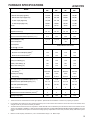
FURNACE SPECIFICATIONS
A/GMVC95
*MVC950453
BX*
*MVC950704
CX*
*MVC950905
CX*
*MVC950905
DX*
*MVC951155
DX*
Natural Gas Input (High Fire)
45,000
68,000
90,000
90,000
113,000
Natural Gas Output (High Fire)
43,200
65,300
86,500
86,500
108,600
LP Gas Input (High Fire)
40,500
61,200
81,000
81,000
101,700
LP Gas Output (High Fire)
38,900
58,800
77,800
77,800
97,700
96.1%
96.1%
96.1%
96.1%
96.1%
Rated External Static (" w.c.)
.20 - .50
.20 - .50
.20 - .50
.20 - .50
.20 - .50
Temperature Rise (°F)
30 - 60
30 - 60
30 - 60
30 - 60
35 - 65
ID Blower Pressure Switch Trip Point (" w.c.)
-0.75
-0.75
-1.40
-1.10
-1.10
Front Cover Pressure Switch Trip Point (" w.c.)
-0.10
-0.10
-0.10
-0.10
-0.10
Blower Wheel (D" x W")
10 x 8
10 x 10
11 x 10
11 x 10
11 x 10
1/2
3/4
1
1
1
MODEL
BTUH
A.F.U.E.
Blower Horsepower
Blower Speeds
Refer to Blower CFM Charts
Max CFM @ 0.5 E.S.P.
Power Supply
115-60-1
115-60-1
115-60-1
115-60-1
115-60-1
11.3
14.1
14.4
14.4
14.4
15.0
15.0
15.0
15.0
15.0
Transformer (VA)
40
40
40
40
40
Primary Limit Setting (°F)
145
155
130
145
150
Auxiliary Limit Setting (°F)
150
190
180
180
200
Rollout Limit Setting (°F)
170
200
200
190
200
30 secs.
30 secs.
30 secs.
30 secs.
30 secs.
150 secs.
150 secs.
150 secs.
150 secs.
150 secs.
5 sec
5 sec
5 sec
5 sec
5 sec
45 secs.
45 secs.
45 secs.
45 secs.
45 secs.
7 / 11
7 / 11
7 / 11
7 / 11
7 / 11
Manifold Pressure (Natural/Propane) ("w.c.)
3.5 / 10
3.5 / 10
3.5 / 10
3.5 / 10
3.5 / 10
Orifice Size (Natural/Propane)
43 / 55
43 / 55
43 / 55
43 / 55
43 / 55
2
3
4
4
5
2
2
2
2
2
2
2
2
2
2
123
142
150
155
165
(1)
Minimum Circuit Ampacity (MCA)
(2)
Maximum Overcurrent Device
Fan Delay On Heating
Off Heating
(3)
Fan Delay On Cooling
Off Cooling
Gas Supply Pressure (Natural/Propane) ("w.c.)
Number of Burners
(4)
Vent Connector Diameter (inches)
Combustion Air Connector Diameter (inches)
Shipping Weight (lbs.)
(5)
NOTE: Low fire inpu t is 70% of high fire input
1.
These furnaces are manufactured for natural gas operation. Optional Kits are available for conversion to propane gas operation.
2.
For elevations above 2000 ft. the rating should be reduced by 4% for each 1000 ft. above sea level. The furnace must not be derated, orifice
changes should only be made if necessary for altitude.
3.
The total heat loss from the structure as expressed in TOTAL BTU/HR must be calculated by the manufactures method in accordance with the
"A.S.H.R.A.E. GUIDE" or "MANUAL J-LOAD CALCULATIONS" published by the AIR CONDITIONING CONTRACTORS OF AMERICA. The total
heat loss calculated should be equal to or less than the heating capacity. Output based on D.O.E. test procedures, steady state efficiency times
output.
4.
Minimum Circuit Ampacity calculated as: (1.25 x Circulator Blower Amps) + I.D. Blower Amps.
14
FURNACE SPECIFICATIONS
A/GCVC9
GCVC91155 ACVC951155 *CVC950714 *CVC950915
DX*
DX*
CX*
DX*
MODEL
BTUH
Natural Gas Input (High Fire)
1 13,000
113,000
68,000
90,000
Natu ral Gas Output (Hig h Fire)
1 05,100
105,100
64,600
85,500
LP Gas Input (High Fire)
1 01,700
101,700
61,200
81,000
LP Gas Output (High Fi re)
94,600
94,600
58,100
77,000
93.0%
93.0%
95.0%
95.0%
.20 - .50
.20 - .50
.20 - .50
.20 - .50
40 - 70
40 - 70
25 - 55
25 - 55
ID Blower Pressure Switch High Fire Trip Point (" w.c.)
-0 .55
-0.55
-1.60
-1.60
Front Cover Pressure Switch Trip Point (" w.c.)
-0 .37
-0.37
-0.10
-0.10
11 x 1 0
11 x 10
10 x 10
11 x 10
A.F.U.E.
Rated External Static (" w.c.)
Temperature Rise (°F)
Blower Wheel (D" x W")
Blower Horsep ower
1
1
3/4
Blower Speeds
1
Re fer to Blower CFM Charts
Max CFM @ 0.5 E.S.P.
Power Supply
115-60-1
115-60-1
1 15-60-1
115-60-1
14.4
14 .4
11.2
15.0
15.0
15 .0
15.0
15.0
40
40
40
40
Primary Limit Setting (°F)
145
145
150
13 0
Auxiliary Limit Setting (°F)
120
120
120
12 0
Rollout Limit Setting (°F)
210
210
210
21 0
30 secs.
30 secs.
30 secs.
30 secs.
150 secs.
150 secs.
150 secs.
150 secs.
5 sec
5 sec
5 sec
5 sec
45 secs.
45 secs.
45 secs.
45 secs.
7 / 11
7 / 11
7 / 11
7 / 11
Manifold Pressure (Natural/Pro pane) ("w.c.)
3.5 / 10
3.5 / 10
3 .5 / 10
3.5 / 10
Orifice Size (Natural/Propane)
43 / 55
43 / 55
43 / 55
43 / 55
5
5
3
4
2
2
2
2
2
2
2
2
160
160
139
15 8
(1 )
Minimum Circuit Ampacity (MCA)
Maximum Overcurrent Device
(2)
Transforme r (VA)
Fan Delay On Heating
Off Hea ting
(3)
Fan Delay On Cooling
Off Coo ling
Gas Supp ly Pressure (Natura l/Propane) ("w.c.)
Number of Burners
Vent Con nector Diameter (inches)
(4)
(5)
Combustion Air Connector Diameter (in ches)
Shippi ng Weight (lbs.)
NOTE: Lo w fire in put is 70% of high fir e inp ut
1.
These furnaces are manufactured for natural gas operation. Optional Kits are available for conversion to propane gas operation.
2.
For elevations above 2000 ft. the rating should be reduced by 4% for each 1000 ft. above sea level. The furnace must not be derated, orifice
changes should only be made if necessary for altitude.
3.
The total heat loss from the structure as expressed in TOTAL BTU/HR must be calculated by the manufactures method in accordance with the
"A.S.H.R.A.E. GUIDE" or "MANUAL J-LOAD CALCULATIONS" published by the AIR CONDITIONING CONTRACTORS OF AMERICA. The total
heat loss calculated should be equal to or less than the heating capacity. Output based on D.O.E. test procedures, steady state efficiency times
output.
4.
Minimum Circuit Ampacity calculated as: (1.25 x Circulator Blower Amps) + I.D. Blower Amps.
15
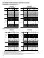
BLOWER PERFORMANCE SPECIFICATIONS
*MVC950453BX Cooling/Heating Speed Charts
*MVC950453BX
Cooling Speed
( @ .1" - .8" w.c. ESP)
Tap
A
B
C
D
Adjust
Minus 10%
Minus 5%
Normal
Plus 5%
Plus 10%
Minus 10%
Minus 5%
Normal
Plus 5%
Plus 10%
Minus 10%
Minus 5%
Normal
Plus 5%
Plus 10%
Minus 10%
Minus 5%
Normal
Plus 5%
Plus 10%
High-Stage
CFM
540
570
600
630
660
720
760
800
840
880
900
950
1,000
1,050
1,100
1,080
1,140
1,200
1,260
1,320
*MVC950453BX
Heating Speed
(@ .1" - .5" w.c. ESP; Rise Range: 30 - 60°F)
Low-Stage
CFM
351
371
390
410
429
468
494
520
546
572
585
618
650
683
715
702
741
780
819
858
Tap
A
B
C
D
Adjust
Minus 10%
Minus 5%
Normal
Plus 5%
Plus 10%
Minus 10%
Minus 5%
Normal
Plus 5%
Plus 10%
Minus 10%
Minus 5%
Normal
Plus 5%
Plus 10%
Minus 10%
Minus 5%
Normal
Plus 5%
Plus 10%
High-Stage
CFM
713
752
792
832
871
778
821
864
907
950
842
889
936
983
1,030
907
958
1,008
1,058
1,109
Low-Stage
CFM
495
523
550
578
605
540
570
600
630
660
585
618
650
683
715
630
665
700
735
770
Rise
(°F)
57
49
41
43
46
52
49
47
45
43
48
45
43
41
39
45
42
40
38
36
*MVC950704CX Cooling/Heating Speed Charts
*MVC950704CX
Cooling Speed
( @ .1" - .8" w.c. ESP)
Tap
A
B
C
D
Adjust
Minus 10%
Minus 5%
Normal
Plus 5%
Plus 10%
Minus 10%
Minus 5%
Normal
Plus 5%
Plus 10%
Minus 10%
Minus 5%
Normal
Plus 5%
Plus 10%
Minus 10%
Minus 5%
Normal
Plus 5%
Plus 10%
High-Stage
CFM
540
570
600
630
660
720
760
800
840
880
990
1,045
1,100
1,155
1,210
1,286
1,358
1,429
1,500
1,572
*MVC950704CX
Heating Speed
(@ .1" - .5" w.c. ESP; Rise Range: 30 - 60°F)
Low-Stage
CFM
351
371
390
410
429
468
494
520
546
572
644
679
715
751
787
836
883
929
975
1,022
Tap
A
B
C
D
Adjust
Minus 10%
Minus 5%
Normal
Plus 5%
Plus 10%
Minus 10%
Minus 5%
Normal
Plus 5%
Plus 10%
Minus 10%
Minus 5%
Normal
Plus 5%
Plus 10%
Minus 10%
Minus 5%
Normal
Plus 5%
Plus 10%
High-Stage
CFM
1,089
1,150
1,210
1,271
1,331
1,193
1,259
1,325
1,391
1,458
1,296
1,368
1,440
1,512
1,584
1,400
1,477
1,555
1,633
1,711
Low-Stage
CFM
756
798
840
882
924
828
874
920
966
1,012
900
950
1,000
1,050
1,100
972
1,026
1,080
1,134
1,188
Rise
(°F)
56
53
50
48
46
51
48
46
44
42
47
44
42
40
38
43
41
39
37
35
1.
All furnaces ship as high speed for cooling. Installer must adjust blower speed as needed.
2.
For most jobs, about 400 CFM per ton when cooling is desirable.
3.
Do not operate above .5" w.c. ESP in heating mode. Operating CFM between .5" and .8" w.c. is tabulated for cooling purposes only.
4.
Continuous fan speeds of 25%, 50%, 75% of maximum cooling airflow are available when using a communicating thermostat and 25%, 50%, 75%, 100%
of maximum cooling airflow are available in legacy mode by setting dip switches
16
BLOWER PERFORMANCE SPECIFICATIONS
*MVC950905CX Cooling/Heating Speed Charts
*MVC950905CX
Cooling Speed
( @ .1" - .8" w.c. ESP)
Tap
A
B
C
D
*MVC950905CX
Heating Speed
(@ .1" - .5" w.c. ESP; Rise Range: 30 - 60°F)
Adjust
High-Stage
CFM
Low-Stage
CFM
Minus 10%
Minus 5%
Normal
Plus 5%
Plus 10%
Minus 10%
Minus 5%
Normal
Plus 5%
Plus 10%
Minus 10%
Minus 5%
Normal
Plus 5%
Plus 10%
Minus 10%
Minus 5%
Normal
Plus 5%
Plus 10%
729
770
810
851
891
990
1,045
1,100
1,155
1,210
1,323
1,397
1,470
1,544
1,617
1,629
1,720
1,810
1,901
1,991
495
523
550
578
605
693
732
770
809
847
900
950
1,000
1,050
1,100
1,125
1,188
1,250
1,313
1,375
Adjust
High-Stage
CFM
Low-Stage
CFM
Rise
(°F)
Minus 10%
Minus 5%
Normal
Plus 5%
Plus 10%
Minus 10%
Minus 5%
Normal
Plus 5%
Plus 10%
Minus 10%
Minus 5%
Normal
Plus 5%
Plus 10%
Minus 10%
Minus 5%
Normal
Plus 5%
Plus 10%
1,341
1,416
1,490
1,565
1,639
1,413
1,492
1,570
1,649
1,727
1,521
1,606
1,690
1,775
1,859
1,602
1,691
1,780
1,869
1,958
945
998
1,050
1,103
1,155
1,008
1,064
1,120
1,176
1,232
1,080
1,140
1,200
1,260
1,320
1,125
1,188
1,250
1,313
1,375
60
57
54
51
49
57
54
51
49
47
53
50
48
45
43
50
47
45
43
41
Tap
A
B
C
D
*MVC950905DX Cooling/Heating Speed Charts
*MVC950905DX
Cooling Speed
( @ .1" - .8" w.c. ESP)
Tap
A
B
C
D
*MVC950905DX
Heating Speed
(@ .1" - .5" w.c. ESP; Rise Range: 30 - 60°F)
Adjust
High-Stage
CFM
Low-Stage
CFM
Minus 10%
Minus 5%
Normal
Plus 5%
Plus 10%
Minus 10%
Minus 5%
Normal
Plus 5%
Plus 10%
Minus 10%
Minus 5%
Normal
Plus 5%
Plus 10%
Minus 10%
Minus 5%
Normal
Plus 5%
Plus 10%
720
760
800
840
880
900
950
1,000
1,050
1,100
1,260
1,330
1,400
1,470
1,540
1,620
1,710
1,800
1,890
1,980
468
494
520
546
572
644
679
715
751
787
819
865
910
956
1,001
1,053
1,112
1,170
1,229
1,287
Adjust
High-Stage
CFM
Low-Stage
CFM
Rise
(°F)
Minus 10%
Minus 5%
Normal
Plus 5%
Plus 10%
Minus 10%
Minus 5%
Normal
Plus 5%
Plus 10%
Minus 10%
Minus 5%
Normal
Plus 5%
Plus 10%
Minus 10%
Minus 5%
Normal
Plus 5%
Plus 10%
1,458
1,539
1,620
1,701
1,782
1,549
1,635
1,721
1,807
1,893
1,640
1,731
1,822
1,913
2,004
1,730
1,826
1,922
2,018
2,114
1,013
1,069
1,125
1,181
1,238
1,076
1,135
1,195
1,255
1,315
1,139
1,202
1,265
1,328
1,392
1,202
1,268
1,335
1,402
1,469
55
52
50
47
45
52
49
47
45
43
49
46
44
42
40
47
44
42
40
38
Tap
A
B
C
D
1.
All furnaces ship as high speed for cooling. Installer must adjust blower speed as needed.
2.
For most jobs, about 400 CFM per ton when cooling is desirable.
3.
Do not operate above .5" w.c. ESP in heating mode. Operating CFM between .5" and .8" w.c. is tabulated for cooling purposes only.
4.
Continuous fan speeds of 25%, 50%, 75% of maximum cooling airflow are available when using a communicating thermostat and 25%, 50%, 75%, 100%
of maximum cooling airflow are available in legacy mode by setting dip switches
17
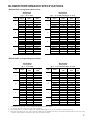
BLOWER PERFORMANCE SPECIFICATIONS
*MVC951155DX Cooling/Heating Speed Charts
*MVC951155DX
Cooling Speed
( @ .1" - .8" w.c. ESP)
Tap
A
B
C
D
*MVC951155DX
Heating Speed
(@ .1" - .5" w.c. ESP; Rise Range: 35 - 65°F)
Adjust
High-Stage
CFM
Low-Stage
CFM
Minus 10%
Minus 5%
Normal
Plus 5%
Plus 10%
Minus 10%
Minus 5%
Normal
Plus 5%
Plus 10%
Minus 10%
Minus 5%
Normal
Plus 5%
Plus 10%
Minus 10%
Minus 5%
Normal
Plus 5%
Plus 10%
720
760
800
840
880
990
1,045
1,100
1,155
1,210
1,260
1,330
1,400
1,470
1,540
1,620
1,710
1,800
1,890
1,980
468
494
520
546
572
644
679
715
751
787
819
865
910
956
1,001
1,053
1,112
1,170
1,229
1,287
Adjust
High-Stage
CFM
Low-Stage
CFM
Rise
(°F)
Minus 10%
Minus 5%
Normal
Plus 5%
Plus 10%
Minus 10%
Minus 5%
Normal
Plus 5%
Plus 10%
Minus 10%
Minus 5%
Normal
Plus 5%
Plus 10%
Minus 10%
Minus 5%
Normal
Plus 5%
Plus 10%
1,594
1,682
1,771
1,860
1,948
1,640
1,731
1,822
1,913
2,004
1,685
1,778
1,872
1,966
2,059
1,730
1,826
1,922
2,018
2,114
1,107
1,169
1,230
1,292
1,353
1,139
1,202
1,265
1,328
1,392
1,170
1,235
1,300
1,365
1,430
1,202
1,268
1,335
1,402
1,469
63
60
57
54
52
62
59
56
53
50
60
57
54
51
49
58
55
53
50
48
Tap
A
B
C
D
1.
All furnaces ship as high speed for cooling. Installer must adjust blower speed as needed.
2.
For most jobs, about 400 CFM per ton when cooling is desirable.
3.
Do not operate above .5" w.c. ESP in heating mode. Operating CFM between .5" and .8" w.c. is tabulated for cooling purposes only.
4.
Continuous fan speeds of 25%, 50%, 75% of maximum cooling airflow are available when using a communicating thermostat and 25%, 50%, 75%, 100%
of maximum cooling airflow are available in legacy mode by setting dip switches
18
BLOWER PERFORMANCE SPECIFICATIONS
*CVC950714CX Cooling/Heating Speed Charts
*CVC950714CX
Cooling Speeds
( @ .1" - .8" w.c. ESP)
Tap
A
B
C
D
*CVC950714CX
Heating Speed
(@ .1" - .5" w.c. ESP; Rise Range: 25 - 55°F)
Adjust
High-Stage
CFM
Low-Stage
CFM
Minus 10%
Minus 5%
Normal
Plus 5%
Plus 10%
Minus 10%
Minus 5%
Normal
Plus 5%
Plus 10%
Minus 10%
Minus 5%
Normal
Plus 5%
Plus 10%
Minus 10%
Minus 5%
Normal
Plus 5%
Plus 10%
594
627
660
693
726
747
789
830
872
913
1,017
1,074
1,130
1,187
1,243
1,314
1,387
1,460
1,533
1,606
324
342
360
378
396
468
494
520
546
572
702
741
780
819
858
864
912
960
1,008
1,056
Adjust
High-Stage
CFM
Low-Stage
CFM
Rise
Minus 10%
Minus 5%
Normal
Plus 5%
Plus 10%
Minus 10%
Minus 5%
Normal
Plus 5%
Plus 10%
Minus 10%
Minus 5%
Normal
Plus 5%
Plus 10%
Minus 10%
Minus 5%
Normal
Plus 5%
Plus 10%
1,107
1,169
1,230
1,292
1,353
1,215
1,283
1,350
1,418
1,485
1,323
1,397
1,470
1,544
1,617
1,440
1,520
1,600
1,680
1,760
783
827
870
914
957
855
903
950
998
1,045
936
988
1,040
1,092
1,144
1,017
1,074
1,130
1,187
1,243
77
73
69
66
63
71
68
64
61
58
65
61
58
55
53
59
56
53
51
49
Tap
A
B
C
D
*CVC950915DX Cooling/Heating Speed Charts
*CVC950915DX
Cooling Speeds
( @ .1" - .8" w.c. ESP)
Tap
A
B
C
D
*CVC950915DX
Heating Speed
(@ .1" - .5" w.c. ESP; Rise Range: 25 - 55°F)
Adjust
High-Stage
CFM
Low-Stage
CFM
Adjust
High-Stage
CFM
Low-Stage
CFM
Rise
Minus 10%
729
Minus 5%
770
504
Minus 10%
1,458
1,008
80
532
Minus 5%
1,539
1,064
Normal
810
560
76
Normal
1,620
1,120
72
Plus 5%
851
588
Plus 5%
1,701
1,176
68
Tap
A
Plus 10%
891
616
Plus 10%
1,782
1,232
65
Minus 10%
999
666
Minus 10%
1,575
1,098
73
Minus 5%
1,055
703
Minus 5%
1,663
1,159
69
Normal
1,110
740
Normal
1,750
1,220
66
B
Plus 5%
1,166
777
Plus 5%
1,838
1,281
63
Plus 10%
1,221
814
Plus 10%
1,925
1,342
60
Minus 10%
1,287
828
Minus 10%
1,674
1,152
70
Minus 5%
1,359
874
Normal
1,430
920
C
Minus 5%
1,767
1,216
66
Normal
1,860
1,280
63
Plus 5%
1,502
966
Plus 5%
1,953
1,344
60
Plus 10%
1,573
1,012
Plus 10%
2,046
1,408
57
Minus 10%
1,674
1,071
Minus 10%
1,773
1,206
67
Minus 5%
1,767
1,131
Minus 5%
1,872
1,273
63
Normal
1,860
1,190
Normal
1,970
1,340
60
Plus 5%
1,953
1,250
Plus 5%
2,069
1,407
57
Plus 10%
2,046
1,309
Plus 10%
2,167
1,474
55
D
1.
All furnaces ship as high speed for cooling. Installer must adjust blower speed as needed.
2.
For most jobs, about 400 CFM per ton when cooling is desirable.
3.
Do not operate above .5" w.c. ESP in heating mode. Operating CFM between .5" and .8" w.c. is tabulated for cooling purposes only.
4.
Continuous fan speeds of 25%, 50%, 75% of maximum cooling airflow are available when using a communicating thermostat and 25%, 50%, 75%, 100%
of maximum cooling airflow are available in legacy mode by setting dip switches
19
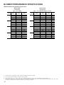
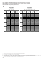
BLOWER PERFORMANCE SPECIFICATIONS
GCVC951155DX Cooling/Heating Speed Charts
Tap
A
B
C
D
GCVC91155DX*
ACVC951155DX*
GCVC91155DX*
ACVC951155DX*
Cooling Speeds
(@.1" -.8" w.c. ESP)
He ating Speeds
(@.1" -.5" w.c. ESP; Rise Range: 40 - 70°F)
Adjust
High-Stage
CFM
Low-Stage
CFM
Minus 10%
Minu s 5%
705
744
457
483
508
533
559
621
656
690
725
759
815
861
906
951
997
1,049
1,107
1,165
1,223
1,282
Normal
783
Plus 5%
822
Plus 10%
861
Minus 10%
982
Minu s 5%
Normal
1,036
1,091
Plus 5%
1,146
Plus 10%
1,200
Minus 10%
1,265
Minu s 5%
1,336
Normal
1,406
Plus 5%
1,476
Plus 10%
1,547
Minus 10%
Minu s 5%
1,628
1,719
Normal
1,809
Plus 5%
1,899
Plus 10%
1,990
Tap
A
B
C
D
Adjust
High-Stage
CFM
Low-Stage
CFM
Rise
Minus 10%
Minus 5%
1,583
1,671
Normal
1,759
1,093
1,153
1,214
1,275
1,335
1,106
1,168
1,229
1,290
1,352
1,166
1,231
1,296
1,361
1,426
1,172
1,237
1,302
1,367
1,432
63
59
56
53
51
61
58
55
52
50
60
57
54
51
49
59
56
53
50
48
Plu s 5%
1,847
Plus 10%
1,935
Minus 10%
1,612
Minus 5%
Normal
1,701
1,791
Plu s 5%
1,881
Plus 10%
1,970
Minus 10%
1,654
Minus 5%
1,746
Normal
1,838
Plu s 5%
1,930
Plus 10%
2,022
Minus 10%
Minus 5%
1,690
1,784
Normal
1,878
Plu s 5%
1,972
Plus 10%
2,066
1.
All furnaces ship as high speed for cooling. Installer must adjust blower speed as needed.
2.
For most jobs, about 400 CFM per ton when cooling is desirable.
3.
Do not operate above .5" w.c. ESP in heating mode. Operating CFM between .5" and .8" w.c. is tabulated for cooling purposes only.
4.
Continuous fan speeds of 25%, 50%, 75% of maximum cooling airflow are available when using a communicating thermostat and 25%, 50%, 75%, 100%
of maximum cooling airflow are available in legacy mode by setting dip switches
20
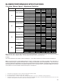
BLOWER PERFORMANCE SPECIFICATIONS
Circulator Blower Speed Adjustment Switches
Switch Bank
Purpose
Heating Off Delay
S1
Thermostat Setup
Cooling Airflow
S3
Trim
Ramping Profile
S4
Heating Airflow
Dehum
Trim
S5
Continuous Fan
Function
90
120
150
180
2 Stage Stat
2 Stage Stat
1 Stg Stat 5 min delay
1 Stg Stat auto delay
A
B
C
D
Add 5%
Minus 5%
Add 10%
Minus 10%
A
B
C
D
A
B
C
D
Disabled
Enabled
Disabled
Enabled
25%
50%
75%
100%
1
Off
On
Off
On
Off
On
Off
On
Off
On
Off
On
Dip Switch
2
3
Off
Off
On
On
On
On
Off
Off
Off
Off
On
On
Off
On
Off
On
Off
Off
On
On
Off
On
Off
On
4
On
Off
Off
On
Off
Off
On
On
Off
Off
On
On
Off
On
Off
On
Off
On
Off
On
Off
Off
On
On
Note: There are dual 7-segment LED's adjacent to the selection dipswitches. The airflow (rounded to the nearest 100 CFM) is
displayed on the dual 7-segment LED's. The CFM display alternates with the operating mode.
Example:
If the airlfow demand is 1230 CFM, the LED's will display 12. If the airflow demand is 1275 CFM, the LED's will display 13.
Note: The optional usage of a dehumidistat allows the furnace’s circulator blower to operate at a slightly lower speed (85% of
desired speed) during a combined thermostat call for cooling and dehumidistat call for dehumidification. This can be done
through an independent dehumidistat or through a thermostat’s DEHUM terminal (if available). This lower blower speed enhances
dehumidification of the conditioned air as it passes through the AC coil. For proper function, a dehumidistat applied to this furnace
must operate on 24 VAC and utilize a switch which opens on humidity rise.
1.
All furnaces ship as high speed for cooling. Installer must adjust blower speed as needed.
2.
For most jobs, about 400 CFM per ton when cooling is desirable.
3.
Do not operate above .5" w.c. ESP in heating mode. Operating CFM between .5" and .8" w.c. is tabulated for cooling purposes only.
4.
Continuous fan speeds of 25%, 50%, 75% of maximum cooling airflow are available when using a communicating thermostat and 25%, 50%, 75%, 100%
of maximum cooling airflow are available in legacy mode by setting dip switches
21
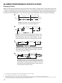
BLOWER PERFORMANCE SPECIFICATIONS
Ramping Profile
Note: The multi-speed circulator blower also offers several custom ON/OFF ramping profiles. These profiles may be used
to enhance cooling performance and increase comfort level. The ramping profiles are selected using DIP switches 5 and
6. Refer to the following figure for switch positions and their corresponding taps. Refer to the bullet points below for a
description of each ramping profile. Verify CFM by noting the number displayed on the dual 7-segment LED display.
100% CFM
100% CFM
OFF
OFF
1 min
Profile A: provides only an OFF delay of one (1)
minute at 100% of the cooling demand airflow.
100% CFM
100% CFM
50% CFM
OFF
OFF
1/2 min
1 min
Profile B: ramps up to full cooling demand airflow by first
stepping up to 50% of the full demand for 30 seconds. The
motor then ramps to 100% of the required airflow. A one (1)
minute OFF delay at 100% of the cooling airflow is provided.
100% CFM
OFF
OFF
Profile C: ramps up to 85% of the full cooling demand airflow
and operates there for approximately 7 1/2 minutes. The motor
then steps up to the full demand airflow. Profile C also has a
one (1) minute 100% OFF delay.
OFF
OFF
Profile D: ramps up to 50% of the demad for 1/2 minute,
then ramps to 85% of the full cooling demand airflow and
operates there for approximately 7 1/2 minutes. The motor
then steps up to the full demand airflow. Profile D has a 1/
2 minute at 50% airflow OFF delay.
1.
All furnaces ship as high speed for cooling. Installer must adjust blower speed as needed.
2.
For most jobs, about 400 CFM per ton when cooling is desirable.
3.
Do not operate above .5" w.c. ESP in heating mode. Operating CFM between .5" and .8" w.c. is tabulated for cooling purposes only.
4.
Continuous fan speeds of 25%, 50%, 75% of maximum cooling airflow are available when using a communicating thermostat and 25%, 50%, 75%, 100%
of maximum cooling airflow are available in legacy mode by setting dip switches
22
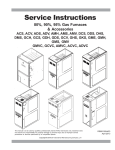
WIRING DIAGRAMS
*CVC9/*MVC95_A*
HIGH VOLTAGE!
DISCONNECT ALL POWER BEFORE SERVICING OR INSTALLING THIS
UNIT. MULTIPLE POWER SOURCES MAY BE PRESENT. FAILURE TO
DO SO MAY CAUSE PROPERTY DAMAGE, PERSONAL INJURY OR DEATH.
TO
115 VAC/ 1 Ø /60 HZ
POWER SUPPLY WITH
OVERCURRENT
PROTECTION DEVICE
GND
3
C
2
PM
C
NO
NO
GY
GY
NO
FRONT COVER
PRESSURE SWITCH
PK
BR
BL
OR
AUTO RESET PRIMARY
LIMIT CONTROL
PU
WH/PU
6
2
3
HEAT OFF DLY
T-STAT
24
VAC
115
VAC
OR
5
1
GY
GY
FUSE
WH
BL
GY
1
4
3
2
WH
BK
BK
RD
WH
5
4
3
2
1
BK
WH
GR
PK
GND
BK
24 VAC
AUTO RESET PRIMARY
MANUAL RESET AUXILIARY LIMIT
LIMIT CONTROL
CONTROLS
PSO (7)
W1
LOW FIRE PRESS.
SWITCH
24V HUM.
PS1 (2)
C
NO
W2
Y2
TO
MICRO
NO
PS2 (12)
HIGH FIRE
PRESS. SWTICH
C
MANUAL RESET ROLLOUT
LIMIT CONTROLS
HLI (1)
O
C
NO
MVL (13)
MVH (14)
FRONT COVER
PRESSURE SWITCH
C
MVC (8)
BK
GND
TR (11)
TO
R
GAS
VALVE
GND (4)
+ VDC (1)
RX (2)
WH
WH
TO
MICRO
PM
HI
C
GND (5)
WH
BLOWER
COMPARTMENT
DOOR SWITCH
(OPEN WHEN
DOOR OPEN)
CIRCULATOR BLOWER
NEUTRAL
40 VA
TRANSFORMER
TH (4)
HLO (10)
Y1
DEHUM
24 V THERMO STAT CONNECTIONS
24V HUM.
ECM MTR
HARNESS
FLAME SENSOR
115 VAC
G
BK
O
Y1
Y2
W2
C
W1
R
G
2
1
PK
DEHUM
DIAGNOSTIC
LED'S
SEE
NOTE 5
BR
OR
OR
24 V
3A
4
TRANSFORMER
TO +VDC
INTEGRATED CONTROL MODULE
9
CONT FAN
24V THERMOSTAT CONNECTIONS
8
40 VA
R
BK
RD
PK
7
2
BR
OR
TRIM ENABLE
FUSE 3 A
NEUTRAL
HOT SURFACE
IGNITER
FS
GY
3
1
NEUTRAL
ID
BLWR
IND LO
IGN
OR
12
PK
15
11
IND HI
BL
4
NEUTRAL
NEUTRAL
ELECTRONIC
AIR CLEANER
1
TWO-STAGE
INTEGRATED
CONTROL
14
10
2
4 CIRCUIT MOTOR
MODULE
CONNECTOR
DIP SWITCHES
BR
13
RD
BK
BK
BK
DEHUM ENABLE
GY
4
3
HUMIDIFIER
HUMIDIFIER
HUM
EAC
LINE
TRIM %
GN
PU
GND
NEUTRAL
SEE NOTE 6
HUM-OUT
COOL AF
HEAT AF
PK
BK
RD
5 CIRCUIT CONNECTOR
EAC
BL
5
WH
WH
HUM
HUMOUT
HUMIN
NEUTRAL
COOL PRFL
YL
INTEGRATED CONTROL MODULE
YL
FS
LINE
INDOOR
AIR
CIRCULATOR
BLWR
HUM-IN
WH
WH
JUNCTION BOX
INDUCTOR COIL
70kBTU,90kBTU,
115kBTU MODELS
ONLY
LINE
PU
MANUAL RESET
AUXILIARY
LIMIT CONTROL
BK
RD
WH
BLOWER COMPARTMENT
WH
DOOR
SWITCH
GND
BURNER COMPARTMENT
N
DISCONNECT
GN
INDUCED
DRAFT
BLOWER
WH
RD
BK
3
GND
L
WARNING:
DISCONNECT POWER
BEFORE SERVICING.
WIRING TO UNIT
MUST BE PROPERLY
POLARIZED AND
GROUNDED.
CHASSIS GROUND
BL
2
DISCONNECT
FLAME
SENSOR
C
MANUAL RESET ROLLOUT LIMIT
CONTROLS (SINGLE CONTROL ON
45 kBTU)
1
WH
OR
PU
WARNING:DISCONNECT
POWER BEFORE
SERVICING. WIRING
TO UNIT MUST BE
PROPERLY POLARIZED
AND GROUNDED.
N
TO 115VAC/ 1 Ø /60 HZ POWER SUPPLY WITH
OVERCURRENT PROTECTION DEVICE
BR
1
L
BK
PU
RD
WH
HI
HIGH FIRE
PRESSURE
SWITCH
OR
GY
OR
TWO STAGE
GAS VALVE
(HONEY WELL)
C
JUNCTION BOX
YL
BR
PU
2 1
24V HUM.
OR
HOT
LOW FIRE
SURFACE PRESSUR
IGNITER E SWITCH
2 CIRCUIT
CONNECTOR
YL
ID BLOWER TWO-STAGE PRESSURE
SWITCH ASSEMBLY
TX (3)
AUX
INDOOR
AIR
CIRCULATOR
BLWR
INTEGRATED CONTROL MODULE
INDUCTOR COIL
70kBTU,90kBTU,
115kBTU MODELS
ONLY
HUMIDIFIER
NOTES:
1. SET HEAT ANTICIPATOR ON ROOM THERMOSTAT AT 0.7 AMPS.
2. MANUFACTURER'S SPECIFIED REPLACEMENT PARTS MUST BE USED WHEN SERVICING.
3. IF ANY OF THE ORIGINAL WIRE AS SUPPLIED WITH THE FURNACE MUST BE REPLACED,
IT MUST BE REPLACED WITH WIRING MATERIAL HAVING A TEMPERATURE RATING OF
AT LEAST 105$C. USE COPPER CONDUCTORS ONLY.
4. UNIT MUST BE PERMANENTLY GROUNDED AND CONFORM TO N.E.C. AND LOCAL CODES.
5. TO RECALL THE LAST 6 FAULTS, MOST RECENT TO LEAST RECENT, DEPRESS SWITCH
FOR MORE THAN 2 SECONDS WHILE IN STANDBY (NO THERMOSTAT INPUTS)
6. HUMIDIFIER INSTALLATION OPTIONS: USE HUM TERMINAL TO RUN HUMIDIFIER DURING
HEAT CALL (COMMUNICATING OR LEGACY MODES). USE HUM-IN AND HUM-OUT
TERMINALS TO RUN HUMIDIFIER DURING HEAT CALL ( COMMUNICATING MODE OR
LEGACY MODE) OR INDEPENDENTLY FROM HEAT CALL (COMMUNICATING MODE ONLY SETUP IS DONE WITHIN COMMUNICATING THERMOSTAT)
COLOR CODES:
PK PINK
BR BROWN
WH WHITE
BL BLUE
GY GRAY
RD RED
YL YELLOW
OR ORANGE
PU PURPLE
GN GREEN
BK BLACK
LOW VOLTAGE (24V)
LOW VOLTAGE FIELD
HI VOLTAGE (115V)
HI VOLTAGE FIELD
JUNCTION
TERMINAL
INTERNAL TO
INTEGRATED CONTROL
PLUG CONNECTION
EQUIPMENT GND
FIELD GND
FIELD SPLICE
SWITCH (TEMP.)
IGNITER
SWITCH (PRESS.)
OVERCURRENT
PROT. DEVICE
0140F01201-B
Wiring is subject to change. Always refer to the wiring diagram on the unit for the most up-to-date wiring.
23
SCHEMATICS
PK
GN
BK
GROUND TO
SCROLL HOUSING
GND
RD
RX
12 V
TX
S T4
BK
BK
LOAD
TRANSFORMER
BK
2 R C G W1 W 2 Y1 Y2 O DEHUM
DE
HUM
INDUCTOR COIL
(MEDIUM AND LARGE CABINET MODELS ONLY)
ANSI Z21.20 AUTOMATIC IGNITION SYSTEM 24VAC 60Hz 0.8 A. MAX.
R
WH
59-4715 REV. F
7
ST5
BK
3
1 2 R C G W 1 W 2 Y1 Y2 O
Y2
Y1
W2
W1
G
C
R
2
6
4
1
15
10
9
12
13
1
EAC
1
O
DEHUM
WH
FS
LINE
WH
IND-N
IGN-N
IND-L O
IGN
IND-HI
HUM
INTEGRATED CONTROL MODULE
GY
BL
TAB TERMINAL
END
MANUAL
RESET
LIMIT
BK
PK
WH
YL
PIN 5
PIN 4
PIN 3
PIN 2
PIN 1
TO ECM
BLWR MOTOR
RD
BK
GY
BL
ECM BLOWER MOTOR
MANUAL
RESET
LIMIT
PU
TAB TERMINAL
END
HIGH VOLTAGE!
DISCONNECT ALL POWER BEFORE SERVICING OR INSTALLING THIS
UNIT. MULTIPLE POWER SOURCES MAY BE PRESENT. FAILURE TO
DO SO MAY CAUSE PROPERTY DAMAGE, PERSONAL INJURY OR DEATH.
BLOWER ASSEMBLY SCHEMATIC
ACVC9/AMVC95/GCVC9/GMVC95_____X* MODEL FURNACES
This schematic is for reference only. Not all wiring is as shown above,
refer to the appropriate wiring diagram for the unit being serviced.
Wiring is subject to change. Always refer to the wiring diagram on the unit for the most up-to-date wiring.
24
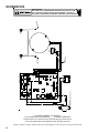
SCHEMATICS
TYPICAL SCHEMATIC
ACVC9/AMV95/GCVC9/GMVC95_____X* MODEL FURNACES
PCBKF103
This schematic is for reference only. Not all wiring is as shown above. Refer to the appropriate wiring diagram for the unit being serviced.
HIGH VOLTAGE!
DISCONNECT ALL POWER BEFORE SERVICING OR INSTALLING THIS
UNIT. MULTIPLE POWER SOURCES MAY BE PRESENT. FAILURE TO
DO SO MAY CAUSE PROPERTY DAMAGE, PERSONAL INJURY OR DEATH.
Wiring is subject to change. Always refer to the wiring diagram on the unit for the most up-to-date wiring.
25