1
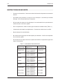
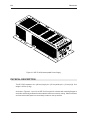
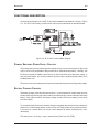
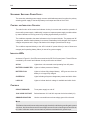
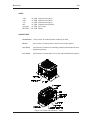
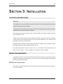
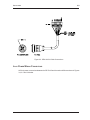
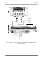
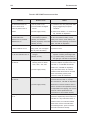
SE 3718S UNINTERRUPTABLE POWER SUPPLY 5452 Betsy Ross Drive Santa Clara, CA 95054-1184 (408) 727-5170 FAX (408) 727-6707 P/N 66109090001, Rev. C II SE 3718S U NINTERRUPTABLE POWER SUPPLY SAFETY INSTRUCTIONS (See Section 1) SICHERHEITVORSCHRIFT (Siehe Kapitel 1) INSTRUCCIONES DE SEGURIDAD (Mire Seccion 1) INSTRUCTIONS DE SECURITE (Voir Section 1) NOTICE The SE 3718S Uninterruptable Power Module manufactured by Westinghouse Security Electronics has been tested and found to comply with the limits for a Class B digital device, pursuant to Part 15 of the FCC rules. These limits are designed to provide reasonable protection against harmful interference in a residential installation. This equipment generates, uses, and can radiate radio frequency energy and, if not installed and used in accordance with the instructions herein, may cause harmful interference to radio communications. However, there is no guarantee that interference will not occur in a particular installation. If this equipment does cause harmful interference to radio or television reception, which can be determined by turning the equipment off and on, the user is encouraged to try to correct the interference by one or more of the following measures: Reorient or locate the receiving antenna. Increase the separation between the equipment and the receiver. Connect the equipment into an outlet on a circuit different from that to which the receiver is connected. Consult the dealer or an experienced radio/TV technician for help. © 1995 Westinghouse Security Electronics All rights reserved. Printed in the United States of America. SE 3718S UNINTERRUPTABLE POWER SUPPLY III LIMITED WARRANTY Westinghouse Security Electronics (WSE) warrants to the original user the equipment manufactured by WSE as described herein to be free from defects in material and workmanship for a period of one year from the date of purchase by such user or fifteen (15) months from the date of shipment from the factory, whichever is sooner (command key / magnetic stripe card warranties differsee below), provided: I WSE has been notified within such period by return of any alleged defective equipment, free and clear of any liens and encumbrances to WSE or its authorized dealer at the address specified, transportation prepaid; and II the equipment has not been abused, misused or improperly maintained and/or repaired during such period; and III such defect has not been caused by ordinary wear and tear; and IV such defect is not a result of voltage surges/brownouts, lightning, water damage/flooding, fire, explosion, earthquakes, tornadoes, acts of aggression/war, or similar phenomena; and V accessories used as integral to WSE systems have been approved by WSE (e.g., coaxial cables, batteries, etc.); and VI the equipment has been installed, the installation supervised or installation tested by an authorized WSE dealer. WSE shall at its option, either repair or replace, free of charge, the equipment found, upon WSE's inspection to be so defective, or if agreed upon, refund the purchase price, less a reasonable allowance for depreciation, in exchange for the equipment. WSE makes no other warranty, and all implied warranties including any warranty of merchantability or fitness for a particular purpose are limited to the duration of the expressed warranty as set forth above. WSE's maximum liability hereunder is limited to the purchase price of the equipment. In no event shall WSE be liable for any consequential, indirect, incidental or special damages of any nature arising from the sale or use of the equipment. Some states do not allow limitations on incidental or consequential damages or how long an implied warranty lasts, so the above limitations may not apply. This warranty gives specific legal rights; however, other rights which vary from state to state, may pertain. Analog command keys are warranted for 5 years; digital command key / magnetic stripe card warranties vary see product literature. IV SE 3718S U NINTERRUPTABLE POWER SUPPLY SE 3718S UNINTERRUPTABLE POWER SUPPLY V Table of Contents Section 1: Introduction ............................................................................ 1-1 Configuration .............................................................................................. 1-1 System Overview ........................................................................................ 1-1 System Applications ................................................................................... 1-2 Safety Instructions ...................................................................................... 1-3 SIcherheitvorschrift ............................................................................... 1-3 Instrucciones de Seguridad .................................................................. 1-3 Instructions de Securite ........................................................................ 1-4 Section 2: Description.............................................................................. 2-1 Physical Description ................................................................................... 2-2 Functional Description ................................................................................ 2-3 Primary Switching Power Supply Circuitry ........................................... 2-3 Battery Charger Circuitry...................................................................... 2-3 Secondary Switching Power Supply ..................................................... 2-4 Control and Indicators Circuitry ............................................................ 2-4 Indicator LEDs ...................................................................................... 2-4 Controls ................................................................................................ 2-4 Fuses ................................................................................................... 2-5 Connectors ........................................................................................... 2-5 Section 3: Installation .............................................................................. 3-1 Location and Mounting................................................................................ 3-1 Wiring Requirements .................................................................................. 3-1 ACU Cable Connections ....................................................................... 3-1 Lock Power Wiring Connections ........................................................... 3-3 Battery Cable Connections ................................................................... 3-6 Battery Connections Single 24-Volt Standby Battery ....................... 3-6 Battery Connections Dual 12-Volt Standby Batteries....................... 3-7 Section 4: Troubleshooting ..................................................................... 4-1 Customer Service ....................................................................................... 4-1 Troubleshooting Guide................................................................................ 4-1 VI SE 3718S U NINTERRUPTABLE POWER SUPPLY INTRODUCTION 1-1 SECTION 1: INTRODUCTION This manual provides installation and operating procedures for the Westinghouse Security Electronics (WSE) SE 3718S Uninterruptable Power Supply (part number 92371800000). Included are specifications, operation description, controls and indicators, installation data, and a troubleshooting guide. NOTE Changes or modifications to the equipment described herein not expressly approved by Westinghouse Security Electronics can void the warranty and the authority of the user to operate the system. Repairs to the SE 3718S shall be limited to those that can be performed without removing the unit from its case. The information in this manual assumes that the reader is familiar with access control and alarm monitoring technology, and standard installation practices. The information in this manual is not intended to conflict with and/or supplement the building codes, electrical codes, or safety codes to which any given installation must conform. CONFIGURATION The SE 3718S is available in one configuration which accommodates both 115 and 230 volt AC power input. Lock voltage is switch-selectable between 12 and 24 volts. Backup battery power is standardized at 24 volts nominal. SYSTEM OVERVIEW The SE 3718S is a true uninterruptable power supply in that it takes power from power lines or external storage batteries (always online in case of power failure). Normally, when AC power is available, the batteries are always kept charged. If a power failure occurs, the batteries take over immediately until AC power is restored. To accomplish this, the 3718S is actually two power supplies working together. The first, or primary power supply, provides low voltage for battery charging, and for the secondary power supply which, in turn, produces all system voltages. During power outages, the batteries continue to provide the low voltage needed for the secondary power supply. 1-2 INTRODUCTION SYSTEM APPLICATIONS The SE 3718S provides sufficient power to run an access control system consisting of the following components: One 700- or 800-series ACU. Up to eight multiple switch monitors (SE774, SE774A) or eight door switch monitors (SE770). Up to eight analog proximity sensors. A 24-volt backup battery. One SE 778 / 778A annunciator/control module powered by the ACU in 800-series systems. One modem (or similar accessory). Up to eight WSE provided RS-485 communication devices. Several low-current locking devices or similar accessories (see below). The SE 3718S runs on any voltage from 85 to 264 VAC (47-63 Hz), and drives systems with either 12- or 24-volt locks at the touch of a switch. To provide maximum energy efficiency, the battery is nominally 24 volts. At facilities without emergency power systems, the SE 3718S provides limited emergency power to maintain access control. The total amount of power it can deliver is fixed and should not be exceeded (fuses could blow). Therefore, any devices in addition to those listed above may cause the 3718S to be damaged or operate incorrectly. As noted, installation personnel should be careful to avoid overloading the system. Because of the many lock types available and the dynamic nature of their power requirements, and also because of the many system configurations available, it is impossible to state exactly the number of locks the SE 3718S is capable of driving. However, for a typical system configuration consisting of one ACU controlling several doors, the continuous lock power load should not exceed 4 amps at 12 VDC or 2 amps at 24 VDC. Neither should the load capacitance exceed 10,000 uF or the power supply may fail to stay online. If additional lock power is required, some or all lock power will probably need to come from an external power supply instead of the SE 3718S. IMPORTANT Any external power supply must function independently and must not be paralleled with the SE 3718S. Consequently, heavy lock power loads, monitoring modules such as motion detectors, glass break detectors, infrared sensors, and smoke detectors should not be powered by the SE 3718S; they should have separate power supplies. INTRODUCTION 1-3 SAFETY INSTRUCTIONS Save these important safety instructions. CAUTION: A battery can present a risk of electrical shock or burn from high short-circuit current. Observe proper precautions. When replacing batteries, use the same battery number and type (Table 1-1). Proper battery disposal is required. Refer to local codes for disposal regulations. SICHERHEITVORSCHRIFT Bitte lesen und aufbewahren. Auf keinen Fall die Ventilationslöcher absperren. (Hitzestau). Einzelteile sollen nur von qualifiziertem Personal ausgewechseld wirden. Die Batterien können elektrische Schlag verursachen. Bitte beachten Sie die Sicherheitsmassnahmen. Achtung! Nur geeignete Batterien und Menge der zufolgende Tabelle 1-1 benützen. INSTRUCCIONES DE SEGURIDAD Guardar estas instrucciones importantes. No obstruir los conductos de ventilación. No hay piezas que requieran servicio del cliente dentro del equipo. Para el servicio técnico contacte exclusivamente con personal capacitado. Para evitar el riesgo de descargas eléctricas, nunca abra la caja. Para protección permanente contra riesgo de incendio, utilice unicamente fusibles del mismo tipo y valor de amperaje (Tabla 1-1). 1-4 INTRODUCTION INSTRUCTIONS DE SECURITE Conserver ces instructions. Cette note contient des instructions importantes concernant la sécurité. Une batterie peut présenter un risque de choc électrique ou de brûlure par transfert d'énergie. Suivre les précautions qui s'imposent. Afin de réduire les risques de choc électrique, il est recommandé de ne pas démonter le coffret sauf par un technicien qualifié. Pour le remplacement, utiliser le même type de batterie du modèle suivant (Table 1.1). La destruction des batteries est réglementée. Consulter les codes locaux à cet effet. Ne pas masquer les trous d'aération. Ne contient aucune pièce pouvant être réparée par l'utilisateur. Confier toute réparation à un technicien qualifié. Afin de prévenir tout risque d'incendie, remplacer les fusibles en respectant les types et la valeur recommandés. TABLE 1-1. RECOMMENDED STANDBY BATTERIES MANUFACTURER DESCRIPTION PART NUMBER Eagle-Picher 12 V, 31-amp-hour, sealed, lead-acid CFM12V33 Gates 12 V, 25-amp-hour, sealed, lead-acid 0820-0020 Yuasa 12 V, 35-amp-hour, sealed, lead-acid 24 V, 35-amp-hour, sealed, lead-acid NP38-12 Elpower 12 V, 30-amp-hour, sealed, lead-acid EP 12330-24 Power Sonic 12 V, 22-amp-hour, sealed, lead-acid 12 V, 28-amp-hour, sealed, lead-acid 12 V, 40-amp-hour, sealed, lead-acid PS-12240 Yuasa Power Sonic Power Sonic NP38-24 PS-12280 PS-12400 DESCRIPTION 2-1 SECTION 2: DESCRIPTION The SE 3718S Uninterruptable Power Supply (Figures 2-1 and 2-2) provides the requisite input AC and DC power for the WSE 700- and 800-series ACUs. SE 3718S Uninterruptable Power Supply 2-2 DESCRIPTION Figure 2-2: SE 3718S Uninterruptable Power Supply PHYSICAL DESCRIPTION The SE 3718S measures 16 in. (40.6cm) long by 6 in. (15.2cm) wide by 4 in. (10.2cm) high. Unit weight is 9.2 lbs (3.4kg). As shown in Figures 2-1 and 2-2, the SE 3718S consists of a chassis with mounting flanges at each side, and a body perforated on three sides for efficient convection cooling. Status indicators and user-serviceable parts are conveniently located on the top surface. DESCRIPTION 2-3 FUNCTIONAL DESCRIPTION A functional block diagram of the SE 3718S Uninterruptable Power Module is shown in Figure 2-3. The SE 3718S circuitry consists of four main functional elements as described below. Figure 2-3: SE 3718S Functional Block Diagram PRIMARY SWITCHING POWER SUPPLY CIRCUITRY The purpose of the primary switching power supply circuitry is to convert the input AC (85 to 264 VAC) to a DC level comparable to that provided by an optional backup battery. Normally, this DC level (not directly available to the end-user) is used to drive the rest of the power supply. In case of a power failure, this circuitry ceases to operate, and the optional backup battery (if it is installed) takes over. There are no user-serviceable parts or fuses associated with the primary switching power supply. BATTERY CHARGER CIRCUITRY The battery charger circuit has two basic functions. In normal operation, it takes power from the primary switching power supply and provides a controlled charging current to the optional backup battery. During power failures, the battery charger circuitry connects the battery to the rest of the power supply. To accomplish these functions, the battery charger is equipped with special circuitry to detect the presence of a viable backup battery, and to monitor its charging state during normal operation. In the event of a power failure, the circuit is also designed to protect the battery from overdischarging. The battery fuse is a 10-amp, metric, slow-blow fuse (5X20 mm 10A T/SB). 2-4 DESCRIPTION SECONDARY SWITCHING POWER SUPPLY The secondary switching power supply converts and distributes power from either the primary switching power supply or the backup battery to all output terminals of the 3718S. CONTROL AND INDICATORS CIRCUITRY The main function of the control and indicator circuitry is to sense and control the operation of the rest of the power supply. Additionally, it reports on important power supply conditions either by status indicators on the top panel or by sending signals directly to the ACU. The conditions reported to the status indicators on the front panel include: The presence of AC input power, whether a backup battery is connected, if that battery is fully charged, if ACU system voltages are present and in range, and whether lock voltage is present and in range. The conditions reported directly to the ACU include AC power failure (in case of short-term outages) and impending battery failure (in case of long-term outages). INDICATOR LEDS As shown in Figure 2-2, five LEDs are mounted on the SE 3718S control panel. These LEDs are controlled by the control and indicator circuitry and function as follows: AC ON Lights when unit connected to and operating from AC power BATTERY CONNECTED Lights to indicate presence of battery. BATTERY FULL Lights to indicate fully-charged battery. LED goes out when the battery is no longer fully charged. SYSTEM OK Lights indicating all system voltages are present and within limits. LOCK OK Lights to indicate that lock voltage is available and within limits. CONTROLS CIRCUIT BREAKER Turns power supply on and off. 12/24 LOCK VOLTAGE Selects between 12V and 24V output at the lock terminals (J4) GROUND ISOLATION Used to connect/disconnect low-voltage ground from chassis. NOTE This feature does not disconnect the power supply chassis from third-wire grounding at the power connector, but it does disconnect the low voltage common from the chassis ground and this can be used to eliminate certain communications problems associated with ground loops. DESCRIPTION 2-5 FUSES +10V 2A T/SB +20V 1A T/SB -18V 1A T/SB 24V 1A T/SB 12V AUX. 1A T/SB BATTERY 10A T/SB System Power (ACU) System Power (ACU) System Power (ACU) System Power (RS-485) Aux. Power Battery CONNECTORS SYSTEM POWER 14-pin circular. Provides all power needed by an ACU. BATTERY 4-pin circular. Provides power to and from the backup battery. AUX . POWER 4-pin Phoenix. Provides 12V of auxiliary power for use with optional, userspecified equipment. LOCK POWER 3-pin Phoenix. Provides either 12V or 24V, switch selectable lock power. Figure 2-4: Control and Indicators Detail INSTALLATION 3-1 SECTION 3: INSTALLATION LOCATION AND MOUNTING IMPORTANT The suitability of the use of flexible cord per CEC rule 4-010 is to be determined by the local inspection authority having jurisdiction. L'emploie d'un cordon souple selon l'article 4-010 de CCE première partie doit être soumis à l'approbation des autorités locales d'inspection. The length of the ACU power cable is 6 feet (1 M) and the SE 3718S position relative to the ACU must be within this limit. The SE 3718S can be located in the same cabinet as the ACU it is powering. However, the power module should not be mounted below the ACU as the heat radiated by it can raise the ACU temperature above the prescribed limit. Airflow through the ventilation holes should be unrestricted. Ideally, the unit should be mounted horizontally to allow air to flow upward through the unit. If the cabinet temperature can rise to 120 o F (49o C), cut ventilation holes in both the top and bottom of the enclosure. If this is insufficient, a cooling fan must be installed. WIRING REQUIREMENTS A dedicated AC branch circuit for the SE 3718S and the entire access control system must be installed. Powering other equipment from the same circuit can induce tripped circuit breakers and blown fuses (power failure). ACU CABLE CONNECTIONS ACU cable connections between the SE 3718S and the various ACUs are shown in Figures 31, 3-2 and 3-3 below. 3-2 INSTALLATION Figure 3-1: SE 708P, SE 718P, SE 764S, SE 804, SE 808 ACU Cable Connections Figure 3-2: SE 708-1, SE 708-4, SE 708-5, SE 718-1, SE 718-5 ACU Cable Connections INSTALLATION 3-3 Figure 3-3: SE 818 ACU Cable Connections LOCK POWER WIRING C ONNECTIONS ACU lock power connections between the SE 3718S and the various ACUs are shown in Figures 3-4, 3-5 and 3-6 below. 3-4 INSTALLATION Figure 3-4: SE 708-1, SE 708-4, SE 708-5, SE 718-1, and SE 718-5 Lock Power Connections. Typical (not inclusive) INSTALLATION Figure 3-5: SE 708P, SE 708S, SE 718P, SE 804, and SE 808 Lock Power Connections. Typical (not inclusive) 3-5 3-6 INSTALLATION Figure 3-6: SE 818 (all suffixes) Lock Power Connections. Typical (not inclusive) BATTERY CABLE CONNECTIONS The SE 3718S is designed to operate from a backup battery system of approximately 24V in the event of a power failure. Unlike previous designs, the requirements of the battery backup system do not depend on lock voltage settings and use either two 12-volt or a single 24-volt battery. Connections between the SE 3718S and the various battery configurations using the battery cable are shown below. NOTE Discharged batteries or batteries of the wrong type are not recognized and, internally, the SE 3718S automatically disconnects itself from them. Ensure that the batteries are fully charged and are the correct type or equivalent (see Table 1-1). BATTERY CONNECTIONS SINGLE 24-VOLT S TANDBY BATTERY In this mode, the SE 3718S is connected as shown below in Figure 3-7. INSTALLATION 3-7 Figure 3-7: Battery Connections Single 24-Volt Standby Battery BATTERY CONNECTIONS DUAL 12-VOLT STANDBY BATTERIES When using 12-volt batteries, the SE 3718 is connected as shown in Figure 3-8. NOTE Batteries connected in series must be the same type and fully charged. Figure 3-8: Battery Connections Dual 12-Volt Standby Batteries 3-8 INSTALLATION LOCATION AND MOUNTING Figure 3-9: Location and Mounting Details TROUBLESHOOTING 4-1 SECTION 4: TROUBLESHOOTING Troubleshooting the SE 3718S in the field is limited to checking continuity of the conductors in the interface cables, analyzing probable fault conditions from the status of the LEDs, and replacing blown fuses. CUSTOMER SERVICE If a problem with an SE 3718S cannot be rectified by replacing a faulty cable, interface wiring, or fuse, call WSE Customer Support for a return authorization. Units returned without a return authorization cannot be accepted. Return units to: Westinghouse Security Electronics 5452 Betsy Ross Drive Santa Clara, CA 95054-1184 TROUBLESHOOTING GUIDE A troubleshooting guide follows with Table 4-1. CAUTION Disconnect power before changing fuses. 4-2 TROUBLESHOOTING TABLE 4-1: SE 3718S TROUBLESHOOTING GUIDE S YMPTOM PROBABLE C AUSE AC ON indicator does not (1) No AC power to unit. come on when circuit (2) Circuit breaker has tripped breaker is placed in the on off line. REMEDY (1) Check AC line; verify that power cable plug is plugged fully into power connector. position. (3) Power supply is faulty. (2) Reset circuit breaker. If it continues to BATTERY CONNECTED (1) Power supply does not recog- Wait 15 seconds: It takes several seconds trip, call WSE for disposition. and BATTERY FULL nize a battery is present. for the unit to detect a battery. Check indicators are out; all other (2) Battery not connected. indicators are on. (3) Battery improperly connected. connections before replacing; if fuse blows (4) Battery is faulty. battery fuse. If blown, check battery and again, call WSE for disposition. BATTERY CONNECTED on; A power outage has drained all Replace battery with a fresh one or wait all other indicators are out. backup power; unit has tripped for power to return. offline to protect the battery. BATTERY FULL indicator is out; all other indicators are on. (1) Battery is not yet fully charged. (1) Wait for battery to charge; time depends on battery size/charge state. (2) Battery is faulty. (2) Try another battery; ensure battery is (1) Any combination of the Turn unit off; disconnect system power the right type. Call WSE for disposition. SYSTEM OK indicator is out; AC ON is lit. following fuses are blown: connector. Replace any blown fuses; turn +10V, +20V, -18V, -24V. unit back on. If SYSTEM OK indicator remains out, call WSE for disposition. (2) Power supply is faulty. If any fuses were blown, an overload condition exists which must be corrected before reconnecting system power connector. Check all connections. LOCK OK indicator is out; (1) Lock circuit breaker tripped. AC ON is lit. Turn unit off. Disconnect lock power connector and turn back on. If LOCK OUT remains out, call WSE for disposition. (2) Power supply is faulty. Otherwise an overload condition exists or there is excessive load capacitance which is responsible for the tripping, and must be corrected. Check specifications and connections for all lock loads carefully. No aux. power; all indicators are on. Aux. power fuse is blown. Turn unit off and disconnect aux. power connector. Replace any blown fuses; turn unit back on. If any fuses were blown, or continue to blow, an overload condition exists which must be corrected before reconnecting the aux. power connector. Check all connections carefully.