1
SAFETY PRECAUTIONS
1
MODEL EUROMAX
OWNER’S MANUAL
•
•
•
•
•
•
Warning: If your appliance is not properly installed a house fire may result. For your safety, follow the installation
directions. Contact local building or fire officials about restrictions and installation inspection requirements in your area.
These authorities should be consulted to determine if there is a need to obtain a permit.
PLEASE read this entire manual before installation and use of this pellet fuel-burning room heater. Failure to follow
these instructions could result in property damage, body injury, or even death.
Save these instructions.
Some surfaces become hot at higher feeding rates. To prevent potential burns, avoid contact with those areas.
This heating unit must serve as a supplementary heat source. An alternative heat source should be available in the
home if needed. The manufacturer cannot be responsible for additional heating costs associated with the use of an
alternative heat source.
It is highly recommended that the user buys this product from a retailer who can provide installation and
maintenance advices.
PROFESSIONAL INSTALLATION IS HIGHLY RECOMMENDED
This manual is available for free download on the manufacturer’s web site. It is a copyrighted
document. Re-sale is strictly prohibited. The manufacturer may update this manual from time
to time and cannot be responsible for problems, injuries, or damages arising out of the use of
information contained in any manual obtained from unauthorized sources.
Printed in
Canada
Manufactured by:
Stove Builder International Inc.
St-Augustin-de-Desmaures (Quebec)
CANADA
45432A
04-12-2013
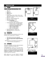
SAFETY PRECAUTIONS
2
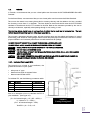
INTRODUCTION
Thank you for purchasing the EUROMAX pellet stove. You are now prepared to burn pellet
in the most efficient, convenient way possible. To achieve the safest, most efficient and
most enjoyable performance from your stove, you must do three things: 1) Install it
properly; 2) Operate it correctly; and 3) Maintain it regularly. The purpose of this manual is
to help you do all three.
PLEASE read this entire manual before installation and use of this pellet fuel-burning room
heater. Failure to follow these instructions could result in property damage, bodily injury or
even death.
Keep this manual handy for future reference.
Your Enerzone EUROMAX has been independently tested to ASTM E1509-04 Standard
Specification for Room Heaters, Pellet Fuel Burning Type, UL 1482-2010 and ULC-S627-00
Standard for Solid Fuel Room Heaters, Oregon Administrative Rules for Mobile Homes (81423-900 through 814-23-909) and Installation as a Stove Heater.
This pellet stove, when installed, must be electrically grounded in accordance with local
codes, or in the absence of local codes, with the National Electrical Code, ANSI/NFPA 70
and CSA-C22.1.
We recommend that our pellet hearth products be installed and serviced by professionals
who are certified in the United States by NFI (National Fireplace Institute®) or in Canada by
WETT (Wood Energy Technology Transfer) or in Quebec by APC (Association des
Professionnels du Chauffage).
The bottom-feed burner system of this appliance is designed and tested specifically for use
only with four different types of pellets: standard wood pellets, 100% bark pellets,
sawdust/hay mix pellets, and switch grass pellets. This appliance is designed for residential
installation according to current national and local building codes as a freestanding room
heater. It is also approved as a mobile home heater. An outside combustion air source is
mandatory.
The stove will not operate using natural draft or without a power source for the blower
systems and fuel feed system and must not be burned with any type of coal.
This stove is designed to provide the optimum proportions of fuel and air to the fire in order
to burn free of smoke and soot. Any blockage of the air supply to or from the stove will
seriously degrade its performance and will be evidence by a smoking exhaust and a
sooting window. For best operation, the ash content of the pellet fuel should be less than
1% and the calorific value approximately 8,200 BTU/LB. Others fuels with a high ash
content will require a higher level of maintenance and cleaning.
Commercial and industrial installations of the Enerzone EUROMAX should not be used since
operational control is often not well managed in these settings.
SAFETY PRECAUTIONS
3
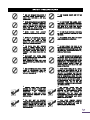
SAFETY PRECAUTIONS
•
DO NOT OPERATE YOUR STOVE IF
YOU SMELL SMOKE COMING FROM IT.
TURN IT OFF, MONITOR IT, AND CALL
YOUR DEALER.
•
NEVER USE GASOLINE, GASOLINE-TYPE
LANTERN FUEL, KEROSENE, CHARCOAL
LIGHTER FLUID, OR SIMILAR LIQUIDS TO
START OR “FRESHEN UP” A FIRE IN THIS
STOVE. KEEP ALL SUCH LIQUIDS WELL
AWAY FROM THE STOVE WHILE IN USE.
•
NEVER
BLOCK
FREE
AIRFLOW
THROUGH THE OPEN VENTS OF THE STOVE.
•
NEVER TRY TO REPAIR OR REPLACE
ANY PART OF THE STOVE UNLESS
INSTRUCTIONS ARE GIVEN IN THIS
MANUAL. ALL OTHER WORK SHOULD BE
DONE BY A TRAINED TECHNICIAN.
•
THE STOVE WILL NOT OPERATE
DURING A POWER OUTAGE. IF AN
OUTAGE DOES OCCUR, CHECK THE STOVE
FOR SMOKE SPILLAGE AND OPEN A
WINDOW IF ANY SMOKE SPILLS INTO THE
ROOM.
•
DISCONNECT THE POWER CORD
BEFORE PERFORMING ANY MAINTENANCE
OR REPAIRS ON THE STOVE.
NOTE: TURNING THE STOVE “OFF” DOES
NOT DISCONNECT ALL POWER FROM THE
STOVE.
•
DO NOT UNPLUG THE STOVE IF YOU
SUSPECT A MALFUNCTION. TURN THE
STOVE OFF, PERIODICALLY INSPECT IT,
AND CALL YOUR DEALER.
•
CONTACT YOUR LOCAL BUILDING
OFFICIALS TO OBTAIN A PERMIT AND
INFORMATION ON ANY INSTALLATION
RESTRICTIONS
OR
INSPECTION
REQUIREMENTS IN YOUR AREA. NOTIFY
YOUR INSURANCE COMPANY OF THIS
STOVE AS WELL.
•
THIS UNIT MUST BE PROPERLY
INSTALLED TO PREVENT THE POSSIBILITY OF
A HOUSE FIRE. THE INSTRUCTIONS MUST BE
STRICTLY ADHERED TO. DO NOT USE
MAKESHIFT METHODS OR COMPROMISE IN
THE INSTALLATION.
•
KEEP FOREIGN OBJECTS OUT OF THE
HOPPER.
•
DO NOT THROW THIS MANUAL AWAY.
THIS MANUAL HAS IMPORTANT OPERATING
AND MAINTENANCE INSTRUCTIONS THAT YOU
WILL NEED AT A LATER TIME. ALWAYS
FOLLOW THE INSTRUCTIONS IN THIS MANUAL.
•
DO NOT PLACE CLOTHING, FURNITURES
OR OTHER FLAMMABLE ITEMS ON OR NEAR
THE STOVE.
•
THE VIEWING DOOR MUST BE CLOSED
AND LATCHED DURING OPERATION.
•
DO NOT OPERATE THE STOVE IF THE
FLAME BECOMES DARK AND SOOTY OR IF
THE BURN POT OVERFILLS WITH PELLETS. TURN
THE STOVE OFF, PERIODICALLY INSPECT IT,
AND CALL YOUR DEALER.
•
DO NOT TOUCH THE HOT SURFACES OF
THE HEATER. CONTACT WITH THE UNIT MAY
CAUSE SKIN BURNS. KEEP CHILDREN AWAY
FROM THE UNIT AND EDUCATE THEM OF THE
DANGERS OF A HIGH TEMPERATURE STOVE.
YOUNG CHILDREN SHOULD ALWAYS BE
SUPERVISED WHEN THEY ARE IN THE SAME
ROOM AS THE STOVE.
•
IF THE STOVE IS INSTALLED IN A ROOM
WITHOUT AIR CONDITIONING, OR IN AN
AREA WHERE THERE IS DIRECT SUNLIGHT ON
THE UNIT, IT IS POSSIBLE THAT THIS CAN
CAUSE THE TEMPERATURE OF THE STOVE TO
RISE TO OPERATIONAL LEVELS. THIS CAN
ACTIVATE ONE OF THE SENSORS WHICH MAY
CAUSE THE STOVE TO START ON ITS OWN. IT
IS RECOMMENDED THAT THE STOVE BE
UNPLUGGED WHEN NOT IN USE FOR
PROLONGED AMOUNTS OF TIME (I.E. DURING
THE SUMMER MONTHS).
•
THE
EXHAUST
SYSTEM
MUST
BE
COMPLETELY AIRTIGHT AND PROPERLY
INSTALLED. ALL VENT CONNECTOR JOINTS
MUST BE SEALED AND FASTENED IN
ACCORDANCE WITH THE PELLET PIPE
MANUFACTURER'S INSTRUCTIONS TO ENSURE
CONSISTENT PERFORMANCE AND AVOID
SMOKE AND ASH SPILLAGE.
•
YOUR
STOVE
REQUIRES
PERIODIC
MAINTENANCE AND CLEANING. FAILURE TO
MAINTAIN YOUR STOVE MAY LEAD TO
SMOKE SPILLAGE IN YOUR HOME.
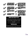
SAFETY PRECAUTIONS
•
ALLOW THE STOVE TO COOL BEFORE
CARRYING OUT ANY MAINTENANCE OR
CLEANING. ASHES MUST BE DISPOSED IN A
METAL CONTAINER WITH A TIGHT LID AND
PLACED ON A NON COMBUSTIBLE SURFACE
WELL AWAY FROM THE HOME STRUCTURE.
•
THIS STOVE MUST BE CONNECTED TO A
STANDARD 120 V., 60 HZ GROUNDED
ELECTRICAL OUTLET. DO NOT USE AN
ADAPTER PLUG OR SEVER THE GROUNDING
PLUG. DO NOT ROUTE THE ELECTRICAL
CORD UNDERNEATH, IN FRONT OF, OR
OVER THE STOVE.
•
THE EXHAUST SYSTEM SHOULD BE
CHECKED, AT A MINIMUM, AT LEAST TWICE
A YEAR FOR ANY BUILD UP OF SOOT OR
CREOSOTE.
•
IT IS MANDATORY TO CONNECT THIS
STOVE TO A 4¨ FRESH AIR INLET TO AVOID
THE RISK OF HOPPER BURN BACK CAUSED
BY NEGATIVE PRESSURE.
4
•
THIS APPLIANCE IS DESIGNED AND TESTED
SPECIFICALLY FOR USE ONLY WITH FOUR
DIFFERENT TYPES OF PELLETS: STANDARD
WOOD PELLETS, 100% BARK PELLETS,
SAWDUST/HAY MIX PELLETS, AND SWITCH
GRASS PELLETS. ANY OTHER TYPE OF FUEL
BURNED IN THIS HEATER WILL VOID THE
WARRANTY AND SAFETY LISTING.
•
THE STOVE MUST BE BOLTED TO THE
FLOOR, HAVE OUTSIDE AIR, AND NOT BE
INSTALLED IN A BEDROOM (PER H.U.D.
REQUIREMENTS).
CHECK
WITH
LOCAL
BUILDING OFFICIALS.
•
THE INFORMATION GIVEN ON THE
CERTIFICATION LABEL AFFIXED TO THE
APPLIANCE
ALWAYS
OVERRIDES
THE
INFORMATION PUBLISHED, IN ANY OTHER
MEDIA (OWNER’S MANUAL, CATALOGUES,
FLYERS, MAGAZINES AND/OR WEB SITES).
•
STOVE BUILDER INTERNATIONAL INC.
GRANTS NO WARRANTY, IMPLIED OR STATED,
FOR THE INSTALLATION OR MAINTENANCE OF
YOUR
STOVE,
AND
ASSUMES
NO
RESPONSIBILITY OF ANY CONSEQUENTIAL
DAMAGE(S).
REGISTER YOUR WARRANTY ONLINE
To receive full warranty coverage, you will need
to show evidence of the date you purchased
your stove. Keep your sales invoice. We also
recommend that you register your warranty
online at:
www.enerzone-intl.com/warrantyregistration.aspx
Registering your warranty online will help us track
rapidly the information we need on your stove.
TABLE OF CONTENTS
SAFETY
1.
1.1.
1.2.
1.3.
1.4.
1.5.
1.6.
1.6.1.
1.6.2.
PRECAUTIONS ............................................................................................................................. 3
INSTALLATION ............................................................................................................................ 7
FEATURES ................................................................................................................................... 7
PREPARATION ............................................................................................................................. 7
CLEARANCES .............................................................................................................................. 7
COMBUSTION AIR SUPPLY ............................................................................................................ 9
ANCHOR THE STOVE .................................................................................................................. 10
VENTING .................................................................................................................................. 11
Equivalent Vent Length (EVL) .................................................................................................... 11
Installation Configurations ......................................................................................................... 12
a)
Vertically with new chimney system ....................................................................................13
b)
Horizontally through wall ....................................................................................................14
c)
Vertically into existing chimney system ................................................................................16
d)
Vertically into existing masonry fireplace .............................................................................16
e)
Installation through side of masonry chimney ......................................................................17
2.
OPERATION.............................................................................................................................. 18
2.1.
PROPER FUEL ............................................................................................................................ 18
2.2.
WHERE TO STORE BAGS OF PELLETS ............................................................................................ 18
2.3.
UNIT CONTROLS........................................................................................................................ 18
2.3.1 LCD User Interface – Operation and Configuration ....................................................................... 19
2.4.
OPERATION TREE ...................................................................................................................... 21
2.5.
SELECTING LANGUAGE ............................................................................................................... 21
2.6.
VIEW STATISTICS........................................................................................................................ 21
2.7.
CHANGING ⁰F TO ⁰C .................................................................................................................. 21
2.8.
CHOOSING THE HEAT SETTING .................................................................................................... 21
2.9.
CHOOSING THE PILOT LAG TIME ................................................................................................. 22
2.10. CHOOSING THE CONVECTION BLOWER SPEED ............................................................................. 22
2.11. CHOOSING MANUAL OR THERMOSTATIC MODE ............................................................................ 22
2.12. OPERATING THE STOVE USING A THERMOSTAT.............................................................................. 22
2.12.1. Thermostat Installation .............................................................................................................. 22
2.13. PRE-START-UP CHECK ................................................................................................................. 23
2.14. FILLING-UP THE AUGER............................................................................................................... 24
2.15. IF YOUR STOVE RUNS OUT OF PELLETS ......................................................................................... 24
2.16. REFUELING ............................................................................................................................... 24
2.17. STARTING THE STOVE ................................................................................................................. 25
2.18. BUILDING A FIRE ....................................................................................................................... 25
2.19. EARLY SIGNS OF AN OVERFIRED STOVE ....................................................................................... 25
2.20. SHUT DOWN PROCEDURE ........................................................................................................... 25
2.21. OPERATING SAFETY PRECAUTIONS .............................................................................................. 25
3.
MAINTENANCE .......................................................................................................................... 27
3.1.
CLEANING THE BURN POT AND THE AIR WASH INLET...................................................................... 27
3.2.
MAINTENANCE OF THE COMBUSTION CHAMBER, HEAT EXCHANGERS AND BLOWER HOUSING ............ 28
3.3.
MAINTENANCE OF THE HEAT EXCHANGERS AND BLOWER HOUSING ................................................ 28
3.4.
VENTING SYSTEM MAINTENANCE ................................................................................................. 29
3.4.1. Dealing with a Chimney Fire ...................................................................................................... 29
3.4.2. Soot and Flyash – Formation and need for removal ..................................................................... 30
3.5.
ASH REMOVAL .......................................................................................................................... 30
3.5.1. Ash Disposal and Ash Vacuum Use ............................................................................................ 30
3.6.
DOOR ADJUSTMENT .................................................................................................................. 31
3.7.
DOOR GASKET MAINTENANCE .................................................................................................... 31
3.8.
GLASS CARE ............................................................................................................................. 32
3.9.
REMOVAL AND REPLACEMENT OF BROKEN DOOR GLASS .............................................................. 32
3.10. REMOVAL AND REPLACEMENT OF GASKETS .................................................................................. 35
3.11. RECOMMENDED MAINTENANCE SCHEDULE ................................................................................... 40
4.
TROUBLESHOOTING GUIDE ........................................................................................................ 41
5.
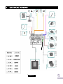
ELECTRICAL DIAGRAM ............................................................................................................... 47
5.1
FUSE ACCESS:............................................................................................................................ 48
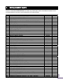
6.
REPLACEMENT PARTS ................................................................................................................. 49
APPENDIX A ......................................................................................................................................... 52
APPENDIX B ......................................................................................................................................... 53
APPENDIX C ......................................................................................................................................... 54
ENERZONE LIMITED LIFETIME WARRANTY ................................................................................................. 56
INSTALLATION
1.
1.1.
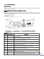
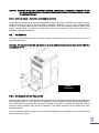
FEATURES
ENERZONE EUROMAX FREESTANDING PELLET STOVE
•
•
•
•
•
•
Width: 24”
Height: 41”
Depth: 28”
Weight: 375 lbs.
Flue size: 4”
Hopper Capacity: Up to 125 lbs. (This can vary
•
•
•
•
EPA status: < 4.5 g/h
Burn rate: 1.3 lbs to 8.5 lbs. per hour
BTU range: 10,500 to 70,000
Electrical consumption:
o 5 Amps lighting cycle
o 2.5 Amps. continuous duty
Control board fuses: Main: 7.5A-250V fastblow
o Convection blower: 5A-250V fastblow
o Combustion blower: 3A-250V fastblow
o Exhaust blower: 3A-250V fastblow
o Auger 1: 3A-250V fastblow
o Auger 2: 3A-250V fastblow
o Ignitor : 5A-250V fastblow
Electrical requirement: 120VAC 15A
Approved installations: mobile home or
conventional
•
•
•
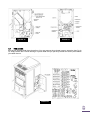
1.2.
depending on pellet size, length, and diameter)
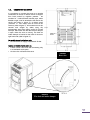
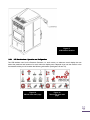
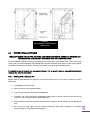
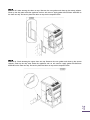
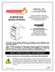
PREPARATION
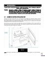
Factory packaging must be removed, and some minor
assembly work is required prior to installation:
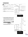
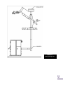
FIGURE 1
Back wall installation
FIGURE 2
Corner installation
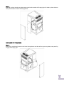
•
•
•
The handle and door must be adjusted;
The stove must be leveled using threaded legs;
The door overlay must be installed on the door
frame
The LCD control must be installed on the back (left or
right) of the stove; (see appendix C )
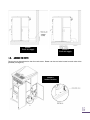
1.3.
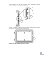
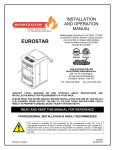
CLEARANCES
The Enerzone EUROMAX has been tested and listed for
installation in residential and mobile home
FLOOR PROTECTION: minimum to 6” in the front and 6”
on each side of the door opening. The stove must be
placed on a continuous (grouted joints) noncombustible
material such as ceramic tile, cement board, brick, 3/8”
millboard or equivalent, or other approved or listed
material suited for floor protection.
NOTE: ceramic tile, or any tile, requires a continuous
sheet beneath to prevent the possibility of embers
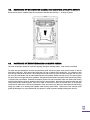
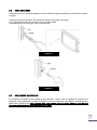
Door opening
FIGURE 3
Floor protection
falling through to the combustible floor if cracks or
separation should occur in the finished surface, this
would include floor protection for built-in raised hearths.
Check local codes for approved alternatives.
Clearances are measured from the sides, back, or face
(door opening). For ceiling clearance refer to figure 4.
Clearances may only be reduced by means approved
by the regulatory authority.
NOTE: In order to allow the LCD support to move freely
and fully extend, you should allow a minimum of
4''clearance in a back installation (Figure 1) or 6 ¼''
from the corners in a corner installation (Figure 2).
However, if you wish to install the appliance with
minimum clearances it is possible to install the LCD
control box elsewhere but within the maximum length
of the Telco wire provided.
CAUTION: DO NOT USE MAKESHIFT MATERIALS OR
COMPROMISES IN THE INSTALLATION OF THIS
UNIT.
FIGURE 4
Ceiling clearance
CAUTION: INSTALL VENT WITH CLEARANCES SPECIFIED BY
THE VENT MANUFACTURER.
This heating unit must serve as a supplementary heat
source. An alternative heat source should be available
in the home if needed. The manufacturer cannot be
responsible for additional heating costs associated with
the use of an alternative heat source.
It is highly recommended that the user buys this product
from a retailer who can provide installation and
maintenance advices.
We recommend leaving 24’’ on each sides of the
appliance in order to facilitate access for maintenance.
FLOOR PROTECTION
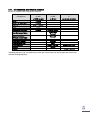
CLEARANCES TO COMBUSTIBLES
A
B
C
D
CANADA
USA
2’’ (55 mm)
6’’ (155 mm)
2’’ (55 mm)
3’’ (80 mm)
2’’ (55 mm)
6’’ (155 mm)
2’’ (55 mm)
3’’ (80 mm)
E
F
G
H
CANADA
USA
18’’ (460 mm)
N/A (USA only)
8’’ (205 mm)
8’’ (205 mm)
6’’ (155 mm)
6’’ (155 mm)
N/A (Canada only)
N/A (Canada only)
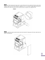
1.4.
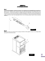
COMBUSTION AIR SUPPLY
It is mandatory to connect this stove to an outside
combustion air source to reduce the risk of hopper
burn back caused by negative pressure.
An
insulated 4” inside diameter metallic pipe, either
flexible or rigid, must be attached to the inlet at the
stove’s rear (refer to figure 5). A rodent guard
(minimum ¼” wire mesh) must be used at the
terminus (refer to figure 7). All connections must be
secured and airtight by either using the
appropriately sized hose clamp and/or UL-181-AP
foil tape. Also make sure that the fresh air damper
is open while the stove is running. The fresh air
intake damper is located at the back of the stove
right hand side (refer to figure 6.).
For mobile home installations only:
• No combustion air supply may exceed 10 feet.
Sources of Outside Combustion Air:
• A hole in floor near stove rear terminating only
in a ventilated crawl space.
• A hole in the wall behind the stove.
FIGURE 5
Rear view
FIGURE 6.
The fresh air intake damper
FIGURE 7
Fresh air supply
FIGURE 8
Fresh air supply
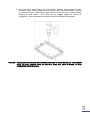
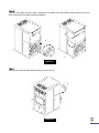
1.5.
ANCHOR THE STOVE
The stove must be anchored to the floor with screws. Please use the two holes located on each side of the
pedestal (see figure 9.)
FIGURE 9
Anchor location
1.6.
VENTING
In Canada, we recommend that you use a listed pellet vent that meets the ULC S-609-M89/ORD C441-M90
Standard.
For the United States, we recommend that you use a listed pellet vent that meets the UL-641Standard.
This unit can be vented in an existing factory-built or masonry chimney with the addition of a liner, provided
the chimney is more than 4” in diameter. The liner should be listed and should meet the ULC S-635/640
standard in Canada and the UL-1777 standard in the USA. Refer to the instructions provided by the vent or
chimney manufacturer, especially when passing through a wall, ceiling, or roof.
Your venting system should have at least one foot of vertical rise for each foot of horizontal run. The total
vertical rise should never be less than 3 feet (see Appendix A).
This unit uses a pressurized exhaust system. All vent connector joints must be sealed and fastened. If vented
horizontally, joints should be made gastight. Please consult the pellet pipe manufacturer’s instruction to ensure
proper installation and consistent performance to avoid smoke and ash spillage.
DO NOT CONNECT THIS UNIT TO A CHIMNEY FLUE SERVING ANOTHER APPLIANCE.
DO NOT INSTALL A FLUE DAMPER IN THE EXHAUST VENTING SYSTEM OF THIS UNIT.
WARNING: INSTALL VENT AT CLEARANCES SPECIFIED BY THE VENT MANUFACTURER.
WARNING: DO NOT INSTALL IN SLEEPING ROOM
CAUTION: THE STRUCTURAL INTEGRITY OF THE MANUFACTURED HOME FLOOR, WALL, AND CEILING/ROOF
MUST BE MAINTAINED
CAUTION: THE CHIMNEY CONNECTOR SHALL NOT PASS TROUGH AN ATTIC OR ROOF SPACE, CLOSET OR
SIMILAR CONCEALED SPACES, OR FLOORS, OR CEILINGS.
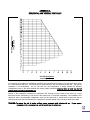
1.6.1. Equivalent Vent Length (EVL)
The longer the run of pipe in your installation, the
greater the restriction in your system.
•
•
•
Always use 4” pipe
Horizontal runs shall not exceed 9 feet.
Never exceed 30 feet of EVL..
To calculate EVL, use the following conversions table:
Qty
Type of pipe
1
90° elbow or “T”
EVL equivalent(ft)
5
1
45° elbow
3
1 ft
Horizontal pipe run
1 ft
Vertical pipe run
1
0.5
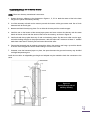
Here is an example on how to calculate the EVL of
your installation. (See Figure 10):
(3 x 4’ of vertical length = 12’ x 0.5 = 6 EVL) +
(1 x elbow or "T" = 5 EVL) +
(2 x 1’ of horizontal length = 2 EVL)
Total EVL = (6 + 5 +2) = 13.
FIGURE 10
Venting through wall
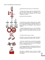
1.6.2. Installation Configurations
Termination Location
Termination should not be located so that hot exhaust gases can be a hazard. They can reach temperatures
of 500 ºF and cause serious burns.
CAUTION: TERMINATION COLLAR (SPARK ARRESTER) IS MANDATORY.
Refer to NFPA 211 (USA) or CSA B365 (Canada) for rules for the distance of exit terminal from windows and
openings. The exit terminal of a mechanical draft system, other than a direct vent appliance shall be located
in accordance with the following.
Permitted Termination Location
Canada:
Letter
Min. clearances
Description
A
12’’ (30 cm)
Clearances above grade level or any adjacent surface that might support
snow, ice, or debris
B
39’’ (100 cm)
Clearance to window or door that may be opened
F
39’’ (100 cm)
Clearance to corner or adjacent wall
H
39’’ (100 cm)
I
72’’ (183 cm)
J
39’’ (100 cm)
Clearance to the combustion air inlet to any other appliance
K
72’’ (183 cm)
Clearance to a mechanical air supply inlet
L
84’’ (213 cm)
Clearance above paved side-walk or a paved driveway located on public
property
39’’ (100 cm)
Clearance to property boundary
Not to be installed above a meter/regulator assembly within 39" (100 cm)
horizontally from the vertical center-line of the regulator and for 15’ vertically
Clearance to gas service regulator vent outlet or within 39’’ (100 cm) of an
oil tank vent or an oil tank fill inlet
A vent shall not terminate underneath a veranda, porch, or deck
United States:
•
•
Not Less than 36’’ (91 cm) above any forced air inlet located within 10 feet (305 cm);
Not Less than 48’’ (122 cm) below and horizontally from, or one foot (30 cm) above, any door, window
or gravity air inlet into any building;
Not Less than 24’’ (61 cm) from an adjacent building and not less than 84’’ (213 cm) above grade when
located adjacent to a public walkway.
Cannot be located less than 12 inches (300mm) above grade.
Cannot be located above a gas meter/regulator within 3 feet (900mm) horizontally of the vertical center
line of the regulator.
Not within 6 feet (1.8 meters) of a gas service regulator vent outlet.
Other restrictions may apply. See NFPA 211 for further information.
•
•
•
•
•
a) Vertically with new chimney system
(Refer to Figure 13)
NOTE: Follow vent chimney manufacturer’s instructions.
OPTION: To achieve a centered vertical installation, a 45º elbow and a clean-out tee can be used to offset
the pipe from the exhaust outlet to the rear center of the stove.
OPTION: Install vent elbow in place of clean-out tee. Locate stove. Drop plumb bob to center of tee outlet,
mark point on ceiling. Install ceiling support and vent pipe per vent manufacturer’s instructions.
1. Always maintain 3” clearance from combustible materials. When passing through additional floors or
ceilings, always install firestop spacer.
2. After lining up for hole in roof, cut either a round or square hole in roof, always 3” larger all the way
around pipe. Install upper edge and sides of flashing under roofing materials, nail to the roof along
upper edge. Do not nail lower edge. Seal nail heads with flexible waterproof sealant.
3.
Apply flexible, waterproof sealant where the storm collar meets the vent. Slide storm collar down until it
sits on the flashing. Seal and install cap. Mobile home installations must use a spark arrester.
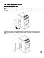
b) Horizontally through wall
(Refer to figures 11 or 12)
NOTE:
Follow
instructions.
Vent
chimney
manufacturer’s
1. Position stove, adhering to clearances shown in
Figures 1, 2, 3 & 4.
2. Locate position of hole in wall; directly behind
stove exhaust vent (refer to figure 5).
3. Always maintain 3” clearance from combustible
materials.
4. Install vent wall thimble per vent manufacturer’s
instructions.
FIGURE 11
Venting through wall
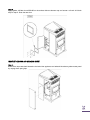
5. Attach enough piping to penetrate and extend
at least 6 inches beyond the exterior wall. There
should always be at least one foot of vertical rise
for each foot of horizontal run (see Appendix A).
At least 3 feet of vertical rise are needed in all
cases. A longer vertical rise will favour a better
exhaust.
6. To reduce the risk of smoke spillage, never
terminate with a horizontal run. If your system
terminates with a horizontal run, add at least 3
feet of vertical rise (see Appendix A).
7. Attach cap and seal outside wall thimbles with
non-hardening waterproof mastic.
FIGURE 12
Venting through wall
Basement installation
FIGURE 13
Venting through roof
c) Vertically into existing chimney system
(Refer to Figure 14)
As an alternative, 4” vent can be run inside existing chimney to termination (Figure 14). This is the preferred
method.
Follow guidelines for equivalent vent length.
FIGURE 14
Venting through
existing chimney
d)
Vertically into existing masonry fireplace
(Refer to figure 15)
NOTE:
Follow
instructions.
vent
chimney
manufacturer’s
1. Have the masonry chimney inspected by a
qualified chimney sweep or installer to
determine its structural condition.
2. You will need a pipe length equal to the
chimney height from the hearth. If outside
combustion air is to be used, you will need a
pipe length equal to the chimney height plus 18
inches.
3. Install a blanking plate and the chimney pipe,
and if used the outside air pipe, as shown in
Figure 15.
4. Attach the adapter, a section of pipe and clean
out tee, making sure the clean out tee is
centered in the chimney flue area. Use RTV,
metallic tape, and a minimum of three selftaping screws at all joint connections to ensure a
tight seal.
Figure 15
Venting through masonry
chimney
5. Position the stove, adhering to the clearances in
Figures 1, 2, 3 & 4.
6. Measure and build chimney top plate. Cut out holes for chimney pipe, and if used the outside air pipe.
Install and seal with non-hardening mastic to prevent water leakage. Install vent cap.
e) Installation through side of masonry chimney
(Refer to figure 16)
NOTE: Follow vent chimney manufacturer’s instructions.
1. Position the stove, adhering to the clearances in Figures 1, 2, 3 & 4. Mark the center of the hole where
the pipe is to pierce the masonry chimney.
2. It will be necessary to break out the masonry around the location of the pipe center mark. Use a 5-inch
diameter hole for 4-inch pipe.
3. Measure and build chimney top plate. Cut out holes for chimney and the outside air pipe.
4. Install the tee on the bottom of the vertical pipe system and lower it down the chimney until the center
branch of the tee is level with the center of the hole in the masonry, as shown in Figure 16.
5. Install and seal the top plate from step 3 with non-hardening mastic. Slip the storm collar over the pipe,
and while holding the pipe at the proper elevation, affix the collar with a minimum of three ¼” stainless
steel sheet metal screws. Seal all joints and seams around the collar.
6. Connect the horizontal pipe by pushing it through the hole in the masonry and lining it up with the branch
in the tee. Push the pipe into the tee while twisting it to lock it into the tee.
7. If desired, once the horizontal pipe is in place, the space between the pipe and masonry may be filled
with high-temperature grout.
Install the trim collar. An adjustable pipe length and adapter may be needed to finish the connection to the
stove.
Figure 16
Venting through side of
masonry chimney
2.
OPERATION
2.1.
PROPER FUEL
THIS STOVE IS APPROVED FOR BURNING four different types of pellets: standard wood pellets, 100% bark
pellets, sawdust/hay mix pellets, and switch grass pellets! Each type of pellet has its properties and will burn
differently.
The ash produced can also vary greatly. Factory-approved pellets are those ¼” or 5/16” in diameter and not
over 1” long. Longer or thicker pellets sometimes bridge the auger flights, which prevents proper pellet feed.
Burning other types of pellets is not permitted. It will violate the building codes for which the stove has been
approved and will void all warranties. The different types of pellets that have been tested in the Enerzone
EUROMAX were made of the following types of biomass:
Wood pellets
Wood pellets, whether made of hard or soft wood, are easy to burn. The pellets used are the same type as
the ones used in most pellet stoves. They should produce a fairly small quantity of ash.
Wood and hay pellets
Pellets made of wood and hay will produce more ash than straight wood pellets. The wood and hay pellets
that have been tested in your EUROMAX consisted of 1/3 hay and 2/3 wood. Make sure that any wood and
hay pellets you put in your EUROMAX respect that mix (+/- 10%).
Bark pellets
100% bark pellets produce a hard crust that will be pushed into the ash drawer. Their ash content is very
high. If you burn 100% bark pellets, make sure that the crust forming in front of the burn pot breaks and falls
into the ash drawer. Ignition may be a bit more difficult and it is possible that the stove needs a second
ignition cycle to properly light the bark pellets.
Switchgrass pellets
The ash content of switch grass pellets may vary depending on when this type of biomass is harvested. Switch
grass will burn very clean. A crust will form in front of the burn pot. It should break easily and fall into the ash
drawer. The crust is light and friable. It will occupy quite a bit of volume into the ash drawer. For this reason,
if you are not present to empty the ash drawer, you should only fill 50% of the hopper.
2.2.
WHERE TO STORE BAGS OF PELLETS
We recommend that you store your bags of pellets in a dry and well ventilated area if possible. Using dry
pellets will increase the performance of your stove. You may want to have a bag or two in the same room
as your stove for refuelling but make sure to respect the minimum clearances for combustible materials.
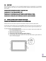
2.3.
UNIT CONTROLS
The Enerzone Euromax use a LCD screen, the latest technology in control devices. This LCD interface is located
at the back on the right-hand side of the EUROMAX (see figure 17). The blowers and automatic fuel supply
are controlled from this panel. The control panel functions are as follows.
Figure 17
LCD Interface location
2.3.1
LCD User Interface – Operation and Configuration
The LCD interface used on the Enerzone Euromax is a touch screen, an electronic visual display that can
detect the presence and location of a touch within the display area. Depends if you use the manual or the
thermostatic mode you will visualize the following information (see figures 18 and 19):
Figure 18
Manual mode main page
Figure 19
Thermostat mode main
page
Here is a brief description of each bottom:
= Indicates that the stove status is on manual mode
= Indicates that the stove status is on thermostat mode.
The red waves indicate that the thermostat is on
demand. The waves will disappear once the desired
temperature is reached.
,
= Indicates the flue temperature
,
,
,
,
,
,
= Indicates the heat setting. Starting from
flame to the biggest flame, the respective
to 6. Pressing on the desired heat level
change the color of the flame to red
activation.
the smallest
levels are 1
(flame) will
to show its
= Indicates whether the stove is on or off. If the flame is
shown in the middle of the circle, the stove is on. If the
flame is not shown in the middle of the circle, the stove
is off.
= This button leads to the menu screen
This button is used to fill the auger. When the auger is
running the auger button is going to show a red arrow.
,
= This button indicates if the convection blower speed
control is on or off. If the fan is not surrounded by
arrows, the speed control is off. If the fan is surrounded
by arrows, the speed control is on.
,
= The hourglass indicates how long the pilot will be on
before shutting down the unit. The setting chosen by the
user appears under the hourglass.
=This button is displayed when you have a warning
message from your unit. Just press the button to read
the message.
2.4.
OPERATION TREE
Figure 20
Operation Tree
2.5.
SELECTING LANGUAGE
You can choose between English and French. In order to change the language, refer to the operation tree at
the beginning of this section.
2.6.
VIEW STATISTICS
Numerous statistics can be viewed, such as the stove run time (i.e. the number of hours the stove has
operated since it was first used). In order to view statistics, refer to the operation tree at the beginning of this
section.
2.7.
CHANGING ⁰F TO ⁰C
You can choose between oF and oC. In order to change from oF to oC and vice-versa, refer to the operation
tree at the beginning of this section.
2.8.
CHOOSING THE HEAT SETTING
Your Euromax has an input starting at 10,500 BTU which can reach up to 70,000 BTU. There are six heat
levels to choose from. In order to change the heat level, pressing on the desired heat level. The flame icon
will change the color of the flame to red to show its activation.
2.9.
CHOOSING THE PILOT LAG TIME
It is possible to change the setting of your unit such that if the thermostat does not call for heat after 45
minutes, the unit will remain at the lowest heat setting (#1) without shutting down (this is the PILOT ON
mode). The stove will remain at the lowest heat level until the thermostat calls for heat again. It is also
possible that the unit shuts down as soon as the thermostat stops calling for heat. This mode is called “PILOT
OFF”. Also you can set the lag time to 30, 45 or 60 minutes. If you prefer that your unit runs following one
of these logics, you need to change the setting to PILOT ON or PILOT OFF. In order to change the pilot lag
time, refer to the operation tree at the beginning of this section.
2.10. CHOOSING THE CONVECTION BLOWER SPEED
When you press the convection blower speed button, a screen appears with a cursor to adjust the fan speed
as desired;
Figure 21
Fan Speed Control
2.11. CHOOSING MANUAL OR THERMOSTATIC MODE
In the manual mode, your stove will run continuously at the feed rate selected until the stove runs out of
pellets.
When set in thermostatic mode, the stove will automatically run at the heat level selected until the set room
temperature is reached. When that occurs, the stove will switch to heat setting #1 (lowest), which is the pilot
mode, until the thermostat calls for heat again. When the thermostat calls for heat again, the stove will
increase its feed rate to match the heat setting selected, refer to the operation tree at the beginning of this
section.
2.12. OPERATING THE STOVE USING A
THERMOSTAT
A thermostat may help you maintain a constant
house temperature automatically. A low voltage
thermostat is required. A fixed wall mount or hand
held model can be used. The control panel can be
set up three ways to operate your stove in
thermostatic mode.
2.12.1. Thermostat Installation
•
Unplug the stove from the power outlet.
•
Connect two thermostat wires to the terminal
block located on the lower right side of the back
of the stove. To do so, loosen the two screws
and insert the wires in the terminals. Tighten the
two screws. (See figure 22)
FIGURE 22
Rear view
•
If you are using a wireless wall thermostat or a hand held thermostatic remote control, you can locate the
receiver behind the stove’s back panel, on the right end side, just below the terminal block. Most
receivers are already equipped with quick-connect terminals. Simply unplug the PC board wires
connected to the back of the terminal block and connect them directly with the receiver’s terminals.
Location of the thermostat is very important to obtain the best comfort and efficiency from your EUROMAX.
The thermostat should be mounted 50 inches from the floor on a wall located 15 to 20 feet from the
stove. You should avoid an installation directly in front of the stove to avoid cycling.(See figure 23)
Figure 23
Thermostat Location
N.B.: It is possible to change the setting of your unit such that if the thermostat does not call for heat after 45
minutes(lag time), the unit will remain at the lowest heat level (#1) but will not shut down (this is the PILOT
ON mode). The stove will remain at the lowest heat level until the thermostat calls for heat again. In the
other way, it is also possible that the unit shuts down as soon as the thermostat stops calling for heat. This
mode is called “PILOT OFF”. If you prefer that your unit runs following one of these logics PILOT ON or PILOT
OFF, you need to change the setting to ALWAYS ON or PILOT OFF. According to your preferences, you can
also be able to set the pilot lag time to 30, 45 or 60 minutes. In order to change the pilot lag time, refer to
the operation tree at the beginning of this section.
NOTE: When in thermostatic mode:
•
You should not operate the manual control or play with the temperature setting.
•
YOUR THERMOSTAT SHOULD BE INSTALLED BY AN AUTHORIZED DEALER OR SERVICE PERSON.
2.13. PRE-START-UP CHECK
Remove burn pot, making sure it is clean and none of the air holes are plugged. Clean the firebox, and then
reinstall burn pot. Clean door glass if necessary (a dry cloth or paper towel is usually sufficient). Never use
abrasive cleaners on the glass or door. Check fuel in the hopper, and refill if necessary. Make sure that the
fresh air inlet damper is open.
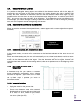
2.14. FILLING-UP THE AUGER
When the stove runs out of pellets, it empties the auger housing. In order to start the stove again, you need
to fill the auger to bring pellets to the burn pot for ignition. This process takes approximately 1 minute and a
function has been programmed on the LCD interface. In order to fill the auger, push the auger button. When
that button is pressed, a 3 option window appears:
Figure 24
Auger button options
The FEED AND START button is used when you start the stove after the hopper run out of pellet. The
auger will run during 1 minute then the stove will start automatically an ignition sequence.
The PURGE SCREW button is used to empty the auger at the end of the season, the auger will run
during 4 minutes.
The ADD PELLETS button is used to add more pellet in the burn pot, the auger will run for 20
seconds.
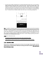
2.15. IF YOUR STOVE RUNS OUT OF PELLETS
If your stove runs out of pellets, the fire goes out and the auger motor and blowers will run until the stove
cools down. This will take a few minutes. After the stove’s components stop running, a warning message “NO
FUEL” will appear on the LCD display.
To restart the stove, press the “RESET” button, refill the hopper, and press the
AND START button.
button followed by FEED
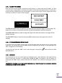
2.16. REFUELING
We recommend that you not let the hopper go completely empty. Upon reloading, if the hopper lid stays
open for more than 3 minutes, a warning code ‘’HOPPER LID OPEN’’ will appear on the LCD display. To
restart, press the “RESET” button, and then press the round “ON/OFF” icon on the main status page to start the
unit.
KEEP HOPPER LID CLOSED AT ALL TIMES EXCEPT WHEN REFILLING. THE HOPPER MAY BE FILLED WHILE THE STOVE
IS OPERATING. DO NOT OVERFILL HOPPER.
2.17. STARTING THE STOVE
Before you start your stove, fill hopper and clean burn pot. Once the hopper is full of pellets, the auger is
filled, and the firebox door is closed, you can start the stove. In order to start the stove, select the desired
mode (manual or thermostatic) then simply press the round “on/off” icon on the main status page.
If fire doesn’t start in 35 minutes, a warning code
troubleshooting section for more details.
will appear. Refer to
2.18. BUILDING A FIRE
Never use a grate or other means of supporting the fuel. Use only the Enerzone Euromax approved burn pot.
NOTE: During the first few fires, your stove will emit an odor and a small amount of fumes as the high
temperature paint cures or becomes seasoned to the metal. Maintaining smaller fires will minimize this. Avoid
placing items on stovetop during this period because paint could be affected. Make sure the room is wellventilated. Open windows. Odors and fumes released during this process are unpleasant but they are not
toxic.
2.19. EARLY SIGNS OF AN OVERFIRED STOVE
If you see a lazy, very high orange flame inside the firebox, it may be a sign that your stove is overfired and
getting too hot. Under normal conditions, the flame should be about 12 inches high and it should be lively.
It should have a bright, yellow color. Too much restriction in the venting system and a blocked heat
exchanger are the primary causes of an overfired stove. If the stove becomes too hot, it will activate the
thermistor located on the exhaust box beside the exhaust blower. If this occurs, a “UNIT OVERHEAT” code will
appear on the LCD display. If you obtain a “UNIT OVERHEAT” code, it is a sign that your stove is getting
dangerously hot. You need to clean the heat exchanger and verify the venting system. If you get a “UNIT
OVERHEAT” code again, call your dealer.
2.20. SHUT DOWN PROCEDURE
Turning your stove off is a matter of pressing the round “ON/OFF” icon on the main status page. The little
flame at the center of the icon will disappear when the stove is turned off. The blowers will continue to
operate while the stove is cooling down.
2.21. OPERATING SAFETY PRECAUTIONS
PLEASE READ THIS!
a. If you notice a smoldering fire (burnpot full but no visible flame) AND a heavy smoke buildup in firebox,
immediately TURN OFF the stove, but DO NOT unplug it. Do not open the door. Make sure that the fresh
air damper is open and do not tamper with any controls on the stove. Wait until smoke inside the
firebox clears and blowers shut down. Do as instructed in “PRE-START-UP CHECK” and “LIGHTHING
PROCEDURE”, then attempt to restart the fire. If the problem persists, contact your dealer. Please note
that smoke build-up during ignition may occur. Smoke can accumulate in the firebox for a few seconds
just before the igniter is hot enough to fire-up the pellets in the burn pot. This is normal. As soon as there
is fire in the burn pot, smoke will disappear.
b. DO NOT STORE OR USE FLAMMABLE LIQUIDS, ESPECIALLY GASOLINE, IN THE VICINITY OF YOUR ENERZONE
STOVE. NEVER USE A GAS OR PROPANE TORCH, GASOLINE, GASOLINE-TYPE LANTERN FUEL, KEROSENE,
CHARCOAL LIGHTER FLUID OR SIMILAR FLUIDS TO START OR “FRESHEN UP” A FIRE IN THIS HEATER.
c.
WARNING: DO NOT OVERFIRE THIS STOVE. This may cause serious damage to your stove and void your
warranty. It also may create a fire hazard in your home. IF ANY EXTERNAL PART OF THE UNIT BEGINS TO
GLOW, YOU ARE OVERFIRING. Immediately press the “MODE” switch on the control panel, until reaching
the ‘OFF’ position. DO NOT UNPLUG YOUR STOVE. If you leave your house and your stove is not
connected to a thermostat or a fresh air supply, do not leave it at the maximum setting. If the ambient
air in a confined room becomes too hot, the stove may overheat and the thermal protection on the
combustion motor, exhaust motor or auger motor may be activated. This will cause one of the motors to
stop and a warning code may appear. Also, the thermistor may reach its maximum limit. If this
happens, the stove will automatically reduce the feeding rate until the thermistor temperature has
decreased.
d. KEEP ALL LOOSE OR MOVEABLE HOUSEHOLD COMBUSTIBLES, SUCH AS FURNITURE, DRAPES, TOYS, ETC. AT
LEAST THREE FEET FROM THE OPERATING STOVE.
e. Maintain proper ventilation. It is important that adequate oxygen be supplied to the fire for proper
combustion. During the winter season, make sure that the fresh air intake is free of any ice as this will
starve the fire of air and prevent the proper operation of the stove. YOUR STOVE MUST BE CONNECTED
TO A 4” FRESH AIR KIT. Always make sure that the fresh air intake damper is fully open when the stove is
in use.
f.
The stove exhaust fan produces a negative pressure in the room. It draws air from the inside to the
outside. In the same way, other appliances can also create a bigger negative pressure. In this case, as
the air naturally flows from high pressure point to low pressure point, the bigger negative pressure may
draw the smoke from the inside of the stove into the room. The stove can also affect other ventilation
appliances, causing the same effect to them.
g. Not following the instructions contents of his manual may cause smoke spillage into the room and other
potential hazards. It is always recommended to install strategically placed smoke detectors and to have
a fire extinguisher in a convenient location.
h. Do not open the stove door when operating unless necessary. This will create a dirty, inefficient burn and
could allow smoke spillage or sparks to escape.
i.
Do not open the ash drawer access panel when operating unless necessary. This will create a dirty,
inefficient burn and could allow smoke spillage or sparks to escape.
j.
Do not permit operation by young children or those unfamiliar with stove’s operation.
k.
Do not service or clean this appliance without disconnecting the power cord.
l.
If the stove is installed in a room without air conditioning, or in an area where direct sunlight can shine on
the unit, it is possible this can cause the temperature of the stove to rise to operational levels; one of the
sensors could then make the blowers start on their own. It is recommended that the stove be unplugged
when not in use for extended periods of time (i.e. during the summer months).
m. Burning any solid fuels generates carbon monoxide in low concentration. This gas is evacuated by the
exhaust venting system. In higher concentrations, carbon monoxide is toxic and may cause death. To
prevent this, ensure that your venting system is gastight.
n. Use only approved fuels in this stove. Some other fuels may be highly volatile, which may cause more
embers to enter the exhaust venting system causing a hazardous situation. Other fuels type, such as
charcoal, can create a higher concentration of carbon monoxide leading to potential poisoning.
3.
MAINTENANCE
FAILURE TO CLEAN AND MAINTAIN THIS UNIT AS INDICATED CAN RESULT IN POOR PERFORMANCE AND SAFETY
HAZARDS. NEVER CLEAN WHEN HOT.
WARNING:
3.1.
THE USE OF A DOMESTIC, CENTRAL OR COMMERCIAL VACUUM CLEANER TO PERFORM THE
MAINTENANCE OF YOUR PELLET STOVE IS NOT RECOMMENDED. ASH PARTICLES ARE SO FINE
THAT IT CAN DAMAGE THE MOTOR OF SUCH VACUUM CLEANERS. MOREOVER, EMBERS THAT ARE
STILL HOT MAY CATCH FIRE IN THE USE OF AN ASH VACUUM. THE MODEL CHEETAH II (AC02580)
ASH VACCUM IS SPECIALLY DESIGNED FOR THIS USE AND IS HIGHLY RECOMMENDED.
CLEANING THE BURN POT AND THE AIR WASH INLET
The burn pot should be kept clean and its ports should not be clogged with combustion residues. Cleaning
the burn pot is simple. To do so, you may use a scraper, a brush or release the clip in front of the burn pot.
Then, remove the burn pot by lifting and pulling it out. Once the burn pot is removed you should clean
thoroughly inside the burn pot mount with an ash vacuum.
Once the burn pot is clean, vacuum the ashes that may have accumulated in the air wash inlet slot (A)
between the bottom glass retainer and the glass. This will allow an optimum air flow along the inside portion
of the glass and prevents the glass from sooting-up.
FIGURE 25
Burn Pot
NOTE: Inspect burn pot periodically to see that the holes have not become plugged. If so, clean thoroughly.
3.2.
MAINTENANCE OF THE COMBUSTION CHAMBER, HEAT EXCHANGERS AND BLOWER HOUSING
Remove and clean the baffle inside the combustion chamber after burning +/- 10 bags of pellets.
3.3.
MAINTENANCE OF THE HEAT EXCHANGERS AND BLOWER HOUSING
The heat exchangers should be inspected regularly during the heating season. Easy access is provided:
To access the heat exchangers, remove the decorative panel and the air jacket access panel located on the left
hand side of the stove. Then, remove the three clean out trap to perform the maintenance. It is important to start
from the top and finish at the bottom. Use a scraper and an ash vacuum to clean the heat exchanger. The use of an
ash vac is the most efficient way to collect ashes that have accumulated. Please note that you do not need to repeat
the same steps on the right side of the appliance. The right hand side needs to be opened and cleaned only if there
is excessive ash accumulation. Exhausted combustion product may also accumulate within the exhaust fan housing
and block the pressure switch tap located on the blower’s cleanout panel. Disconnect the pressure switch hose and
remove the blower’s cleanout panel. Then use a mesh or wire brush to clean the tap then blow in the pressure
switch hose to make sure it is free of any obstruction. Clean and vacuum any build-up in the exhaust blower housing
being very careful not to damage the impellers while cleaning each blades. Should one of the cleanout panel
gasket be damaged, it is very important that you replace it in order to prevent leakage of flue gases and soot
FIGURE 26
Cleanout panel and Pressure
tap location
3.4.
VENTING SYSTEM MAINTENANCE
REGULARLY EXAMINE THE FLUE PIPES, THE JOINTS, AND THE SEALING TRIMS TO ENSURE THAT THE SMOKE AND
THE COMBUSTION GASES ARE NOT TRANSPORTED INTO THE AIR DUCTING SYSTEM.
The most efficient method to sweep the venting system is by using a 4-inch pellet brush. Brush downwards
so ash, soot and creosote residues will come off the inner surface and fall at the bottom of the venting system
where they can be removed easily. The chimney must be in good condition and kept clean.
If a significant layer of creosote has accumulated (3mm / 1/8” or more), it must be removed immediately to
eliminate the risk of a chimney fire.
3.4.1. Dealing with a Chimney Fire
Regular chimney maintenance and inspection can prevent chimney fires. If you have a chimney fire, follow
these steps:
1. Immediately turn off the stove;
2. Alert your family of the possible danger;
3. If you require assistance, alert your fire department;
4. If possible, use a dry chemical fire extinguisher, baking soda or sand to control the fire. Do not use
water as it may cause a dangerous steam explosion;
5. Check outside to ensure that sparks and hot embers coming out of the chimney are not igniting the
roof;
6. Do not use the stove again until your chimney and stove have been inspected by a qualified
chimney sweep or a Fire Department Inspector;
CAUTION: CLEANOUT OF THE HEAT EXCHANGER, FLUE PIPE, AND CHIMNEY, IS ESPECIALLY IMPORTANT AT THE
END OF THE HEATING SEASON TO MINIMIZE CORROSION DURING THE SUMMER MONTHS, CAUSED
BY ACCUMULATED ASH.
3.4.2. Soot and Flyash – Formation and need for removal
The products of combustion will contain small particles of flyash. The flyash will collect in the exhaust venting
system and restrict the flow of the flue gases. Incomplete combustion, such as occurs during startup,
shutdown, or incorrect operation of the room heater will lead to some soot formation which will collect in the
exhaust venting system. The exhaust venting system should be inspected at least once every year to
determine if cleaning is necessary.
3.5.
ASH REMOVAL
In order to remove ashes from the ash drawer, simply unscrew the wing nut, open the access door, and
empty the ash drawer.
Attention, it is important that the ash drawer is in place and the access door is kept closed while the
appliance is in use.
FIGURE 27
Ash Drawer
3.5.1. Ash Disposal and Ash Vacuum Use
Ashes must be placed in a metal container with a tight fitting lid. The closed container should be placed on a
non-combustible floor or on the ground, well away from all combustible materials, pending final disposal.
This container should not receive any other type of waste. If the ashes are disposed of by burial in soil or
otherwise locally dispersed, they should be retained in the closed container until all cinders have been
thoroughly cooled.
Once the ashes have been removed, you should take this opportunity to thoroughly vacuum around the ash
drawer with an ash vacuum.
3.6.
DOOR ADJUSTMENT
In order for your stove to operate properly, the door should be adjusted periodically to provide an air tight fit.
To adjust:
• Remove the lock pin (spring pin) by pulling and turning it using pliers ("wise grip")
• Turn the handle counter clock wise one turn to increase pressure
• Re-install the lock pin (spring pin) with a small hammer
FIGURE 28
FIGURE 29
3.7.
DOOR GASKET MAINTENANCE
It is important to maintain the door gasket in good condition. After a while, the gasket will compress and
might sag; a door adjustment may then be required. If the door adjustment is not sufficient, replace the door
gasket with a genuine one. If the appliance door is not properly sealed, it will be difficult to keep the door
glass clean and combustion gases may leak into the room.
3.8.
GLASS CARE
Clean door glass as necessary. The use of a specially designed cleaner is recommended. Your authorized
Enerzone dealer can also assist you to choose the right product. Regular household glass cleaners will not
clean creosote.
WARNING: NEVER USE ABRASIVE CLEANERS ON THE GLASS OR DOOR.
WARNING: DO NOT CLEAN THE GLASS WHILE IT’S HOT.
WARNING: DO NOT ABUSE THE DOOR GLASS BY STRIKING, SLAMMING OR SIMILAR TRAUMA.
WARNING: DO NOT OPERATE THE STOVE WITH THE GLASS REMOVED, CRACKED OR BROKEN.
3.9.
REMOVAL AND REPLACEMENT OF BROKEN DOOR GLASS
WARNING: ALWAYS WEAR SUITABLE GLOVES WHILE HANDLING BROKEN GLASS.
Carefully remove any loose pieces of glass from the doorframe. Dispose of all broken glass properly.
A broken glass must be replaced with an identical ROBAX (ceramic glass) 5 mm thick with the dimensions: 9"
11/64 x 14" 43/64’’. Your authorized Enerzone dealer can help you to obtain this genuine replacement part.
To replace the glass, use the following procedure;
1. Put the door assembly face down on a clean and non abrasive surface (towel, bubble wrap,
etc.) to avoid damaging the door.
2. Remove the screws and the 2 glass retainers.
3. Remove the remaining broken glass.
4. Remove the inner door frame adhesive gasket if necessary.
5. To install the new glass, follow the above steps in reverse order.
6. If the old gasket was removed, install a new inner door frame adhesive gasket #40018 as
shown in the following figures.
In the handle area, apply the gasket in surrounding the cast iron extrusion to ensure an
adequate airtightness. Cut the gasket using cutting pliers.
7. Install 4 x ½ inch pieces of #40018 adhesive gasket aligned with each retainer tab to keep
the appropriate gap between the glass and the door frame.
8. Install the glass in the door frame making sure it is centered.
9. Set the torx of the power driver at 1/3 of its capacity. Install the retainers using the screws
removed in step 2. Start by installing one screw in the certre hole of each retainer, it will help
you position the trims. Make sure the glass does not move and remain centered before
installing the other screws.
Each screw must be snugged against the retainer not
overthighten. Once the retainers are secured the tabs should barely touch the glass …
WARNING: REPLACEMENT GLASS SHOULD ONLY BE PURCHASED FROM A DROLET DEALER (SEE “REPLACEMENT
PARTS’’ SECTION). TEMPERED GLASS OR ORDINARY GLASS WILL NOW WITHSTAND THE HIGH
TEMPERATURES OF THE EUROMAX.
3.10. REMOVAL AND REPLACEMENT OF GASKETS
EXHAUST BLOWER CLEANOUT TRAP GASKET
Step 1:
Open the rear door located to the left of the appliance. Remove all 6 bolts retaining the exhaust blower
cleanout trap. Remove the worn gasket and clean-up the contact surfaces. Keep the bolts for further
instructions.
Step 2:
Remove all 4 bolts retaining the cleanout plate located inside the exhaust blower cage assembly. Clean-up
the dirty area inside the appliance with an ash vacuum. Put back the cleanout plate and its respective bolts in
place.
Step 3:
Apply gasket #21344 from AC09190 on the exhaust blower cleanout trap and secure it all with all 6 bolts
kept on step 2. Close the rear door.
FRONT LEFT CLEANING AND REPLACING GASKET
Step 1:
Remove the front side shield located to the left of the appliance and take-off the side air jacket access panel
by untying the 9 spring clips.
Step 2:
Remove all 8 bolts securing the clean out trap. Remove the worn gasket and clean-up the contact surfaces.
Clean-up the dirty area inside the appliance with an ash vacuum. Apply gasket #21352 from AC09190 on
the clean out trap. Put back in place the clean out trap with its respective bolts.
Step 3:
Remove all 5 bolts retaining the upper clean out trap. Remove the worn gasket and clean-up the contact
surfaces. Clean-up the dirty area inside the appliance with an ash vacuum. Apply gasket #21348 from
AC09190 on the clean out trap. Put back in place the clean out trap with its respective bolts.
Step 4:
Put back in place the side air jacket access panel and re-attach all 9 spring clips. Put back in place the front
side panel located to the left of the appliance.
RIGHT CLEAN OUT PANEL GASKET
Step 1:
Remove the side shield located to the left of the appliance and take-off the upper air jacket access panel by
untying the 8 spring clips.
Step 2:
Remove all 6 bolts retaining the right clean out panel. Remove the worn gasket and clean-up the contact
surfaces. Clean-up the dirty area inside the appliance with an ash vacuum. Apply gasket #21349 from
AC09190 on the clean out panel. Put back in place the clean out panel with its respective bolts.
Step 3:
Put back in place the upper air jacket access panel and re-attach all 8 spring clips. Put back in place the side
panel on the appliance.
3.11. RECOMMENDED MAINTENANCE SCHEDULE
Use this as a guide under average-use conditions.
Components
Baffle
Bottom air wash inlet
Burn Pot
Glass
Ash Drawer
Combustion Chamber
Heat Exchanger Tubes
Exhaust Channels
(through access traps)
Exhaust Blower
Combustion Blower
Pressure Switch Tap
Venting System
Gaskets
Hopper
Weekly
or after
+/- 500 pounds
Vacuum
Vacuum
Brush / Vacuum
Clean
Empty / Vacuum
Vacuum
Twice a year
or after
+/- 2 tons
Annually
or
per 4 tons of pellets
Vacuum / Brush*
Scrape and
Vacuum*
Vacuum*
Vacuum*
Vacuum*
Brush*
Inspect / Sweep*
Inspect
Sweep and Clean
Empty / Vacuum
*Cleaning frequency may vary depending on the type of fuel used. Fuel with a higher ash content will
increase cleaning frequency.
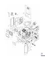
4.
TROUBLESHOOTING GUIDE
When your stove acts up, your first reaction may be to call for help.This guide may save time and money by
enabling you to solve simple problems yourself. Problems can be caused by generally five factors: 1) poor
fuel; 2) poor operation or maintenance; 3) poor installation; 4) component failure; 5) factory defect. You can
usually solve those problems related to 1 and 2. Your dealer can solve problems relating to 3, 4 and 5. Refer
to figures 32 - 34 to help locate indicated parts.
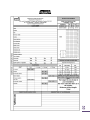
Should you need to contact your dealer or the manufacturer, please photocopy and fill out the form in
Appendix B. Try to answer as many questions as you can. Have it handy when you call. This will help you
obtain a much faster service.
Possible Causes:
Possible Remedies: (Unplug stove first when possible)
1.
Airflow pressure switch hose or pressure tap for hose
are blocked.
Unhook air hose from the airflow switch and blow through it. If air flows
freely, the hose and tube are fine. If air will not flow throw the hose, use a
thin wire to clear the blockage.
2.
The air inlet, burn pot, interior combustion air
chambers, combustion blower, or exhaust pipe are
blocked with ash or foreign material.
Follow all cleaning procedures in the maintenance section of the owner’s
manual.
3.
Vent pipe is incorrectly installed.
Check to make sure vent pipe installation meets the criteria in the owner’s
manual as well as the pipe manufacturer’s recommendations.
4.
The airflow pressure switch wire connections are
faulty.
Check the connectors attached to the pressure switch.
5.
The airflow pressure switch wires are pulled loose at
the connector on the wiring harness.
Check to see whether the wires are loose at the connectors.
6.
Exhaust blower failure.
This blower must turn on when you start the unit. If it does not, make sure
there is power on the connections. If the power is connected, the motor is
probably defective; if there is no power, see #7.
7.
Control board is not sending power to exhaust
blower.
If there is no power going to the blower, check all connections. If all wires
are properly connected, you have a defective control board.
8.
Control board not sending power to airflow pressure
switch.
There should be a 120-volt current going to the air switch after the stove has
been on. You will need a technician to perform this test.
9.
Airflow pressure switch has failed (very rare).
To test the airflow pressure switch, you need to disconnect the air hose from
the blower casing. With the other end still attached to the switch, very gently
suck on the loose end of the hose (you may want to completely disconnect
the hose from the stove and the switch first and make sure it is clear). If you
hear a click, the switch is working. BE CAREFUL: TOO MUCH SUCTION CAN
DAMAGE THE SWITCH.
Possible Causes:
Possible Remedies: (Unplug stove first when possible)
1.
The hopper is out of pellets.
Refill the hopper.
2.
The burn pot holes are blocked.
Remove the burn pot and clean it thoroughly.
3.
The air inlet, interior chambers, or exhaust system is
partly blocked.
Follow all cleaning procedures in the maintenance section of the owner’s
manual.
4.
One of the two augers motor has failed.
Remove the auger motor from the auger shaft and try to run the motor
separately by pressing the fuel feed button on the control board. Make sure
that the hopper lid is not open. If the motor turns, the shaft is jammed on
something. If the motor does not turn, the motor is defective or there is a
faulty connection with the control board. To remove the auger motor, take
the rear louver off the stove body. Loosen the two screws holding the motor
to the auger shaft.
5.
One of the two the auger shaft is jammed.
Remove the auger shaft from the auger housing. Start by emptying the
hopper. Take the rear louver off the stove body. Then take the auger motor
off by removing the screws that hold the motor to the auger shaft. Once the
motor is out, remove the four screws on the steel plate that holds the auger
shaft to the auger housing. Then rotate the bottom end of the auger shaft
down towards you until you can pull the shaft down out of the stove. After
you have removed the shaft, inspect it for bent flights, burrs, or broken
welds. Remove any foreign material that may have caused the jam. Also,
check the auger housing for signs of damage such as burrs, rough spots, or
grooves cut into the metal that could have caused a jam. Clean the auger
housing thoroughly to remove all pellet dust.
6.
The thermistor heat sensor has malfunctioned.
The thermistor is a heat sensor located on the exhaust housing. Its function is
to tell the control board that the unit has ignited properly by measuring the
heat in the exhaust. The pellet stove will not start feeding pellets at the
desired heat setting until it has received a signal from the thermistor heat
sensor. If the thermistor heat sensor is bad, the unit will stop after the
ignition cycle. If this situation occurs, call your dealer or technician.
Possible Causes:
Possible Remedies:
1.
Blockage in igniter tube or inlet for igniter tube.
Remove the burn pot and clean it thoroughly. Make sure that all openings
are clear. Find the place where the igniter tube comes out of the burn pot
housing. It is a small tube located on the back of the burn pot housing.
Make sure it is clear. Make sure there is no debris around the igniter element
or inside the igniter tube.
2.
Defective igniter element.
Supply power directly to the igniter element. Watch the tip of the igniter from
the front of the stove. After about 30 seconds, the tip should glow. If it does
not, the element is defective and must be replaced. You may need a
technician to perform this test.
3.
The thermistor heat sensor has malfunctioned.
The thermistor is a heat sensor located on the exhaust housing. Its function is
to tell the control board that the unit has ignited properly by measuring the
heat in the exhaust. The pellet stove will not start feeding pellets at the
desired heat setting until it has received a signal from the thermistor heat
sensor. If the thermistor heat sensor is bad, the unit will stop after the
ignition cycle. If this situation occurs, call your dealer or technician.
4.
The control board is not sending power to the
igniter.
Check the voltage going to the igniter during ignition. It should be a full
current. If the voltage is lower than full current, check the wiring. If the wiring
is functional and properly connected, the board is defective. You will need a
technician to perform this test.
5.
The pump is not connected properly or isn’t working
properly
Verify that the plug is connected properly and if the pump is running during
the lightning cycle. If the pump isn’t working make sure all connections are
good.
Possible Causes:
Possible Remedies:
1.
The igniter or the pump is defective or the wiring harness shorted.
The igniter fuse on the control board has blown.
Remove the control board cover and check if the F1 fuse appears to have
blown. Replace it with a 5 Amp 250V fuse. Plug the stove back on and try
to start the unit.
Possible Causes:
1.
The auger jammed, the auger motor is
defective or the wiring harness shorted.
2.
The auger fuse has blown.
Possible Remedies:
Remove the control board cover and check if the F2 fuse appears to have
blown. Replace it with a 3 Amp 250V fuse. Plug the stove back and try to
run the unit.
Start by emptying the hopper. Then, remove the auger motor by removing
the screws holding the motor to the auger shaft once the motor is out,
remove the four screws on the steel plate holding the auger shaft to the
auger housing. Then, rotate the bottom end of the auger shaft down
towards you until you can pull the shaft down out of the stove. After you
have removed the shaft, inspect it for bent flights, burrs, or broken welds.
Remove any foreign material that might have caused the jam. Also, check
the auger housing for signs of damage such as burrs, rough spots, or grooves
cut into the metal that could have caused a jam. Clean the auger housing
thoroughly to remove all pellet dust. Repeat the process with the burn pot
auger motor.
Possible Causes:
Possible Remedies:
1.
An overheat zone was detected on the auger
housing
The L-250 automatic high temperature switch is located on the top of the
auger housing. It sends a signal to the control board if the auger housing
overheats. Wait until the stove cools down AND THEN INSPECT YOUR UNIT.
Improper installation, poor maintenance, or a defective or missing
component may be causing the stove to overheat. Reset the stove and
restart it. Call a technician if you get this code again.
*** After 3 attempts, reset is no longer possible, call SBI technical support.
Possible Causes:
1.
The hopper lid has stayed open for more than 3
minutes
Possible Remedies:
As a security measure, the auger stops turning and feeding pellets as soon
as the hopper lid opens. It will resume normal operation as soon as the
hopper lid is closed. If the hopper lid stays open for more than 3 minutes,
the unit will stop and a code “d” will appear on the control board. Close the
hopper lid. Reset the unit and start it again.
If the lid is properly close the hopper lid switch is defective or misconnected
SMOKE SMELL COMING BACK INTO THE HOME
Possible Causes:
Possible Remedies:
1.
Inspect all vent pipe connections. This is a pressurized exhaust system. All
vent connector joints must be sealed and fastened in accordance with the
pellet pipe manufacturer's instructions to ensure consistent performance and
avoid smoke and ash spillage.
There is a leak in the vent pipe system.
2. A gasket on the exhaust blower housing or on the
clean out trap is in bad condition.
Inspect the gasket on the exhaust blower housing to make sure it is in good
condition. Make sure that all clean out trap gaskets are in good condition
and all bolts are tight.
AUGER MOTOR STOP FEEDING PELLETS AND COMES BACK ON
Possible Causes:
Possible Remedies:
1.
Start by emptying the hopper. Then, remove the auger motor by removing
the screws holding the motor to the auger shaft. Once the motor is out,
remove the four screws on the steel plate holding the auger shaft to the
auger housing. Then, rotate the bottom end of the auger shaft down
towards you until you can pull the shaft down out of the stove. After you
have removed the shaft, inspect it for bent flights, burrs, or broken welds.
Remove any foreign material that might have caused the jam. Also, check
the auger housing for signs of damage such as burrs, rough spots, or grooves
cut into the metal that could have caused a jam. Clean the auger housing
thoroughly to remove all pellet dust. Repeat the process whit the burn pot
auger motor.
The auger motor is overheating and tripping the
internal temperature shutoff (thermal protector).
•
•
•
GLASS “SOOTS” UP AT A VERY FAST RATE
FLAME IS LAZY, DARK, AND HAS BLACK TIPS
AFTER STOVE HAS BEEN ON FOR A WHILE, THE BURNPOT OVERFILLS
Possible Causes:
Possible Remedies:
1.
Stove or vent pipe is dirty, which restricts airflow
through the burn pot.
Follow all cleaning procedure in the maintenance section of the owner’s
manual.
2.
Vent pipe installed improperly.
Check to make sure the vent pipe has been installed according to the criteria
in the owner’s manual.
3.
Burn pot holes are blocked.
Remove the burn pot and clean it thoroughly.
4.
Blockage in air intake pipe.
Visually inspect the air intake pipe that leads into the burn pot for foreign
material.
5.
Combustion blower is not working properly.
Check if the blower is still working (separately – bypassing the control
board). Make sure that there is not any obstruction in the fresh air kit and
into the air intake tube.
6.
Bad pellets
(Applies to “GLASS SOOTS UP AT A VERY FAST RATE”
Only)
The brand of pellets or the batch of pellets that are being used may be of
poor quality. If possible, try a different brand of pellets. You might also
want to try a brand that is made from a different type of wood (softwood
vs. hardwood). Different woods have different characteristics when being
burned. Your pellets may also be too humid. Make sure you store your fuel
properly, in a dry ventilated area.
THE CONTROL BOARD DOES NOT DISPLAY ANY INFORMATION.
Possible Causes:
Possible Remedies :
1. A fuse on the control board has blown.
Remove the control board. Check if the F7 fuse on the back of it appears to
be bad. Replace it with a 7.5 Amp 250 Volt fuse. Plug the stove back in
and try to run the unit.
Possibles Causes:
Possibles Solutions:
Warning generated by a power failure while the stove
was running.
The stove will restart on the initial setting once it cools off.
Note: For a short power failure (less than 5 seconds), the stove will
continue to function at the selected speed.
SMOKE SMELL OR SOOT BUILD-UP
Because it is a pellet-burning device, your Euromax may emit a faint wood-burning odor. If this increases
beyond normal, or if you notice an unusual soot build-up on walls or furniture, check your exhaust system
carefully for leaks. All joints should be properly sealed. Also clean your stove, following instructions in
“MAINTENANCE”. If problem persists, contact your dealer.
5.
ELECTRICAL DIAGRAM
FIGURE 31
FIGURE 32
5.1
FIGURE 33
FUSE ACCESS:
All fuses are located inside the pc board box. You must remove the pc board cover to access the fuse. To do
so, simply remove the 5 screws securing it in place. Make sure you put the pc board box back in place before
you restart the unit.
FIGURE 34
49
6.
REPLACEMENT PARTS
Contact an Authorized ENERZONE Dealer to obtain any of these parts. Never use substitute materials. Use of
non-approved parts can result in poor performance and safety hazards.
#
1
1
2
3
4
5
6
7
8
9
10
11
12
13
14
15
16
17
18
19
20
21
22
23
24
25
26
27
28
29
30
31
32
33
34
35
36
37
38
39
40
41
42
43
44
45
46
ITEM
BLACK CAST IRON DOOR OVERLAY
BRUSHED NICKEL CAST IRON DOOR OVERLAY
BLACK ROUND WOODEN HANDLE
DOOR ASSEMBLY
SILICONE AND 1/2" x 8' BLACK GASKET REPLACEMENT KIT (DOOR)
DOOR HANDLE
DOOR LATCH KIT
SELF-ADHESIVE 1/8" X 3/8" GASKET HB26
EUROMAX REPLACEMENT GLASS
SPRING TENSION PIN 5/32" DIA X 1 1/2" LONG
BOTTOM GLASS RETAINER
TOP GLASS RETAINER
SCREW #8 - 32 X 5/16'' TRUSS QUADREX ZINC
BAFFLE
COMBUSTION POT ASSEMBLY
BURN POT SUPPORT ASSEMBLY
ROUND GASKET AND SILICONE KIT 5/16" X 6.6'
FIRE POT LATCH
ASH DRAWER ACCESS DOOR
BLACK 1/2'' ROUND X 9' GASKET KIT WITH ADHESIVE
PIN 5/16" x 1 1/2"
ZINC WASHER ID 13/32" X OD 13/16"
WING NUT 3/8"-16
ASH DRAWER ACCESS COVER
ASH DRAWER
BUILD TO ORDER
LEVELING BOLT 3/8-16 X 1 1/2"
500W - 120V IGNITER
SPRING CLIP
FRESH AIR INTAKE TUBE GASKET
DECORATIVE RIGHT SIDE ASSEMBLY
DECORATIVE COLUMN
HOPPER LID HANDLE
RIGHT SIDE DECORATIVE DOOR
UPPER SIDE DECORATIF PANEL
MAIN CONTROL BOARD WIRE HARNESS
THERMODISC 36T11 L250-25 AUTOMATIC
THERMODISC 36T12 F160
DOUBLE MAGNET
2 FOLD ALUMINUM LINER 3" X 14'' COMPRESSED TO 7"
3" TO 4" STAINLESS STEEL COLLAR
COMBUSTION BLOWER 120V-60Hz
HINGE 2'' X 1-1/2''
AIR PUMP ASSEMBLY (500 PCM, 115v, 60Hz, 1100 TPM)
3/8'' X 42" SILICONE HOSE
PRESSURE SWITCH
BLOWER WITH CAPACITOR (500 PCM, 115v, 60Hz, 1100 TPM)
PART #
AC01220
AC01222
30569
SE24179-01
AC06000
PL62296
AC09185
40018
PL62418
30101
PL62414
PL62413
30124
PL62412
SE62254
SE62302
AC06300
30686
SE62325
AC06900
30341
30205
30416
SE62318
SE62290
99999
30050
44133
30710
21345
SE62316
PL62317
30693
PL62322
PL62315
60326
44059
44058
30454
21077
49400
44104
30013
SE60047
49606
44029
SE44108
QTY
1
1
1
1
1
1
1
4.8583
1
1
1
1
10
1
1
1
1
1
1
1
2
1
1
1
1
1
4
1
24
1
1
2
3
1
2
1
1
1
8
1
2
1
6
1
2
1
1
50
#
47
48
49
50
51
52
53
54
55
56
57
58
59
60
61
62
63
64
65
66
67
68
69
70
71
72
73
74
75
76
77
78
79
80
81
82
83
84
85
ITEM
BLOWER ANTI-VIBRATION CUSHION
RIGHT BLOWER MOUNT
BLOWER (500 CFM, 115v, 60Hz, 1100 RPM)
CAPACITOR 10MF
CAPACITOR HOUSING
BLOWER WOOL RETAINER
WOOL SEAL FOR BLOWER
POWER CORD 96" X 18-3
THERMOSTAT TERMINAL
6 OUPUT MOTHER BOARD
REAR LOUVER
PRIMARY CHUTE GASKET
AUGER
GEAR MOTOR BRACKET
AUGER SUPPORT INSULATION
GEAR MOTOR FOR PELLET STOVE 3.5 RPM
AUGER BUSHING PLATE
BLOWER (500 CFM, 115v, 60Hz, 1100 RPM)
EXHAUST FAN ASSEMBLY
EXHAUST BLOWER GASKET
JUNCTION WIRE MAIN CONTROL BOARD TO LCD
EUROMAX TOUCH SCREEN ELECTRONIC BOARD (LCD)
LCD BRACKET
UPPER REAR PANEL
HOPPER LID SAFETY SWITCH
THERMISTOR
HOPPER LID ASSEMBLY
HOPPER STOPPER
ENERZONE TOP ASSEMBLY
TOP DECORATIVE GRILL
CAST IRON UPPER GRILLE EUROZONE 35 (DRILL & TAP)
FRONT DECORATIVE PANEL
DECORATIVE LEFT SIDE ASSEMBLY
LEFT SIDE DECORATIVE DOOR
MAINTENANCE GASKET KIT– PELLET HEATER
SCRAPER
EUROMAX INSTRUCTION MANUAL KIT
MILLIVOLT WHITE THERMOSTATS
HOT AIR PLENUM KIT – 4" x 10"
PART #
30335
PL62359
44108
60323
PL62420
PL62308
21350
60013
60036
44138
PL62314
21195
24030
24233
21193
44109
PL62281
44108
SE62293
21194
60327
44129
SE62421
PL62349
44098
44095
SE62348
PL62351
SE62324
SE62336
24177
SE62334
SE62331
PL62321
AC09190
PL62342
SE45432
44048
AC01330
QTY
4
2
1
1
1
1
1
1
1
1
1
1
2
1
2
1
1
1
1
1
1
1
1
1
1
1
1
1
1
1
1
1
1
1
1
1
1
1
1
51
52
APPENDIX A
Possible Vertical vent
length (feet)
HORIZONTAL AND VERTICAL VENT CHART
Possible Horizontal
vent length (feet)
For example, let’s imagine an installation consisting of a horizontal vent coming out at the back of the stove
on a total distance of 8 feet. This horizontal run is followed by a Tee and a 6-foot vertical rise. This type of
installation is not acceptable. As you can see, the vent termination is clearly outside the allowed
configuration zone on the chart because the venting system proposed does not have at least one foot of
vertical rise for each foot of horizontal run.
Instead, if the installation consisted of a horizontal vent coming out at the back of the stove on a total
distance of 4 feet, followed by a Tee and a 6-foot vertical rise, it would be acceptable. The installation end
should be within the allowable configuration zone on the chart since it would have at least one foot of
vertical rise for each foot of horizontal run. Furthermore, the total vertical rise would be at least 3-foot high.
WARNING: To reduce the risk of smoke spillage, never terminate with a horizontal run.
terminates with a horizontal run, add at least 3 feet of vertical rise.
If your system
53
APPENDIX B
INSPECTION FORM
54
APPENDIX C
LCD INTERFACE MOUNTING
Step 1
The LCD mounting bracket is located in the hopper of the appliance and is preassembled to be installed in a
right hand side configuration when facing the unit. If you are using the right hand side configuration go to the
following step. You also have the option of installing the LCD mounting bracket on the left hand side on the
back of the unit. To reverse the assembly to a left side configuration, extend the rail with the LCD support (E)
in order to access the two screws (A) which secures the rail mechanism to the mounting bracket. Remove the
screws, rotate the rail 180° and reassemble the rail to the mounting bracket using the screws previously
removed.
FIGURE 35
Step 2
Remove the screws (C) located on the top edge of the back of the appliance. Secure the mounting bracket
(B) in place with the same screws.
FIGURE 36
55
Step 3
Take the Telco black wire (D) which is located in the middle of the rear bottom panel and plug it into the
back of the LCD touch screen interface receptacle.
FIGURE 37
Step 4
Finally, secure the LCD touch screen housing (F) on the rail (E).
FIGURE 38
56
ENERZONE LIMITED LIFETIME WARRANTY
The warranty of the manufacturer extends only to the original consumer purchaser and is not transferable. This
warranty covers brand new products only, which have not been altered, modified nor repaired since shipment
from factory. Proof of purchase (dated bill of sale), model name and serial number must be supplied when
making any warranty claim to your ENERZONE dealer.
This warranty applies to normal residential use only. Damages caused by misuse, abuse, improper installation,
lack of maintenance, over firing, negligence or accident during transportation, power failures, downdrafts, or
venting problems are not covered by this warranty.
This warranty does not cover any scratch, corrosion, distortion, or discoloration. Any defect or damage caused
by the use of unauthorized parts or others than original parts void this warranty. An authorized qualified
technician must perform the installation in accordance with the instructions supplied with this product and all
local and national building codes. Any service call related to an improper installation is not covered by this
warranty.
The manufacturer may require that defective products be returned or that digital pictures be provided to
support the claim. Returned products are to be shipped prepaid to the manufacturer for investigation. If a
product is found to be defective, the manufacturer will repair or replace such defect. Transportation fees to ship
the product back to the purchaser will be paid by the manufacturer. Repair work covered by the warranty,
executed at the purchaser’s domicile by an authorized qualified technician requires the prior approval of the
manufacturer. Labour cost and repair work to the account of the manufacturer are based on predetermined
rate schedule and must not exceed the wholesale price of the replacement part. All parts and labour costs
covered by this warranty are limited according to the table below.
The manufacturer at its discretion may decide to repair or replace any part or unit after inspection and
investigation of the defect. The manufacturer may, at its discretion, fully discharge all obligations with respect to
this warranty by refunding the wholesale price of any warranted but defective parts. The manufacturer shall in
no event be responsible for any special, indirect, consequential damages of any nature, which are in excess of
the original purchase price of the product. A one-time replacement limit applies to all parts benefiting from a
lifetime coverage. This warranty applies to products purchased after October 1st, 2011.
WARRANTY APPLICATION
PARTS
LABOUR
DESCRIPTION
Combustion chamber (welds only), castings, heat exchanger (welds
only), auger, and ceramic glass (thermal breakage only*).
Plating* (defective manufacture) – subject to limitations above.
Stainless steel firebox components, surrounds and heat shields, ash
drawer, pedestal, and trims (aluminum extrusions).
Carbon steel firebox components, burn pot, glass retainers, and
handle assembly.
Blowers, igniter, PC board, auger motor, heat sensors, switches,
wiring, rheostat, and other controls.
Paint (peeling), gaskets, insulation, ceramic logs, masonry-like
panels, and ceramic fibre blankets.
Lifetime
4 years
Lifetime
n/a
5 years
3 years
3 years
2 years
2 years
1 year
1 year
n/a
*Pictures required
Shall your unit or a components be defective, contact immediately your ENERZONE dealer. Prior to your call
make sure you have the following information necessary to your warranty claim treatment:
•
•
Your name, address and telephone
number;
Bill of sale and dealer’s name;
•
•
Serial number and model name as indicated on
the nameplate fixed to the back of your unit;
Nature of the defect and any relevant information.
Before shipping your unit or defective component to our plant, you must obtain from your ENERZONE dealer
an Authorization Number. Any merchandise shipped to our plant without authorization will be refused
automatically and returned to sender.