1
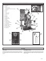
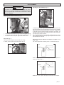
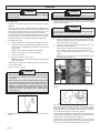
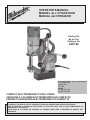
OPERATOR'S MANUAL MANUEL de L'UTILISATEUR MANUAL del OPERADOR Catalog No. No de Cat. Catálogo No. 4270-20 ALPHA INDUSTRIAL TOOL & EQUIPMENT 51 Tamarack Drive Thornhill, Ont L3T 4 W2 Canada PH. 905-731-1310 FAX 905-731-1044 COMPACT ELECTROMAGNETIC DRILL PRESS PERCEUSE À COLONNE ÉLECTROMAGNÉTIQUE COMPACTE PRENSA TALADRADORA ELECTROMAGNETICA COMPACTA TO REDUCE THE RISK OF INJURY, USER MUST READ AND UNDERSTAND OPERATOR'S MANUAL. AFIN DE RÉDUIRE LE RISQUE DE BLESSURES, L'UTILISATEUR DOIT LIRE ET BIEN COMPRENDRE LE MANUEL DE L'UTILISATEUR. PARA REDUCIR EL RIESGO DE LESIONES, EL USUARIO DEBE LEER Y ENTENDER EL MANUAL DEL OPERADOR. GENERAL SAFETY RULES FOR ALL POWER TOOLS WARNING! READ ALL INSTRUCTIONS Failure to follow all instructions listed below may result in electric shock, fire and/or serious injury. The term "power tool" in all of the warnings listed below refers to your mains-operated (corded) power tool or battery-opearted (cordless) power tool. SAVE THESE INSTRUCTIONS WORK AREA SAFETY 1. Keep work area clean and well lit. Cluttered or dark areas invite accidents. 2. Do not operate power tools in explosive atmospheres, such as in the presence of flammable liquids, gases, or dust. Power tools create sparks which may ignite the dust or fumes. 3. Keep children and bystanders away while operating a power tool. Distractions can cause you to lose control. ELECTRICAL SAFETY 4. Power tool plugs must match the outlet. Never modify the plug in any way. Do not use any adapter plugs with earthed (grounded) power tools. Unmodified plugs and matching outlets will reduce risk of electric shock. 5. Avoid body contact with earthed or grounded surfaces such as pipes, radiators, ranges and refrigerators. There is an increased risk of electric shock if your body is earthed or grounded. 6. Do not expose power tools to rain or wet conditions. Water entering a power tool will increase the risk of electric shock. 7. Do not abuse the cord. Never use the cord for carrying, pulling, or unplugging the power tool. Keep cord away from heat, oil, sharp edges, or moving parts. Damaged or entangled cords increase the risk of electric shock. 8. When operating a power tool outdoors, use an extension cord suitable for outdoor use. Use of a cord suitable for outdoor use reduces the risk of electric shock. PERSONAL SAFETY 9. Stay alert, watch what you are doing and use common sense when operating a power tool. Do not use a power tool while you are tired or under the influence of drugs, alcohol or medication. A moment of inattention while operating power tools may result in serious personal injury. 10. Use safety equipment. Always wear eye protection. Safety equipment such as dust mask, non-skid safety shoes, hard hat, or hearing protection used for appropriate conditions will reduce personal injuries. 11. Avoid accidental starting. Ensure the switch is in the offposition before plugging in. Carrying tools with your finger on the switch or plugging in power tools that have the switch on invites accidents. POWER TOOL USE AND CARE 16. Do not force the power tool. Use the correct power tool for your application. The correct power tool will do the job better and safer at the rate for which it was designed. 17. Do not use the power tool if the switch does not turn it on and off. Any power tool that cannot be controlled with the switch is dangerous and must be repaired. 18. Disconnect the plug from the power source and/or the battery pack from the power tool before making any adjustments, changing accessories, or storing power tools. Such preventive safety measures reduce the risk of starting the tool accidentally. 19. Store idle power tools out of the reach of children and do not allow persons unfamiliar with the power tools or these instructions to operate power tools. Power tools are dangerous in the hands of untrained users. 20. Maintain power tools. Check for misalignment or binding of moving parts, breakage of parts and any other condition that may affect the power tool's operation. If damaged, have the power tool repaired before use. Many accidents are caused by poorly maintained power tools. 21. Keep cutting tools sharp and clean. Properly maintained cutting tools with sharp cutting edges are less likely to bind and are easier to control. 22. Use the power tool, accessories and tool bits etc., in accordance with these instructions and in the manner intended for the particular type of power tool, taking into account the working conditions and the work to be performed. Use of the power tool for operations different from those intended could result in a hazardous situation. SERVICE 23. Have your power tool serviced by a qualified repair person using only identical replacement parts. This will ensure that the safety of the power tool is maintained. ALPHA INDUSTRIAL TOOL & EQUIPMENT 51 Tamarack Drive Thornhill, Ont L3T 4 W2 Canada PH. 905-731-1310 FAX 905-731-1044 12. Remove any adjusting key or wrench before turning the power tool on. A wrench or a key left attached to a rotating part of the power tool may result in personal injury. 13. Do not overreach. Keep proper footing and balance at all times. This enables better control of the power tool in unexpected situations. 14. Dress properly. Do not wear loose clothing or jewellery. Keep your hair, clothing and gloves away from moving parts. Loose clothes, jewellery, or long hair can be caught in moving parts. 15. If devices are provided for the connection of dust extraction and collection facilities, ensure these are connected and properly used. Use of these devices can reduce dust-related hazards. page 3 SPECIFIC SAFETY RULES FOR ELECTROMAGNETIC DRILL PRESS 1. Always use safety strap when drilling overhead or on a vertical surface (see Safety Strap under Operation). Mounting can release. 2. Clean the surface before attaching the drill stand to the work surface. Paint, rust, scale, or uneven surfaces decrease the holding strength of the magnet. Chips, burrs, dirt and other foreign matter on the surface of the magnet base will also decrease holding power. 3. Do not attach magnetic base to nonmagnetic grades of stainless steel. The magnetic base WILL NOT hold. The electromagnetic drill press attaches magnetically to 3/8" or thicker ferrous stock. Do not use on stock less than 3/8". 4. Wet connections are shock hazards. If the plug or connections get wet, turn power off to the outlet before unplugging the tool. Prevent cutting fluid from traveling along the cord and contacting the outlet, extension cord connections or tool plug. Each time tool is plugged in, elevate extension cord or gang box connections and arrange a drip loop. 5. Maintain labels and nameplates. These carry important information. If unreadable or missing, contact a MILWAUKEE service facility for a free replacement. 6. Wear ear protectors with impact drills. Exposure to noise can cause hearing loss. 7. Hold power tools by insulated gripping surfaces when performing an operation where the cutting tool may contact hidden wiring or its own cord. Contact with a live wire will make exposed metal parts of the tool live and shock the operator. 8. WARNING! Some dust created by power sanding, sawing, grinding, drilling, and other construction activities contains chemicals known to cause cancer, birth defects or other reproductive harm. Some examples of these chemicals are: lead from lead-based paint crystalline silica from bricks and cement and other masonry products, and arsenic and chromium from chemically-treated lumber. Your risk from these exposures varies, depending on how often you do this type of work. To reduce your exposure to these chemicals: work in a well ventilated area, and work with approved safety equipment, such as those dust masks that are specially designed to filter out microscopic particles. 9. Safety Strap A. Do not use near acids or bleaching agents. B. Do not use for overhead lifting. C. Do not use strap if webbing is cut. D. Webbing must be protected from sharp edges. E. All hardware must be in line with direction of pull for rated capacity. Symbology Volts Alternating Current Amps Double Insulated No Load Revolutions per Minute (RPM) Underwriters Laboratories, Inc. Canadian Standards Association DANGER! To reduce the risk of injury, always keep hands, rags, clothing, etc. away from moving parts and chips. Do not try to remove chips while the cutter is rotating. Chips are sharp and can pull objects into moving parts. Specifications Cat. No. 4270-20 Volts AC Only Amps No Load RPM Arbor Bore *Twist Drill HSS Cutter 120 9.0 450 3/4" 1/2" 1-1/2" * Requires use of 1/2" drill chuck adapter, see "Accessories." page 4 FUNCTIONAL DESCRIPTION 1. Drill motor 2. Slide 3. Wrench storage 4 4. Stop knob 5. Pinion 6. Hub 7. Handle screw 8. Feed handle 9. Grip 2 1 (includes 3/32" and 3/16" hex keys) 3 6 5 7 10. Housing 8 11. Cord 12. Safety strap 9 13. Magnetic base 14. Spacer 17 15. Drill spindle 16. Support bracket 17. Cutting fluid reservoir 18. Control panel 10 16 11 19. Magnet indicator light 20. Magnet switch 12 21. Drill on/off switch 22. Hand pump 15 13 14 18 19 21 22 20 FEATURES Line Lockout Motor/Magnet Interlock The line lockout prevents the drill motor from starting when line power is first applied to the system or after a momentary power loss. To reset tool, turn magnet switch to "OFF" position and drill on/off switch to "OFF" position. The motor/magnet interlock is a feature that prevents power from being applied to the drill motor if the magnet is not energized. The motor magnet interlock also prevents the magnet from being de-energized while the motor is running. page 5 GROUNDING EXTENSION CORDS WARNING! Improperly connecting the grounding wire can result in the risk of electric shock. Check with a qualified electrician if you are in doubt as to whether the outlet is properly grounded. Do not modify the plug provided with the tool. Never remove the grounding prong from the plug. Do not use the tool if the cord or plug is damaged. If damaged, have it repaired by a MILWAUKEE service facility before use. If the plug will not fit the outlet, have a proper outlet installed by a qualified electrician. Grounded Tools: Tools with Three Prong Plugs Tools marked Grounding Required have a three wire cord and three prong grounding plug. The plug must be connected to a properly grounded outlet (See Figure A). If the tool should electrically malfunction or break down, grounding provides a low resistance path to carry electricity away from the user, reducing the risk of electric shock. Fig. A Your tool must be plugged into an appropriate outlet, properly installed and grounded in accordance with all codes and ordinances. The plug and outlet should look like those in Figure A. Double Insulated Tools: Tools with Two Prong Plugs page 6 The smaller the gauge number of the wire, the greater the capacity of the cord. For example, a 14 gauge cord can carry a higher current than a 16 gauge cord. When using more than one extension cord to make up the total length, be sure each cord contains at least the minimum wire size required. If you are using one extension cord for more than one tool, add the nameplate amperes and use the sum to determine the required minimum wire size. Guidelines for Using Extension Cords The grounding prong in the plug is connected through the green wire inside the cord to the grounding system in the tool. The green wire in the cord must be the only wire connected to the tool's grounding system and must never be attached to an electrically live terminal. Tools marked Double Insulated do not require grounding. They have a special double insulation system which satisfies OSHA requirements and complies with the applicable standards of Underwriters Laboratories, Inc., the Canadian Standard Association and the National Electrical Code. Double Insulated tools may be used in either of the 120 volt outlets shown in Figures B and C. Grounded tools require a three wire extension cord. Double insulated tools can use either a two or three wire extension cord. As the distance from the supply outlet increases, you must use a heavier gauge extension cord. Using extension cords with inadequately sized wire causes a serious drop in voltage, resulting in loss of power and possible tool damage. Refer to the table shown to determine the required minimum wire size. If you are using an extension cord outdoors, be sure it is marked with the suffix W-A (W in Canada) to indicate that it is acceptable for outdoor use. Be sure your extension cord is properly wired and in good electrical condition. Always replace a damaged extension cord or have it repaired by a qualified person before using it. Protect your extension cords from sharp objects, excessive heat and damp or wet areas. Recommended Minimum Wire Gauge for Extension Cords* Nameplate Amperes 0-5 5.1 - 8 8.1 - 12 12.1 - 15 15.1 - 20 Extension Cord Length 25' 50' 75' 100' 150' 200' 16 16 14 12 10 16 14 12 10 10 16 16 14 12 10 14 12 10 10 -- 12 10 ---- 12 ----- * Based on limiting the line voltage drop to five volts at 150% of the rated amperes. READ AND SAVE ALL INSTRUCTIONS FOR FUTURE USE. Fig. B Fig. C TOOL ASSEMBLY WARNING! To reduce the risk of injury, always unplug tool before attaching or removing accessories or making adjustments. Use only specifically recommended accessories. Others may be hazardous. Adjusting the Gib Assembly (Fig. 3) Fig. 3 Attaching Feed Handles and Grips (Fig. 1) Fig. 1 1. Assemble the feed handles and grips to the hub. Tighten securely. 2. To mount the hub to either side, align the two (2) dowel pins on the hub with the holes in the pinion. Tighten the handle screw. Stop Knob (Fig. 2) The stop knob is designed to stop the slide from moving. To install, screw stop knob into location shown (Fig. 2). Fig. 2 Stop knob To adjust the gib, loosen or tighten the gib adjustment set screws on the side of the support housing accordingly with the 3/32" hex key provided. Tightening the set screws increases friction on the slide. The gib should be set tight enough to support the weight of the drill in any position. All adjusting screws should be set to provide smooth and even travel over the entire length of slide movement. The set screws contain a nylon patch that prevents them from moving freely. Additional adjustment of the gib may be required from time to time with extended use of the tool. Adjusting the Support Bracket and Spacer for Depth of Cut (Figs. 4 & 5) This unit is shipped from the factory set for 1" depth cutters (Fig. 4). Fig. 4 Spacer Support bracket When using 2" depth cutters, install support bracket with spacer on bottom, as shown in Fig. 5. Fig. 5 Spacer Support bracket NOTE: Do not use a spacer and support bracket with chuck adapter. page 7 OPERATION WARNING! WARNING! To reduce the risk of injury, wear safety goggles or glasses with side shields. To reduce the risk of injury, do not hold workpiece by hand. 5. Typical Operation 1. Check the work surface to make sure it is clean and free of foreign materials. WARNING! Paint, rust, scale or uneven surfaces decrease the holding strength of the magnet. Chips, burrs, dirt and other foreign materials on the surface of the magnetic base will also decrease holding power. Use a smooth, flat file to keep the magnet clean and free of nicks. The electromagnetic drill press attaches magnetically to 3/8" or thicker ferrous stock. Do not use on stock less than 3/8". The magnetic base WILL NOT hold on nonmagnetic grades of stainless steel. 2. To reduce the risk of injury, always use a safety strap when drilling overhead or on a vertical surface. 6. To install/remove cutter: A. Raise the drill motor to its highest position. Tighten stop knob. B. Insert cutter into drill spindle with the two (2) flats of the cutter aligned with set screws. Make sure the center pin is inserted into the cutter. NOTE: Cutter should be fully seated into drill spindle. C. Tighten set screws with 3/16" hex key provided. D. Loosen the stop knob. E. Reverse procedure to remove cutter. Position the tool so the center pin is directly over the desired cutting location. Push the magnet switch to the ON position. The magnet indicator light will turn on. Use a safety strap on vertical or overhead situations (Fig. 7). A. Route the safety strap, ring side first, through the lower slot, and wrap it tightly around a solid, rigid structure as shown. Make sure the strap is not twisted. B. Hook the safety strap snaphook provided to the ring. Eliminate any slack in the strap. C. When using on a vertical surface, secure the safety strap with a c-clamp or similar device. This will hold the strap in place and prevent the tool from sliding down the vertical surface. NOTE: Do not clamp to the strap. This may damage the strap and cause it to break (Fig. 7). NOTE: Do not remove cutter unless slug is removed. Slug may eject unexpectedly. Fig. 7 Avoid contact with cutter tips. Periodically inspect the cutter tips for loose or damaged tips. 3. Plug in tool to power source. C-clamp WARNING! Do not use cutting fluid in an overhead or any other position that allows cutting fluid to enter motor or switch enclosure. Wet connections are shock hazards. Prevent cutting fluid from traveling along cord and contacting the outlet, extension cord connections or tool plug. Each time tool is plugged in, elevate extension cord or gang box connections and arrange a drip loop (See Fig. 6). If plug or connections get wet, turn power off to outlet before unplugging tool. 7. With the drill on/off switch in the "OFF" position, fill the cutting fluid reservoir with cutting fluid through the slots in the drill spindle (Fig. 8). Fig. 8 Fig. 6 The cutting fluid reservoir will empty as the center pin contacts the work surface. When notching or slotting, it is required to spray cutting fluid directly to the cutter and work piece with the supplied hand pump. Keep hand pump away from moving parts. Failure to use the lubricant properly will cause cutter damage. 4. Move the spindle up so the cutter and center pin are above the work surface. The use of HAWG WASH® cutting fluid is recommended for long life of these cutters. The operator is responsible for the application of lubricants other than HAWG WASH® cutting fluid. In overhead or vertical cutting applications, do not use cutting fluids. Use only lubricant pastes or sprays recommended for high speed cutting. Do not allow lubricant pastes and sprays to enter tool. page 8 8. Start the drill motor by pulling the drill on/off switch to the "ON" position. WARNING! To reduce the risk of injury, always keep hands, rags, clothing, etc. away from moving parts and chips. Do not try to remove chips while the cutter is rotating. Chips are sharp and can pull objects into moving parts (see Fig. 9). Fig. 9 WARNING! Excessive force will break magnet free. 10. Keep constant pressure throughout the entire operation to prevent chips and burrs from falling under the cutting edges. Cutting debris under the cutter can make cutting difficult or impossible. 11. When the cut is complete, withdraw the cutter while the drill spindle is still rotating. 12. Stop the drill motor by pushing in the drill on/off switch to the "OFF" position. 13. When the drill spindle has stopped rotating, use a pliers to remove cutting debris and chips from the cutter and spindle. Use care to avoid damaging the cutter teeth. 14. If the slug is still present in the cutter, rotate the feed handle to highest position. This will eject the slug from the cutter. 9. These units have a 8:1 feed ratio: i.e. for every pound applied to the handle, you create eight pounds on the drill point. Even large bits only require a small amount of pressure on the handle. Example: 20 Pounds on the handle creates 160 Pounds on the drill point. When feeding the cutter into the material, apply only enough force to produce a curled chip. Applying too little force will result in small broken chips and increased cutting time. Applying too much force will cause overheating of the cutter resulting in short cutter life. Overheating of the cutter can be noticed when cutter and chips turn brown or blue. Excessive force can cause the cutter to slow down to a point where cutting time will increase. The use of cutting lubricants will reduce cutting heat and increase cutter life The center pin is spring loaded. Provide protection from ejected slug for people and property below cutting area. 15. Make sure you have a firm grip on the tool before turning off the magnet. Push the magnet switch to the "OFF" position. The magnet indicator light will turn off. Use less feed pressure when slotting or notching because there is less support for the cutting edges in these situations. page 9 MAINTENANCE ACCESSORIES WARNING! To reduce the risk of injury, always unplug your tool before performing any maintenance. Never disassemble the tool or try to do any rewiring on the tool's electrical system. Contact a MILWAUKEE service facility for ALL repairs. Maintaining Tools Keep your tool in good repair by adopting a regular maintenance program. Before use, examine the general condition of your tool. Inspect guards, switches, tool cord set and extension cord for damage. Check for loose screws, misalignment, binding of moving parts, improper mounting, broken parts and any other condition that may affect its safe operation. If abnormal noise or vibration occurs, turn the tool off immediately and have the problem corrected before further use. Do not use a damaged tool. Tag damaged tools DO NOT USE until repaired (see Repairs). Under normal conditions, relubrication is not necessary until the motor brushes need to be replaced. After six months to one year, depending on use, return your tool to the nearest MILWAUKEE service facility for the following: Lubrication Brush inspection and replacement Mechanical inspection and cleaning (gears, spindles, bearings, housing, etc.) Electrical inspection (switch, cord, armature, etc.) Testing to assure proper mechanical and electrical operation WARNING! To reduce the risk of injury, always unplug the tool before attaching or removing accessories. Use only specifically recommended accessories. Others may be hazardous. For a complete listing of accessories refer to your MILWAUKEE Electric Tool catalog or go on-line to www.milwaukeetool.com. To obtain a catalog, contact your local distributor or a service center. Safety Strap 4ft. Cat. No. 48-58-0090 HAWG WASH® Cutting Fluid Case of twelve-16oz. bottles, which makes one gallon of lubricant per bottle. Cat No. 49-32-0081 HAWG WASH® Hand Pump Cat. No. 44-46-0090 1/2" Drill Chuck Adapter Also includes chuck and chuck key. Cat. No. 48-66-2125 WARNING! To reduce the risk of injury, electric shock and damage to the tool, never immerse your tool in liquid or allow a liquid to flow inside the tool. Cleaning Clean dust and debris from vents. Keep the tool handles clean, dry and free of oil or grease. Use only mild soap and a damp cloth to clean your tool since certain cleaning agents and solvents are harmful to plastics and other insulated parts. Some of these include: gasoline, turpentine, lacquer thinner, paint thinner, chlorinated cleaning solvents, ammonia and household detergents containing ammonia. Never use flammable or combustible solvents around tools. Repairs If your tool is damaged, return the entire tool to the nearest service center. page 10 FIVE YEAR TOOL LIMITED WARRANTY Every MILWAUKEE tool is tested before leaving the factory and is warranted to be free from defects in material and workmanship. MILWAUKEE will repair or replace (at MILWAUKEEs discretion), without charge, any tool (including battery chargers) which examination proves to be defective in material or workmanship from five (5) years after the date of purchase. Return the tool and a copy of the purchase receipt or other proof of purchase to a MILWAUKEE Factory Service/Sales Support Branch location or MILWAUKEE Authorized Service Station, freight prepaid and insured. This warranty does not cover damage from repairs made or attempted by other than MILWAUKEE authorized personnel, abuse, normal wear and tear, lack of maintenance, or accidents. Battery Packs, Flashlights, and Radios are warranted for one (1) year from the date of purchase. THE REPAIR AND REPLACEMENT REMEDIES DESCRIBED HEREIN ARE EXCLUSIVE. IN NO EVENT SHALL MILWAUKEE BE LIABLE FOR ANY INCIDENTAL, SPECIAL, OR CONSEQUENTIAL DAMAGES, INCLUDING LOSS OF PROFITS. THIS WARRANTY IS EXCLUSIVE AND IN LIEU OF ALL OTHER WARRANTIES, OR CONDITIONS, WRITTEN OR ORAL, EXPRESSED OR IMPLIED FOR MERCHANTABLILITY OR FITNESS FOR PARTICULAR USE OR PURPOSE. This warranty gives you specific legal rights. You may also have other rights that vary from state to state and province to province. In those states that do not allow the exclusion of implied warranties or limitation of incidental or consequential damages, the above limitations or exclusions may not apply to you. This warranty applies to the United States, Canada, and Mexico only.