1
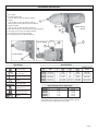
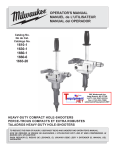
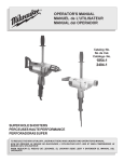
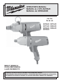
OPERATOR'S MANUAL
MANUEL de L'UTILISATEUR
MANUAL del OPERADOR
Cat. No.
No de cat.
9070-20 9075-20
9071-20 9092-20
9072-20 9096-20
9072-22
IMPACT WRENCH
CLÉ À PERCUSSION
LLAVE DE IMPACTO
TO REDUCE THE RISK OF INJURY, USER MUST READ OPERATOR'S MANUAL.
AFIN DE RÉDUIRE LE RISQUE DE BLESSURES, L'UTILISATEUR DOIT LIRE LE MANUEL DE L'UTILISATEUR.
PARA REDUCIR EL RIESGO DE LESIONES, EL USUARIO DEBE LEER EL MANUAL DEL OPERADOR.
GENERAL SAFETY RULES — FOR ALL POWER TOOLS
WARNING
READ ALL INSTRUCTIONS
Failure to follow all instructions listed below may result in electric shock, fire and/or serious injury. The term "power tool" in all of the
warnings listed below refers to your mains-operated (corded) power tool or battery-opearted (cordless) power tool.
SAVE THESE INSTRUCTIONS
POWER TOOL USE AND CARE
WORK AREA SAFETY
1.
Keep work area clean and well lit. Cluttered or dark areas invite accidents.
2.
Do not operate power tools in explosive atmospheres, such as
in the presence of flammable liquids, gases, or dust. Power tools
create sparks which may ignite the dust or fumes.
3.
Keep children and bystanders away while operating a power tool.
Distractions can cause you to lose control.
ELECTRICAL SAFETY
4.
Power tool plugs must match the outlet. Never modify the plug in
any way. Do not use any adapter plugs with earthed (grounded)
power tools. Unmodified plugs and matching outlets will reduce risk
of electric shock.
5.
Avoid body contact with earthed or grounded surfaces such as
pipes, radiators, ranges and refrigerators. There is an increased risk
of electric shock if your body is earthed or grounded.
6.
Do not expose power tools to rain or wet conditions. Water entering
a power tool will increase the risk of electric shock.
7.
Do not abuse the cord. Never use the cord for carrying, pulling, or
unplugging the power tool. Keep cord away from heat, oil, sharp
edges, or moving parts. Damaged or entangled cords increase the
risk of electric shock.
8.
When operating a power tool outdoors, use an extension cord suitable for outdoor use. Use of a cord suitable for outdoor use reduces
the risk of electric shock.
16. Do not force the power tool. Use the correct power tool for your
application. The correct power tool will do the job better and safer at
the rate for which it was designed.
17. Do not use the power tool if the switch does not turn it on and off.
Any power tool that cannot be controlled with the switch is dangerous
and must be repaired.
18. Disconnect the plug from the power source and/or the battery pack
from the power tool before making any adjustments, changing accessories, or storing power tools. Such preventive safety measures
reduce the risk of starting the tool accidentally.
19. Store idle power tools out of the reach of children and do not allow persons unfamiliar with the power tools or these instructions
to operate power tools. Power tools are dangerous in the hands of
untrained users.
20. Maintain power tools. Check for misalignment or binding of moving
parts, breakage of parts and any other condition that may affect the
power tool's operation. If damaged, have the power tool repaired
before use. Many accidents are caused by poorly maintained power
tools.
21. Keep cutting tools sharp and clean. Properly maintained cutting
tools with sharp cutting edges are less likely to bind and are easier to
control.
22. Use the power tool, accessories and tool bits etc., in accordance
with these instructions and in the manner intended for the particular type of power tool, taking into account the working conditions
and the work to be performed. Use of the power tool for operations
different from those intended could result in a hazardous situation.
SERVICE
PERSONAL SAFETY
9.
Stay alert, watch what you are doing and use common sense when
operating a power tool. Do not use a power tool while you are tired
or under the influence of drugs, alcohol or medication. A moment
of inattention while operating power tools may result in serious personal
injury.
10. Use safety equipment. Always wear eye protection. Safety equipment such as dust mask, non-skid safety shoes, hard hat, or hearing
protection used for appropriate conditions will reduce personal injuries.
23. Have your power tool serviced by a qualified repair person using
only identical replacement parts. This will ensure that the safety of
the power tool is maintained.
SPECIFIC SAFETY RULES
1.
Hold power tools by insulated gripping surfaces when performing
an operation where the cutting tool may contact hidden wiring or
its own cord. Contact with a "live" wire will make exposed metal parts
of the tool "live" and shock the operator.
11. Avoid accidental starting. Ensure the switch is in the off-position
before plugging in. Carrying tools with your finger on the switch or
plugging in power tools that have the switch on invites accidents.
2.
Maintain labels and nameplates. These carry important information.
If unreadable or missing, contact a MILWAUKEE service facility for a
free replacement.
12. Remove any adjusting key or wrench before turning the power
tool on. A wrench or a key left attached to a rotating part of the power
tool may result in personal injury.
3.
WARNING! Some dust created by power sanding, sawing, grinding,
drilling, and other construction activities contains chemicals known to
cause cancer, birth defects or other reproductive harm. Some examples
of these chemicals are:
lead from lead-based paint
crystalline silica from bricks and cement and other masonry products,
and
arsenic and chromium from chemically-treated lumber.
Your risk from these exposures varies, depending on how often you do
this type of work. To reduce your exposure to these chemicals: work in
a well ventilated area, and work with approved safety equipment, such
as those dust masks that are specially designed to filter out microscopic
particles.
13. Do not overreach. Keep proper footing and balance at all times. This
enables better control of the power tool in unexpected situations.
14. Dress properly. Do not wear loose clothing or jewellery. Keep your
hair, clothing and gloves away from moving parts. Loose clothes,
jewellery, or long hair can be caught in moving parts.
15. If devices are provided for the connection of dust extraction and
collection facilities, ensure these are connected and properly used.
Use of these devices can reduce dust-related hazards.
page 2
•
•
•
FUNCTIONAL DESCRIPTION
1. Drive shank
2. Forward/reverse switch
(Cat. No. 9072-20, 9072-22, 9092-20, 9096-20)
3. Trigger
1
(Cat. No. 9072-20, 9072-22, 9092-20, 9096-20)
Rocker switch (Cat. No. 9070-20, 9071-20, 9075-20)
4. Speed control dial
(Cat. No. 9072-20, 9072-22, 9092-20, 9096-20)
5. Quik-Lok® cord (Cat. No. 9072-20, 9072-22, 9092-20, 9096-20)
6. Quick change chuck (Cat. No. 9092-20, 9096-20)
7. Tool hanger (Cat. No. 9092-20, 9096-20)
8. Tool hanger ring (Cat. No. 9092-20, 9096-20)
2
Cat. No. 9072-20
9072-22
3
4
5
8
Cat. No. 9092-20
7
6
Cat. No. 9075-20
3
Specifications
Symbology
Double Insulated
Volts Alternating Current/
Direct Current
Volts Alternating Current
Amperes
Impacts per Minute
Under Load (IPM)
Underwriters
Laboratories, Inc.
Canadian
Standards Association
Mexican Approvals
Marking
Cat.
No.
9070-20
9071-20
9072-20
9072-22
9075-20
9092-20
9096-20
Volts
120 AC/DC
120 AC/DC
120 AC Only
120 AC Only
120 AC/DC
120 AC Only
120 AC Only
A
7
7
7
7
7
7
7
No Load
RPM
1800
1800
600-1800
600-1800
1750
600-1800
600-1800
Drive
Impacts Per Average Torque
Output
Shank
Minute
1/2"
2600
300 ft-lbs.
1/2"
2600
300 ft-lbs.
1/2"
1000-2600
100-300 ft-lbs.
1/2"
1000-2600
100-300 ft-lbs.
3/4"
2500
380 ft-lbs.
7/16" Hex 1000-2600
100-315 ft-lbs.
5/8" Hex
1000-2600
100-315 ft-lbs.
Quick Change Chuck Capacities*
Cat. No.
9070-20
9072-20
9072-22
9092-20
9096-20
Quick Change Auger Bits
1-1/2"
1-1/2"
1-1/2"
1-1/2"
1-1/2"
Selfeed Bits
2-9/16"
2-9/16"
2-9/16"
2-9/16"
2-9/16"
* Only for use with the 7/16" or 5/8" Hex Quick Change chuck, standard equiptment on the 9092-20 (7/16") and 9096-20 (5/8"), optional
accessory (Cat. No. 48-66-0061) on other models.
page 3
GROUNDING
EXTENSION CORDS
WARNING
Improperly connecting the grounding wire can result in the risk of
electric shock. Check with a qualified electrician if you are in doubt
as to whether the outlet is properly grounded. Do not modify the
plug provided with the tool. Never remove the grounding prong
from the plug. Do not use the tool if the cord or plug is damaged. If
damaged, have it repaired by a MILWAUKEE service facility before
use. If the plug will not fit the outlet, have a proper outlet installed
by a qualified electrician.
Grounded Tools:
Tools with Three Prong Plugs
Tools marked “Grounding Required”
have a three wire cord and three
prong grounding plug. The plug must
be connected to a properly grounded
outlet (See Figure A). If the tool should
electrically malfunction or break down,
grounding provides a low resistance
path to carry electricity away from
the user, reducing the risk of electric
shock.
•
If you are using an extension cord outdoors, be sure it is marked with
the suffix “W-A” (“W” in Canada) to indicate that it is acceptable for
outdoor use.
•
Be sure your extension cord is properly wired and in good electrical
condition. Always replace a damaged extension cord or have it repaired
by a qualified person before using it.
•
Protect your extension cords from sharp objects, excessive heat and
damp or wet areas.
Fig. A
Your tool must be plugged into an appropriate outlet, properly installed and
grounded in accordance with all codes and ordinances. The plug and outlet
should look like those in Figure A.
Double Insulated Tools:
Tools with Two Prong Plugs
page 4
The smaller the gauge number of the wire, the greater the capacity of the
cord. For example, a 14 gauge cord can carry a higher current than a 16
gauge cord. When using more than one extension cord to make up the total
length, be sure each cord contains at least the minimum wire size required. If
you are using one extension cord for more than one tool, add the nameplate
amperes and use the sum to determine the required minimum wire size.
Guidelines for Using Extension Cords
The grounding prong in the plug is connected through the green wire inside
the cord to the grounding system in the tool. The green wire in the cord must
be the only wire connected to the tool's grounding system and must never
be attached to an electrically “live” terminal.
Tools marked “Double Insulated” do
not require grounding. They have a
special double insulation system which
satisfies OSHA requirements and
complies with the applicable standards
of Underwriters Laboratories, Inc., the
Canadian Standard Association and
the National Electrical Code. Double
Insulated tools may be used in either
of the 120 volt outlets shown in Figures
B and C.
Grounded tools require a three wire extension cord. Double insulated tools
can use either a two or three wire extension cord. As the distance from the
supply outlet increases, you must use a heavier gauge extension cord. Using extension cords with inadequately sized wire causes a serious drop in
voltage, resulting in loss of power and possible tool damage. Refer to the
table shown to determine the required minimum wire size.
Recommended Minimum Wire Gauge
for Extension Cords*
Nameplate
Amperes
0-5
5.1 - 8
8.1 - 12
12.1 - 15
15.1 - 20
Extension Cord Length
25' 50'
16
16
14
12
10
16
16
14
12
10
75' 100' 150' 200'
16
14
12
10
10
14
12
10
10
--
12
10
----
12
-----
* Based on limiting the line voltage drop to five
volts at 150% of the rated amperes.
READ AND SAVE ALL INSTRUCTIONS
FOR FUTURE USE.
Fig. B
Fig. C
TOOL ASSEMBLY
WARNING
Fig. 3
To reduce the risk of injury, always unplug tool before attaching
or removing accessories or making adjustments. Use only specifically recommended accessories. Others may be hazardous.
Removing and Replacing Quik-Lok® Cords (Fig. 1) Cat. No. 9072-20,
9072-22, 9092-20 and 9096-20
Drive shank
MILWAUKEE's exclusive Quik-Lok® Cords provide instant field replacement
or substitution.
Fig. 1
1.
To attach a socket or other accessory, push the accessory onto the
drive shank until it snaps into place.
2.
To remove the accessory, pull it off the drive shank.
Attaching and Removing Accessories (Fig. 4) Cat. No. 9070-20, 907220, 9072-22
1.
To remove the Quik-Lok® Cord, turn the cord nut 1/4 turn to the left and
pull it out.
2.
To replace the Quik-Lok® Cord, align the connector keyways and push
the connector in as far as it will go. Turn the cord nut 1/4 turn to the
right to lock.
These impact wrenches are intended only for use with sockets designed
for impact wrenches and that have a 1/2" square drive. Other sockets could
shatter or break, causing injury.
Fig. 4
Attaching and Removing the Tool Hanger (Fig. 2) Cat. No. 9092-20,
9096-20, or as an accessory
Fig. 2
Ring
Gear case
screws
Tool
hanger
Drive shank
1.
To attach, remove the two top gear case screws (Fig. 2).
2.
Place the ring through the tool hanger.
3.
Position the tool hanger on the tool over the two gear case screw
holes.
4.
Replace the two gear case screws. Hand tighten the screws.
5.
To remove, reverse the procedure.
Detent pin
1.
To attach a socket or other accessory, align the hole in the accessory
with the detent pin on the drive shank. Hold the detent pin in while
pushing the socket onto the drive shank. The detent pin will snap into
place in the hole to secure the socket.
2.
To remove the accessory, insert a nail or other thin object into the hole
in the accessory and press the detent pin in. Pull the accessory off the
drive shank.
Attaching and Removing Accessories (Fig. 5) Cat. No. 9092-20, 9096-20,
or other Impact Wrenches using the Quick Change 1/2" Square Drive
to 7/16" Hex Adapter
Cat. No. 9092-20 and accessory Cat. No. 48-66-0061 are intended for use
with drill bits and adapters with a 7/16" Hex Quick Change shank. Cat. No.
9096-20 is intended for use with drill bits and adapters with a 5/8" Hex Quick
Change shank. Both Hex Quick Change shanks have a ball-retainer groove.
They are not intended for use with Hex Shank Bit Extensions.
Fig. 5
WARNING
Open (Release)
Ball-retainer
groove
Use only sockets and other accessories specifically designed for
use on impact wrenches and drivers. Other sockets and accessories might shatter or break causing injury.
Attaching and Removing Accessories (Fig. 3) Cat. No. 9071-20, 9075-20
This impact wrench is intended only for use with sockets designed for impact
wrenches and that have a 1/2" square drive (3/4" square drive for Cat. No.
9075-20). Other sockets could shatter or break, causing injury.
Closed (Locked)
1.
To attach an accessory, pull the chuck collar forward and insert the accessory shank. Release the collar. It may be necessary to pull the bit
out slightly to engage the holding mechanism.
2.
To remove the accessory, pull the chuck collar forward and remove the
accessory. Release the collar.
page 5
OPERATION
WARNING
Starting, Stopping and Controlling Speed (Fig. 8) Cat. No. 9072-20,
9072-22, 9092-20, and 9096-20
To reduce the risk of injury, wear safety goggles or glasses with
side shields. Unplug the tool before changing accessories or
making adjustments.
Fig. 8
Using the Forward/Reverse Switch (Fig. 6) Cat. No. 9072-20, 9072-22,
9092-20, and 9096-20
Trigger
This impact wrench is equipped with a forward/reverse switch that may be
set to forward or reverse rotation.
Fig. 6
Speed dial
Reverse
Forward
Forward/ Reverse
Switch
1.
For forward (clockwise) rotation, push the forward/reverse switch in
the direction shown. Check the direction of rotation before use.
2.
For reverse (counterclockwise) rotation, push the forward/reverse
switch in the direction shown. Check the direction of rotation before
use.
To increase
the speed
This impact wrench may be operated at any speed from 0 to full speed.
The speed will remain variable up to the chosen speed dial setting by use
of the trigger. The speed dial turns clockwise to increase the speed or
counterclockwise to decrease the speed (Fig. 8).
1. Select a speed on the speed dial.
2. To start the tool, pull the trigger.
3. To vary the driving speed, increase or decrease pressure on the trigger.
The further the trigger is pulled, the greater the speed.
4. To stop the tool, release the trigger.
Starting and Stopping the Tool (Fig. 9)
Cat No. 9070-20, 9071-20, 9075-20
These impact wrenches are equipped with a rocker switch that offers both
forward and reverse rotation.
Fig. 9
WARNING
To reduce the risk of injury, keep hands and cord away from the
bit and all moving parts.
Rocker
switch
WARNING
To reduce the risk of explosion, electric shock and property
damage, always check the work area for hidden pipes and wires
before drilling.
WARNING
To reduce the risk of injury, only grasp tool by handle and red
insulated surfaces (Fig. 7). Do not hold gray gear case when
impacting or drilling.
Fig. 7
1.
For forward (clockwise) rotation, pull the lower portion of the switch.
2.
For reverse (counterclockwise) rotation, pull the upper portion of the
switch.
NOTE: To prevent damage to the motor and internal mechanism, allow the
motor to stop completely before switching from forward to reverse or from
reverse to forward.
Impacting Techniques
The longer a bolt, screw, or nut is impacted, the tighter it will become. To
help prevent damaging the fasteners or workpieces, avoid excessive impacting. Be particularly careful when impacting smaller fasteners because they
require less impacting to reach optimum torque.
Practice with various fasteners, noting the length of time required to reach
the desired torque. Check the tightness with a hand-torque wrench. If the
fasteners are too tight, reduce the impacting time. If they are not tight enough,
increase the impacting time.
Impacting for two seconds is generally sufficient for a 3/8" bolt and one
second for a 5/16" bolt. However, oil, dirt, rust or other matter on the threads
or under the head of the fastener affects the degree of tightness.
The torque required to loosen a fastener averages 75% to 80% of the tightening torque, depending on the condition of the contacting surfaces. However,
if rust or corrosion causes seizing, more torque may be required.
On light gasket jobs, run each fastener down to a relatively light torque and
use a hand torque wrench for final tightening.
page 6
MAINTENANCE
WARNING
To reduce the risk of injury, always unplug your tool before performing any maintenance. Never disassemble the tool or try to do
any rewiring on the tool's electrical system. Contact a MILWAUKEE
service facility for ALL repairs.
Maintaining Tools
Keep your tool in good repair by adopting a regular maintenance program. Before use, examine the general condition of your tool. Inspect
guards, switches, tool cord set and extension cord for damage. Check
for loose screws, misalignment, binding of moving parts, improper
mounting, broken parts and any other condition that may affect its safe
operation. If abnormal noise or vibration occurs, turn the tool off immediately and have the problem corrected before further use. Do not
use a damaged tool. Tag damaged tools “DO NOT USE” until repaired
(see “Repairs”).
ACCESSORIES
WARNING
To reduce the risk of injury, always unplug the tool before attaching or removing accessories. Use only specifically recommended
accessories. Others may be hazardous.
For a complete listing of accessories refer to your MILWAUKEE Electric Tool catalog or go on-line to www.milwaukeetool.com. To obtain a
catalog, contact your local distributor or a service center.
Under normal conditions, relubrication is not necessary until the motor
brushes need to be replaced. After six months to one year, depending on
use, return your tool to the nearest MILWAUKEE service facility for the
following:
•
Lubrication
•
Brush inspection and replacement
•
Mechanical inspection and cleaning (gears, spindles, bearings,
housing, etc.)
•
Electrical inspection (switch, cord, armature, etc.)
•
Testing to assure proper mechanical and electrical operation
WARNING
To reduce the risk of injury, electric shock and damage to the tool,
never immerse your tool in liquid or allow a liquid to flow inside
the tool.
Cleaning
Clean dust and debris from vents. Keep the tool handles clean, dry and
free of oil or grease. Use only mild soap and a damp cloth to clean your
tool since certain cleaning agents and solvents are harmful to plastics and
other insulated parts. Some of these include: gasoline, turpentine, lacquer
thinner, paint thinner, chlorinated cleaning solvents, ammonia and household detergents containing ammonia. Never use flammable or combustible
solvents around tools.
Repairs
If your tool is damaged, return the entire tool to the nearest service center.
FIVE YEAR TOOL LIMITED WARRANTY
Every MILWAUKEE tool is tested before leaving the factory and is warranted to be free from defects in material and workmanship. MILWAUKEE
will repair or replace (at MILWAUKEE’s discretion), without charge, any
tool (including battery chargers) which examination proves to be defective
in material or workmanship from five (5) years after the date of purchase.
Return the tool and a copy of the purchase receipt or other proof of purchase to a MILWAUKEE Factory Service/Sales Support Branch location or
MILWAUKEE Authorized Service Station, freight prepaid and insured. This
warranty does not cover damage from repairs made or attempted by other
than MILWAUKEE authorized personnel, abuse, normal wear and tear, lack
of maintenance, or accidents.
The warranty period for V28 Battery Packs is two (2) years from the date of
purchase. The warranty period for Ni-Cd battery Packs, Flashlights, Radios
are warranted for one (1) year from the date of purchase.
THE REPAIR AND REPLACEMENT REMEDIES DESCRIBED HEREIN ARE
EXCLUSIVE. IN NO EVENT SHALL MILWAUKEE BE LIABLE FOR ANY
INCIDENTAL, SPECIAL, OR CONSEQUENTIAL DAMAGES, INCLUDING
LOSS OF PROFITS.
THIS WARRANTY IS EXCLUSIVE AND IN LIEU OF ALL OTHER WARRANTIES, OR CONDITIONS, WRITTEN OR ORAL, EXPRESSED OR
IMPLIED FOR MERCHANTABLILITY OR FITNESS FOR PARTICULAR
USE OR PURPOSE.
This warranty gives you specific legal rights. You may also have other rights
that vary from state to state and province to province. In those states that
do not allow the exclusion of implied warranties or limitation of incidental
or consequential damages, the above limitations or exclusions may not
apply to you. This warranty applies to the United States, Canada, and
Mexico only.
page 7