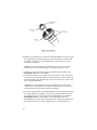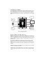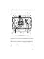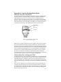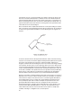
1
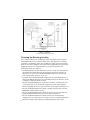
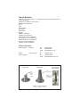
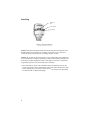
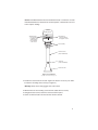
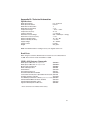
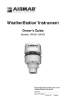
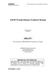
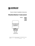
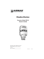
WeatherStation
Powerboat Model PB100
Owner’s Guide
Record the serial number found on the
WeatherStation for future reference.
Serial No._________________________
Date of Purchase___________________
17-426-01 r01
02/01/06
Copyright © 2005, 2006 Airmar Technology Corp. All rights reserved.
Table of Contents
Introduction
Adding External Sensors
Choosing the Mounting Location
Tools & Materials
Installing
Cable Routing & Connecting
Connecting to a Converter
Connecting to a Combiner
Connecting to a Generic NMEA Display
Installing the Software
Setting Up the WeatherCaster Program
Using the WeatherCaster Program
Maintenance & Updates
Where to Purchase Parts
Troubleshooting
Appendix A—How the WeatherStation Works
Appendix B—Technical Information
Acronyms & Glossary
4
5
6
7
8
11
11
13
23
25
30
35
43
43
44
51
57
58
3
IMPORTANT: Please read the owner’s guide
completely before proceeding with the installation.
These instructions supersede any other instructions
in your instrument manual if they differ.
Introduction
Thank you for purchasing the Airmar Ultrasonic WeatherStation. This exciting
product is actually six different sensors in a single unit—without any moving parts.
The compact housing is fully waterproof with a single removable cable. Data is
output in digital NMEA 0183 format.
Functions of the WeatherStation
• Apparent wind speed
• Apparent wind direction
• Magnetic compass heading
• Air temperature
• Relative humidity
• Dew point temperature
• Wind chill temperature
• Barometric pressure
• Global Positioning System (GPS)
• Vessel speed over ground (SOG)
• Vessel course over ground (COG)
• True wind speed
• True wind direction
• Heading relative to true north
• True wind chill temperature
• True wind speed relative to water—requires speed-through-water input
4
Adding External Sensors
The WeatherStation can receive data from external sensors when they are
connected through an optional Combiner. This device processes additional
received data and transmits it to the WeatherStation for use in true wind
calculations. The WeatherStation will automatically detect whether these sensors
are internal, external, or not available at all. Simply connect the sensor(s) to the
Combiner or other NMEA 0183 repeater hardware.
The data provided by an additional sensor(s) such as heading or water depth can
also be seen on displays connected to the Combiner.
• GPS—An external NMEA 0183 GPS can be connected instead of or in addition
to the internal GPS. The WeatherStation gives priority to valid external GPS
data when available.
• Compass—If an external electronic compass is installed and working, this
external compass data will override the WeatherStation compass.
• Speed-through-water sensor—An external speed sensor with NMEA 0183
output can be installed, such as an Airmar Smart™ Sensor. Airmar
recommends installing the DST800V to receive water depth, boat speed, and
water temperature data.
5
Min. 1m
Figure 1. Antennas
Courtesy of Northstar BNT, Acton, MA
Choosing the Mounting Location
For accurate readings and a reliable GPS signal, selecting the best location for
the WeatherStation is very important. Easy access and appearance should be
secondary considerations. Since each installation is unique, the best separation
distances from other equipment on the boat will vary depending on the particular
equipment and how it is configured. Choose a location that balances the
requirements below (see Figure 1).
• The WeatherStation must be mounted in “clear air”—away from obstructions in
any direction that will interfere with air flowing through the unit. If there is an
obstruction, be sure to mount the WeatherStation at least 2m (6') away. On
land, avoid roof tops, chimneys, trees, etc.
• If possible, mount the WeatherStation higher than any other object. Mount it a
minimum of 500mm (20") above the surrounding surfaces. For land use, mount
a minimum of 10m (33') above sea level.
• Because the WeatherStation has an electronic compass, it should be at least
1 m (3') away from any on-board radar equipment or other strong magnetic
fields from equipment such as radio transmitters, boat engines, generators, etc.
• Because the WeatherStation has a GPS, it must be lower than any on-board
INMARSAT communications antenna.
• Because the WeatherStation has a GPS, be sure it is as far as possible from
high-powered transmitting antennas to avoid mutual interference.
• Because the WeatherStation has a GPS, check for any electromagnetic
shading. That is, any obstructions from other vessels or shoreline buildings that
will interfere with the GPS signals that the WeatherStation must receive.
6
Tools & Materials
Antenna mount with standard 1” - 14 marine threads and a pass-through for the
cable (see Figure 2)
Hardware to install the antenna mount
Extension tube (optional)
Pencil
Level
Safety goggles
Dust mask
Electric drill
Drill bits
Phillips screwdrivers
Plumber’s tape (optional)
Cutting pliers (some installations)
Wire strippers (some installations)
Electrical tape (some installations)
Converter (some installations)
Combiner (some installations)
Where to Purchase
USA & Canada
Gemeco
Tel:
Fax:
email:
843.394.3565
843.394.3736
[email protected]
Europe
& Rest of World
Airmar Europe
Tel:
Fax:
email:
45.45.81.04.18
45.45.81.04.93
[email protected]
deck mount
ratchet mount
with extension
deck mount
cable
passes
through
center
of mount
cable
pass-through
extension
with cable
pass-through
Figure 2. Antenna mounts
Copyright © 2005 Airmar Technology Corp.
7
Installing
waterproof
film
wind channel
metal plate
Figure 3. The wind channel
Copyright © 2005 Airmar Technology Corp.
Caution: The blue metal plate and the blue film found in the wind channel of the
WeatherStation are essential to its operation (see Figure 3). Be careful not to
scratch the plate, puncture the film, or damage them in any way.
Caution: Do not remove the connector(s) to ease cable routing. If the cable must
be cut and spliced, use Airmar’s splash-proof Junction Box #33-035 and follow the
instructions provided. Cutting the cable or removing the connector, except when
using Airmar’s junction box, will void the sensor warranty.
1. Place the antenna mount at the selected location and mark the holes for the
screws (see Figure 2). Also, mark the hole in the center of the mount for the cable
to pass through. If you are using a ratchet mount, be sure you have purchased
an extension with a cable pass-through.
8
Caution: The WeatherStation must be installed vertically—not tilted to one side.
If the WeatherStation is tilted from the horizontal plane, it will introduce an error
in the compass reading.
WeatherStation
alignment tabs
face forward
toward the bow
and parallel to
the centerline
of the vessel
wind channel
where air travels
through the sensor
nut assembly
extension tube
(most installations)
cable exit
(some installation)
antenna mount
Figure 4. Installation
Copyright © 2005 Airmar Technology Corp.
2. Position the antenna mount at a 90º angle to the deck. If necessary, use shims
to make the mounting surface level (see Figure 4).
Warning: Always wear safety goggles and a dust mask.
3. Drill the holes for the mounting screws and the cable exit if necessary.
4. Using purchased screws, fasten the antenna mount in place.
5. Screw an extension tube onto the antenna mount if desired.
9
WeatherStation
connector
alignment
key
nut
assembly
captive
nut
Figure 5. Connecting
Copyright © 2005 Airmar Technology Corp.
6. With the nut assembly on the cable near the WeatherStation connector, thread
the cable through the extension tube (if used), antenna mount, and the cable
exit. Allow several inches of cable topped by the connector above the nut
assembly (see Figure 5).
Caution: If you use a thread lock, use plumber’s tape. Do not use a liquid
thread lock as it may weaken the plastic, causing it to swell and crack.
7. Screw the nut assembly onto the top of the antenna mount/extension tube.
Hand-tighten only. Do not over tighten.
8. Remove the protective cover from the connector. (Save the cap to protect the
connector, when the WeatherStation is removed.) Plug the 7-pin connector into
the WeatherStation. The alignment key on the connector fits into a notch in the
base of the WeatherStation.
Caution: Be sure the alignment tabs on the WeatherStation point forward
toward the bow and parallel to the centerline of the boat. This is necessary to
accurately measure wind direction and vessel heading.
9. Be sure the alignment tabs on the WeatherStation are facing forward toward the
bow and parallel to the centerline of the boat (see Figure 4). Slide the captive
nut upward and screw it onto the base of the WeatherStation (see Figure 5).
Hand-tighten only. Do not over tighten. Be careful NOT to rotate the
WeatherStation or loosen the nut assembly from the antenna mount/extension
tube. Double check to be sure the alignment tabs are still facing forward.
10
Cable Routing & Connecting
Depending on the equipment that you will be using, route the WeatherStation
cable to a Converter, a Combiner, or directly to a NMEA 0183 display. Go to the
section that is appropriate for your equipment.
Caution: Do not remove the waterproof connector(s) to ease cable routing. If the
cable must be cut and spliced, use Airmar’s splash-proof Junction Box No. 33-035
and follow the instructions provided. Cutting the cable or removing the connector,
except when using Airmar’s junction box, will void the sensor warranty.
Caution: To reduce electrical interference, separate the cables from other
electrical wiring and the engine.
Caution: Be careful not to tear the cable jackets when passing them through
bulkheads and other parts of the boat.
Caution: Coil any excess cable(s) and secure it with a zip-tie to prevent damage.
Connecting to a Converter
The Converter allows the WeatherStation measurements to be displayed on a PC
by converting the data from NMEA 0183 to USB.
power
supply
PC
WeatherStation
Figure 6. Converter Installation
Copyright © 2005 Airmar Technology Corp.
11
Mounting Location of the Converter
1. Select a convenient, dry, mounting location for the water-resistant Converter,
about 1 – 2 m (3' – 6') from the PC (see Figure 6).
2. Hold the Converter at the selected location and mark the position of the screw
holes. If the Converter will be mounted on a vertical surface, face the cables
downward to avoid water seeping into the box.
Warning: Always wear safety goggles and a dust mask.
3. At the marked locations, drill the holes for the screws. Do not fasten the
Converter in place at this time.
WeatherStation Cable
Route the WeatherStation cable to the Converter. Do not connect the
WeatherStation cable or fasten it in place at this time.
USB Cable
Route the USB cable coming from the Converter into the USB port on the PC.
Do not connect the cable or fasten it in place at this time.
Power Cable
Warning: The power panel must have a 1 amp fast-blow fuse or circuit breaker.
1. Route the power cable from the Converter to the power supply. Do not fasten the
power cable in place at this time.
2. Allowing an extra 25 cm (10") for wiring ease, cut the cable to length.
3. Strip 60mm (2-1/2") of the outer jacket and foil shielding from the cut end of the cable.
4. Cut off the bare wire flush with the cable jacket.
5. Strip 10 mm (3/8") of conductor insulation from the end of each colored wire.
6. Protect the cable’s foil shielding from causing a short by wrapping electrical
tape around the jacket where the wires emerge from the cable. The tape must
overlap the wires a minimum of 6 mm (1/4").
7. Connect the wires to the power supply (10 – 16 V and 0.5 amp required).
See the color code below.
Red
Black
12 VDC +
12 VDC –
Note: the Converter is powered by the USB port and the WeatherStation is
powered by the power cable.
Completing the Installation
1. Fasten the Converter in place with the screws supplied.
2. Plug the WeatherStation cable into the Converter.
3. Plug the USB cable into the PC.
4. Fasten all the cables in place.
LED Indicator Light
The green LED indicator light will flash when the Converter is operating.
Install the Software
Go to “Installing the Software”.
12
Connecting to a Combiner
The Combiner allows the WeatherStation data to be displayed simultaneously on
both an NMEA display and a PC. On the Combiner, the two auxiliary grommets
labeled AUX NMEA OUT can be used to connect additional devices capable of
displaying WeatherStation data (see Figure 7). All display devices must be NMEA
0183.
PC
additional
display
Airmar
Smart™ Sensor
or other sensor
Weather
Station
power
supply
additional
display
NMEA display
or additional
sensor
Figure 7. Combiner installation
Copyright © 2005 Airmar Technology Corp.
What does NMEA IN and NMEA OUT mean?
NMEA IN represents input for data flowing into a NMEA device. An IN device is a
NMEA listener. NMEA OUT signifies output for data flowing out of a device. OUT
devices are NMEA talkers. The Combiner label designates data flow as viewed by
the device itself. For example, the Combiner’s output should be connected to a
display’s input.
The output of any NMEA device (talker) may connect to the inputs of multiple
devices (listener). However, it is not permissible to connect the output of one
NMEA device to the output of another. If the need arises to provide data from the
outputs of two or more devices to the input of a given device, then a Combiner is
required.
Caution: Be sure to connect a NMEA talker to the NMEA IN terminal and NMEA
listeners to the NMEA OUT terminals.
Caution: When connecting NMEA devices to one another, the cable shield only
connects at ONE end of the cable, preferably at the device providing the NMEA
output.
13
Mounting Location of the Combiner
1. Select a convenient, dry, mounting location for the water-resistant Combiner,
about 1 – 2 m (3' – 6') from the NMEA device and the PC.
2. Hold the Combiner at the selected location and mark the position of the screw
holes. Note—If the Combiner will be mounted on a vertical surface, face the
grommets to the sides to avoid water seeping into the box.
Warning: Always wear safety goggles and a dust mask.
3. At the marked locations, drill the holes. Do not fasten the Combiner in place at
this time.
WeatherStation Cable
Route the WeatherStation cable to the Combiner. Do not connect the
WeatherStation cable or fasten it in place at this time.
USB Cable
Route the USB cable coming from the Combiner to the USB port on the PC.
Do not connect the cable or fasten it in place at this time.
NMEA Display/Additional Sensor Cable
1. Route the cable coming from the NMEA display/additional sensor to the
Combiner. Do not fasten the cable in place at this time.
2. Allowing an extra 25 cm (10") for wiring ease, cut the cable to length.
3. Remove the cover of the Combiner to expose the terminals inside
(see Figure 8).
DP
A/+ B/-
B/-
DM
ACTIVE RESEARCH LTD 2005 C
IN
NMEA
GND
USB
PWR
SHIELD
NMEA MULTIPLEXER
IN
NMEA
A/+ B/
-
+
-
+
B/- A/+
SHIELD
A/+
B/- A/+
SHIELD
WEATHER STATION
NMEA IN NMEA OUT POWER
POWER NMEA OUT NMEA IN
25-431-01
AIRMAR
NMEA DISPLAY
050818-001 ACTIS
power
cable
Figure 8. Inside the Combiner
Copyright © 2005 Airmar Technology Corp.
14
PC
cable
4. Using a small Phillips screwdriver, puncture the grommet that corresponds to
NMEA Display on the cover (see Figure 7). Be careful not to damage the circuit
board.
5. Push approximately 200mm (8") of the cable through the grommet (see
Figure 9). To ease sliding, apply alcohol to the cable jacket.
DP
USB
PWR
NMEA MULTIPLEXER
SHIELD
B/-
SHIELD
GND
WEATHER STATION
POWER
NMEA OUT NMEA IN
B/- A/+
B/- A/+
AIRMAR
25-431-01
NMEA
IN
+
DM
-
NMEA IN NMEA OUT POWER
A/+
C ACTIVE RESEARCH LTD 2005
+
-
A/+ B/-
SHIELD
A/+ B/-
NMEA
IN
NMEA DISPLAY
050818-001 ACTIS
NMEA
display
cable
power
cable
PC
cable
Figure 9. Wiring a NMEA display to the Combiner
Copyright © 2005 Airmar Technology Corp.
6. Strip 60mm (2-1/2") of the outer jacket and foil shielding from the cut end of the
cable.
7. Strip 10 mm (3/8") of conductor insulation from the end of each colored wire.
8. Protect the cable’s foil shielding from causing a short by wrapping electrical
tape around the jacket where the wires emerge from the cable. The tape must
overlap the wires a minimum of 6 mm (1/4").
9. From outside the Combiner, carefully pull the cable until only 13mm (1/2") of the
cable jacket remains inside.
15
10.Connect each wire in turn into the designated NMEA Display terminal. Loosen
the screw, insert the stripped end of the wire into the square hole, and retighten
the screw. Be sure the stripped end of the wire is inserted up to its insulation
only. Do not include any insulation inside the terminal. Gently tug on the wire to
ensure that it is securely fastened. Repeat this process until all the wires are
connected. Refer to the owner’s manual that came with the display/sensor and
the wiring diagram below (see Figure 10).
DP
USB
PWR
NMEA MULTIPLEXER
SHIELD
B/-
SHIELD
GND
WEATHER STATION
POWER
NMEA OUT NMEA IN
B/- A/+
B/- A/+
AIRMAR
25-431-01
NMEA
IN
+
DM
-
NMEA IN NMEA OUT POWER
A/+
C ACTIVE RESEARCH LTD 2005
+
-
A/+ B/-
SHIELD
A/+ B/-
NMEA
IN
NMEA DISPLAY
050818-001 ACTIS
See the NMEA display manual
for power and shield connections.
-
+
B/- A/+
B/- A/+
NMEA IN
NMEA OUT POWER
SHIELD
Note: Power is available from
the Combiner as shown by
the dashed lines.
Figure 10. Wiring diagram to connect a NMEA display
Copyright © 2005 Airmar Technology Corp.
16
Auxiliary NMEA IN Grommet.
Use the AUX NMEA IN grommet to connect an external NMEA 0183 sensor such
as: an Airmar Smart™ Sensor, an external GPS, an external compass, or other
sensor. An “IN” device will supply additional data to the WeatherStation.
The WeatherStation software (WeatherCaster) will automatically detect a Smart™
Sensor and display the appropriate data. Airmar recommends installing the
DST800V to receive water depth, boat speed, and water temperature data. Other
Smart™ Sensors can be connected, provided that your NMEA display can read
the sentence output and is configured to display those values.
The AUX NMEA IN grommet can also be used to connect an external GPS. In
some cases, a GPS receiver can be plugged directly into a NMEA port on the
display, if it can repeat the input to the Combiner. This would leave the AUX NMEA
IN grommet on the Combiner free to connect an Airmar Smart™ Sensor.
To wire a device through the AUX NMEA IN grommet, use the NMEA IN terminals
on the printed circuit board (see Figure 11).
DP
USB
PWR
NMEA MULTIPLEXER
SHIELD
B/-
SHIELD
GND
WEATHER STATION
POWER
NMEA OUT NMEA IN
B/- A/+
B/- A/+
AIRMAR
25-431-01
NMEA
IN
+
DM
-
NMEA IN NMEA OUT POWER
A/+
C ACTIVE RESEARCH LTD 2005
+
-
A/+ B/-
SHIELD
A/+ B/-
NMEA
IN
NMEA DISPLAY
050818-001 ACTIS
NEMA
display
cable
power
cable
external
sensor
cable
PC
cable
Figure 11. Wiring an external sensor to the Combiner
Copyright © 2005 Airmar Technology Corp.
17
1. Route the cable coming from the external sensor to the Combiner. Do not fasten
the cable in place at this time.
2. Allowing an extra 25 cm (10") for wiring ease, cut the cable to length.
3. Remove the cover of the Combiner to expose the terminals inside (see
Figure 11). Using a small Phillips screwdriver, puncture the grommet that
corresponds to AUX NMEA IN on the cover (see Figure 7). Be careful not to
damage the circuit board.
4. Push approximately 200mm (8") of the cable through the grommet (see Figure 11).
5. Strip 60mm (2-1/2") of the outer jacket and foil shielding from the cut end of the cable.
6. Strip 10 mm (3/8") of conductor insulation from the end of each colored wire.
7. Protect the cable’s foil shielding from causing a short by wrapping electrical
tape around the jacket where the wires emerge from the cable. The tape must
overlap the wires a minimum of 6 mm (1/4").
8. From outside the Combiner, carefully pull the cable until only 13mm (1/2") of the
cable jacket remains inside.
18
9. Connect each wire in turn into the designated NMEA IN terminal. Loosen the
screw, insert the stripped end of the wire into the square hole and retighten the
screw. Be sure the stripped end of the wire is inserted up to its insulation only.
Do not include any insulation inside the terminal. Gently tug on the wire to
ensure that it is securely fastened. Repeat this process until all the wires are
connected. Refer to the owner’s manual that came with the sensor and the
wiring diagram below (see Figure 12).
DP
PWR
NMEA MULTIPLEXER
SHIELD
B/-
SHIELD
GND
USB
WEATHER STATION
NMEA OUT NMEA IN
POWER
B/- A/+
B/- A/+
AIRMAR
25-431-01
NMEA
IN
+
DM
-
NMEA IN NMEA OUT POWER
A/+
C ACTIVE RESEARCH LTD 2005
+
-
A/+ B/-
SHIELD
A/+ B/-
NMEA
IN
NMEA DISPLAY
050818-001 ACTIS
See the NMEA display manual
for power and shield connections.
-
+
B/- A/+
NMEA OUT POWER
SHIELD
Note: Power is available from
the Combiner as shown by
the dashed lines.
Figure 12. Wiring diagram to connect an external sensor
Copyright © 2005 Airmar Technology Corp.
19
Auxiliary NMEA OUT Grommets
Use the AUX NMEA OUT grommets to connect one or two additional devices to
receive and display data from the WeatherStation. To wire a device(s) through the
AUX NMEA OUT grommet(s), use the NMEA OUT terminals on the printed circuit
board (see Figure 13).
Note: If you will be connecting two devices, wire both devices to the same
designated terminals—on top of one another.
additional
display
cable
additional
display
grommet
DP
USB
PWR
NMEA MULTIPLEXER
SHIELD
B/-
SHIELD
GND
WEATHER STATION
POWER
NMEA OUT NMEA IN
B/- A/+
B/- A/+
AIRMAR
25-431-01
NMEA
IN
+
DM
-
NMEA IN NMEA OUT POWER
A/+
C ACTIVE RESEARCH LTD 2005
+
-
A/+ B/-
SHIELD
A/+ B/-
NMEA
IN
NMEA DISPLAY
050818-001 ACTIS
NMEA
display
cable
power
cable
PC
cable
Figure 13. Wiring additional display devices to the Combiner
Copyright © 2005 Airmar Technology Corp.
1. Route the cable coming from the additional display device(s) to the Combiner.
Do not fasten the cable in place at this time.
2. Allowing an extra 25 cm (10") for wiring ease, cut the cable to length.
3. Remove the cover of the Combiner to expose the terminals inside.
4. Using a small Phillips screwdriver, puncture the grommet(s) that corresponds to
AUX NMEA OUT on the cover (see Figure 7). Be careful not to damage the
circuit board.
20
5. Push approximately 200mm (8") of the cable through the grommet(s) (see Figure 13).
6. Strip 60mm (2-1/2") of the outer jacket and foil shielding from the cut end of the
cable (s).
7. Strip 10 mm (3/8") of conductor insulation from the end of each colored wire.
8. Protect the cable’s foil shielding from causing a short by wrapping electrical
tape around the jacket where the wires emerge from the cable. The tape must
overlap the wires a minimum of 6 mm (1/4").
9. From outside the Combiner, carefully pull the cable until only 13mm (1/2") of the
cable jacket remains inside.
10.Fasten each wire in turn into the designated AUX NMEA OUT terminal. Loosen
the screw, insert the stripped end of the wire into the square hole and retighten
the screw. Be sure the stripped end of the wire is inserted up to its insulation
only. Do not include any insulation inside the terminal. Gently tug on the wire to
ensure that it is securely fastened. Repeat this process until all the wires are
connected. Refer to the owner’s manual that came with the display/sensor and
the wiring diagram below (see Figure 14).
NMEA
POWER
IN
A/+ B/- - +
SHIELD
See the NMEA display manual
for power and shield connections.
Note: Power is available from
the Combiner as shown by
the dashed lines.
DP
WEATHER STATION
PWR
NMEA MULTIPLEXER
SHIELD
B/-
SHIELD
GND
USB
POWER
NMEA OUT NMEA IN
B/- A/+
B/- A/+
AIRMAR
25-431-01
NMEA
IN
+
DM
-
NMEA IN NMEA OUT POWER
A/+
C ACTIVE RESEARCH LTD 2005
+
-
A/+ B/-
SHIELD
A/+ B/-
NMEA
IN
NMEA DISPLAY
050818-001 ACTIS
FIgure 14. Wiring diagram to connect additional display devices
Copyright © 2005 Airmar Technology Corp.
21
Power Cable
Warning: The power panel must have a 2 amp fast-blow fuse or circuit breaker.
1. Route the power cable from the Combiner to the power supply (see Figure 13).
Do not fasten the cable in place at this time.
2. Allowing an extra 25 cm (10") for wiring ease, cut the cable to length.
3. Strip 60mm (2-1/2") of the outer jacket and foil shielding from the cut end of the
cable (s).
4. Cut off the bare wire flush with the cable jacket.
5. Strip 10 mm (3/8") of conductor insulation from the end of each colored wire.
6. Protect the cable’s foil shielding from causing a short by wrapping electrical
tape around the jacket where the wires emerge from the cable. The tape must
overlap the wires a minimum of 6 mm (1/4").
7. Connect the wires to the power supply (10 – 16 V and 0.5 amp required).
See the color code below.
Red
Black
12 VDC +
12 VDC –
Completing the Installation
1. From outside the Combiner, carefully pull each cable until only about 13 mm (1/2")
of the cable jacket remains inside the box. This will invert the nipples to form a
watertight seal.
2. Arrange the wires neatly inside the Combiner, being sure that no bare wires are
touching.
3. Attach the Combiner cover with the screws provided.
4. Fasten the Combiner in place, using the screws provided.
5. Plug the WeatherStation connector into the designated WeatherStation port on
the Combiner.
6. Plug the USB cable from the Combiner into the USB port on the PC.
7. Fasten all the cables in place.
LED Indicator Light
The green LED indicator light will be flashing when the Combiner is operating.
Install the Software
Go to “Installing the Software”.
22
Connecting to a Generic NMEA 0183 Display
1. Route the WeatherStation cable to the display. Do not fasten the cable in place
at this time.
2. Connect the WeatherStation to the display.
• Connector—If your WeatherStation came with a connector, and it can be
plugged into the port on your NMEA 0183 display, do so now. Coil any excess
cable and secure it with a zip-tie to prevent damage. Fasten the cable in place.
• No connector—If your WeatherStation does not have a connector on the
display end, it must be hard wired. Follow “Guidelines for Making Connections”
to prepare the cable. Refer to the owner’s manual that came with your display
and connect the colored wires as shown in the table below and Figure 15.
WeatherStation
Function
WeatherStation Cable
Display Function
NMEA input A/+
Yellow
NMEA output A/+ (see Note 2)
NMEA input B/–
Orange
NMEA output B/–
NMEA output A/+
White
NMEA input A/+
NMEA output B/–
Blue
NMEA input B/–
12 VDC +
Red (see Note 1)
12 VDC + (see Note 3)
12 VDC –
Black
12 VDC –
Shield
Bare
Shield
Note 1: The WeatherStation must be supplied with 12 VDC+ at 0.5 amp
between the red and black leads.
Note 2: If your display does not have NMEA output connections, the yellow and
orange wires are not needed and their ends should be taped separately.
(Alternatively, yellow and orange wires can be connected to an external sensor.)
Note 3: The display power may be wired directly to the WeatherStation cable, or
it may be wired separately.
23
Figure 15. Wiring diagram to connect to a generic NMEA display
Copyright © 2005 Airmar Technology Corp.
Wiring
Warning: The power panel must have a 1 amp fast-blow fuse or circuit breaker.
1. Route the power cable from the WeatherStation to the power supply. Do not
fasten the power cable in place at this time.
2. Allowing an extra 25 cm (10") for wiring ease, cut the cable to length.
3. Cut off the bare wire flush with the cable jacket.
4. Strip 10 mm (3/8") of conductor insulation from the end of each colored wire.
5. Protect the cable’s foil shielding from causing a short by wrapping electrical
tape around the jacket where the wires emerge from the cable. The tape must
overlap the wires a minimum of 6 mm (1/4").
6. Connect the wires to the power supply (see Figure 15).
7. Fasten all cable in place.
8. Your installation is complete. To begin receiving weather readings, refer to the
owner’s manual that came with your display.
24
Installing the Software—Converter or Combiner Installation Only
If your installation includes a Converter or a Combiner, you will need to install the
WeatherCaster software on your PC. WeatherCaster is designed to work with
Windows™ XP.
Caution: The screen resolution must be set at 1024 x 768 pixels per square inch
for WeatherCaster to operate properly.
Installing WeatherCaster
1. Power your PC.
2. Insert the WeatherStation CD into the CD-ROM drive on your PC. The Airmar
WeatherStation CD Browser window will appear (see Figure 16).
Figure 16. Airmar WeatherStation CD Browser window
Copyright © 2005 Airmar Technology Corp.
3. Click the Install Software button. Another Airmar WeatherStation CD Browser
window will appear (see Figure 17).
Figure 17. Airmar WeatherStation CD Browser install window
Copyright © 2005 Airmar Technology Corp.
25
4. Click the Install Application button. The WeatherStation InstallShield Wizard
window will appear (see Figure 18).
Figure 18. InstallShield Wizard window
Copyright © 2005 Airmar Technology Corp.
5. Click Next to continue.
6. Accept the License Agreement, then click Next.
7. Enter a user name and organization. Click Next.
8. Verify that the destination folder is correct. Click Next.
9. Click Install. The Installing Airmar WeatherStation window will appear (see
Figure 19).
Figure 19. Installing Airmar WeatherStation window
Copyright © 2005 Airmar Technology Corp.
10. When the installation is complete, click Finish.
26
Installing the USB Serial Converter Driver
Caution: THE DRIVER INSTALLATION IS IN TWO PARTS. Both drivers must be
installed for WeatherCaster to function.
The first driver is called the USB Serial Converter. It converts the USB data
packets to a serial data stream. The second driver, called the USB SERIAL PORT
driver, makes the USB connection appear as a COM port in the Windows™
Device Manager.
Important: Be sure the WeatherStation CD is inserted into the CD-ROM drive on
your PC before the Combiner or Converter hardware is connected.
1. The Airmar WeatherStation CD Browser window will appear (see Figure 17).
Click the Install Drivers button to copy the Airmar device drivers to your PC.
2. The Hardware Installation caution window will appear (see Figure 20). The USB
Serial Converter driver is not Microsoft Windows™ certified. However, it has
been tested for stable and reliable operation. Click Continue Anyway to proceed
with the installation.
Figure 20. Hardware Installation caution window
Copyright © 2005 Airmar Technology Corp.
3. When the driver installation is complete, click Finish.
4. Power the Converter or Combiner.
5. Plug the USB cable into an open USB port on your PC.
27
6. The Found New Hardware Wizard window will appear (see Figure 21). Click the
NO, not this time button to allow the driver installation.
Figure 21. Found New Hardware Wizard window
Copyright © 2005 Airmar Technology Corp.
7. Click Next to continue.
8. Another “Found New Hardware Wizard” window will appear (see Figure 22).
Click the Install the software automatically button.
Figure 22. Found New Hardware Wizard window continued
Copyright © 2005 Airmar Technology Corp.
9. Click Next to continue. The drivers will begin to install.
10.The Hardware Installation caution window will appear (see Figure 20). The
USB Serial Converter driver is not Microsoft Windows™ certified. However, it
has been tested for stable and reliable operation. Click Continue Anyway to
complete the installation.
28
11.The USB Serial Converter driver is being installed (see Figure 23). Click Finish
and wait for the Found New Hardware Wizard window to appear again.
Figure 23. Completing the Found New Hardware Wizard window
Copyright © 2005 Airmar Technology Corp.
IMPORTANT: THE NEW HARDWARE WIZARD MUST RUN TWICE FOR A
COMPLETE INSTALLATION.
Installing the COM Port Driver
1. When the Found New Hardware Wizard window appears again, it will guide you
through the USB Serial Port driver installation (see Figure 21). Repeat steps 5
through 10.
2. Click Finish to complete the installation. When the installation is complete, “Your
new hardware is installed and ready to use” icon will appear in the bottom right
corner of your screen (see Figure 24).
Figure 24. “Your new hardware is installed and ready to use” icon
Copyright © 2005 Airmar Technology Corp.
3. Close the browser window. Eject the WeatherStation CD and store it in a safe
place.
29
Setting Up WeatherCaster
After WeatherCaster is successfully installed, click the WeatherStation icon on
your PC’s desktop. When WeatherCaster opens, you will see a setup page with
gauges in the middle and dials on the left and right sides (see Figure 25). The
center gauges display the data being sent from the WeatherStation in both analog
and digital format. The dials on the sides are settings that can be changed by the
user. This page is for setup only.
Figure 25. Setup Page
Copyright © 2005 Airmar Technology Corp.
Settings
Wind Speed Setting Dial
This dial allows you to display wind speed
in the following units of measure.
•MPH—Miles Per Hour
•Knots—1 Knot = 1.15 Miles Per Hour
•KPH—Kilometers Per Hour
To change the setting, click the text to the
right of the dial.
30
Background Color Dial
This dial allows you to choose the
background color of the screen.
•Steel
•Burled Wood
•Fiberglass
To change the setting, click the text to the
right of the dial.
Temperature Setting Dial
This dial allows you to display all of the
temperature readings in the following
units of measure.
•Fahrenheit
•Celsius
To change the setting, click the text to the
right of the dial.
Compass Orientation Dial
This dial allows you to orient the
compass display one of two ways.
•North Up—The traditional orientation in
which north is displayed at the top of the
compass.
•Bow Up—This orientation will provide
wind readings relative to the bow of the
boat. The compass will display 0 – 180º
on the port side from bow to stern. And it
will display 0 – 180º on the starboard side
from bow to stern. This setting is useful
when the vessel is underway, as it helps
determine how the wind will affect the
direction and speed of the boat.
To change the setting, click the text to the
right of the dial.
True or Magnetic North Dial
This dial allows you to set the compass
using either true or magnetic north.
•True North—the direction to the
geographic North Pole.
•Magnetic North—The direction to the
magnetic North Pole.
To change the setting, click the text to the
right of the dial.
31
Barometric Pressure Setting Dial
This dial allows you to display the
barometric pressure in the following units
of measure.
•inHg—Inches of Mercury
•mBars—Millibars
To change the setting, click the text to the
right of the dial.
Wind Chill Setting Dial
This dial allows the WeatherStation to
calculate the wind chill temperature
based on:
•Apparent wind speed
•True wind speed
To change the setting, click the text to the
right of the dial.
GMT Offset Dial
The Greenwich Mean Time (GMT) Offset
Dial allows you to change the clock, so it
displays the time in your current location.
After identifying your current Time Zone,
change the setting by clicking on the
number that corresponds to your Time
Zone.
Log Time Interval Dial
The WeatherStation saves weather data
for a set period of time. This dial allows
you to choose the length of time that data
will be saved. The log time can be
adjusted in six-hour intervals from 6 – 72
hours. To change the setting, click the
number that corresponds to the length of
time that you would like data to be save.
Exit Button
To exit WeatherCaster, click the Exit
button.
32
Data Boxes at the Top of the Screen
There are six Data Boxes that appear at the top of each page (see Figures 25, 26,
and 27). These boxes display information from the WeatherStation. Their functions
are as follows from left to right (see Figure 26):
1.
2.
3.
4.
5.
6.
Figure 26. Boxes at top of screen
Copyright © 2005 Airmar Technology Corp.
Box 1. Firmware Version
This box displays the Firmware version of the software that is installed on your PC
and in the WeatherStation.
Box 2. GPS Coordinates
This box displays your current position on the globe in latitude and longitude.
Box 3. Speed Over Ground
This box displays your speed over ground (SOG) and course over ground (COG)
which is calculated using the GPS. If you have an Airmar Smart™ Sensor
connected through an optional Combiner, it will also display water depth and
water temperature.
Box 4. Windsock True Speed Indicator
This box displays the wind speed flag icon that relates to the actual wind speed.
The flag will change as the wind speed increases or decreases (see Figure 27).
0–20 knots
Small Craft
Warning
Gale Warning
Tropical Storm
Warning
Hurricane
Warning
Figure 27. Wind speed flags
Copyright © 2005 Airmar Technology Corp.
33
Box 5. GPS Connection Indicator
This icon indicates if the GPS inside the WeatherStation has a satellite fix. When
the icon is red, there is no GPS fix. When the icon is blue, there is a GPS fix.
Box 6. Freezing Point Indicator
This icon will display how close the actual temperature is relative to the freezing
point.
Previous Page Arrow
This returns you to the previous screen.
(WeatherCaster has three pages.) To
change the display page, click the arrow.
Next Page Arrow
This moves you to the next screen,
minimizes the screen, or exits
WeatherCaster. To change the display
page, click the arrow.
Click the Next Page arrow to continue.
34
Using the WeatherCaster Program
WeatherCaster has three pages/display screens. To move between pages, click
the Next Page or Prev Page arrow.
• Setup Page—This page contains gauges in the center and dials on the sides.
The dials are settings that can be changed by the user (see Figure 25).
• Analog Gauge Screen—This page displays the data being sent from the
WeatherStation on gauges in both analog and digital format (see Figure 28).
After setup is completed, this page will display automatically when the
WeatherStation program is launched.
• Large Compass and Digital Readout Page—This page displays a large
compass on the left and weather readings in digital format on the right (see
Figure 29).
Analog Gauge Screen
After WeatherCaster has been setup, the next time you start the WeatherStation
program an Analog Gauge Screen will appear (see Figure 28). The gauges
display the data being sent from the WeatherStation. Each gauge displays data in
both analog and digital format.
Figure 28. Analog gauge screen
Copyright © 2005 Airmar Technology Corp.
35
High and Low Readings
Some gauges display a colored arc. A blue arc shows the lowest reading in a 24
hour period. A red arc show the highest reading in a 24 hour period. And white
space between a blue and a red arc show the range of the reading in a 24 hour
period. Blue and red lines may appear on all gages except the Compass,
Barometer, and Clock
Displaying Historical Data
You can view historical data for each gauge except the compass and the clock.
When you click on a gauge, a graph will appear. The graph displays time at the
bottom and the unit of measure on the left. A red line will indicate the history.
Gauges
Note: The True Wind Relative to Water and the Water Speed gauges will appear
only if an Airmar Smart™ Sensor is installed and connected through an optional
Combiner.
Wind Chill Gauge
This gauge uses a needle to
indicate the wind chill temperature
as well as a digital readout at the
bottom. To view historical wind chill
data, c lick the gauge. A graph will
appear as shown on the right. To
return to the Wind Chill Gauge,
click the graph.
Note: The wind chill temperature is
calculated only when the air
temperature is less than 10ºC
(50ºF) and the wind speed is
greater than 2.6Kn (3MPH).
Air Temperature Gauge
This gauge uses a needle to
indicate the air temperature as
well as a digital readout at the
bottom. To view historical air
temperature data, click the gauge.
A graph will appear as shown on
the right. To return to the Air
Temperature Gauge, click the
graph.
36
Apparent Wind Gauge
This gauge uses needles to
indicate the apparent wind speed
and direction. The long needle
points to the wind speed, and the
short needle points to the wind
direction. There is also a digital
readout at the bottom. To view
historical apparent wind speed
data, click the gauge. A graph will
appear as shown on the right. To
return to the Apparent Wind
Gauge, click the graph.
True Wind Gauge
This gauge uses needles to
indicate the true wind speed and
direction. The long needle points
to the wind speed, and the short
needle points to the wind direction.
There is also a digital readout at
the bottom. To view historical, true
wind speed data, click the gauge.
A graph will appear as shown
below. To return to the True Wind
Gauge, click the graph.
37
Compass
The Compass displays true and apparent wind direction along with vessel
heading. The Compass does not collect historical data.
• Apparent wind direction is indicated by a black needle and a black digital
readout on the left of the gauge.
• True wind direction is indicated by a red needle and a red digital readout on
the right of the gauge.
• Vessel heading is displayed as a blue boat icon in the center of the gauge
and indicates the direction in which the boat is traveling. The heading is also
digitally displayed in the lower center in blue.
Barometer
The barometer uses needles to indicate the barometric pressure. The long black
needle indicates barometric pressure, and the short red needle indicates the
forecast. Near the bottom, is a digital readout of the barometric pressure. To view
historical barometric readings, click the gauge. A graph will appear as shown on
the right. To return to the Barometer, click the graph.
38
Relative Humidity Gauge
This gauge uses a needle to
indicate the relative humidity as a
percentage. There is also a digital
readout at the bottom. To view
historical humidity data, click the
gauge. A graph will appear as
shown on the right. To return to the
Relative Humidity Gauge, click the
graph.
Dew Point Gauge
This gauge uses a needle to
indicate the dew point
temperature. There is also a digital
readout at the bottom. To view
historical dew point data, click the
gauge. A graph will appear as
shown on the right. To return to the
Dew Point Gauge, click graph.
GPS Satellites
This gauge uses a needle to
indicate the number of satellites
that the internal WeatherStation
GPS is tracking. There is also a
digital readout at the bottom. To
view historical GPS data, click the
gauge. A graph will appear as
shown on the right. To return to the
GPS Satellite Gauge, click the
graph.
Note: Four or more satellites
usually indicates a 3D fix.
39
True Wind Speed Relative to
Speed Through Water
This gauge will appear only if you
have installed a paddlewheel
sensor measuring boat speed
through the water, and the sensor
is connected to an optional
Combiner. True wind speed
relative to speed through water
cannot be calculated using GPS
readings.
This gauge uses needles to
indicate true wind speed and
direction relative to speed through
water. The long needle points to
the wind speed, and the short
needle points to the wind direction.
There is also a digital readout at
the bottom. To view historical data,
click the gauge. A graph will
appear as shown on the right. To
return to the gauge, click the
graph.
Water Speed
This gauge will appear only if you
have installed a paddlewheel
sensor measuring boat speed
through the water, and it is
connected through an optional
Combiner. The gauge uses a
needle to indicate boat speed
through the water. There is also a
digital readout at the bottom.
To view historical water speed
data, click the gauge. A graph will
appear as shown on the right. To
return to the Water Speed Gauge,
click the graph.
40
The Large Compass and Digital Display Page
Click the Next Page arrow at the top right of the screen to go to the Large
Compass and Digital Display Page. This page shows a large compass on the left
side of the screen and weather readings in digital format on the right
(see Figure 29). This page does not display historical data.
Figure 29. Large compass and digital display page
Copyright © 2005 Airmar Technology Corp.
Compass
The Compass displays true and apparent wind direction along with vessel
heading (see Figure 29).
• Apparent wind direction is indicated by a black needle and a black digital
readout on the left of the gauge.
• True wind direction is indicated by a red needle and a red digital readout on
the right of the gauge.
• Vessel heading is displayed as a blue boat icon in the center of the gauge
and indicates the direction in which the boat is traveling. The heading is also
digitally displayed in the lower center in blue.
41
Weather Readings
The right side of the screen displays the following (see Figure 29):
•
•
•
•
•
•
•
•
•
Apparent wind speed and direction
True wind speed and direction
Air temperature
Wind chill temperature
Relative humidity
Dew point temperature
Barometric pressure
Time—Displayed in a 12 and a 24 hour format
Water speed—It will appear only if you have installed a paddlewheel sensor
measuring boat speed through the water, and it is connected through an
optional Combiner.
• True wind relative to water— It will appear only if you have installed a
paddlewheel sensor measuring boat speed through the water, and it is
connected to the Combiner.
42
Maintenance & Updates
WeatherCaster Updates
Download WeatherCaster updates from Airmar’s web site, www.airmar.com.
Calibration
The WeatherStation is calibrated at the factory and does not require any
calibration after purchase.
Maintenance
Since the WeatherStation has no moving parts, it requires minimal maintenance.
Caution: The blue metal plate and the blue waterproof film found in the wind
channel of the WeatherStation are essential to its operation (see Figure 30).
Be careful not to scratch the plate, puncture the film, or damage them in any way.
waterproof
film
wind channel
metal plate
Figure 30. The wind channel
Copyright © 2005 Airmar Technology Corp.
Keep the wind channel free of SPIDER WEBS, insects, dirt, and other debris.
Since the blue waterproof film in the wind channel protects the transducers, be
careful to keep it intact.
Where to Purchase Parts
USA & Canada
Gemeco
Tel:
Fax:
email:
843.394.3565
843.394.3736
[email protected]
Europe
& Rest of World
Airmar Europe
Tel:
Fax:
email:
45.45.81.04.18
45.45.81.04.93
[email protected]
43
Troubleshooting
•
•
•
•
•
Is there power to the WeatherStation?
Are all the connections tight?
Is the cable-run free of kinks?
Is the wiring correct?
Are there any obstructions in the wind channel of the WeatherStation? Keep it
free of spider webs, insects, dirt, and other debris. Be careful not to puncture
the blue waterproof film or scratch the blue plate.
• Is there ice on the WeatherStation?
• For a GPS fix, does the WeatherStation have a clear view of the sky?
Combiner Problems
The LED light on the Combiner indicates its current operating mode and if an error
is detected during the self-test process. See the table below.
Color and
Flash Count
Mode and
Error Condition
Description of Mode and
Required User Action
Red
No flashing
Start-up mode
No error
Normal operation mode that should last for no
more than 1.5 seconds. Any longer indicates an
error with the program. No action required.
Red
No flashing
Flash Updating mode
No error
The LED will stay red for the duration of the flash
update operation. When the operation is
complete, the Combiner will automatically reset.
No action required.
Amber
No flashing
Initialize & Self-test mode
No error
Normal operation mode that follows the start-up
mode and should last for approximately 1 second.
No action required.
Green
No flashing
Normal & No Data mode
No error
Normal operation mode that follows the Initialize
& Self-test mode. Indicates that no error was
detected during self-test.
Also, no data is currently being received by the
Combiner. No action required.
Green
Flashing
(1–10 per sec.)
Normal & Data Receive
mode
No error
Normal operation mode that indicates data is
being received by the Combiner. The flash rate is
proportional to the Baud rate. No action required.
Amber
Flashing
(1 every 4 sec.)
Error Trap mode
EEPROM memory error
An error with the EEPROM memory has been
detected during the self-test mode.
Reset the Combiner by powering down, waiting
60 sec., then restarting the Combiner.
PC Problems
If you are uncertain of the COM port on your PC, follow the steps below.
1. From the Start menu, select Control Panels.
2. Select the System option.
3. Select the Hardware tab.
4. Select Device Manager.
5. Select Ports.
6. Select Airmar NMEA 0183 – USB Converter.
The Converter is powered when it is connected to the USB port on the PC.
44
WeatherCaster Software Problems
Identify the WeatherCaster Version
The WeatherCaster version number is located on the top left corner of each
WeatherCaster page. The latest version of WeatherCaster is available for
download at www.airmar.com.
Setting the Display Resolution to 1024 X 768
When using WeatherCaster on a computer with a display resolution less than
1024 x 768 (e.g. 800x600), the window will be truncated on the right side and
bottom edges. The EXIT controls will therefore be hidden from view. If this
happens, you can exit WeatherCaster by pressing the key combination <alt>-F4
(i.e. while pressing and holding the Alt key, press and release the F4 key). If the
display resolution is greater than 1024 X 768 (e.g. 1280 x 1024), WeatherCaster
will not fill the entire PC screen. You will need to set your monitor resolution to
1024 x 768 in order to use WeatherCaster.
1. From the Start menu, select Control Panels.
2. Select Display Properties.
3. Select the Settings tab.
4. Slide the Screen Resolution indicator until 1024 X 768 is selected.
5. Click the Apply button, then click Yes.
45
Auto-Detecting COM Ports
If you install more than one instance of the drivers for the Combiner/Converter,
WeatherCaster may not automatically detect the appropriate COM port. In this
case, you will need to manually select the COM port and the baud rate upon
launching WeatherCaster.
Manually selecting the COM port and baud rate
1. After launching WeatherCaster, you will see the screen below.
Click Cancel.
2. You will then see the screen below. Click Yes to manually set the COM port and
baud rate.
3. In the Manual Communications Port Setup window, select the appropriate COM
port from the Comm. Port drop-down menu. Be sure to select the Comm. Port
46
that matches the COM port shown in brackets on the Auto-Detecting
WeatherStation Data window.
4. Select the appropriate Baud Rate from the drop-down menu.
• If you have a: USB Converter, set the baud rate to 4800.
• If you have a Combiner, set the baud rate to 57600.
5. Click OK, and WeatherCaster will start.
6. Exit WeatherCaster; then start the program again.
The next time WeatherCaster runs, it will automatically select the proper
COM port.
Double Digit COM Ports
If there are more than nine COM ports assigned to your computer, the
WeatherStation may not auto-detect WeatherCaster.
Manually select a specific COM port.
1. From the Start menu, select Control Panel.
2. Select the System option.
3. Select the Hardware tab.
4. Select Device Manager.
5. Select Ports.
6. Right click Airmar Port and select Properties.
7. Select the Port Settings tab.
8. Select the Advanced button.
9. From the COM Ports drop-down menu, select a single digit COM port that is not
in use and click OK.
10.Close all open windows.
47
1. Launch WeatherCaster again. You will see the screen below. Click Cancel.
2. You will then see the screen below. Click Yes to manually set the COM port and
baud rate.
3. In the Manual Communications Port Setup window, select the appropriate COM
port from the Comm. Port drop-down menu. Be sure to select the Comm. Port
that matches the COM port shown in brackets on the Auto-Detecting
WeatherStation Data window.
48
4. Select the appropriate Baud Rate from the drop-down menu.
• If you have a: USB Converter, set the baud rate to 4800.
• If you have a Combiner, set the baud rate to 57600.
5. Click OK, and WeatherCaster will start.
6. Exit WeatherCaster; then start the program again.
The next time WeatherCaster runs, it will automatically select the proper
COM port.
Troubleshooting WeatherStation Data Using Windows HyperTerminal
Important: Before starting HyperTerminal, note the COM Port number that
the WeatherStation is connected to. The COM Port number is found on the
Auto-Detecting WeatherStation Data window when WeatherCaster begins.
Important: You must close WeatherCaster to use HyperTerminal with the
WeatherStation.
1. From the Start menu, select All Programs, Accessories, Communications.
Click HyperTerminal
2. Enter an area code if prompted.
3. Select File, then New Connection.
4. Name the connection, then click OK.
5. Select the particular COM port that the WeatherStation is connected to, then
click OK.
49
6. Set the bits-per-second to 4800. Do not change any other selection. Click OK.
You will see the data sentences from the WeatherStation scrolling on the
screen, similar to the example below.
To identify the sentence commands, refer to the Technical Manual on the
WeatherStation CD.
The data can be saved by going to the File drop-down menu and selecting
Save As.
50
Appendix A—How the WeatherStation Works
About the Ultrasonic Wind Sensor
The ultrasonic wind sensor (an ultrasonic anemometer) measures apparent wind
speed and direction. The WeatherStation contains four ultrasonic transducers,
visible through the four holes in the top of the sensor’s wind channel (see
Figure 31). These transducers operate in pairs—one transducer injects a pulse
into the air, and the other (directly opposite to it) listens for the arrival of that pulse.
Each pulse bounces off the metal plate at the bottom of the wind channel and is
carried by the wind to arrive at the opposing transducer a short time later.
transducer (4)
behind waterproof
film
wind channel
metal plate
Figure 31. The ultrasonic wind sensor
Copyright © 2005 Airmar Technology Corp.
When there is no wind, the pulse travels at the speed of sound from the sender to
the receiver. Whenever the wind is blowing in that direction, the pulse will arrive
sooner than if the air is still. Similarly, whenever the wind is blowing in the opposite
direction, the pulse will arrive later than if the air is still. The four transducers take
turns in sending and receiving pulses to cover all eventualities of wind direction.
A microprocessor within the WeatherStation then combines the measurements
from all four transducers to calculate the resultant wind speed and direction.
Throughout this process, the sensor monitors the air temperature, to compensate
for the fact that the speed of sound in air changes with temperature.
Understanding True and Apparent Wind
The WeatherStation has the unique ability to display both true and apparent wind.
True wind is the actual motion of the air relative to the earth. Apparent wind is the
wind which an observer experiences while moving or on-board a boat. It is the
result of two motions—the actual motion of the air (the true wind) and the motion
of the boat. If the vessel is not moving, then the true and apparent wind will be the
same.
There are two components to any wind measurement: speed and direction. By
convention, the wind direction is an angle representing the direction from which
the wind is blowing. Sometimes this angle is referenced to true or magnetic north,
and sometimes it is referenced to the bow of the vessel. Both true and apparent
wind use these same references.
51
Consider the case of a vessel proceeding at a speed of 15 knots in calm air. An
observer on-board would experience a wind of 15 knots from dead ahead. This
apparent wind would be due solely to the motion of the boat. If a true wind of 15
knots was blowing from the stern, an observer would experience dead calm—no
apparent wind. That is because the boat is moving at the same speed and in the
same direction as the surrounding air.
Now, consider the more complicated situation of a vessel proceeding at 15 knots
with a true wind of 15 knots blowing from the side (see Figure 32). To an observer
on-board, the apparent wind would be 21.2 knots blowing from an angle 45º off
the bow.
15 knots
COG
21.2 knots
apparent wind
15 knots
true wind
Figure 32. Apparent wind
Copyright © 2005 Airmar Technology Corp.
In order to calculate the true wind speed and direction when on board a moving
vessel, it is necessary to know the apparent wind speed and direction, the speed
and course over ground of the vessel, the compass heading, and the local
magnetic variation. Note that heading and course are not the same thing: heading
is the direction the bow of the vessel is pointing, while course is the direction the
vessel is traveling. Heading and course may differ due to the effects of wind and
current. The WeatherStation can provide true wind speed and direction only if all
of the data is available. The speed and course over ground must be provided by a
GPS receiver––either built-in or networked. The heading may be provided by
either the built-in electronic compass or by an external networked compass.
Because true wind is calculated using the data from several sensors, its accuracy
depends on the accuracy of all the raw data used in the calculation. For instance,
if the electronic compass is located near iron or a similar magnetic disturbance,
the heading will be incorrect, and the true wind calculation will therefore be in
error, perhaps by quite a bit. In another example, the speed and course over
ground provided by the GPS receiver are averaged over time. If the boat is
performing maneuvers, changing speed and/or direction, then it will take a few
seconds for the SOG and COG values to "catch up". The reported true wind
values will therefore also be incorrect until the vessel reaches a steady-state
condition, traveling in a straight line at a constant speed.
52
About the Electronic Compass
The WeatherStation includes a pair of magnetoinductive sensors that measure
magnetic field strength in two axes on the horizontal plane of the WeatherStation.
From these measurements, it calculates the resultant magnetic heading angle,
thereby providing a built-in electronic compass.
Like all magnetic compasses, the WeatherStation compass will be affected by any
ferrous or magnetic materials in the vicinity, such as metal structures, motors,
speakers, etc. It will also be affected by nearby electric fields, such as the wiring
for navigation lights or radar domes. These nearby sources of magnetic
interference will distort the magnetic field and produce errors in the compass
heading. These errors are known as magnetic deviation.
Although the WeatherStation compass is a 2-axis device, the earth's magnetic
field occurs in three dimensions. That is, part of the earth's magnetic field is
oriented in the vertical direction. The closer one's location is to the north or south
pole, the stronger this vertical component becomes in comparison to the
horizontal components. The effect this has on the WeatherStation is to introduce
an error in the compass reading if the WeatherStation is tilted from the horizontal
plane. Therefore, it is important when installing the WeatherStation to ensure the
support pole is mounted vertically, and not tilted to one side. Also, keep in mind
that when your vessel experiences pitch and roll, the compass heading will be
affected accordingly.
Because the compass heading is used in the calculations for true wind, any errors
in the compass heading will also produce errors in the reported true wind speed
and direction.
If you have another electronic compass on board your vessel that is capable of
providing the NMEA 0183 HDG sentence, you can connect the output from this
external compass to the NMEA input on the WeatherStation (or to the optional
Combiner), and the data from the external compass will override the data from the
built-in compass for the purpose of calculating true wind speed and direction.
About Magnetic Variation and True Heading
The earth acts like a giant magnet, with a magnetic north pole and a magnetic
south pole. The axis of the magnetic poles is offset approximately 11.5° from the
axis of the earth's rotation. Therefore, the earth's magnetic north and south poles
are in different locations than the earth's geographic north and south poles. In
addition, the earth's magnetic field is non-uniform, and changes over time.
Magnetic variation, also known as magnetic declination, is the angle between
magnetic north and true (or geographic) north, at the observer's current location.
A magnetic compass measures heading with respect to magnetic north. To
convert this magnetic heading to true heading (that is, heading with respect to true
north), the magnetic variation must be added to the measured magnetic heading
value.
Because magnetic variation changes with location and gradually over time, it is
necessary to calculate the magnetic variation using the user's present position
and the current date. Therefore it is necessary to have a GPS with a fix in order to
provide magnetic variation and heading with respect to true north.
53
About the Air Temperature Sensor
The WeatherStation includes a built-in negative temperature coefficient thermistor
that measures the ambient air temperature. This NTC thermistor is located in a
thermally isolated region of the WeatherStation housing that is open to the
outside air.
About the Relative Humidity Sensor
The WeatherStation contains a capacitive cell humidity sensor that measures the
relative humidity of the air. Humidity refers to the amount of water vapor in the air.
Relative humidity is the percentage of saturation of the water vapor in the air. It is
the ratio of the moisture content of the air to the saturated moisture level at the
same temperature and pressure.
About Dew Point
Dew point is the temperature at which the water vapor in the air begins to
condense into a liquid. If the air were gradually cooled while maintaining constant
moisture content, the relative humidity would rise until it reaches 100%. The air
temperature at this point of saturation is called the dew point.
If the air is dry enough, it is possible to have a dew point that is below freezing.
The dew point is then sometimes referred to as the frost point.
The WeatherStation calculates dew point from the measured air temperature and
relative humidity sensor readings.
About Wind Chill Temperature
Wind Chill is a term that describes the heat loss on the human body resulting from
the combined effects of low temperature and wind. As wind speed increases, heat
is carried away from the body at a faster rate, causing a reduction in skin
temperature. Because the face is the part of the human body that is most likely to
be exposed, the wind chill index is adjusted for the average adult face.
The concept of wind chill does not apply to inanimate objects, such as a boat. The
only effect that wind chill has in this case is to shorten the time it takes the object
to cool to the actual air temperature––wind chill does not cause an object to cool
below that temperature. For example, fresh water freezes at 0°C (32°F)
regardless of what the wind chill is.
The WeatherStation calculates two values for wind chill temperature: one using
the apparent wind speed, and one using the true wind speed. The apparent wind
chill temperature is relevant to what an observer is currently experiencing on the
vessel. The true wind chill temperature indicates what the wind chill would be if the
vessel were not moving.
Wind chill temperature is only defined for temperatures at or below 10°C (50°F)
and wind speeds above 2.6 knots (3MPH).
By default, transmission of wind chill data is disabled by the WeatherStation.
When used with WeatherCaster, the wind chill data will be automatically enabled.
54
About the Barometric Pressure Sensor
The WeatherStation contains a temperature-compensated silicon piezoresistive
pressure sensor. It measures atmospheric pressure for use as a digital barometer.
While a single measurement of air pressure at a given location has little value, the
trend of changing pressure and wind over time can be a useful tool in performing
basic weather forecasting.
About the GPS
Some WeatherStations have a built-in Global Positioning System with their own
antenna, receiver, and position determining electronics. The GPS receiver
receives radio signals from a constellation of orbiting satellites maintained by the
U.S. government. By accurately measuring the time it takes for a transmission to
travel from each satellite to the receiver, the unit is able to determine the distance
between the satellite and the receiver. When the distance is known to three
satellites, the unit is able to calculate the latitude and longitude of the receiver.
This is known as a 2D fix. If the distance is known to four or more satellites, then
the unit is additionally able to calculate the altitude of the receiver. This is known
as a 3D fix.
The GPS receiver in the WeatherStation takes approximately 1 minute on average
to achieve a position fix after power is first applied. This is known as the "time to
first fix."
The GPS receiver synchronizes itself to the atomic clocks on board each satellite.
This allows the GPS receiver to accurately determine the date and time as well.
If the GPS receiver is mounted on a moving vessel, its changing position over time
allows the speed and course over ground to be calculated. The course reported by
a GPS is always with respect to true north.
The ability of the WeatherStation to calculate true wind speed and direction
depends on the presence of a GPS fix. If the GPS receiver is not tracking at least
three satellites, then the WeatherStation will be unable to provide true wind data.
(Apparent wind data should always be available, regardless of the status of the
GPS receiver.)
Certain models of the WeatherStation do not include a built-in GPS receiver. In
this case, if the true wind capabilities of the WeatherStation are desired, it will be
necessary to connect the output from an external NMEA 0183-capable GPS to
the NMEA input on the WeatherStation (or to the optional Combiner), in order to
enable the true wind capabilities of the WeatherStation.
Even if your WeatherStation includes a built-in GPS receiver, you may wish to use
a separate external GPS receiver instead, for the determination of true wind. If the
WeatherStation receives speed over ground and course over ground (SOG and
COG) data on its NMEA input from an external GPS, these data will override the
data from the built-in GPS for the purpose of calculating true wind speed and
direction. In addition, the WeatherStation will automatically suppress transmission
of GPS messages from its own built-in GPS receiver.
55
About True Wind Relative to Water
If a fix from a GPS receiver is not available, it is still possible for the
WeatherStation to determine a value for true wind, if the speed of the vessel
through the water is known. In this case, it is necessary that a water speed sensor
with an NMEA output (such as an Airmar® Smart™ Sensor) be connected to the
NMEA input on the WeatherStation (or to the optional Combiner).
The WeatherStation's calculation for true wind relative to water makes the
significant simplifying assumption that the vessel's course is the same as its
heading. That is, the effects of wind and current on the motion of the boat are
ignored. The direction of the true wind relative to water is referenced only to the
bow of the vessel, not to true or magnetic north.
56
Appendix B—Technical Information
Specifications
Wind Speed Range
Wind Speed Resolution
Wind Direction Resolution
Wind Direction Sensitivity
Temperature Range
Temperature Accuracy
Compass Sensing
Barometric Pressure Range
Barometric Pressure Accuracy
Relative Humidity Range
Relative Humidity Accuracy
Supply Voltage
Supply Current
Weight
0.5 – 99.5knots
0.1knot
1º
± 1.5º
– 30ºC – +50ºC
±1.5ºC
± 1º typically
850 – 1150mb (25" – 34"Hg)
± 1.5%
10 – 95% RH
± 5% RH
10 – 16VDC
0.5 amp
285 grams
Note: The WeatherStation’s reading accuracy can degrade below 0º C.
Baud Rates
When using the Combiner, WeatherCaster needs to be set to a Baud Rate of
57,600. The Converter needs a Baud Rate of 4,800.
NMEA 0183 Sentence Commands
Wind Speed & Direction with respect to bow
Wind Speed & Direction with respect to North
Meteorological Composite
Wind Chill Temperature
GPS Fix Data
Geographic Position L/L
Recommended Minimum GNSS
Course Over Ground (COG) & Speed Over Ground (SOG)
Heading, Deviation, Variation
True Wind Speed Relative to Water (speed sensor needed)
Standard GNSS DOP and Active Satellites
Standard GNSS Satellites in View
Apparent Wind Speed and Direction
$WIMWV *
$WIMWD *
$WIMDA *
$WIXDR
$GPGGA
$GPGLL
$GPRMC *
$GPVTG
$HCHDG
$WIVWT *
$GPGSA
$GPGSV
$WIVWR
* These sentences are enabled at the factory.
57
Additional Data Available from the WeatherStation
There are parameters that the WeatherStation can make available to the user.
Usually, more data is available from the WeatherStation than can be displayed in a
reasonable format on a screen. Also, if all the data was continuously transmitted
to the display, the update rate would be too slow and could not keep up with
WeatherStation measurements. Consequently, some parameters are transmitted
while others are not, based on a pre-selected list (the NMEA 0183 sentences with
an asterisk). Note that those parameters not transmitted are, nevertheless,
retained in the WeatherStation. For more detailed information, see the “Technical
Manual” on the WeatherStation CD.
Acronyms
CD
COG
COM Port
DOP
GNSS
GPS
LED
PC
SOG
USB
UTC
2D
3D
Compact Disk
Course Over Ground
Communications Port
Dilution Of Precision
Global Navigation Satellite System
Global Positioning System
Light Emitting Diode
Personal Computer
Speed Over Ground
Universal Serial Bus
Universal Time Coordinated
Two Dimensional
Three dimensional
Glossary
Firmware
WeatherCaster
58
The software within the WeatherStation
The user application program
59
AIRMAR
®
TECHNOLOGY CORPORATION
35 Meadowbrook Drive, Milford, New Hampshire 03055-4613, USA
www.airmar.com