1
Powercut 650
Portable Plasma Cutting System
Instruction Manual
ESAB Console Item No. 0558003179, PC-650 208/230V 1 PH CONSOLE
ESAB Console Item No. 0558003515, PC-650 208/230V 1 PH CONSOLE (BL)
ESAB Console Item No. 0558005328, PC-650 460V CONSOLE
F15-696-D
12 / 2007
Be sure this information reaches the operator.
You can get extra copies through your supplier.
caution
These INSTRUCTIONS are for experienced operators. If you are not fully familiar with the
principles of operation and safe practices for arc welding and cutting equipment, we urge
you to read our booklet, “Precautions and Safe Practices for Arc Welding, Cutting, and
Gouging,” Form 52-529. Do NOT permit untrained persons to install, operate, or maintain
this equipment. Do NOT attempt to install or operate this equipment until you have read
and fully understand these instructions. If you do not fully understand these instructions,
contact your supplier for further information. Be sure to read the Safety Precautions before installing or operating this equipment.
USER RESPONSIBILITY
This equipment will perform in conformity with the description thereof contained in this manual and accompanying labels and/or inserts when installed, operated, maintained and repaired in accordance with the instructions provided. This equipment must be checked periodically. Malfunctioning or poorly maintained equipment
should not be used. Parts that are broken, missing, worn, distorted or contaminated should be replaced immediately. Should such repair or replacement become necessary, the manufacturer recommends that a telephone
or written request for service advice be made to the Authorized Distributor from whom it was purchased.
This equipment or any of its parts should not be altered without the prior written approval of the manufacturer.
The user of this equipment shall have the sole responsibility for any malfunction which results from improper
use, faulty maintenance, damage, improper repair or alteration by anyone other than the manufacturer or a service facility designated by the manufacturer.
READ AND UNDERSTAND THE INSTRUCTION MANUAL BEFORE INSTALLING OR OPERATING.
PROTECT YOURSELF AND OTHERS!
table of contents
SECTIONTITLE...........................................................................................................................................PAGE
SECTION 1
SAFETY..............................................................................................................................................5
SECTION 2
2.0
2.1
SECTION 3
3.0
3.1
3.2
3.3
3.4
3.4.1
3.4.2
3.5
3.6
SECTION 4
4.0
4.1
4.2
4.3
INTRODUCTION................................................................................................................................................................ 7
General.................................................................................................................................................................................. 8
Scope...................................................................................................................................................................................... 8
OPERATION...................................................................................................................................................................... 15
Powercut 650 Controls...................................................................................................................................................15
Cutting with the PT-31XLPC.........................................................................................................................................17
Operating Techniques....................................................................................................................................................17
Common Cutting Problems.........................................................................................................................................19
SECTION 5
5.0
5.1
5.2
5.3
5.4
5.5
MAINTENANCE............................................................................................................................................................... 21
Inspection and Cleaning...............................................................................................................................................21
Flow Switch........................................................................................................................................................................21
Troubleshooting...............................................................................................................................................................22
Troubleshooting Guide..................................................................................................................................................23
Sequence of Operation..................................................................................................................................................27
Re-fitting the PT-31XLPC Torch...................................................................................................................................29
INSTALLATION................................................................................................................................................................... 9
General.................................................................................................................................................................................. 9
Equipment Required........................................................................................................................................................ 9
Location................................................................................................................................................................................. 9
Inspection............................................................................................................................................................................. 9
Connections.......................................................................................................................................................................10
Primary Electrical Input Connections.......................................................................................................................10
Connecting Powercut 650 for 208 Vac Input.........................................................................................................11
Secondary Connections................................................................................................................................................12
Assembling PT-31XLPC Consumable Parts............................................................................................................13
SECTION 6REPLACEMENT PARTS................................................................................................................................................ 33
6.0
General................................................................................................................................................................................33
6.1
Ordering..............................................................................................................................................................................33
table of contents
4
4&$5*0/
4"'&5:13&$"65*0/4
section
1safety
precautions
4BGFUZ1SFDBVUJPOT
6TFSTPG&4"#XFMEJOHBOEQMBTNBDVUUJOHFRVJQNFOUIBWFUIFVMUJNBUFSFTQPOTJCJMJUZGPSFOTVSJOHUIBUBOZPOF
XIPXPSLTPOPSOFBSUIFFRVJQNFOUPCTFSWFTBMMUIFSFMFWBOUTBGFUZQSFDBVUJPOT4BGFUZQSFDBVUJPOTNVTUNFFU
UIFSFRVJSFNFOUTUIBUBQQMZUPUIJTUZQFPGXFMEJOHPSQMBTNBDVUUJOHFRVJQNFOU5IFGPMMPXJOHSFDPNNFOEBUJPOT
TIPVMECFPCTFSWFEJOBEEJUJPOUPUIFTUBOEBSESFHVMBUJPOTUIBUBQQMZUPUIFXPSLQMBDF
"MMXPSLNVTUCFDBSSJFEPVUCZUSBJOFEQFSTPOOFMXFMMBDRVBJOUFEXJUIUIFPQFSBUJPOPGUIFXFMEJOHPSQMBTNB
DVUUJOHFRVJQNFOU*ODPSSFDUPQFSBUJPOPGUIFFRVJQNFOUNBZMFBEUPIB[BSEPVTTJUVBUJPOTXIJDIDBOSFTVMUJO
JOKVSZUPUIFPQFSBUPSBOEEBNBHFUPUIFFRVJQNFOU
"OZPOFXIPVTFTXFMEJOHPSQMBTNBDVUUJOHFRVJQNFOUNVTUCFGBNJMJBSXJUI
JUTPQFSBUJPO
MPDBUJPOPGFNFSHFODZTUPQT
JUTGVODUJPO
SFMFWBOUTBGFUZQSFDBVUJPOT
XFMEJOHBOEPSQMBTNBDVUUJOH
5IFPQFSBUPSNVTUFOTVSFUIBU
OPVOBVUIPSJ[FEQFSTPOTUBUJPOFEXJUIJOUIFXPSLJOHBSFBPGUIFFRVJQNFOUXIFOJUJTTUBSUFEVQ
OPPOFJTVOQSPUFDUFEXIFOUIFBSDJTTUSVDL
5IFXPSLQMBDFNVTU
CFTVJUBCMFGPSUIFQVSQPTF
CFGSFFGSPNESBGUT
1FSTPOBMTBGFUZFRVJQNFOU
"MXBZTXFBSSFDPNNFOEFEQFSTPOBMTBGFUZFRVJQNFOUTVDIBTTBGFUZHMBTTFTnBNFQSPPG
DMPUIJOHTBGFUZHMPWFT
%POPUXFBSMPPTFmUUJOHJUFNTTVDIBTTDBSWFTCSBDFMFUTSJOHTFUDXIJDIDPVMECFDPNF
USBQQFEPSDBVTFCVSOT
(FOFSBMQSFDBVUJPOT
.BLFTVSFUIFSFUVSODBCMFJTDPOOFDUFETFDVSFMZ
8PSLPOIJHIWPMUBHFFRVJQNFOUNBZPOMZCFDBSSJFEPVUCZBRVBMJmFEFMFDUSJDJBO
"QQSPQSJBUFmSFFYUJORVJTIJOHFRVJQNFOUNVTUCFDMFBSMZNBSLFEBOEDMPTFBUIBOE
-VCSJDBUJPOBOENBJOUFOBODFNVTUOPUCFDBSSJFEPVUPOUIFFRVJQNFOUEVSJOHPQFSBUJPO
5
4&$5*0/
4"'&5:13&$"65*0/4
section 1safety
precautions
8"3/*/(
8&-%*/("/%1-"4."$655*/($"/#&*/+63*06450:0634&-'"/%
05)&34 5",& 13&$"65*0/4 8)&/ 8&-%*/( 03 $655*/( "4, '03
:063 &.1-0:&34 4"'&5: 13"$5*$&4 8)*$) 4)06-% #& #"4&% 0/
."/6'"$563&34)";"3%%"5"
&-&$53*$4)0$,$BOLJMM
*OTUBMMBOEFBSUIHSPVOE
UIFXFMEJOHPSQMBTNBDVUUJOHVOJUJOBDDPSEBODFXJUIBQQMJDBCMFTUBOEBSET
%POPUUPVDIMJWFFMFDUSJDBMQBSUTPSFMFDUSPEFTXJUICBSFTLJOXFUHMPWFTPSXFUDMPUIJOH
*OTVMBUFZPVSTFMGGSPNFBSUIBOEUIFXPSLQJFDF
&OTVSFZPVSXPSLJOHTUBODFJTTBGF
'6.&4"/%("4&4$BOCFEBOHFSPVTUPIFBMUI
,FFQZPVSIFBEPVUPGUIFGVNFT
6TFWFOUJMBUJPOFYUSBDUJPOBUUIFBSDPSCPUIUPUBLFGVNFTBOEHBTFTBXBZGSPNZPVSCSFBUIJOH[POF
BOEUIFHFOFSBMBSFB
"3$3":4$BOJOKVSFFZFTBOECVSOTLJO
1SPUFDUZPVSFZFTBOECPEZ6TFUIFDPSSFDUXFMEJOHQMBTNBDVUUJOHTDSFFOBOEmMUFSMFOTBOEXFBS
QSPUFDUJWFDMPUIJOH
1SPUFDUCZTUBOEFSTXJUITVJUBCMFTDSFFOTPSDVSUBJOT
'*3&)";"3%
4QBSLTTQBUUFS
DBODBVTFmSF.BLFTVSFUIFSFGPSFUIBUUIFSFBSFOPJOnBNNBCMFNBUFSJBMTOFBSCZ
/0*4&&YDFTTJWFOPJTFDBOEBNBHFIFBSJOH
1SPUFDUZPVSFBST6TFFBSNVõTPSPUIFSIFBSJOHQSPUFDUJPO
8BSOCZTUBOEFSTPGUIFSJTL
."-'6/$5*0/$BMMGPSFYQFSUBTTJTUBODFJOUIFFWFOUPGNBMGVODUJPO
3&"%"/%6/%&345"/%5)&*/4536$5*0/."/6"-#&'03&*/45"--*/(0301&3"5*/(
1305&$5:0634&-'"/%05)&34
6
section 2
INTRODUCTION
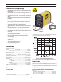
Powercut ® 650 Cutting Package
•
•
•
•
•
•
•
•
•
•
•
•
•
•
•
•
•
Manually cuts 5/8 inch and severs 3/4 inch - powerful cutting
performance
Economical price - tremendous cutting value for the
money
Compact portable design - goes to the job, easily moved
about
Delivers big machine cutting power in a rugged, lightweight
package.
Arrives ready to cut, with torch connected and front-end
parts in place, for the ultimate in operator convenience.
High frequency starting - starts through paint
Trigger lock-in for long-cut operator comfort.
Adjustable output - tailor the current to the material being
cut.
Compact simple torch - easy access, little maintenance
New quick - connect torch switch plug
New durable torch cable prevents snagging on fixtures and
materials
Patented XT nozzles - extended shape gives good visibility
as well as good consumable life
Drag or standoff cutting - easy operation with little
or no training
Template following feature - easily duplicates curves or
straight lines
Tolerates poor power lines
Three-year warranty on Console
One-year warranty on Torch
The Powercut® 650 comes out of the box ready to go! The torch is
attached with parts in place, primary cord is attached and the filter/regulator is installed. Just hook up the air, plug it in and cut.
Specifications
Cuts 5/8 in.; severs 3/4 in.
Output: 40% duty cycle.
.............................................................................
40% duty cycle
40A/120V
.
60% duty cycle............................................................................. 30A/120V
.
100% duty cycle........................................................................... 22A/120V
Output Current Range.....................................................................10 to 40 Amperes
Open Circuit Voltage......................................................................... 290 Vdc Nominal
Input @ 40A/120V............................... 208/230 vac 1 ph. 50/60 Hz., 35/32 amps
Input @ 40A/120V............................................. 460 vac 3 ph. 50/60 Hz., 8/5 amps
Power factor @ 40A Output.................................................................. 76% (1 Phase)
Efficiency @ 40A Output......................................................................... 85% (Typical)
Air requirements................................................................................250 cfh at 80 psig
Dimensions:............................................................................................................................
.
Length................................................................................. 16.00" (406mm)
.
w/ handles.................................................................... 25.70" (653mm)
.
Height.................................................................................. 16.38" (416mm)
.
Width................................................................................... 12.50" (318mm)
.
w/ Opt. torch wrap..................................................... 15.50" (394mm)
Weight (less torch & work cable).........................................................53 lbs. (24 kg)
Powercut® 650 / PT-31XLPC Cutting Performance
For a complete list of torch parts, refer to Optional Accessories .
How To Order
The Powercut® 650 comes complete with everything you need: console, 25 ft. PT-31XLPC torch, torch spare parts kit, air filter/regulator,
input power cord with plug, 25 ft. work cable with clamp. System
arrives fully assembled and ready to cut.
Torch
Ordering Information
Uses PT-31XLPC
Powercut ® 650 / 25 and 50 ft. PT-31XLPC packages
Powercut® 650,
208/230 vac 1 ph. 25 ft. PT-31XLPC.......................................... 0558003180
460 vac 3 ph. 25 ft. PT-31XLPC................................................... 0558005329
460 vac 3 ph. 50 ft. PT-31XLPC................................................... 0558005330
Instruction Literature, order number......................................................F15-696
Sales Literature, order number............................................................ PAC-21087
7
section 2
INTRODUCTION
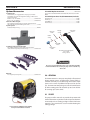
Optional Accessories
PT-31XLPC Replacement Torch.......................................... 0558003183
Torch comes assembled with Heat Shield, Nozzle, Electrode, and Swirl
Baffle.
Torch Guide Kits
The Deluxe kit, in a rugged plastic carrying case, includes
attachments for circle and straight line cutting on ferrous and
non-ferrous metals
Deluxe: 1 3/4" - 42" Radius........................................................... 0558003258
Basic: 1 3/4" - 28" Radius............................................................... 0558002675
Plasma Flow Measuring Kit
This valuable troubleshooting tool allows measurement of
the actual plasma gas flow through the torch................................. 19765
Input Receptacle
230Vac/50Amp, 3 Prong.........................................................................674540
PT-31XLPC Spare Parts Kit (P/N 0558003301) includes:
Heat Shield (1)................................................................................................... 20282
Nozzles (3)........................................................................................................... 20860
Swirl Baffle (1).................................................................................................... 20463
Electrodes (2)..................................................................................................... 20862
Torch Body
*20072
Plunger
20324
Electrode
20862
Nozzle
20860
Swirl Baffle
20463
Torch Wrap and Spare Parts Kit Holder
This enables operator to store S/P Kit, wrap torch and
work cable for easy transport and storage............................ 0558003398
Heat Shield
20282
Seat
19679
*Includes the following items:
Seat - 19679
O-ring - 950790
Do not use any torch with this power source other than the ESAB
brand PT-31XLPC torch. Serious injury may occur if used with any
other torch.
Wheel Kit
For easy transport of system....................................................... 0558003399
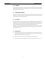
2.0 General
The Powercut 650 is a compact, completely self-contained
plasma cutting system. As shipped, the system is fully assembled and ready to cut after being connected to input
power and a source of prefiltered compressed air (90-150
psi). The Powercut 650 package uses the PT-31XLPC torch
to deliver cutting power for materials up to 5/8-in. thick or
for severing up to 3/4-in. thick.
2.1 scope
The purpose of this manual is to provide the operator with
all the information required to install and operate the Powercut 650 plasma arc cutting package. Technical reference
material is also provided to assist in troubleshooting the
cutting package.
Powercut shown with Optional Torch Wrap
and Spare Parts Kit Holder installed.
8
section 3installation
3.0General
Proper installation can contribute materially to the satisfactory and trouble-free operation of the
Powercut 650 cutting package. It is suggested that each step in this section be studied carefully
and followed as closely as possible.
3.1 Equipment Required
A source of clean, prefiltered dry air that supplies 250 cfh at 80 psig is required for the cutting
operation. The air supply should not exceed 150 psig (the maximum inlet pressure rating of the
air filter-regulator supplied with the package).
3.2 Location
Adequate ventilation is necessary to provide proper cooling of the Powercut 650 and the amount
of dirt, dust, and excessive heat to which the equipment is exposed, should be minimized. There
should be at least one foot of clearance between the Powercut 650 power source and wall or any
other obstruction to allow freedom of air movement through the power source.
Installing or placing any type of filtering device will restrict the volume of intake air, thereby
subjecting the power source internal components to overheating. The warranty is void if any
type of filter device is used.
3.3 Inspection
A.
Remove the shipping container and all packing material and inspect for evidence of concealed damage which may not have been apparent upon receipt of the Powercut 650.
Notify the carrier of any defects or damage at once.
B.
Check container for any loose parts prior to disposing of shipping materials.
C.
Check air louvers and any other openings to ensure that any obstruction is removed.
9
section 3installation
ELECTRIC SHOCK CAN KILL! Precautionary measures should be taken to provide
maximum protection against electrical
shock. Be sure that all power is off by
opening the line (wall) disconnect switch
and by unplugging the power cord to the
unit when connections are made inside of
the power source.
Be sure that the power source is properly
configured for your input power supply. DO
NOT connect a power source configured for
208/230 V to a 460 V input power supply.
Damage to the machine may occur.
3.4
Connections
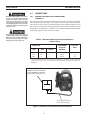
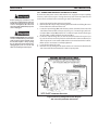
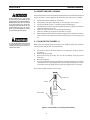
3.4.1
Primary Electrical Input Connections
(Figure 3.1)
A line (wall) disconnect switch with fuses or circuit breakers should be provided at
the main power panel (see Fig. 3-1 and Table 3-1 for fuse sizes). The input power
cable of the console may be connected directly to the disconnect switch or you
may purchase a proper plug and receptacle from a local electrical supplier. If using
plug/receptacle combination, see Table 3-1 for recommended input conductors for
connecting receptacle to line disconnect switch.
Table 3.1. Recommended Sizes for Input Conductors
and Line Fuses
Rated Input
Volts
Amp
Phases
208
35
1
230
32
1
460
8
3
Input & GND
Conductor
CU/AWG*
Fuse Size
Amps
No. 10
No. 10
No. 12
50
50
15
* Sized per National Code for 80°C rated copper conductors @ 30°C ambient. Not more than three
conductors in raceway or cable. Local codes should be followed if they specify sizes other than those
listed above.
CUSTOMER FUSED LINE DISCONNECT SWITCH (See Table
3.1 and WARNING in regards to
chassis ground in Section 3.4)
Factory supplied primary
power cable with plug.
Figure 3.1 Customer Fused Line Disconnect and Receptacle
10
section 3installation
3.4.2 Connecting Powercut 650 for 208 vac Input
Before making any connections to the
power source output terminals, make sure
that all primary input power to the power
source is deenergized (off) at the main
disconnect switch and that the input power
cable is unplugged.
ELECTRIC SHOCK CAN KILL! Precautionary
measures should be taken to provide maximum protection against electrical shock.
Be sure that all power is off by opening
the line (wall) disconnect switch and by
unplugging the power cord to the unit
when reconnecting for 208 Vac input.
The Powercut 650 power source with 208/230 vac, single phase input capability
is factory set for 230 vac input. If using 208 vac input, the Powercut 650 must be
reconnected as follows before connecting to 208 vac input power.
1. Unplug the unit from the primary input power.
2. Remove the left side panel by removing the front handle and sliding the cover
forward from the aluminum frame rail.
3. Locate the input bridge (IBR) and the two-position terminal block on the left
side of the unit towards the rear panel (see Fig. 3.2). Locate the gray wire connected to TB5-2 and to IBR terminal "R". For 208 vac input, disconnect the gray
wire from TB5-2 and then firmly connect it to TB5-1.
4. Locate the output bridge (D1) on the left side towards the front panel (see
fig. 3.2). Disconnect and swap leads X2 and X3 from the main transformer. For
208 vac input, X2 is connected to TB3 and X3 is connected to terminal 3 of D1.
Make sure the connections are firmly tightened.
5. Leave all other wires the same.
6. Reinstall cover by sliding it back into the frame rail. Connect the front handle
and connect the Powercut 650 to the 208 vac input power.
Figure 3.2 Primary Voltage Connection Diagram
208 / 230 vac Input Power Connections
11
section 3installation
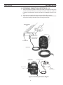
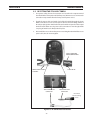
3.5 SECONDARY CONNECTIONS (Refer to Fig. 3.3)
1. The Powercut 650 is supplied from the factory with the complete PT-31XLPC torch
and the work cable with clamp assembly pre-installed. No further installation
is required. For information on torch connections or refitting the torch (see Sec.
5.4).
2. Connect your air supply to the inlet connection of the filter-regulator.
3. Clamp the work cable to the workpiece. Be sure the workpiece is connected to
an approved earth ground with a properly sized ground cable.
Grounded Work
Table
Be sure work is
in good contact
with the table
Earth Ground
Work Cable
Air Pressure
Adjustment Knob
Air Supply Connection
Moisture Bleed
Screw
Air Supply
250cfh @ 80 psig
Figure 3.3 Secondary Connections Diagram
12
section 3installation
3.6 ASSEMBLING PT-31XLPC CONSUMABLE PARTS
Make sure power switch on power source
is in OFF position and primary input power
is deenergized.
The PT-31XLPC Torch is supplied complete; ready to cut and needs no further
assembly. If it becomes necessary to inspect the front end wear parts, see Figure
3.4 for correct assembly order.
Install the electrode, baffle, nozzle, and heat shield as shown in Fig. 3.4. Tighten heat
shield snugly but do not overtighten.
BE SURE to install the swirl baffle in the
torch. Failure to do so would allow the
nozzle (tip) to contact the electrode.
This contact would permit high voltage
to be applied to the nozzle. Your contact
with the nozzle or workpiece could then
result in serious injury or death by
electric shock.
Torch Body
*20072
Electrode
20862
Nozzle
20860
Swirl Baffle
20463
The PT-31XLPC torch head contains a gas
flow check valve that acts in conjunction
with the flow switch and circuitry within
the power source. This system prevents
the torch from being energized with high
voltage if the torch switch is accidentally
closed when the shield is removed. ALWAYS REPLACETORCHWITHTHE PROPER
TORCH MANUFACTURED BY ESAB SINCE
IT ALONE CONTAINS ESAB’S PATENTED
SAFETY INTERLOCK.
*Includes the following items:
Seat - 19679
O-ring - 950790
Heat Shield
20282
NOZZLE, SWIRL BAFFLE AND ELECTRODE IN PLACE READY FOR INSTALLATION OF HEAT SHIELD.
Figure 3.4 Assembly of “XT” Consumable Parts
13
section 3installation
14
section 4operation
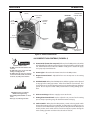
B. POWER LIGHT
(WHITE)
REAR VIEW
H. FAULT LIGHT
(AMBER)
E. AIR
PRESSURE
GAUGE
F. AIR PRESSURE
CONTROL KNOB
C. CURRENT
CONTROL
KNOB
D. AIR
TEST SWITCH
G. TRIGGER LOCK
SWITCH
A. POWER ON-OFF
(I-O) SWITCH
FRONT VIEW
Figure 4.1. Powercut 650 Controls
4.0 Powercut 650 CONTROLS (FIGURE 4.1)
ELECTRIC SHOCK can kill.
• Do NOT operate the unit with the cover
removed.
• Do NOT apply power to the unit while
holding or carrying the unit.
• Do NOT touch any torch parts forward
of the torch handle (nozzle, heat shield,
electrode, etc.) with power switch on.
A. Power Switch (located on rear panel). When placed in ON position, the white
pilot light will glow indicating control circuit is energized and the cooling fan will
run. The Powercut 650 is now in the "READY" mode given a suitable air supply
and a properly assembled torch.
B. Power Light. Indicates that the Power Switch is in the ON position.
C. Output Current Control. Adjustable from 10 to 40 amperes to suit cutting
conditions.
D. Air Check Switch. When placed in ON position, air filter-regulator can be adjusted
to 80 psig before cutting operations. Allow air to flow for a few minutes. This
should remove any condensation that may have accumulated during shutdown
period. Be sure to place switch in OFF position before starting cutting operations.
ARC RAYS can burn eyes and skin;
NOISE can damage hearing.
• Wear welding helmet with No. 6 or 7 lens
shade.
• Wear eye, ear, and body protection.
E. Air Pressure Gauge. Indicates supply pressure to the unit.
F. Air Regulator Control Knob. Used to adjust the air pressure for the cutting
process. Proper operating range for the Powercut 650 is 80 psig.
G. Lock-In Switch. When placed in ON position, permits releasing torch switch
button after cutting arc has been initiated. To extinguish arc at end of cut, press
and release torch switch button again or pull torch away from work. When placed
in OFF position, torch switch must be held closed by the operator during the
entire cutting operation and then released at the end of cut.
15
section 4operation
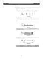
H. Fault Light. Will glow amber under the following conditions and operations
will come to a complete stop.
Flow Fault: The fault light will be mostly on but will flick off for approx.1/10th
of a second every second. This indicates that the air flow supply is low.
ON
OFF
0
1
2
Seconds
3
Over Temperature: The fault light will be mostly off but will flick on for approx.
1/10th of a second every second. This indicates that the duty cycle has been
exceeded. Allow the power source to cool down before returning to operation.
ON
OFF
0
3
1
2
Seconds
High/Low Line Voltage: The fault light will rapidly blink on and off (five times
per second). This indicates that the input voltage is outside the “+ or -” 15%
range of the input rating.
ON
OFF
0
1
2
Seconds
3
Over-Current: The fault light will be on continuously. This indicates that input
current has been exceeded.
ON
OFF
0
1
2
Seconds
3
All fault signals will remain on for a minimum of 10 seconds. If fault clears,
all will reset automatically except for over-current. To clear over-current,
the power must be shut off for 5 seconds and then turned back on.
16
section 4operation
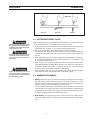
TOO FAST
TOO SLOW
CORRECT
Fig. 4.2 - Effect of Cutting Speed
4.1 CUTTING WITH THE PT-31XLPC
Wear the usual protective gloves, clothing, and helmet. Helmet with filter lens
shade No. 6 or 7 should provide adequate
protection for your eyes.
Never touch any parts forward of the
torch handle (tip, heat shield, electrode,
etc.) unless the power switch is in the
OFF position.
Position the Powercut 650 at least 10
feet (3 meters) from the cutting area to
protect the unit from sparks and hot slag
from the cutting operation.
After placing the primary (wall) switch to the ON position and making control and
air pressure adjustments as described above, proceed as follows:
1. Touch the tip of the torch to the workpiece (or within 0.020-in. of the workpiece)
holding the torch at about 15- 30° angle to avoid damaging the tip.
2. Depress the torch switch. (Air and high frequency should energize.)
3. Two seconds after depressing torch switch, the plasma arc will start cutting. (If
using the LOCK-IN mode, torch switch can be released after establishing the cutting arc.)
4. After starting the cut, the tip can be dragged along the workpiece if cutting up
to 1/4'’ thick material. When cutting material greater than 1/4'’, maintain a 1/8'’
tip-to-work (standoff ) distance.
5. When ending a cut, the torch switch should be released (press and release if
using LOCK-IN mode) and lifted off the workpiece just before the end of the cut
to minimize double-arcing which can damage the tip. This is to prevent high
frequency from reigniting after cutting arc extinguishes.
6. In the postflow mode, the arc can be restarted immediately by depressing the
torch switch. The two second preflow will automatically cancel.
4.2 OPERATING TECHNIQUES
1. Piercing - Materials (up to 1/8-in. thick) may be pierced with the torch touching
the work. When piercing thicker materials (up to 3/16-in. aluminum or 1/4-in.
stainless or carbon steel) at an angle, position the torch .020" above the workpiece.
Start the cutting arc, then immediately raise the torch to
1/16" stand-off and move the torch along the cut path. This will reduce the chance
of spatter from entering the torch and prevent the possibility of welding the tip
to the plate. The torch should be angled at about 30° when starting to pierce,
and then straightened after accomplishing the pierce.
2.Grate Cutting - For rapid restarts, such as grate or heavy mesh cutting, do not
release the torch switch. This avoids the 2 second preflow portion of the cutting
cycle.
17
section 4operation
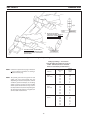
2
1
WHEN THE ARC BREAKS
THROUGH THE WORK, BRING THE
TORCH TO AN UPRIGHT POSITION AND PROCEED TO CUT.
TO START A PIERCE, TILT THE TORCH
TO PREVENT MOLTEN MATERIAL FROM
COMING BACK AGAINST AND DAMAGING THE TORCH.
Figure 4.3. Piercing Technique using the PT-31XLPC
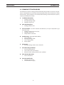
Cutting Speed Range — Powercut 650
(Using Air with XT Consumables 40 A @ 75 psi)
Nozzle - P/N 20860, Electrode - P/N 20862
With 1/16" Standoff (Tip to Work Distance)
Thickness
Material
(In.)
NOTE: Lower the air pressure to 75 psig on materials
< 1/16" or when inconsistent arc starting is
experienced at 80 psig.
NOTE: The speeds given here are typical for best
quality cuts. Your actual speeds may vary
depending on material composition, surface
condition, operator technique, etc. If cutting
speed is too fast, you may lose the cut. With
slower speeds excessive dross may accumulate. If speed is too slow, the arc may extinguish.
Air cutting typically produces a rough face on
stainless steel and aluminum.
18
Cutting
Speed
(ipm)
Carbon
Steel
(AISI 1020)
1/16
1/8
1/4
3/8
1/2
5/8
3/4
330
105
53
22
12
8
4
Stainless
Steel
(AISI 304)
1/16
1/8
1/4
3/8
1/2
5/8
3/4
320
90
40
20
12
8
3
Aluminum
(6061)
1/16
1/8
1/4
3/8
1/2
5/8
3/4
450
200
70
30
14
11
8
section 4operation
4.3 Common Cutting Problems
Listed below are common cutting problems followed by the probable cause of each. If problems are determined to be caused by the Powercut 650, refer to the maintenance section
of this manual. If the problem is not corrected after referring to the maintenance section,
contact your ESAB representative.
A.
Insufficient Penetration.
1. Cutting speed too fast.
2. Damaged cutting nozzle.
3. Improper air pressure.
B.
Main Arc Extinguishes.
1. Cutting speed too slow.
C.
Dross Formation. (In some materials and thicknesses, it may be impossible to get
dross-free cuts.)
1. Cutting speed too fast or too slow.
2. Improper air pressure.
3. Faulty nozzle or electrode.
D.
Double Arcing. (Damaged Nozzle Orifice.)
1. Low air pressure.
2. Damaged cutting nozzle.
3. Loose cutting nozzle.
4. Heavy spatter.
E.Uneven Arc.
1. Damaged cutting nozzle or worn electrode.
F.Unstable Cutting Conditions.
1. Incorrect cutting speed.
2. Loose cable or hose connections.
3. Electrode and/or cutting nozzle in poor condition.
G.
Main Arc Does Not Strike.
1. Loose connections.
H.
Poor Consumable Life.
1. Improper gas pressure.
2. Contaminated air supply.
19
section 4operation
20
section 5maintenance
5.0 Inspection and Cleaning
If this equipment does not operate
properly, stop work immediately and
investigate the cause of the malfunction.
Maintenance work must be performed
by an experienced person, and electrical work by a trained electrician. Do not
permit untrained persons to inspect,
clean, or repair this equipment. Use only
recommended replacement parts.
Frequent inspection and cleaning of the Powercut 650 is recommended for safety and
proper operation. Some suggestions for inspecting and cleaning are as follows:
A.
B.
C.
D.
E.
F.
G.
Check work cable to workpiece connection.
Check safety earth ground at workpiece and at power source chassis.
Check heat shield on torch. It should be replaced if damaged.
Check the torch electrode and cutting nozzle for wear on a daily basis. Remove
spatter or replace if necessary.
Make sure cable and hoses are not damaged or kinked.
Make sure all fittings and ground connections are tight.
With all input power disconnected, and wearing proper eye and face protection,
blow out the inside of the Powercut 650 using low-pressure dry compressed
air.
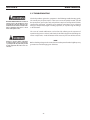
5.1 Flow Switch (Figure 5-1)
Be sure that the wall disconnect switch
or wall circuit breaker is open before attempting any inspection or work inside
of the Powercut 650.
When excessive contamination is found in the air, the flow switch (FS) should be
removed, disassembled and cleaned as follows:
A.
B.
C.
D.
E.
Ensure the system is shut down and there is no trapped air under pressure in
the piping.
Remove the piston plug.
Remove the spring (FS-4 only). Use care when handling spring to prevent
distortion.
Remove the piston.
Clean all parts with cleaning agent. Ensure cleaning agent does not contain
solvents which can degrade polysulfone. Warm water and detergent is recommended for cleaning. Allow all parts to dry thoroughly before reassembly.
Reassemble the flow switch in reverse order.
PISTON PLUG
SPRING
PISTON
FLOW SWITCH
Figure 5-1. Disassembly / Assembly of Flow Switch
21
section 5maintenance
5.2 Troubleshooting
ELECTRIC SHOCK CAN KILL! Be sure that all
primary power to the machine has been
externally disconnected. Open the line
(wall) disconnect switch or circuit breaker
before attempting inspection or work
inside of the power source.
Check the problem against the symptoms in the following troubleshooting guide.
The remedy may be quite simple. If the cause cannot be quickly located, shut off
the input power, open up the unit, and perform a simple visual inspection of all the
components and wiring. Check for secure terminal connections, loose or burned
wiring or components, bulged or leaking capacitors, or any other sign of damage
or discoloration.
The cause of control malfunctions can be found by referring to the sequence of
operations (Figures 5-2 and 5-5) and electrical schematic diagram and checking the
various components. A volt-ohmmeter will be necessary for some of these checks.
Voltages in plasma cutting equipment
are high enough to cause serious injury
or possibly death. Be particularly careful
around equipment when the covers are
removed.
NOTE
Before checking voltages in the circuit, disconnect the power from the high frequency
generator to avoid damaging your voltmeter.
22
section 5maintenance
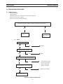
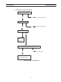
5.3 Troubleshooting Guide
A.
Difficult Starting.
• Change electrode
• Change nozzle
• Check for good, clean connection of work lead to workpiece
• Check air pressure (65 - 75 psig)
• Check torch power cable for continuity
Depress torch switch. After 2 seconds, is high frequency present?
Yes
No
Repair power
source
B.
No Air
Is air hose connected?
Yes
Repair/replace
high frequency
unit
No
Is air adjusted to 65 - 75 psig?
Yes
No
Does air come on with air check switch?
Yes
No
Check continuity of torch switch
Connect
OK
No
Adjust
• No electrode in torch
• No valve pin in torch
• Replace electrode
• Replace valve pin
Replace torch switch
Repair power source
Figure 5-2. Sequence of Operations
23
section 5maintenance
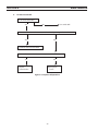
C.
Air does not shut off
Is air check switch OFF?
Yes
No
Does arc start when nozzle contacts work without depressing torch switch?
Yes
No
Check for short in torch switch
Does air flow even when Powercut 650 power switch is OFF?
Turn switch OFF
Yes
Replace
solenoid valve
No
Repair power
source
Figure 5-3. Sequence of Operations
24
section 5maintenance
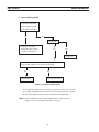
D.
White "Power" light not energized.
Is main 230 volt switch ON?
No
Turn on main disconnect
No
Insert plug in receptacle
Is plug in receptacle?
Yes
Yes
Is cooling fan turning?
Yes
No
Replace
pilot light
Check voltage at receptacle and input power line
Yes
No
Check main fuses
Faulty power
switch on Powercut 650
Figure 5-4. Sequence of Operations
25
section 5maintenance
E. Amber "FAULT" light ON.
Is the unit overheated?
("Fault" lights turns off
when Unit cools down.)
Yes
No
Is air flowing?
Duty cycle exceeded:
40% @ 40 A, 60% @ 30 A, Yes
or 100% @ 22 A output
No
See Sect 5.1
Is input voltage within ±15% of units input rating?
Yes
Adjust voltage •
No
Repair power source
Figure 5-5. Sequence of Operations
•
Fault light will energize if input voltage goes below or above ±15% of units
input rating. The light will not turn OFF even when correct voltage is restored.
Reset by placing Powercut 650 power switch OFF and then ON again.
NOTE: When in LOCK-IN mode, the FAULT light will turn on during second "trigger". This does not affect performance. Turn off.
26
section 5maintenance
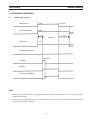
5.4 Sequence of Operation
A.
LOCK-IN "OFF" position
TORCH SWITCH
PUSHRELEASE
GAS SOLENOID VALVE
OPEN
2 SEC.
10 SEC
PREFLOW
FLOW SWITCH
CLOSE
CLOSE
Postflow
OPEN
FAULT OVERLOAD LIGHT
HF CIRCUIT
INVERTER
CUTTING ARC (CURRENT)
ENERGIZE
NOTES:
1.
When the torch switch is pushed during postflow period, the postflow and preflow times are canceled, and the HF is
energized immediately.
2.
When the amber fault pilot light comes on, cutting operation should be stopped. The postflow time starts from the
moment the torch switch is released.
27
section 5maintenance
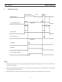
B.
LOCK-IN "ON" position
TORCH SWITCH
PUSH RELEASE
GAS SOLENOID VALVE
OPEN
PUSH
RELEASE
CLOSE
PREFLOW
2 SEC.
10 SEC
Postflow
CLOSE
FLOW SWITCH
OPEN
FAULT PILOT LIGHT
ENERGIZE
HF CIRCUIT
INVERTER
CUTTING ARC (CURRENT)
NOTES:
1.
When the torch switch is pushed during postflow period, the postflow and preflow times are canceled, and the HF is
energized immediately.
2.
When the amber fault pilot light comes on, cutting operation should be stopped. The postflow time starts from the
moment the torch switch is released.
3.
FAULT pilot light is on during second "turn-off" trigger only. This does not affect performance in any way.
28
section 5maintenance
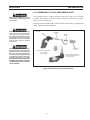
5.5Re-fitting the PT-31XLPC torch
1. For operator safety, the torch connections are located on the output terminal
board behind the lower portion of the front panel. Remove access cover to torch
connection compartment from the front panel of power source.
2. Thread the power cable and switch lead of the PT-31XLPC through the Strain
Relief on the Access Cover. Connect power cable to the torch fitting (left-hand
threads) and plug in the switch lead to the torch switch receptacle on the output
terminal board. Make sure the power cable connection is wrench-tight. Make
sure plug of switch lead is firmly locked in place.
3. Reassemble the access door to the power source. Retighten Strain Relief to secure
power cable, but do not overtighten.
ACCESS COVER FOR
TORCH CONNECTIONS
STRAIN RELIEF
WORK CLAMP & CABLE
ASSEMBLY
TORCH TRIGGER LEAD
CONNECTION
TORCH POWER CABLE
CONNECTION
PT-31XLPC
Plasma Cutting
Torch
Figure 5-6. PT-31XLPC Torch Connections
29
section 5maintenance
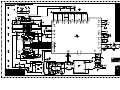
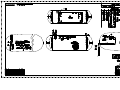
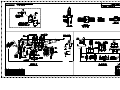
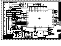
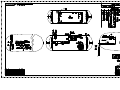
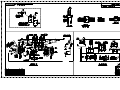
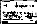
NOTE:
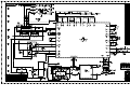
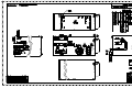
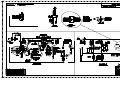
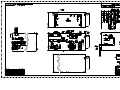
Schematics and Wiring Diagrams on 279.4mm x 431.8mm (11” x
17”) paper are included inside the back cover of this manual.
30
section 6
replacement parts
6.0Replacement Parts
6.1General
Always provide the serial number of the unit on which the parts will be used. The serial number is stamped on
the unit nameplate.
6.2
Ordering
To ensure proper operation, it is recommended that only genuine ESAB parts and products be used with this
equipment. The use of non-ESAB parts may void your warranty.
Replacement parts may be ordered from your ESAB Distributor.
Be sure to indicate any special shipping instructions when ordering replacement parts.
Refer to the Communications Guide located on the back page of this manual for a list of customer service phone
numbers.
Note
Bill of material items that have blank part numbers are provided for customer information only.
Hardware items should be available through local sources.
31
section 6
replacement parts
32
section 6
replacement parts
33
section 6
replacement parts
34
section 6
replacement parts
35
section 6
replacement parts
Q1
section 6
replacement parts
37
section 6
replacement parts
38
section 6
replacement parts
39
section 6
replacement parts
40
section 6
replacement parts
41
section 6
replacement parts
42
revision history
1. The "A" revision of 4/2003 incorporated updates of the schematic diagrams and the replacement parts section. See dneco #'s 023434 & 033078. Various formatting errors have also been corrected.
2. The revision of 7/2003 made various editorial changes to pages 15,17, 19 and 20.
3. The revision of 8/2003 updated torch wrap pictures on page 11.
4. The revision of 01/2005 converted PageMaker file to InDesign. Fonts were changed to Myriad Pro. This was done to allow translations to be done in Spanish and Portuguese. Revision letter stayed at "A" as no changes to content were made.
5. The revision of 02/2005 replaced torch body part number 35553 with 0558000790 (20072) in Section 2 and in Figure
3.4 in Section 3. Package and console information for 460V machines added along with schematic and wiring
diagram.
6. Revision "B" - 05/2005 - added Air Line Filter Regulator p/n 0558005394 note in Replacement Parts section per CN #053013. Updated format.
7. Revision "B" - 06/2005 - added ESAB Console item no. 0558003515.
In replacement parts section - Added item 1 page 32 p/n 0558005498M.
Deleted "460 only" reference on item 2 page 33.
8. Revision 08/2005 - Made various updates per D. Smith and in replacement parts section, updated finger guard from: p/n 0558002994 to: p/n 0558005659 per CN-053103.
9. Revision 12/2005 - Updated all rear view pics per D. Smith.
10. Revision 04 / 2006 - Updated entire Replacement Parts subsection per ECN #063058.
11. Revision 12/2007 - Updated Replacement Parts to revision "R" .
43
ESAB Welding & Cutting Products, Florence, SC Welding Equipment
COMMUNICATION GUIDE - CUSTOMER SERVICES
A.
CUSTOMER SERVICE QUESTIONS:
Telephone: (800)362-7080 / Fax: (800) 634-7548
Hours: 8:00 AM to 7:00 PM EST
Order Entry
Product Availability
Pricing Order Information Returns
B.
ENGINEERING SERVICE:
Telephone: (843) 664-4416 / Fax : (800) 446-5693
Hours: 7:30 AM to 5:00 PM EST
Warranty Returns Authorized Repair Stations Welding Equipment Troubleshooting
C.
TECHNICAL SERVICE:
Telephone: (800) ESAB-123/ Fax: (843) 664-4452
Part Numbers
Technical Applications
Specifications
Hours: 8:00 AM to 5:00 PM EST
Equipment Recommendations
D.
LITERATURE REQUESTS:
Telephone: (843) 664-5562 / Fax: (843) 664-5548
Hours: 7:30 AM to 4:00 PM EST
E.
WELDING EQUIPMENT REPAIRS:
Telephone: (843) 664-4487 / Fax: (843) 664-5557
Repair Estimates Repair Status
Hours: 7:30 AM to 3:30 PM EST
F.
WELDING EQUIPMENT TRAINING
Telephone: (843)664-4428 / Fax: (843) 679-5864
Training School Information and Registrations
Hours: 7:30 AM to 4:00 PM EST
G.
WELDING PROCESS ASSISTANCE:
Telephone: (800) ESAB-123 Hours: 7:30 AM to 4:00 PM EST
H.
TECHNICAL ASST. CONSUMABLES:
Telephone : (800) 933-7070
Hours: 7:30 AM to 5:00 PM EST
IF YOU DO NOT KNOW WHOM TO CALL
Telephone: (800) ESAB-123
Fax: (843) 664-4462
Hours: 7:30 AM to 5:00 PM EST
or
visit us on the web at http://www.esabna.com
The ESAB web site offers
Comprehensive Product Information
Material Safety Data Sheets
Warranty Registration
Instruction Literature Download Library
Distributor Locator
Global Company Information
Press Releases
Customer Feedback & Support
F15-696-D
12 / 2007