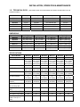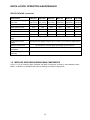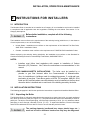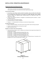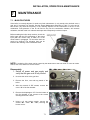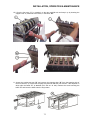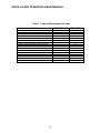
1
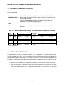
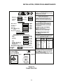
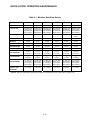
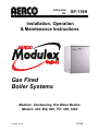
Instruction
No.
GF-115H
AERCO INTERNATIONAL, Inc., Northvale, New Jersey, 07647 USA
Installation, Operation
& Maintenance Instructions
Gas Fired
Boiler Systems
Modular, Condensing, Hot Water Boilers
Models: 303, 454, 606, 757, 909, 1060
Printed in U.S.A.
7/17/08
Telephone Support
Direct to AERCO Technical
Support
(8 to 5 pm EST, Mon. – Fri.)
1-800- 526-0288
The information contained in this manual is
subject to change without notice from AERCO
International, Inc.
AERCO makes no warranty of any kind with
respect to this material, including but not limited
to implied warranties of merchantability and
fitness for a particular application. AERCO
International is not liable for errors appearing in
AERCO International, Inc.
159 Paris Avenue
Northvale, NJ 07647-0128
www.aerco.com
© AERCO International, Inc., 2008
this manual. Nor for incidental or consequential
damages occurring in connection with the
furnishing, performance, or use of this material.
INSTALLATION, OPERATION & MAINTENANCE
TABLE OF CONTENTS
Chapter/Paragraph
1
2
3
4
Page
SAFETY SYMBOLS AND WARNINGS
iii
IMPORTANT
iii
FOR YOUR SAFETY
v
GENERAL DESCRIPTION
1-1
1.1
TECHNICAL FEATURES
1-1
1.2
CODES AND STANDARDS APPROVALS
1-2
1.3
INSTALLATION FLEXIBILITY
1-2
1.4
DIMENSIONS
1-3
1.5
TECHNICAL DATA
1-5
1.6
MODULEX SIDE VIEW SHOWING MAIN COMPONENTS
1-6
1.7
BOILER FREEZE PROTECTION
1-7
INSTRUCTIONS FOR INSTALLERS
2-1
2.1
INTRODUCTION
2-1
2.2
INSTALLATION INSTRUCTIONS
2-1
2.2.1
UNPACKING THE BOILER
2-1
2.2.2
LOCATING THE BOILER
2-3
2.2.3
2.2.4
PAD HEIGHT FOR BOILER
BOILER CONNECTIONS
2-3
2-4
2.3
BOILER DATA PLATE
2-8
GENERAL INFORMATION FOR THE VENTING SYSTEM
3-1
3.1
GAS VENT CATEGORIES
3-1
3.2
VENT PIPE CONNECTIONS
3-1
3.3
INSTALLATION & SIZING
3-1
3.4
REMOVAL OF EXISTING BOILER FROM COMMON VENTING
SYSTEM
3-2
PIPING
4-1
4.1
MAKEUP WATER QUALITY
4-1
4.2
MAXIMUM ALLOWABLE WORKING PRESSURE
4-1
4.3
BOILER LOOP DESIGN GUIDELINES
4-1
4.4
CSD-1 MANIFOLD ASSEMBLY
4-1
4.5
CONNECTING SUPPLY AND RETURN PIPING
4-1
4.6
SYSTEM FILLING AND DRAINING
4-2
4.7
NOTES ON CONDENSATE DRAIN
4-2
i
INSTALLATION, OPERATION & MAINTENANCE
TABLE OF CONTENTS - Continued
Chapter/Paragraph
4.8
5
6
GAS MAINS AND CONNECTION
4-3
ELECTRICAL
5-1
5.1
ELECTRICAL CONNECTIONS
5-1
5.2
D.H.W. STORAGE TANK
5-2
5.3
ENABLE/DISABLE
5-2
5.4
INSTALLATION OF SENSORS
5-2
BOILER OPERATION
6-1
6.1
GENERAL DESCRIPTION AND OPERATION
6-1
6.2
MODULATION THEORY
6-1
6.3
IGNITION SEQUENCE
6-2
6.4
MODES OF OPERATION
6-2
6.4.1
INDOOR/OUTDOOR RESET
6-2
6.4.2
0 TO 10 VOLT REMOTE SET-POINT
6-3
6.4.3
CONSTANT SET-POINT
6-3
6.4.4
BOILER OPERATION IN CASE OF TROUBLESHOOTING
(MANUAL MODE)
6-3
6.5
MODULEX BOILER INITIAL STARTUP
6-3
6.5.1
TOOLS & INSTRUMENTION REQUIRED FOR COMBUSTION
CALIBRATION
INSTALLATION OF SUPPLY GAS MANOMETER
6-4
6-5
6.5.4
PREPARING THE FLUE FOR USE WITH THE COMBUSTION
ANALYZER
COMBUSTION CALIBRATION
6.6
UNIT REASSEMBLY
6-8
6.5.2
6.5.3
7
Page
6-4
6-6
MAINTENANCE
7-1
7.1
MAIN FEATURES
7-1
APPENDIX A
TEMPERATURE SENSOR RESISTANCE CHART
A-1
APPENDIX B
MODULEX PARTS LIST
B-1
ii
INSTALLATION, OPERATION & MAINTENANCE
SAFETY SYMBOLS
The following defined symbols are used throughout this manual to notify the reader
of potential hazards of varying risk levels.
INDICATES AN IMMINENTLY HAZARDOUS SITUATION, WHICH IF NOT AVOIDED,
WILL RESULT IN DEATH OR SERIOUS INJURY.
INDICATES A POTENTIALLY HAZARDOUS SITUATION, WHICH
AVOIDED, COULD RESULT IN DEATH OR SERIOUS INJURY.
IF NOT
INDICATES A POTENTIAL HAZARDOUS SITUATION, WHICH IF NOT AVOIDED,
MAY RESULT IN MINOR OR MODERATE INJURY. IT MAY ALSO BE USED TO
ALERT AGAINST UNSAFE PRACTICES.
READ ALL INSTRUCTIONS BEFORE INSTALLING.
The following WARNINGS appear here and in one or more Chapters of
this manual.
•
KEEP THE UNIT AREA CLEAR AND FREE FROM ALL COMBUSTIBLE MATERIALS AND
FLAMMABLE VAPORS OR LIQUIDS.
•
NEVER USE MATCHES, CANDLES, FLAMES OR OTHER SOURCES OF IGNITION TO CHECK
FOR GAS LEAKS.
•
DO NOT ATTEMPT TO DRY FIRE THE BOILER. STARTING THE UNIT WITHOUT A FULL
WATER LEVEL CAN SERIOUSLY DAMAGE THE UNIT AND MAY RESULT IN INJURY TO
PERSONNEL OR PROPERTY DAMAGE. THIS SITUATION WILL VOID ANY WARRANTY.
•
ELECTRICAL VOLTAGES IN THIS SYSTEM MAY INCLUDE 120 AND 24 VOLTS AC. IT MUST
BE SERVICED BY TECHNICALLY COMPETENT SERVICE TECHNICIANS.
•
ELECTRICAL POWER MUST BE REMOVED PRIOR TO PERFORMING WIRE REMOVAL OR
OTHER TEST PROCEDURES THAT CAN RESULT IN ELECTRICAL SHOCK.
•
TO AVOID PERSONAL INJURY, OBSERVE THE FOLLOWING WARNINGS:
•
DISCONNECT THE AC SUPPLY BY TURNING OFF THE SERVICE SWITCH AND AC SUPPLY
CIRCUIT BREAKER
•
SHUT OFF THE GAS SUPPLY AT THE MANUAL SHUT-OFF VALVE
•
PROVIDED WITH THE UNIT
•
ALLOW THE UNIT TO COOL TO A SAFE TEMPERATURE TO PREVENT
•
SEVERE BURNS.
iii
INSTALLATION, OPERATION & MAINTENANCE
WARNINGS CONTINUED
•
This INSTRUCTION MANUAL is an integral and indispensable part of the product. It must be
given to the user by the installers and must be kept in a safe place for future reference. In the
event that the boiler is transferred or sold, the manual must accompany the equipment.
•
This boiler must be used only for the purposes for which it has been designed. Any other use
shall be considered incorrect and dangerous, thereby voiding the warranty
•
The boiler must be installed in compliance with applicable laws and standards and according to
the manufacturer’s instructions given in this manual. Incorrect installation may cause injury to
personnel and/or damage to property. The manufacturer shall not be held liable for any such injury
and/or damage.
•
Damage and/or injury caused by incorrect installation or use, or failure to observe the
manufacturer’s instructions shall relieve AERCO from any and all contractual and extra
contractual liability.
•
DO NOT obstruct the air suction to the boiler room and/or heat dissipation devices in any other
room.
•
Keep the packaging out of the reach of children as it may represent a choking and suffocation
hazard.
•
Non-observance of the above requirement may jeopardize the safety of the boilers and expose
people, animals and property to danger.
CAUTIONS appear here and in one or more Chapters of this
manual.
•
CAUTION, THE IGNITER MAY BE HOT. USE CARE TO AVOID SERIOUS BURNS
•
Caution must be observed to prevent damage to the AERCO Modulex Boiler or associated
equipment. Failure to observe precautions may also void the Boiler warranty.
•
Prior to installing the boiler, check to ensure that the technical data corresponds to
requirements for its intended use in the system.
•
Check that the boiler is intact and that it has not been damaged during transport and handling. Do
not install equipment, which is evidently damaged and/or faulty.
•
Only original accessories must be used for all boilers supplied with options or kits (including
electrical ones).
•
Dispose of the packaging with care, as all the materials can be recycled. The packaging must
therefore be sent to specific waste management sites.
•
In the event of failure and/or faulty functioning, switch off the boiler. Do not attempt to make
repairs: contact qualified technicians. Original parts must be used for all repairs to the boiler.
•
In the event of long periods of inactivity of the boiler, disconnect it from the power mains and close
the gas valve. (In this case, the boiler’s electronic anti-freeze function will not be operative.)
Should there be a risk of freezing, add anti-freeze: it is not advisable to empty the system as
this may result in damage; use specific “aluminum-friendly”, neutral pH anti-freeze products
suitable for multi-metal heating systems.
•
To guarantee efficiency and correct functioning of the equipment it is legally binding to
service the boilers once a year according to the schedule indicated in the relative
section of this manual.
iv
INSTALLATION, OPERATION & MAINTENANCE
FOR YOUR SAFETY
For boilers that use gaseous fuel, what to do if you smell gas.
•
•
•
•
Do not try to light any appliance.
Do not touch any electric switch; do not use any phone in your building.
Immediately call your gas supplier from a neighbor’s phone. Follow the
gas supplier’s instructions.
If you cannot reach your gas supplier, call the fire department.
NEVER USE FLAMES TO DETECT GAS LEAKS.
This boiler has been built for installation in the country indicated on the technical
data plate. Installation in any other country may be a source of danger for
people, animals and property.
Carefully read the warranty conditions and clauses on the warranty certificate
attached to the boiler.
IMPORTANT – FOR MASSACHUSETTS INSTALLATIONS
Boiler Installations within the Commonwealth of Massachusetts must conform to the
following requirements:
• Boiler must be installed by a plumber or a gas fitter who is licensed within the
Commonwealth of Massachusetts.
• Prior to unit operation, the complete gas train and all connections must be leak
tested using a non-corrosive soap.
• If a glycol solution is used as anti-freeze protection, a backflow preventer must
be installed upstream of the Fill/Makeup Valve.
• The vent termination must be located a minimum of 4 feet above grade level.
• If side-wall venting is used, the installation must conform to the following
requirements extracted from 248 CMR 5.08 (2):
(a) For all side wall horizontally vented gas fueled equipment installed in every dwelling, building or
structure used in whole or in part for residential purposes, including those owned or operated by the
Commonwealth and where the side wall exhaust vent termination is less than seven (7) feet above
finished grade in the area of the venting, including but not limited to decks and porches, the following
requirements shall be satisfied:
1. INSTALLATION OF CARBON MONOXIDE DETECTORS. At the time of installation of the
side wall horizontal vented gas fueled equipment, the installing plumber or gasfitter shall observe
that a hard wired carbon monoxide detector with an alarm and battery back-up is installed on the
floor level where the gas equipment is to be installed. In addition, the installing plumber or
gasfitter shall observe that a battery operated or hard wired carbon monoxide detector with an
alarm is installed on each additional level of the dwelling, building or structure served by the side
wall horizontal vented gas fueled equipment. It shall be the responsibility of the property owner to
secure the services of qualified licensed professionals for the installation of hard wired carbon
monoxide detectors
-v-
INSTALLATION, OPERATION & MAINTENANCE
Extracted Information From 248 CMR 5.08 (2) – Continued
a. In the event that the side wall horizontally vented gas fueled equipment is installed in
a crawl space or an attic, the hard wired carbon monoxide detector with alarm and
battery back-up may be installed on the next adjacent floor level.
b. In the event that the requirements of this subdivision can not be met at the time of
completion of installation, the owner shall have a period of thirty (30) days to comply with
the above requirements; provided, however, that during said thirty (30) day period, a
battery operated carbon monoxide detector with an alarm shall be installed.
2. APPROVED CARBON MONOXIDE DETECTORS. Each carbon monoxide detector as
required in accordance with the above provisions shall comply with NFPA 720 and be ANSI/UL
2034 listed and IAS certified.
3. SIGNAGE. A metal or plastic identification plate shall be permanently mounted to the exterior
of the building at a minimum height of eight (8) feet above grade directly in line with the exhaust
vent terminal for the horizontally vented gas fueled heating appliance or equipment. The sign
shall read, in print size no less than one-half (1/2) inch in size, "GAS VENT DIRECTLY BELOW.
KEEP CLEAR OF ALL OBSTRUCTIONS".
4. INSPECTION. The state or local gas inspector of the side wall horizontally vented gas fueled
equipment shall not approve the installation unless, upon inspection, the inspector observes
carbon monoxide detectors and signage installed in accordance with the provisions of 248 CMR
5.08(2)(a)1 through 4.
(b) EXEMPTIONS: The following equipment is exempt from 248 CMR 5.08(2)(a)1 through 4:
1. The equipment listed in Chapter 10 entitled "Equipment Not Required To Be Vented" in the
most current edition of NFPA 54 as adopted by the Board; and
2. Product Approved side wall horizontally vented gas fueled equipment installed in a room or
structure separate from the dwelling, building or structure used in whole or in part for residential
purposes.
(c) MANUFACTURER REQUIREMENTS - GAS EQUIPMENT VENTING SYSTEM PROVIDED. When
the manufacturer of Product Approved side wall horizontally vented gas equipment provides a venting
system design or venting system components with the equipment, the instructions provided by the
manufacturer for installation of the equipment and the venting system shall include:
1. Detailed instructions for the installation of the venting system design or the venting system
components; and
2. A complete parts list for the venting system design or venting system.
(d) MANUFACTURER REQUIREMENTS - GAS EQUIPMENT VENTING SYSTEM NOT PROVIDED.
When the manufacturer of a Product Approved side wall horizontally vented gas fueled equipment does
not provide the parts for venting the flue gases, but identifies "special venting systems", the following
requirements shall be satisfied by the manufacturer:
1. The identification of each "special venting system" shall include the listing of either the
website, phone number or manufacturer’s address where the venting system installation
instructions can be obtained; and
2. The "special venting systems" shall be Product Approved by the Board, and the instructions
provided with the system shall include a parts list and detailed installation instructions.
(e) A copy of all installation instructions for the Product Approved side wall horizontally vented gas fueled
equipment, all venting instructions, all parts lists for venting instructions, and/or all venting design
instructions shall remain with the appliance or equipment at the completion of the installation.
_________________________________[End of Extracted Information From 248 CMR 5.08 (2)]
vi
INSTALLATION, OPERATION & MAINTENANCE
1 GENERAL DESCRIPTION
IMPORTANT
Each AERCO Modulex Boiler is shipped as either a Natural Gas Only Boiler OR
a Propane Gas Only Boiler. It Is Not a Dual-Fuel Boiler. Ensure that the correct
fuel and fuel pressure are used when operating the equipment.
1.1 – TECHNICAL FEATURES
Modulex is a compact, modular, gas fired, Low NOx, condensing boiler. The boiler body, is comprised
of sections of cast aluminum/magnesium/silicon alloy. The boiler is designed to recover the sensible
and the latent heat of the combustion gases, thereby allowing it to attain a thermal efficiency of 92% as
tested by the Hydronics Institute, a Division of GAMA. These cast aluminum sections make up modules
referred to as the heat modules. Each module can deliver an output between a maximum of 152 MBH
and a minimum of 45 MBH and are composed of a pre mix combustion chamber, metallic mesh radiant
burner, modulating fan with control pressure switch, gas valve, ignition device, flame detection, NTC
sensor for local temperature control and a safety thermostat.
The heat modules are housed in a single enclosure and are connected to a single exhaust manifold.
These modules are independent of each and are sequentially staged, known as cascading, to take
advantage of higher efficiencies. Each heat module has its own printed circuit (PC) board that controls
and monitors combustion as well as the temperature of each heat module providing operational safety.
The entire boiler is controlled by a single microprocessor. This microprocessor is responsible for the
staging and modulation of the heat modules, monitoring supply and return water temperatures as well
as heating and domestic hot water (DHW) zones. Other features include:
•
The heating load is shared with as many boiler modules as possible running at a minimum
output to ensure the maximum efficiency at partial load operation.
•
Access to all testing/programming parameters of each module: operation test, operation time,
boiler freeze protection from 45°F (7°C), pump’s anti seize program.
•
Lead-lag burner operation based on burner operating hours. The boiler module with the least
burner operating hours is the first to start and the burner with the most operating hours is the
first to stop.
•
D.H.W. production by a priority sensor, with control capability of a dedicated pump or a 3-way
diverting valve for storage tank temperature control.
•
A service mode for manual operation of individual heat modules capability for troubleshooting
or combustion calibration
•
Diagnostics including relay and sensor testing.
Reliability is improved by the modular design of the Modulex since each heat module is independent of
the other, having its own ignition and combustion safeguard system. If one of the boiler’s heat modules
stops functioning, the remaining module(s) continue to operate.
The Modulex boiler can be comprised of from 2 to 7 modules and 3 to 8 cast aluminum sections. The
input to each heat module is 151.5 MBTU/Hr. The smallest Modulex 303, comprised of two heat
modules, has a combined total input of 303,000 BTU/Hr (2 x 151.5 = 303 MBTU) while the largest, the
1060 comprised of 7 heat modules has a total input of 1060 MBTU’s (See Table 1-1).
For one Modulex 303 boiler consisting of two modules, the output modulates from 15% to 100%. For a
Modulex 1060 boiler consisting of seven modules, the output modulates from 4.3% and 100%. If a
system comprised of two boilers is installed, then the modulation range for each boiler increases to 7.5%
to 100% for the Modulex 303 and 2.2% to 100% for the Modulex 1060.
1-1
INSTALLATION, OPERATION & MAINTENANCE
1.2 - CODE AND STANDARDS APPROVALS
MODULEX has been reviewed for compliance with the applicable sections of the following North
American Standards:
Z21.13:
ASME SECTION IV:
BTS 2000:
SCAQMD Rule
1146.2:
CSD-1-2004:
GAS FIRED LOW PRESSURE STEAM AND HOT WATER BOILERS
BOILER AND PRESSURE VESSEL CODE RULES FOR CONSTRUCTION
OF HEATING BOILERS
TESTING STANDARD METHOD TO DETERMINE EFFICIENCY OF
COMMERCIAL SPACE HEATING BOILERS
NOx EMISSIONS FROM WATER HEATERS AND SMALL BOILERS
CONTROLS AND SAFETY DEVICES FOR AUTOMATICALLY FIRED
BOILERS
Table 1-1. – Modulex Boiler Output Range, Turn-Down Ratio & Condensate Production
Heat
Modules
2
3
4
5
6
7
1
Output Range MBH (KW)
Model
303
454
606
757
909
1060
Min.
41(12)
41(12)
41(12)
41(12)
41(12)
41(12)
Max.
279 (82)
418 (122)
558 (163)
696 (204)
835 (245)
975 (286)
Turn Down
Ratio
6:1
10:1
13:1
16:1
20:1
23:1
Condensate Production [gph (l/h)]
Min.
1.3 (5)
Max.
3.4 (13)
1.9 (7.3)
2.7 (10.1)
3.3 (12.6)
4.0 (15.1)
4.6 (17.6)
5.3 (20)
7.1 (27)
9.0 (34)
10.6 (40)
12.4 (47)
1
MBH = 1000 Btu/hr
1.3 INSTALLATION FLEXIBILITY
The Modulex boiler allows for installation flexibility, i.e. it is suitable to be connected with the water
supply and return and the gas connections on the Right Hand (R.H.) side (standard delivery condition)
or on the Left Hand (L.H.) side. This is accomplished by reversing the gas and water manifolds utilizing
the instructions supplied with the boiler. The same is true for the vent pipe connection, which at the
installation, can be moved from the R.H. side (standard delivery condition) to the L.H. side or to the rear
of the boiler. The installation flexibility features include the following:
•
Modulex can be installed in a multiple boiler system by the combination of two or more boilers.
•
Gas connecting pipes, supply/return water pipes can be arranged for any connection (by either
the left or right hand side of the unit, the unit is shipped with all connections on the right hand
side as viewed from the front of the unit).
•
Vent pipe, adjustable on the right, the left and behind the heating system.
1-2
INSTALLATION, OPERATION & MAINTENANCE
1.4 DIMENSIONS AND WEIGHTS
The dimensions and weights for each Modulex Model are shown in sheets 1 and 2 of Figure 1-1.
Figure 1-1. Modulex Dimensions and Weights (Sheet 1 of 2)
1-3
INSTALLATION, OPERATION & MAINTENANCE
Figure 1-1. Modulex Dimensions and Weights (Sheet 2 of 2)
1-4
INSTALLATION, OPERATION & MAINTENANCE
1.5 - TECHNICAL DATA
(THE NAME PLATE IS PLACED UNDER THE FRONT JACKET NEXT TO THE
CONTROL PANEL.)
Model Number
Min Input
Max Input
Max Output*
Net IBR Rating
MLX-303
MLX-454
45,500
45,500
303,000
454,000
260,000-279,000
390,000-418,000
237,000
355,000
MLX-606
45,500
606,000
521,000-558,000
474,000
MLX-757
45,500
757,000
651,000-696,000
592,000
MLX-909
45,500
909,000
781,000-835,000
710,000
MLX-1060
45,500
1,060,000
912,000-975,000
829,000
DIMENSIONS:
Model Number
Height
Width
Depth
Dry Weight
MLX-303
MLX-454
42” (1067 mm)
42” (1067 mm)
28” (711 mm)
28” (711 mm
27” (686 mm)
27” (686 mm)
405 lbs. (183.7 kg)
484 lbs. (219.6 kg)
MLX-606
42” (1067 mm)
33” (838 mm)
27” (686 mm)
575 lbs. (260.8 kg)
MLX-757
42” (1067 mm)
38” (965 mm)
27” (686 mm)
673 lbs. (305.2 kg)
MLX-909
42” (1067 mm)
44” (112 mm)
27” (686 mm)
765 lbs. (346.8 kg)
MLX-1060
42” (1067 mm)
49” (1245 mm)
27” (686 mm)
869 lbs. (394.0 kg)
SPECIFICATIONS:
Model Number
Boiler Category
Type of Gas
Gas Connections (NPT)
Max. Gas Pressure
Optimal Gas Pressure
MLX-303
MLX-454
MLX-606
MLX-757
MLX-909
MLX-1060
IV
IV
IV
IV
IV
IV
Natural Gas Natural Gas Natural Gas Natural Gas Natural Gas
Natural Gas
(MLX-303H) (MLX-454H) (MLX-606H) (MLX-757HB) (MLX-909H) (MLX-1060H)
or Propane
or Propane
or Propane
or Propane
or Propane
or Propane
(MLX-303HP) (MLX-454HP) (MLX-606HP) (MLX-757HP) (MLX-909HP) (MLX-1060HP)
1.5”
1.5”
1.5”
1.5”
1.5”
1.5”
14” W.C.
14” W.C.
14” W.C.
14” W.C.
14” W.C.
(34.8 mbar) (34.8 mbar) (34.8 mbar) (34.8 mbar) (34.8 mbar)
7” W.C.
7” W.C.
7” W.C.
7” W.C.
7” W.C.
14” W.C.
(34.8 mbar)
7” W.C.
(17.4 mbar) (17.4 mbar) (17.4 mbar) (17.4 mbar) (17.4 mbar)
(17.4 mbar)
Min. Gas Pressure
4”
(10 mbar)
4”
(10 mbar)
4”
(10 mbar)
4”
(10 mbar)
4”
(10 mbar)
4”
(10 mbar)
Max. Allowed Working
Pressure
92 psi
(634 kPa)
92 psi
(634 kPa)
92 psi
(634 kPa)
92 psi
(634 kPa)
92 psi
(634 kPa)
92 psi
(634 kPa)
1.2 FLA
1.8 FLA
2.4 FLA
3.0 FLA
3.6 FLA
4.2 FLA
2-1/2”
2-1/2”
2-1/2”
2-1/2”
2-1/2”
2-1/2”
Min. Water Flow (GPM)
11
17
22
28
38
39
Max. Water Flow (GPM)
28
42
55
70
84
98
10.5
10.6
11.6
12.6
13.7
16.1
Electrical Req:
120V 15 Amp. Max.
Water Connections
(NPT)
Water Pressure Drop
@ Max. Flow (Ft. of
Head)
1-5
INSTALLATION, OPERATION & MAINTENANCE
SPECIFICATIONS: (continued)
Model Number
MLX-303
MLX-454
MLX-606
MLX-757
MLX-909
Water Pressure Drop @
Max. Flow
5 psi
(34.5 kPa)
6 psi
(41.4 kPa)
9 psi
(62.1 kPa)
10 psi
(68.9 kPa)
13 psi
15 psi
(89.6 kPa) (103.4 kPa)
Water Volume: Gallons
2.8
3.8
4.9
5.9
6.9
8.0
Water Volume: Liters
10.4
14.4
18.4
22.3
26.3
30.2
Thermal Modules
2
3
4
5
6
7
Turn-Down Ratio
6:1
10:1
13:1
16:1
20:1
23:1
Vent Size
Vent Materials (per local
code)
Temperature Control
Range
Maximum Noise Level
NOx Emissions
Certification
Standard Listings &
Approvals
MLX-1060
4” (102 mm) 4” (102 mm) 4” (102 mm) 6” (152mm) 6” (152mm) 6” (152mm)
Can support PVC, ABS, CPVC, or AL29-4C venting materials.
All units can be applied to deliver 50°F to 185°F (10°C to 85°C) supply water.
All units deliver <50 dBA when operating at or below full fire.
All units have been certified by SCAQMD and TCEQ for <30 ppm NOx.
All units have been certified by CSA.
1.6 MODULEX SIDE VIEW SHOWING MAIN COMPONENTS
Figure 1-2 on the following page illustrates the Main Components included in each Modulex Boiler
Model. In addition, an exploded view parts list drawing is included in Appendix B.
1-6
INSTALLATION, OPERATION & MAINTENANCE
FAN
GAS VALVE
AIR INTAKE
CONNECTION
GAS PIPE
AUTOMATIC
AIR VENT
BURNER
COVER
IGNITION
FLAME
DETECTOR
LOCAL NTC
SENSOR
GLOBAL FLOW
NTC TEMPERATURE
SENSOR
H.L.
THERMOSTAT
BURNER
HOT WATER
OUTLET (SUPPLY)
ALUMINUM/
SILICON HEAT
EXCHANGER
1/4" CONNECTION
WITH PLUG
GLOBAL RETURN
NTC TEMPERATURE
SENSOR
BOILER
FRAME
COLD WATER INLET
(RETURN)
WATER DRAIN
VALVE
CONDENSATE
DRAIN TRAP
CONDENSATE
COLLECTION
TRAY MANIFOLD
FILLING-UP
ELBOW
5.9" [150 mm]
4"
[100 mm]
1" [25 mm]
Figure 1-2.
Modulex Main Components
1.7 BOILER FREEZE PROTECTION
Should the boiler water outlet temperature decrease to less than 44.6°F (7°C), the system pump will start.
Should temperature decrease to less than 37.4°F (3°C), all heat modules will start at minimum output until
the return temperature reaches 50°F (10°C). Such a protection device is exclusively for the boiler. For the
protection of the whole system, a second freeze protection thermostat is necessary to switch on the
heating system pump.
NOTE
If glycol is used as antifreeze in the boiler, a back flow preventer must be installed in the
make-up/fill line.
1-7
INSTALLATION, OPERATION & MAINTENANCE
2 INSTRUCTIONS FOR INSTALLERS
2.1 INTRODUCTION
The Modulex Boiler is intended to be installed as a Category IV vent installation and must be installed
in compliance with all applicable laws and regulations including the ones below. See section 3.1 for
Category descriptions.
Before boiler installation, complete all of the following
instructions:
The installation must conform to the requirements of the authority having jurisdiction or, in the absence
of such requirements, to one of the following:
•
United States - Installation must conform to the requirements of the National Fuel Gas Code,
ANSI Z223.1 Installation Codes.
•
Canada - Installation must conform to the requirements of CAN/CGA B149 Installation Codes.
Where required by the authority having jurisdiction, the installation must conform to the Standard for
Controls and Safety Devices for Automatically Fired Boilers, ANSI/ASME CSD-1.
NOTES:
•
Installers must follow local regulations with respect to installation of Carbon
Monoxide (CO) Detectors. Also, follow the maintenance recommendations in this
manual.
• FOR MASSACHUSETTS INSTALLATIONS: The boiler must be installed by a
plumber or gas fitter licensed within the Commonwealth of Massachusetts.
Also, for installations in buildings used for residential purposes, if a side-wall vent
termination is less than 7 feet above grade, an NFPA 720 compliant, ANSI/UL 2034
listed and IAS certified carbon monoxide detector must be installed on the floor level
where the boiler is installed and on each level of the building served by the boiler.
2.2 INSTALLATION INSTRUCTIONS
The following paragraphs in this Section provide the instructions to unpack and install the Modulex Boiler.
2.2.1 Unpacking the Boiler
The Modulex Boiler is delivered assembled and protected by a plastic bag inside a rugged cardboard
box, which is fixed on a pallet (see Figure 2-1). The pallet allows the boiler to be handled by a forklift or
pallet jack. The boiler, with the packaging, can fit through a doorway of 32 in. (81 cm), whereas, without
packaging, it can fit through a doorway of 28 in. (71 cm). To unpack the Modulex, remove both straps
and then the cardboard box from above. Check to ensure that the product is intact.
The packing elements (cardboard box, straps, plastic bags, etc…)
must not be left in children’s hands since they may be dangerous.
2-1
INSTALLATION, OPERATION & MAINTENANCE
Packed inside the boiler packing you will find:
• Painted steel panels:
• The front one connected to the back panel by a shrink wrap film
• The right hand side panel connected to the left hand panel by shrink wrap
On the front of the boiler:
•
Flue collector, with exhaust connector screwed to the pallet: 6 inch for models 303 to 606 and 8
inch for models 757 to 1060. Use these items only when the specified flue pipe size is increased
to 6” (for models 303 to 606) and 8” (for models 757 to 1060). Otherwise, use the exhaust
connector “shipped in the separate carton” described below (4” for models 303 to 606, 6” for
models 757 to 1060).
•
A plastic bag containing 3 gaskets (1 rectangular for condensate tray and flue collector, 1 square
for exhaust connector.
•
Three (3) surface-mount strap-on sensors.
•
Screws necessary for accessory installation.
•
Piping for 1 ½” condensate drain, including one tee and two 90 degree elbows.
On the back of the boiler:
•
Plastic condensate drainpipe, 38.5 inches (1meter) long, placed under the casing rear panel.
•
Outside air sensor with 49 feet, 2.5 inches (15 m) cable.
•
Manual Gas Shutoff Valve.
Shipped in a separate carton are the following:
•
Accessory kit that includes a CSD-1 installation kit for Models 303 through 606 and Models 754
through 1060 as follows:
Kit P/N 29073:
Kit P/N 29074:
Kit P/N 29075:
Kit P/N 29076:
For
For
For
For
Models
Models
Models
Models
303-606 with 50 psig Relief Valve
707-1060 with 50 psig Relief Valve
303-606 with 90 psig Relief Valve
707-1060 with 90 psig Relief Valve
See the packing list shipped in this manual package for a complete listing of accessories. See
paragraph 4.4 for more information about the CSD 1- kits.
Figure 2-1.
Packaged Modulex Boiler
2-2
INSTALLATION, OPERATION & MAINTENANCE
2.2.2 Locating the Boiler
The boiler should be located on a level, solid area or base as near to the outside wall as possible and
centrally located to the space heating distribution system. Special attention must be given to local regulations
and codes about boiler rooms and particularly to the maintaining of minimum clearances and empty space
around the boiler. The installation must be in compliance with all recent regulations and laws about boiler
rooms, installations of heating and hot water systems, ventilation, boiler venting systems capable of
evacuating the flue gases of condensing boilers and any other applicable requirement.
The minimum clearance dimensions for service access, required by AERCO, are listed below (Figure 2-2)
and on the boiler Data Plate shown in Figure 2-7. Local building codes may require more clearance and
take precedence.
Minimum clearances required:
Sides
24" (510 mm)
Front
24" (510 mm)
Rear
24" (510 mm)
Top
24" (510 mm)
Figure 2-2
Boiler Clearances (Top View)
NOTE: All gas piping, water piping and electrical conduit or cable must be arranged so that
they do not interfere with the removal of any cover, or inhibit service or maintenance of the
unit.
The boiler MUST NOT be installed on carpeting
2.2.3 Pad Height for Boiler
To properly drain and service the boiler’s condensate system, attention must be given to installation
requirements regarding the mounting height of the boiler as well as installation clearances for the removal
of the condensate collector baffle.
The boiler should be mounted on a flat and sufficiently strong base with the same dimensions as the boiler
(see Figure 1-1) and at least 4 inches (100mm) high (see Figure 4-1 in paragraph 4.7), to allow for
assembly of the condensate drain trap. An alternative to this base may be a 4 inch (100mm) deep well next
to the boiler to house the condensate siphon.
The condensate collector baffle (see Section 7) can be fixed, from the Right Hand (R.H) or Left Hand (L.H.)
side of the condensate tray. If no modification has been made, the boiler must have its R.H. side
accessible, with the vent connection fitted on the R.H or L.H. side. However, if the flue collector terminal,
with the exhaust connector, is left to of the R.H. side and if, from this same side, the baffle has to be
removed, and then the exhaust connector must have the possibility to be also removed. If it is preferred,
the baffle can be moved in order to have its mounting screw on the opposite side, regardless the position of
the flue collector chamber terminal.
2-3
INSTALLATION, OPERATION & MAINTENANCE
2.2.4 Boiler Connections
Upon delivery, the Modulex Boiler has all the connections on its R.H. side (Figure
2-3). Note that the R.H. orientation is the right hand side when viewed facing the front of the boiler. These
connections include: water supply and return, gas, combustion air intake and flue collector outlet. The
locations of the air intake and/or the flue collector outlet can be changed on site by removing knock-outs on
the boiler right, left or back side panels. To attach the exhaust connector to the flue collector, use the
screws and the gaskets supplied inside the plastic bag and use a cross-tip (Phillips) screwdriver at least 12
in. (300 mm) long.
Figure 2-3.
Boiler Connections
Water supply and return and gas connections can also be moved to the boiler’s L.H. side by inverting the
flow (supply)/return manifold on the left side using the following procedure:
1. Remove the front, side and rear panels from the boiler.
2. For reversal of the water flow (supply) and return manifolds from the R.H. to the L.H. side, remove
the small plates securing the flow (supply) and return global temperature sensors (Figure 2-4).
2-4
INSTALLATION, OPERATION & MAINTENANCE
BCM TEMP
SENSOR
AUTOMATIC
AIR VENT
E8 TEMP
SENSOR
RETURN
TEMP
SENSOR
BOILER
DRAIN
THERMOWELL
THERMOWELL
CLIP
SENSOR
BRACKET
SENSOR
CONNECTOR
BRACKET
SCREW
E8 TEMP
SENSOR
TEMPERATURE
SENSOR
E8 SENSOR
BCM & BOILER RETURN SENSORS
Figure 2-4
Right Hand (R.H.) Connection
2-5
INSTALLATION, OPERATION & MAINTENANCE
3. Disassemble the flow (supply) and return manifolds (Figure 2-5), leaving the rubber gaskets in place
on the upper holes of the aluminum sections and the rubber gaskets/diaphragms in place on the
lower holes. The diaphragms on the end sections have a hole diameter of .866 in. (22 mm).
4. Reassemble the manifolds with the threaded connection on the opposite side as shown in Figure
2-5. Change the position of the drain cock and the automatic air vent (Figure 2-6).
5. Reposition the temperature sensor white and red leads onto the new flow (supply) manifold and the
temperature sensor white and green leads onto the new return manifold.
FRONT VIEW – L.H.
FRONT VIEW – R.H.
GAS CONNECTIONS ON L.H. SIDE
(AFTER MODIFICATION CONDITION)
GAS CONNECTIONS ON R.H. SIDE
(STD. DELIVERY CONDITION)
A
C
B
B
A
C
REAR VIEW
REAR VIEW
C.H. FLOW AND RETURN
R.H. SIDE CONNECTIONS
(STD DELIVERY CONDITION).
C.H. FLOW AND RETURN
L.H. SIDE CONNECTIONS
(AFTER MODIFICATION CONDITION).
0.866" [22 mm]
0.866" (22 mm) = DIAPHRAGM FOR THE TWO
COLLECTORS POSITIONED AT THE EXTREME
ENDS
Figure 2-5
R.H. and L.H. Manifold Connection
2-6
INSTALLATION, OPERATION & MAINTENANCE
AUTOMATIC
AIR VENT
BCM TEMP
SENSOR
E8 TEMP
SENSOR
RETURN
TEMP
SENSOR
BOILER
DRAIN
THERMOWELL
THERMOWELL
CLIP
SENSOR
BRACKET
SENSOR
CONNECTOR
BRACKET
SCREW
E8 TEMP
SENSOR
TEMPERATURE
SENSOR
E8 SENSOR
BCM & BOILER RETURN SENSORS
Figure 2-6
Left Hand (L.H.) Connection
2-7
INSTALLATION, OPERATION & MAINTENANCE
6. For the gas connection, it is possible to keep the gas manifold inlet on the R.H. side, if desired, or it
can be rotated 180° to have it on the L.H. side. In case of reversal from R.H. side to L.H. side of the
gas manifold, only on the Modulex Model 303 will it be necessary to reverse plug C with the gas
valve fitting A (see gas manifold connections in Figure 2-5).
The boiler and its individual shutoff valve must be disconnected from the gas supply piping system during
any pressure testing of that system at test pressures in excess of 0.5 psi (14” W.C., 3.5 kPa).
The boiler must be isolated from the gas supply piping system by closing its individual manual shutoff valve
during any pressure testing of the gas supply piping system at test pressures equal to or less than 0.5 psi
(3.5 kPa).
The boiler shall be installed such that the gas ignition system components are protected from water
(dripping, spraying, rain, etc.) during appliance operation and service (circulator replacement, condensate
trap, control replacement etc.).
Before operating the boiler, the complete gas train and all connections must be leak tested using a noncorrosive soap solution.
2.3 DATA PLATE
A sample Data Plate for a Modulex Boiler is shown in Figure 2-7. The data in Table 2-1 following this
Figure indicates the required entries for each Modulex Model.
2-8
INSTALLATION, OPERATION & MAINTENANCE
Figure 2-7
Sample Data Plate
2-9
INSTALLATION, OPERATION & MAINTENANCE
Table 2-1. Modulex Data Plate Entries
MODEL NUMBER
REVISION
TYPE OF GAS
*SERIAL NO.
MLX-303
MLX-454
MLX-606
MLX-757
MLX-909
MLX-1060
A
A
A
A
A
A
NATURAL GAS NATURAL GAS NATURAL GAS NATURAL GAS NATURAL GAS NATURAL GAS
(MLX-1060H
(MLX-909H)
(MLX-757H)
(MLX-606H)
(MLX-454H)
(MLX-303H)
OR PROPANE OR PROPANE OR PROPANE OR PROPANE OR PROPANE OR PROPANE
(MLX-1060HP)
(MLX-909HP)
(MLX-757HP)
(MLX-606HP)
(MLX-454HP)
(MLX-303HP)
303-XX-XXXX
454-XX-XXX
606-XX-XXXX
757-XX-XXXX
909-XX-XXXX
1060-XXXXXX
MAX INPUT
303,000
454,000
606,000
757,000
909,000
1,060,000
MIN INPUT
45,000
45,000
45,000
45,000
45,000
45,000
OUTPUT
279,000
418,000
558,000
696,000
835,000
975,000
NET IBR RATING
237,000
355,000
474,000
592,000
710,000
829,000
IV
IV
IV
IV
IV
IV
14” W.C
(34.8 mbar).
14” W.C
(34.8 mbar).
14” W.C
(34.8 mbar).
14” W.C
(34.8 mbar).
14” W.C
(34.8 mbar).
14” W.C
(34.8 mbar).
4”
(10 mbar)
4”
(10 mbar)
4”
(10 mbar)
4”
(10 mbar)
4”
(10 mbar)
4”
(10 mbar)
3.2” Nat. Gas
(MLX-303H)
2.5” Propane
(MLX-303HP)
3.2” Nat. Gas
(MLX-454H)
2.5” Propane
(MLX-454HP)
3.2” Nat. Gas
(MLX-606H)
2.5” Propane
(MLX-606HP)
3.2” Nat. Gas
(MLX-757H)
2.5” Propane
(MLX-757HP)
3.2” Nat. Gas
(MLX-909H)
2.5” Propane
(MLX-909HP)
3.2” Nat. Gas
(MLX-1060H)
2.5” Propane
(MLX-1060HP)
7.0”
(17.4 mbar)
7.0”
(17.4 mbar)
7.0”
(17.4 mbar)
7.0”
(17.4 mbar)
7.0”
(17.4 mbar)
7.0”
(17.4 mbar)
BOILER CATEGORY
MAX INLET (SUPPLY)
GAS PRESSURE
MIN INLET (SUPPLY)
GAS PRESSURE
*NORMAL MANIFOLD
GAS PRESSURE
OPTIMAL INLET
(SUPPLY) GAS
PRESSURE
* NOTE: Normal manifold gas pressure measured at downstream port of gas valve ((Figure 6-2).
2-10
INSTALLATION, OPERATION & MAINTENANCE
3
GENERAL INFORMATION FOR VENTING
Note: See Venting Guide GF-115-V for venting specifications and materials.
3.1 VENT PIPE CONNECTION
The Modulex boiler is approved for a Category IV vent configuration as well as
for sealed combustion installations. Provisions for combustion and ventilation
air in accordance with section 5.3, Air for Combustion and Ventilation, of the
National Fuel Gas code, ANSI Z223.1, or Sections 7.2, 7.3, or 7.4 of CAN/CGA B149, Installation
codes, or applicable provisions of the local building codes.
Maintain clearances from combustible construction for boiler, vent connector,
and steam and hot-water pipes.
3.2 GAS VENT CATEGORIES
Federal Codes have categorized gas appliances by the vented flue gas pressure and temperature.
These categories are defined as follows:
•
Category I, being a gas appliance that operates with a non-positive vent (or natural drafted
vent) connector with a flue gas pressure and temperature at least 140°F (60°C) above its dew
point.
•
Category II, being a gas appliance that operates with a non-positive vent (or natural drafted
vent) connector with a flue gas pressure and temperature less than 140 degrees F (60 degrees
C) above its dew point.
•
Category III, being a gas appliance that operates with a positive vent (fan forced vent)
connector with a flue gas pressure and temperature at least 140 degrees F (60 degrees C)
above its dew point.
•
Category IV, being a gas appliance that operates with a positive vent (fan forced vent)
connector with a flue gas pressure and temperature less than 140 degrees F (60 degrees C)
above its dew point.
•
Direct Vent, a gas appliance is constructed and installed so that all air for combustion is
derived directly from the outdoors and all flue gases are discharged to the outdoors.
3.3 INSTALLATION AND SIZING
The AERCO Venting Guide, GF-115-V, must be consulted before any flue gas vent or air inlet piping is
designed or installed. Certified venting materials specified in GF-115-V must be used for safety and
code compliance. Because the Modulex boiler is capable of discharging low temperature exhaust
gases, the flue must be pitched back to the unit a minimum of ¼” per foot to avoid any condensate
pooling and to allow for proper drainage.
For side wall venting in Massachusetts:
•
The vent termination must be located at a minimum of 4 feet above grade level.
•
IMPORTANT: See pages v and vi of this manual (GF-115H) for detailed information pertaining
to side wall venting within the Commonwealth of Massachusetts.
3-1
INSTALLATION, OPERATION & MAINTENANCE
Pipe lengths and fittings must be calculated as part of the equivalent length. The pressure drop of the
vent and combustion air systems must not exceed 100 equivalent feet each. Note that this DOES NOT
mean the allowed combined pressure drop between the vent and combustion air is 200 equivalent feet.
That is, the vent cannot go above 100 equivalent feet, even if the combustion air is less than 100
equivalent feet, and vice versa. (See GF-115-V for detailed sizing guidelines.)
The combustion air must be free of chlorine, halogenated hydrocarbons, or other chemicals that can
become hazardous when used in gas-fired equipment. Common sources of these compounds are
swimming pools, degreasing compounds, plastic processing compounds and refrigerants. Whenever
the environment contains these types of chemicals, combustion air must be supplied from a clean area
outdoors for the protection and longevity of the equipment.
The Modulex is CSA listed for 100% sealed combustion or can be installed using room air as long as
there is an adequate supply. (See GF-115-V for detailed sizing guidelines.)
3.4 REMOVAL OF EXISTING BOILER FROM COMMON VENTING SYSTEM
At the time of removal of an existing boiler, the following steps shall be followed with each appliance
remaining connected to the common venting system placed in operation, while the other appliances
remaining connected to the common venting system are not in operation.
1. Seal any unused openings in the common venting system.
2. Visually inspect the venting system for proper size and horizontal pitch and determine there are
no blockages or restrictions, leakage, corrosion and other deficiencies that could cause an
unsafe condition.
3. When practical, close all building doors and windows as well as all doors between the space in
which the appliances remaining connected to the common venting system are located and
other spaces of the building. Turn on any appliances not connected to the common venting
system, such as clothes dryers. Turn on any exhaust fans, such as range hoods and bathroom
exhausts, so they will operate at maximum speed. Do not operate a summer exhaust fan.
Close fireplace dampers.
4. Turn on the appliance being inspected. Follow the lighting instructions. Adjust thermostat so
appliance will operate continuously.
5. Test for spillage at the draft hood relief opening after 5 minutes of main burner operation. Use
the flame of a match or candle, or smoke from a cigarette, cigar or pipe.
6. After it has been determined that each appliance remaining connected to the common venting
system properly vents when tested as outlined above, return doors, windows, exhaust fans,
fireplace dampers and any other gas-burning appliance to their previous state of use.
7. Any improper operation of the common venting system should be corrected so the installation
conforms to the National Fuel Gas code, ANSI Z223.1 and/or CAN/CGA B149, Installation
Codes. When resizing any portion of the common venting system, the common venting system
should be resized to approach the minimum size as determined using the appropriate tables in
Part 11 of the National Fuel Gas Code, ANSI Z223.1 and/or CAN/CGA B149, Installation
Codes.
3-2
4
PIPING
NOTE: For in depth piping information for the boiler, see Piping Guide
GF-115-P-H
4.1 MAKEUP WATER QUALITY
Water at the installation should be checked, monitored, maintained and treated as described in
GF-115-P-H.
NOTE: Failure of the boiler due to water quality is not covered under warranty.
4.2 - MAXIMUM ALLOWABLE WORKING PRESSURE
The Modulex boiler has a maximum allowable working pressure of 92 psi
(634kPa, 6.34 bar), and a minimum of 15 psi (103 kPa, 1 bar).
4.3 BOILER LOOP DESIGN GUIDELINES
For proper and safe operation of the water tube Modulex boiler, the primary (boiler) loop piping and the
associated fittings and accessories must be designed/selected as discussed in the following sections
4.4 CSD-1 MANIFOLD ASSEMBLY (SUPPLIED)
The installation of a low water cutoff, manual reset high limit aquastat and an ASME compliant safety
pressure relief valve designed for the boiler output capacity are required. These major components
along with a manifold and several others are supplied with the boiler and must be assembled and wired
when installing the boiler at the site. The manifold assembly components supplied are:
•
3/4” Pressure Relief Valve
•
Manifold Assembly [2-1/2” x 16” long (64 mm x 406 mm)]
•
2-1/2” NPT Union
•
Low Water Cut-Off Switch
•
Aquastat
•
Pressure/Temperature Gauge
4.5 CONNECTING SUPPLY AND RETURN PIPING (PER ANSI Z21.13A)
•
The boiler, when used in connection with a refrigeration system, must be installed so the chilled
medium is piped in parallel with the boiler with appropriate valves to prevent the chilled medium
from entering the boiler.
•
The boiler piping system of a hot water boiler connected to heating coils located in air handling
units where they may be exposed to refrigerated air circulation must be equipped with flow
control valves or other automatic means to prevent gravity circulation of boiler water during the
cooling cycle.
•
A hot water boiler installed above radiation level or as required by Authority having jurisdiction,
must be provided with a low water cutoff device either as a part of the boiler or at the time of the
installation.
4-1
INSTALLATION, OPERATION & MAINTENANCE
4.6 SYSTEM FILLING & DRAINING
•
For filling-up the system a filling tap has to be inserted on the system return pipe.
•
The filling-up can also be made through the draining tap on the boiler return manifold.
•
In both cases, an approved hydraulic disconnection system has to be fitted.
•
Before connecting the boiler, carefully rinse out the whole system with running water.
4.7 NOTES ON CONDENSATE DRAIN
To maintain proper flow of condensate the drain pipe must slope toward the drain of at least 3/8 in./ft.
(30 mm/m). The liquid column inside the condensate siphon needs to be filled with water after
installation. Its minimum height when all the fans are in operation must be at least 1 in. (25 mm). See
Figure 4-1. In order to help avoid ice from forming, the condensate piping system must be well
insulated.
DO NOT INSTALL THE CONDENSATE DRAIN WHERE FREEZING MAY
OCCUR.
Consult local codes with regard to condensate neutralization. Neutralization can be obtained by mixing
it with the buildings drain water or with limestone, which normally have a base pH.
Figure 4-1
Typical Condensate Drain Installation
4.8 GAS MAINS AND CONNECTIONS
•
Connect gas service meter to control assembly in accordance with the current version of the
ANSI Z223.1 and the local codes or utility.
•
Prior to operation, the complete gas train must be leak tested using a non-corrosive soap.
•
For gas pipe sizing and additional details, see GF-115-P-H.
4-2
INSTALLATION, OPERATION & MAINTENANCE
5
ELECTRICAL
NOTE: For additional electrical information, see Electrical Power Guide
GF-115-E
5.1 ELECTRICAL CONNECTIONS
A complete electrical wiring diagram for the Modulex is provided under separate cover in the manual
package. For electrical ratings, refer to the technical data in paragraph 1.5. The boiler installation
requires a 120 VAC, 60 Hz – single-phase power input. The electrical connections must conform to
local and NEC or CEC requirements. Utilization of adapters, multiple sockets or extensions cords are
not permitted. It is imperative that these safety requirements be adhered to. If in doubt, request an
accurate assessment of your electric system by highly qualified personnel.
AERCO is not liable for any damage caused by connection to an improper grounding system. The gas
and water feeding pipes and the central heating system pipes cannot be used as grounding means.
Boiler electric safety is guaranteed only when it is properly connected to an effective grounding system,
which is in compliance with the regulations in force.
The use of any electrically powered equipment implies the observance of some fundamental rules, such
as:
• Do not touch the boiler with any wet part of your body and/or barefooted; do not pull the
supply cable.
•
Do not expose the boiler to sunlight, rain, etc.
•
Keep the boiler away from untrained people.
WARNING
The boiler’s electrical supplying cable must not be replaced by the user. In case of any
damage to the cable, stop the boiler and contact qualified personnel for its replacement.
IMPORTANT
Prior to connecting external AC power to the Modulex boiler, the CSD-1 Supply Manifold
must be installed using the procedures described Piping Manual GF-115-P-H.
1. External power at 120 VAC, 60 Hz, single phase is first connected to the Low Water Cutoff and
Aquastat provided on the CSD-1 Supply Manifold. Refer to Wiring Diagram 68004 provided in
the manual package for connections to the CSD-1 Manifold.
2. Following connection of 120 VAC power to the CSD-1 Manifold, the power leads are routed to
the Junction Box shown in Figure 5-1. The Junction Box is accessed by removing the front
panel from the boiler.
3. Route the wires from the CSD-1 Manifold through the cutout labeled 120V on the Left side of
the boiler. If necessary, the cutout labeled 24V is used for low voltage signals such as external
sensors.
4. The boiler’s Junction Box contains a polarized terminal block. Therefore, the Red (Line - L1) and
White (Neutral - L2) wires from the CSD-1 Manifold MUST BE connected to terminals L1 and
L2 respectively on the terminal block in the Junction Box. The output cable from the Junction
Box is terminated with a 3-pole plug, which connects to the boiler’s electrical components. If
incorrectly wired, the boiler goes into a “lockout” condition.
5-1
INSTALLATION, OPERATION & MAINTENANCE
5.
It is necessary to install a double-pole switch on the supply line in an easily accessible position in
order to quickly and safely disconnect service. Do Not affix switch to boiler sheet metal
enclosure.
Figure 5-1. Junction Box Wiring Connections
After placing the boiler in operation, the ignition system safety shutoff device must be tested. If an
external electrical source is utilized, the boiler, when installed, must be electrically bonded to ground in
accordance with the requirements of the authority having jurisdiction or, in the absence of such
requirements, with the National Electrical code (NEC), ANSI/NFPA 70 and/or the Canadian Electrical
Code (CEC) Part I, CSA C22.1, Electrical Code.
5.2 DHW STORAGE TANK
Domestic hot water (DHW) production by an external storage tank connected to the boiler can be
implemented by an electric diverting valve or a separated storage tank loading pump. See Figure 5-2.
The DHW tank temperature sensor will be connected to the terminals 3 (F3) and 4 (GND) of E8
Controller connector number I.
5.3 ENABLE/ DISABLE
Enable/Disable: it shall be connected to the terminals 3 (F3) and 4 (GND) of E8 Controller connector
number I.
5.4 INSTALLATION OF SENSORS
To avoid electromagnetic interference, it is necessary to separate any external sensor wiring (between
sensor and terminal strip) from any 120 VAC power wiring.
5-2
INSTALLATION, OPERATION & MAINTENANCE
Figure 5-2.
5-3
INSTALLATION, OPERATION & MAINTENANCE
6
BOILER OPERATION
6.1 GENERAL DESCRIPTION AND OPERATION
The Modulex is a cast aluminum body boiler consisting of mutually connected combustion chambers,
each having its own burner, blower and air pressure switch, gas valve, ignitor and flame detection.
Each group of these components is referred to as a module.
The boiler has supply and return temperature sensors that the System (E8) Manager uses to monitor
total outlet temperature from each module and the system return water temperatures before being
redistributed to each module. These sensors are negative temperature coefficient (NTC) sensors and
are designated the Global Flow Sensor for the supply sensor and the Global Return for the return
sensor (see Figures 2-4 and 2-6). Each module has its own temperature sensor called the Local Flow
NTC, which monitors the water temperature of each module. The water temperature measured by the
Local NTC sensor is compared to the return supply water temperature. If for any reason the
temperature difference between the Local Flow and the Global Return temperatures becomes greater
than 54°F (30°C), the module or modules will begin to modulate as follows:
0°F to 54°F (0°C to 30°C)
Normal Operation
54°F to 63°F (30°C to 35°C)
Burner will begin Modulating down
o
o
63 F to 72 F (35°C to 40°C)
Burner will stay at 45,500 BTU’s
Above 72°F (40°C)
Burner will shut off
The variable speed fan's pressure drives the gas valve to allow gas to enter into the pre-combustion
chamber where it mixes with the combustion air. The mixed air and gas pass thru the check valve on to
the burner surface for ignition. Combustion gases pass thru the heat transfer surfaces. Flue gases and
condensate then exit the heat exchanger entering into the condensate tray.
6.2 MODULATION THEORY
One of the operating principles for this boiler is to have as many modules as possible operate
simultaneously at minimum load to reach the maximum efficiency. This is maintained by the System
Manager (E8) which determines a percent of modulation based on the difference between the set point
temperature and the actual supply water (global flow) temperature. This operating principle provides
efficiencies much higher than those obtained in traditional groups of small boilers installed in cascade.
Each of the boiler’s modules represents a maximum output of 151.5 MBH (44.4 kW). The number of
modules x 100% determines the maximum output expressed in percent. For example, if a four module
boiler is requested to operate at its max output, this shall be 400% i.e.
151.5 MBH (44.4 kW) x 4 modules =606 MBH (177.6 kW) = 400%.
If the required percentage is 200%, each module will operate at 50% output. This equals a total of 303
MBH (88.8 kW) out of a possible 606MBH (177.6 kW), and each module will be operating at 75.75
MBH (22.2 kW) out of a possible 151.5 MBH (44.4 kW).
When the output shared on each module is less than approximately 30%, one module after the other is
automatically turned off and the remaining output is shared on modules having the smallest number of
operation hours (by the automatic operation-time calculating system).
6-1
INSTALLATION, OPERATION & MAINTENANCE
6.3 IGNITION SEQUENCE
The ignition sequence is described below and shown in the following diagram (Figure 6-1). The Ignition
Burner Management Module (BMM) is powered on and, after 5 seconds the fan starts at minimum
speed. The fan remains running, actuating the air pressure switch and pre-purging the combustion
chamber for 10 seconds. Actuating the air pressure switch toggles it from normally open (NO) to
normally closed (NC). This energizes the ignition transformer permits the gas valve to be opened after
5 to 8 seconds allowing the AIR/GAS mixture into combustion chamber through the check valve. If the
burner does not light within the ignition time frame, the burner is put in lockout position for 5 sec, after
which it repeats the ignition sequence once again. If no positive result is obtained, then a lockout
conditions occurs and the display on the System Manager will show an error message.
Figure 6-1.
6.4 MODES OF OPERATION
The Modulex boiler is capable of operating in several control modes including, Indoor/Outdoor Reset,
0 to 10 Volt Remote Setpoint and Constant Setpoint. The following subordinate paragraphs briefly
describe each of these modes.
NOTE
Refer to Modulex E8 Controller Manual GF-115-C for additional information on operating
modes, set-up and programming.
6.4.1 Indoor/Outdoor Reset
In indoor/outdoor reset mode the Modulex boiler will adjust its set-point based on the outside air
temperature and the programmed heating curve. The heating curve can be customized by changing the
Slope parameter found in the User/ Heating Circuit 1 menu in the boilers controller.
6-2
INSTALLATION, OPERATION & MAINTENANCE
The outside air sensor, supplied with the boiler, should be mounted on an outer North or Northeast,
wall at a minimum height from floor of 8 feet, 2.5 inches (2.5 m) away from windows, doors and
ventilation grates. Never mount the outside air sensor in a sunny position. The connections for the
sensor are at connector number 1, terminals 9 (F9) and 10 (GND) of the boiler controller.
6.4.2 0 To 10 Volt Remote Set-Point
The unit’s set-point can be controlled using a 0 to 10 volt signal. The Modulex controls allow for full
scaling capabilities of voltage and set-point through use of the V-Curve in the Expert Menu of the
Controller. Input wiring for this mode will be to terminals 1 (F15) and 2 (GND) of the E8 Controller
connector number 3 (III).
6.4.3 Constant Set-Point
The constant set-point mode is used when a fixed header temperature is desired. Common uses for
this mode of operation include water source heat pump loops and indirect heat exchangers for potable
ho water systems or processes. No external connections are required for this mode of operation.
6.4.4 Boiler Operation In Case Of Troubleshooting (Manual Mode)
For service and test purposes, any single module, or all simultaneously, can be kept operating at full or
reduced load. In this way the CO2 level can be checked and, if necessary, adjusted at full or reduced
load (for any single module or for all simultaneously). With this option, troubleshooting failures on each
module is simplified.
6.5 MODULEX BOILER INITIAL STARTUP
Prior to initial start-up of the complete Modulex Boiler, check the following items:
•
Ensure that all Installation procedures in Section 2 of GF-115H (including the referenced
documents GF-115-G, GF-115-P-H and GF-115-V) have been completed.
•
Ensure that all operating controls, menu settings and limits have been properly set in
accordance with Section 3 of the Modulex E8 Controller Operation & Wiring Guide GF-115-C.
•
Ensure that the mode of operation settings have been made in accordance with document
GF-115-C.
Upon completion of the above items, perform the initial startup and combustion calibration procedures as
described in the following paragraphs.
CAUTION
ALL INSTALLATION PROCEDURES SPECIFIED IN GF-115H,
SECTION 2 MUST BE COMPLETED BEFORE ATTEMPTING TO
START THE UNIT.
DO NOT ATTEMPT TO FIRE THE BOILER WITHOUT A FULL
WATER LEVEL. FAILURE TO OBSERVE THIS PRECAUTION
CAN SERIOUSLY DAMAGE THE UNIT AND MAY RESULT IN
PERSONAL INJURY OR PROPERTY DAMAGE. THIS IS NOT
COVERED BY WARRANTY.
6-3
INSTALLATION, OPERATION & MAINTENANCE
6.5.1 Tools and Instrumentation Required For Combustion Calibration
The following tools and instrumentation are necessary to perform combustion calibration of the unit:
• Digital Combustion Analyzer: Oxygen (O2) and Carbon Dioxide (CO2) accuracy to ±0.4%; Carbon
Monoxide (CO) resolution to 1 ppm
• One 16” W.C. manometer or equivalent gauge
• Small and large flat-tip screwdrivers
• T40 Torx tool
• Length of plastic tubing (3/8” I.D.)
6.5.2 INSTALLING THE SUPPLY GAS MANOMETER
Install the W.C. manometer (or gauge) as follows:
1. Turn off the external main gas supply valve to the unit.
2. Remove the top panel from the Modulex boiler to provide access to gas supply manifold.
3. Refer to Figure 6-1 and locate the gas pressure tap on the gas supply manifold.
4. Using a flat-tip screwdriver, rotate the pressure tap screw counterclockwise three full revolutions
to the open position.
5. Attach one end of the length of plastic tubing to the gas pressure tap. Attach the other end to the
W.C. manometer (or gauge).
Figure 6-1. Partial Top View Showing Gas Pressure Tap
6-4
INSTALLATION, OPERATION & MAINTENANCE
6.5.3 Preparing The Flue For Use With The Combustion Analyzer
In order to provide an opening for the combustion analyzer, proceed as follows:
1. Drill a 3/8” hole in the PVC vent pipe, approximately 2 feet above the boiler exhaust manifold.
2. If necessary, adjust the stop on the combustion analyser probe so that it will extend mid-way into
the flue gas flow. DO NOT install the probe at this time.
6.5.4 SUPPLY GAS PRESSURE CHECK & ADJUSTMENT
The optimum gas pressure for the Modulex Boiler is 7.0” W.C. and is used as the desired pressure in
the Combustion Calibration procedures in paragraph 6.5.5. However, it should be noted that the
Modulex Boiler can be safely operated at gas pressures ranging from 4.0” W.C. (minimum) to 14” W.C.
(maximum) as specified in the Gas Supply Design Guide GF-115-G.
An external gas pressure regulator is mandatory for the state of Massachusetts. For all other
jurisdictions, a lock-up style regulator is required when supply gas pressure is greater than 14” W.C.
In order to ensure that the supply gas pressure is adequate for the Modulex installation, the pressure
must be checked under full-fire conditions using the following procedure:
1. Open the water supply and return valves to the unit and ensure that the system pumps are
running.
2. Open the external gas supply valve to the boiler.
3. Measure the gas pressure using the W.C. manometer connected to the inlet gas manifold. If an
external regulator is installed, adjust the pressure to obtain 7.0” W.C. If an external regulator is
not installed, ensure that the supply gas pressure is at least 4.0” W.C.
NOTE
When performing the remaining steps in this procedure, refer to Figures 1 and 2 in
Modulex E8 Controller Operation & Wiring Guide GF-115-C for locations and descriptions
of the controls and displays on the Controller.
4. Set the ON/OFF switch on the front of the boiler to the ON position.
5. With the Controller hinged panel closed, turn the Rotary Knob clockwise and monitor the
displayed symbols on the lower right portion of the display. The symbols will increment from left to
right and show the appropriate symbols for each mode: AUTO MODE 1, AUTO MODE 2,
SUMMER MODE, DAY MODE, NIGHT MODE and finally SERVICE MODE. The SERVICE
MODE symbol will appear at the far right of the display and will look as follows:
6. With the above symbol displayed, open the swing-down hinged panel of the Controller.
INSTALLATION will be displayed.
7. Next, turn the Rotary Knob counterclockwise until SERVICE appears in the display.
8. With SERVICE displayed, press the Program Key on the Controller.
6-5
INSTALLATION, OPERATION & MAINTENANCE
NOTE
The CASCADE MANU (Cascade Manual) mode will time out after a period of 15 minutes.
When this occurs, the boiler will revert the Auto mode function under program control.
9. Turn the Rotary Knob clockwise until CASCADE MANU is displayed.
10. Press the Program Key. BOILER 1 will be displayed.
11. Press the Program Key again. The display will show CODE NO., requesting the valid code to be
entered.
12. Enter code 0000 (4 zeros) by pressing the Program Key four times. The red LED will remain lit
while the four code digits are entered. The LED will turn off after the last code digit is entered.
13. With BOILER 1 displayed, press the Program Key. The red LED will light.
14. Turn the Rotary Knob clockwise and select a fire rate of 100%. Press the Program Key to store
the 100% fire rate.
15. Wait until the Boiler stage fires at the 100% fire rate.
16. Next, turn the Rotary Knob clockwise until BOILER 2 is displayed.
17. Repeat steps 13 through 16 for each Boiler stage.
18. With all Boiler stages firing at 100%, check the inlet manifold gas pressure. Verify that the
pressure is at least 4.0” W.C.
19. If the gas pressure is less than 4.0” W.C., contact your gas supplier. Do Not proceed until the
supply gas pressure is corrected.
20. If the gas pressure is adequate at full-fire, close the hinged panel of the Controller.
21. Set the ON/OFF switch on the front of the boiler to the OFF position.
22. Turn off the gas supply to the boiler by closing the external shut-off valve.
23. Remove the manometer from the gas manifold pressure tap. Close the tap by rotating the
adjustment screw fully clockwise to its stop. This manometer will be used to measure gas valve
outlet pressure for each stage during the Combustion Calibration procedure in paragraph 6.5.5.
6.5.5 COMBUSTION CALIBRATION.
The Modulex boiler is combustion calibrated prior to shipment from the factory. However, AERCO
recommends that the following calibration and adjustments be performed due to possible differences in
altitude, BTU content, installed gas supply piping and regulators used.
In addition to checking the oxygen (O2), carbon dioxide (CO2) and carbon monoxide (CO) combustion
readings, this procedure will also check the gas valve outlet pressure for each Boiler stage. This is
accomplished by connecting the 16” W.C. manometer (or gauge) to the outlet pressure tap of the valve
(Figure 6-2) for the boiler stage being checked.
NOTE
The manometer installed in steps 1, 2 and 3 will be moved each time the next Boiler
stage is calibrated. Ensure that the outlet pressure port of the gas valve is fully closed
(rotated fully clockwise) prior to connecting the manometer to the valve for the next Boiler
stage to be calibrated.
6-6
INSTALLATION, OPERATION & MAINTENANCE
CAP SCREW / OFFSET
ADJUSTMENT
OUTLET
OUTLET PRESSURE TAP
(NORMAL MANIFOLD
PRESSURE)
Figure 6-2. Gas Valve Adjustment
1. Refer to Figure 6-2 and locate the outlet pressure tap for the gas valve of the first Boiler Stage.
2. Rotate the outlet pressure tap screw 1/2 turn counterclockwise to open.
3. Attach the plastic tubing between the pressure tap and the manometer.
4. Open the water supply and return valves to the unit and ensure that the system pumps are
running.
5. Ensure that the external gas supply valve to the boiler is open.
6. Set the ON/OFF switch on the front of the boiler to the ON position.
NOTE
When performing the remaining steps in the combustion calibration procedure, refer to
Figures 1 and 2 in Modulex E8 Controller Operation & Wiring Guide GF-115-C for
locations and descriptions of the controls and displays on the Controller.
7. With the Controller hinged panel closed, turn the Rotary Knob clockwise and monitor the
displayed symbols on the lower right portion of the display. The symbols will increment from left to
right and show the appropriate symbols for each mode: AUTO MODE 1, AUTO MODE 2,
SUMMER MODE, DAY MODE, NIGHT MODE and finally SERVICE MODE. The SERVICE
MODE symbol will appear at the far right of the display and will look as follows:
8. With the above symbol displayed, open the swing-down hinged panel of the Controller.
INSTALLATION will be displayed.
9. Next, turn the Rotary Knob counterclockwise until SERVICE appears in the display.
10. With SERVICE displayed, press the Program Key on the Controller.
6-7
INSTALLATION, OPERATION & MAINTENANCE
NOTE
The CASCADE MANU (Cascade Manual) mode will time out after a period of 15 minutes.
When this occurs, the boiler will revert the Auto mode and will function under program
control. If this occurs prior to completing the combustion calibration for each Boiler stage,
it will be necessary to repeat steps 7 through 15 and then sequence the Boiler stage to
the one which was in-process when the time out occurred.
11. Turn the Rotary Knob clockwise until CASCADE MANU is displayed.
12. Press the Program Key. BOILER 1 will be displayed.
13. Press the Program Key again. The display will show CODE NO., requesting the valid code to be
entered.
14. Enter code 0000 (4 zeros) by pressing the Program Key four times. The red LED will remain lit
while the four code digits are entered. The LED will turn off after the last code digit is entered.
15. With BOILER 1 displayed, press the Program Key. The red LED will light.
16. Turn the Rotary Knob clockwise and select a fire rate of 10%. Press the Program Key to store the
setting.
17. Wait until the first Boiler stage fires and stabilizes at the 10% fire rate.
18. Insert the combustion analyzer probe into the 3/8” hole in the flue. Allow enough time for the
combustion analyzer to settle.
19. Verify that the oxygen (O2) level is within the range shown below. Also, ensure that the carbon
dioxide (CO2) and carbon monoxide (CO) are within the ranges shown.
GAS SUPPLY
OXYGEN (O2)
CARBON
DIOXIDE (CO2)
CARBON
MONOXIDE (CO)
NATURAL GAS
4.7% to 5.3%
9.1% to 8.8%
<100 ppm
PROPANE
4.4% to 5.0%
10.7% to 10.4%
<100 ppm
20. If the oxygen level is not within the required tolerance, the gas valve (Figure 6-2) for the Boiler
stage must be adjusted. This is accomplished by removing the cap shown in Figure 6-2 using a
T40 Torx tool. Once the cap is removed, slowly rotate the internal valve adjustment screw
(approximately 1/4 turn increments). Allow time for the combustion analyzer to stabilize following
each gas valve adjustment. Clockwise rotation reduces the oxygen level, while counterclockwise
rotation increases the oxygen level.
21. Once the oxygen level is within the required range for the first BOILER stage, measure the gas
pressure at the outlet pressure tap. The pressure should be approximately 0.50” W.C. at the 10%
fire rate.
22. Press the Program Key.
23. Using the Rotary Knob, set the displayed fire rate to zero. Press the Program key and wait until
the Boiler stage turns off.
24. This completes the combustion calibration procedure for the first BOILER stage.
25. Disconnect the manometer connected in step 3 and close the outlet pressure tap.
26. Turn the Rotary Knob clockwise to the next Boiler stage. Repeat steps 16 through 25 for each
remaining Boiler stage (up to 7, depending on boiler size).
6-8
INSTALLATION, OPERATION & MAINTENANCE
6.6 UNIT REASSEMBLY
Once the combustion calibration procedures have been completed for each Boiler stage, the unit can
be reassembled for service operation.
1. Set the ON/OFF switch on the front of the Modulex Boiler to the OFF position.
2. Turn off the gas supply to the boiler by closing the external shut-off valve.
3. Disconnect AC power.
4. Remove the manometer from the gas valve outlet pressure tap. Close the tap by rotating the
screw fully clockwise to its stop.
5. Cover the hole drilled in the PVC flue pipe with foil tape.
6. Replace the top and front panels on the Modulex Boiler.
6-9
INSTALLATION, OPERATION & MAINTENANCE
7
MAINTENANCE
7.1 - MAIN FEATURES
If the boiler is correctly adjusted, it needs very little maintenance. It only needs to be checked once a
year and, if necessary, be cleaned. See the Annual Maintenance Schedule in Table 7-1 at the end of
this section. any case the frequency of the cleaning depends on the cleanliness of the air for the
combustion. Dust presence in the air will find its way into the combustion chamber, will increase
resistance, and will result in a reduced heat input and consequently a reduced output.
Before washing the boiler body sections, check the
boiler input and the CO2 percentage. If the actual
input (with the correct CO2) is within 5% of the
value shown in paragraph 1.5, the boiler does not
need to be cleaned. The operation then can be
limited to the cleaning of the condensate drain.
NOTE: A reduction of the input can be caused by the obstruction of the flue outlet or of the air intake.
Check, first of all, that this is not the reason.
Disassembly
1. Switch off power and gas supply and
verify that the gas cock is fully closed.
2. Unscrew the union at the gas inlet.
3. Remove the front, rear and top panels of the
boiler.
4. After the removal of “B” screws, remove the
cover “A” of the fan chamber.
5. Remove the diaphragms “C” from the bottom of
the fan chamber to get access to the screws
securing the burner covers.
6. Using a 13 mm socket wrench, remove the
screws “D1 – D2 – D3 – D4”, securing the
burner covers.
7-1
INSTALLATION, OPERATION & MAINTENANCE
7. Remove the “E” screws on the two sides of
the burner manifold.
8. Remove the sheet metal protections “F” on
the two sides of the burner manifold.
9. Position the burner manifold, at the two sides, 3/8” (10 mm) higher than the standard position
shown below. It is possible to achieve this by positioning the tapped hole of the gas pipe flange
relative to the “G” hole of the side support and inserting one of the two screws “E” previously
removed (see following pictures and drawing).
7-2
INSTALLATION, OPERATION & MAINTENANCE
10. Lift up the fan group “L” by rotating it on the gas manifold axis and keep it up by inserting the
support rods “I”, attached to the frame, in the holes “M”.
·
11. Access the condensate tray “N” and remove the cleaning plate “O” from the opposite side of
the flue collector, or remove the complete tray terminal with the flue collector: This depends on
which side the baffle “P” is attached (R.H. side or L.H. side). Remove the screw securing the
baffle “P” and lower the baffle onto the tray bottom.
7-3
INSTALLATION, OPERATION & MAINTENANCE
12. If you want to remove the baffle from the tray, rotate it within the tray before starting to remove it.
Cleaning
1. Refer to the burner removal illustrations on the next page. Remove the burners and sealing
gaskets from their seats. Using compressed air blow them from the convex side to the dished
side.
2. The burner sealing gaskets must be replaced after each burner cleaning. Position the
replacement gaskets above the burners and not between the burners and aluminum boiler
body.
3. Using a water jet, wash the combustion chamber. Use care to avoid wetting the electrical
wiring. During this operation, ensure that the condensate drain pipe is free of blockage so water
does not accumulate in the tray.
4. Using compressed air, blow out the combustion chamber between the sections to remove all
dirt and foreign particles from the aluminum protrusions. Inspect the flue duct and flue collector.
Reassembly
1. Replace the burner sealing gaskets · Reassemble all the components previously removed by
reversing the order of the disassembly steps.
2. Before starting the boiler, verify that the condensate siphon is filled with water.
3. Before opening the gas cock on the burner manifold, make sure that he coupling is securely
tightened. To do this, open the gas cock and check the union for leaks using a soap solution.
4. As soon as a burner is put into operation, check immediately for leakage between the gas valve
and the relevant premixing chamber.
5. Perform the combustion analysis and check the combustion parameters.
Make sure that all the gas pressure test nipples previously opened, are closed and tight.
7-4
INSTALLATION, OPERATION & MAINTENANCE
INSTRUCTIONS FOR BURNER REMOVAL
WITH REAR GROUND TAB
Warning.
Remove the burners as
shown in the illustration
by first lifting up the side
opposite to the ground
tab indicated by the
arrow.
INSTRUCTIONS FOR BURNER REMOVAL
WITH FRONT GROUND TAB
Warning.
Remove the burners as
shown in the illustration
by first lifting up the side
opposite to the ground
tab indicated by the
arrow.
7-5
INSTALLATION, OPERATION & MAINTENANCE
Table 7-1. Annual Maintenance Schedule
TASK
RECOMMENDED
Inspect air filters
Inspect vent pipe
Inspect condensate drain lines
Inspect flue collector & condensate tray
Wash heat exchanger
Check and adjust air/fuel ratio
Inspect and clean burner surface
Check for gas leaks using a soapy solution
Inspect igniter and flame sensor
Inspect heat transfer surfaces
Clean strainer mesh (Monthly)
Check inlet gas pressure
Check pH of boiler system water
Check vent and inlet air terminations
Check electrical supply voltages
Check flame safeguard system
7-6
REQUIRED
X
X
X
X
X
X
X
X
X
X
X
X
X
X
X
X
APPENDIX A
APPENDIX A
Temperature Sensor Resistance Charts
A-1
APPENDIX A
TEMPERATURE SENSOR RESISTANCE CHART
TEMPERATURE
°F (°C)
-76 (-60)
-58 (-50)
-40 (-40)
-22 (-30)
-4 (-20)
14 (-10)
32 (0)
50 (10)
68 (20)
77 (25)
86 (30)
104 (40)
122 (50)
140 (60)
158 (70)
176 (80)
194 (90)
212 (100)
230 (110)
248 (120)
RESISTANCE
(OHMS)
698961
33908
167835
88340
48487
27648
16325
9952
6247
5000
4028
2662
1801
1244
876
628
458
339
255
194
The temperature sensors used in the Modulex boiler are 5k Ohm Negative Temperature
Coefficient (NTC). The relationship between temperature (°F or °C) and the nominal resistance
(Ohms) of the sensor are inversely proportional. That is; when temperature increases, sensor
resistance decreases and vice versa.
For Example:
At 77°F (25°C), the resistance is 5000 Ohms
At 194°F (90°C), the resistance is 458 Ohms
A-2
APPENDIX B
APPENDIX B
Modulex Parts List
B-1
APPENDIX B
B-2
APPENDIX B
B-3
APPENDIX B
B-4
1
99023
8
1
1
9-320
SEE TABLE 1
6
7
1
SEE TABLE 2
5
3/4" THERMOWELL
3/4" STREET ELL 90 B/I
3/4" PRESSURE RELIEF VLV.
SEE TABLE 2
GAGE, PRESS/TEMP
TABLE 1
50
90
MLX-303H, 454H, 606H
MLX-757H, 909H, 1060H
50
123675-3
123675-2
123675-2
RELIEF VLV.
ITEM #4
SETTING (PSIG) PART NO.
MLX-757B, 909B, 1060B
MLX-757H, 909H, 1060H
MLX-303B, 454B, 606B
MLX-303H, 454H, 606H
BOILER MODEL
5
* - APPLIES ONLY TO UNITS WITH BOILER WATER CONNECTED TO THE LEFT HAND SIDE
*
1
AQUASTAT, 100°F TO 200°F
1
64013
SEE TABLE 1
4
2
3
LOW WATER CUT-OFF
1
64015
1
SEE TABLE 2
1
SEE TABLE 2
1
DESCRIPTION
QTY
2
7
92029
92014
92013
ITEM #6
PART NO.
BOILER MODEL
MLX-303H, 454H
MLX-606H, 757H
MLX-909H, 1060H
MLX-303B, 454B
MLX-606B, 757B
MLX-909B, 1060B
2-1/2" X 16" LG.
MANIFOLD
ASS'Y
2-1/2" NPT
UNION
2" NPT
UNION
ITEM #5
DESC.
DWN.BY CZ
SCALE
APPD.
DATE
DATE 091306
PL-A-152
C
REV.
CSD-1 WATER MANIFOLD ASSEMBLY
MODULEX GAS FIRED BOILER
INTERNATIONAL, INC.
59066
9-294
ITEM #5
PART NO.
NORTHVALE, NJ 07647
2" X 16" LG.
MANIFOLD
ASS'Y
ITEM #1
DESC.
TABLE 2
AERCO
22057
22033
ITEM #1
PART NO.
FRONT VIEW
6
FRONT VIEW
PART NO.
8
4
ITEM
3
TOP VIEW
RIGHT HAND BOILER WATER CONNECTION
TOP VIEW
LEFT HAND BOILER WATER CONNECTION
APPENDIX B
NOTES:
________________________________________________________________________
________________________________________________________________________
________________________________________________________________________
________________________________________________________________________
________________________________________________________________________
________________________________________________________________________
________________________________________________________________________
________________________________________________________________________
________________________________________________________________________
________________________________________________________________________
________________________________________________________________________
________________________________________________________________________
________________________________________________________________________
________________________________________________________________________
________________________________________________________________________
________________________________________________________________________
________________________________________________________________________
________________________________________________________________________
________________________________________________________________________
________________________________________________________________________
________________________________________________________________________
________________________________________________________________________
________________________________________________________________________
AERCO INTERNATIONAL INC.
159 PARIS AVENUE, NORTHVALE, N.J. 07647
PHONE 201-768-2400 FAX 201 784-8073
AERCO declines every responsibility for the possible inaccuracies if owed to errors of transcript or press.
Also, AERCO reserves the right to bring those changes that will hold necessary to its own products or
profits, without jeopardizing its essential characteristics.