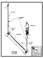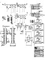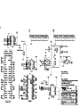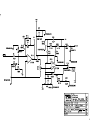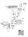
1
TRANSPORTABLE PORTAL MONITOR
MODEL TSA TPM-903B
Operations & Service Manual
Doc: # 5058 Rev. A
March 2013
LAURUS Systems, Inc. - Ph: 410-465-5558 - Fax: 410-465-5257 - www.LaurusSystems.com
TSA TPM903 Operations and Service Manual
Doc: # 5058 Rev. A
_____________________________________________________________________________________________________________________
STANDARD WARRANTY FOR RAPISCAN SYSTEMS INSTRUMENTS
Rapiscan Systems warrants this instrument to be free from defects in workmanship and materials
for a period of twelve months from the date of shipment, provided that the equipment has been
used in a proper manner and not subjected to abuse. At Rapiscan’s option, repairs or
replacements will be made on in-warranty instruments without charge at the Rapiscan factory.
Warranty of sub-systems made by other manufacturers will be extended to Rapiscan customers
only to the extent of the manufacturer’s liability to Rapiscan. Rapiscan reserves the right to
modify the design of its product without incurring responsibility for modification of previously
manufactured units. Since installation conditions are beyond the company’s control, Rapiscan
does not assume any risks or liabilities associated with methods of installation or with
installation results.
Every effort is made to keep the manuals up to date and accurate. However, because Rapiscan
Systems is constantly improving and upgrading the product line, Rapiscan can make no
guarantee as to the content of current manuals. No obligations are assumed for notice of change
or future manufacture of these instruments.
Manufactured by
Rapiscan Systems
14000 Mead St.
Longmont, Colorado 80504 USA
Phone: +1.970.535.9949
Fax: +1.970.535.3285
[email protected]
_____________________________________________________________________________________________________________________
This document is the exclusive property of Rapiscan Systems.
Unauthorized use or distribution is strictly prohibited
TSA TPM903 Operations and Service Manual
Doc: # 5058 Rev. A
_____________________________________________________________________________________________________________________
List of Affected Pages
The pages and drawings listed below have been changed. The manual has been updated to
standardize this documentation.
Title: TSA TPM903 Operations and Service Manual
Date: March 2013
Pages: All
_____________________________________________________________________________________________________________________
This document is the exclusive property of Rapiscan Systems.
Unauthorized use or distribution is strictly prohibited
TSA TPM903 Operations and Service Manual
Doc: # 5058 Rev. A
_____________________________________________________________________________________________________________________
Table of Contents
1.0 INTRODUCTION........................................................................................................1 1.1. SCOPE AND PURPOSE OF MANUAL .......................................................................1 1.2. GENERAL DESCRIPTION ...........................................................................................1 1.3. SPECIFICATIONS .........................................................................................................2 2.0 INSPECTION AND SET-UP ......................................................................................3 2.1. INSPECTION .................................................................................................................3 2.1.1. DAMAGE CLAIMS .................................................................................................... 3 2.1.2. STORAGE.................................................................................................................... 3 2.1.3. SHIPPING .................................................................................................................... 3 2.2. SITE SELECTION AND PREPARATION ...................................................................3 2.3. ASSEMBLING THE SYSTEM TO SCAN PEDESTRIANS ........................................5 2.4. ASSEMBLING THE SYSTEM TO SCAN VEHICLES (OPTIONAL)........................7 3.0 SET-UP AND PROGRAMMING ...............................................................................8 3.1. START-UP AND SELF TEST .......................................................................................8 3.2. SET-UP ...........................................................................................................................8 3.3. PASSWORD CONTROL ...............................................................................................9 3.4. PROGRAMMING THE SYSTEM.................................................................................9 3.4.1. PARAMETERS.......................................................................................................... 11 3.4.2. FUNCTIONS.............................................................................................................. 15 3.5. PC COMMUNICATION ..............................................................................................22 3.6. INSTALLING THE SOFTWARE................................................................................22 3.7. TAB...............................................................................................................................22 3.8. PARAMETERS ............................................................................................................22 3.9. SHOW COUNT ............................................................................................................23 3.10. HISTORY ...................................................................................................................24 3.11. INITIAL INSTALLATION CHECKLIST .................................................................26 4.0 THEORY OF OPERATION ......................................................................................28 4.1. OVERVIEW .................................................................................................................28 4.2. MODES.........................................................................................................................30 4.2.1. SELF-TEST MODE ................................................................................................... 30 4.2.2. BACKGROUND MODE ........................................................................................... 30 4.2.3. FAST COUNT MODE............................................................................................... 31 4.2.4. VARIANCE ANALYZER MODE ............................................................................ 31 4.3. COMPONENTS............................................................................................................32 5.0 MAINTENANCE.......................................................................................................33 5.1. TPM Controller .............................................................................................................33 5.2. VARIANCE ANALYZER MODE...............................................................................33 5.3. WALK THROUGH TEST............................................................................................33 5.4. PERFORMANCE VERIFICATION CHECKLIST .....................................................35 5.5. RECOMMENDED SPARE PARTS............................. Error! Bookmark not defined. 6.0 TROUBLESHOOTING .............................................................................................37 6.1. COMPONENT ACCESS..............................................................................................37 6.2. COMPONENT TROUBLESHOOTING ......................................................................39 _____________________________________________________________________________________________________________________
This document is the exclusive property of Rapiscan Systems.
Unauthorized use or distribution is strictly prohibited
TSA TPM903 Operations and Service Manual
Doc: # 5058 Rev. A
_____________________________________________________________________________________________________________________
6.2.1.TPM CONTROLLER ................................................................................................. 39 6.2.2.DETECTOR ASSEMBLIES....................................................................................... 39 6.2.3. INFRARED DETECTOR .......................................................................................... 39 7.0 GLOSSARY...............................................................................................................40 8.0 PARTS LISTS............................................................................................................42 1.1 SPARE PARTS ORDERING INFORMATION........................................................42 9.0 LIST OF DRAWINGS ...............................................................................................43 _____________________________________________________________________________________________________________________
This document is the exclusive property of Rapiscan Systems.
Unauthorized use or distribution is strictly prohibited
TSA TPM903 Operations and Service Manual
Doc: # 5058 Rev. A
_____________________________________________________________________________________________________________________
CONFIGURATION TRACKING SHEET
RAPISCAN MODEL NUMBER:______________ SERIAL NUMBER:________________
SOFTWARE VERSION:______________ DATE RECEIVED:________________
OPTIONS AND ACCESSORIES:_________________________________________
SYSTEM MODIFICATIONS
MODIFICATION: _______________________________________________________
_______________________________________________________________________
INSTALLED BY:________________________________ DATE: ________________
MODIFICATION: _______________________________________________________
_______________________________________________________________________
INSTALLED BY:________________________________ DATE: ________________
MODIFICATION: _______________________________________________________
_______________________________________________________________________
INSTALLED BY:________________________________ DATE: ________________
MODIFICATION: _______________________________________________________
_______________________________________________________________________
INSTALLED BY:________________________________ DATE: ________________
MODIFICATION: _______________________________________________________
_______________________________________________________________________
INSTALLED BY:________________________________ DATE: ________________
TSA TPM903 Operations and Service Manual
Doc: # 5058 Rev. A
_____________________________________________________________________________________________________________________
1.0 INTRODUCTION
1.1. SCOPE AND PURPOSE OF MANUAL
This manual is designed to enable operating and service personnel to properly operate and care
for the TPM-903B. Since applications are necessarily site-specific, operation procedures are
given in general terms. Service and repair are covered to the board level. Anything more complex
than this requires that the instrument or assembly be returned to Rapiscan Systems.
1.2. GENERAL DESCRIPTION
The Personnel Portal Monitor, Model TPM-903B, is a highly reliable system for the detection of
radioactive isotopes. The TPM-903B can be used to monitor personnel or, with an optional
vehicle adapter kit, vehicles. It can be set up quickly with a minimum of training.
When the portal is not occupied, the system will automatically monitor background radiation and
periodically update a visual display on the controller. When a person enters the portal, the system
begins fast count monitoring and will alarm if the count exceeds a predetermined alarm level.
The system will also alarm if the background radiation level exceeds or falls below preset limits.
The system consists of two vertical pillars and an overhead cross-piece, which serves as an
interconnect. The pillars are made of PVC cell core pipe to provide adequate strength and light
weight. The system electronics are mounted on one of the vertical pillars, this pillar is considered
to be the "master pillar" The pillar spacing is fixed at 32" to provide adequate clearance for
wheelchairs. The TPM-903B may be powered by six "D" sized alkaline cells which provide at
least 24 hours of continuous operation; or from 100 - 240 Vac, 50 - 60 Hz power using the power
supply included with the system.
Each pillar contains a radiation detector assembly and detector module. The system controller
and occupancy detector are mounted on one of the vertical pillars.
_____________________________________________________________________________________________________________________
This document is the exclusive property of Rapiscan Systems.
Unauthorized use or distribution is strictly prohibited
1
TSA TPM903 Operations and Service Manual
Doc: # 5058 Rev. A
_____________________________________________________________________________________________________________________
1.3. SPECIFICATIONS
Detectors:
One 3" x 72" x 1.5" (7.5 x 180 x 3.8cm) organic plastic scintillator in each pillar, for a total
detector volume of 648in3 (10.6 liters) per system
Sensitivity:
1µCi of 137Cs
Power:
Six "D" size alkaline cells provide >24 hours of continuous operation, or 100 - 240V, 50 - 60Hz
power at .7 amps.
Passage Time:
Normally 0.5 seconds on a walk-through basis
Serviceability:
Self-checking routines and easily performed tests simplify board level trouble shooting. The
modular design allows quick and easy repair and maintenance.
Weight:
Approximately 100 lb. (45kg) total
Dimensions:
Two, 4.5" diameter x 84" high pillars (11 x 213cm), with a 4.5" (11cm) diameter crossover which
provides 32" (81cm) pillar spacing
_____________________________________________________________________________________________________________________
This document is the exclusive property of Rapiscan Systems.
Unauthorized use or distribution is strictly prohibited
2
TSA TPM903 Operations and Service Manual
Doc: # 5058 Rev. A
_____________________________________________________________________________________________________________________
2.0 INSPECTION AND SET-UP
The following procedures should allow on-site personnel to correctly set up the TPM-903B for
normal operation. Follow the procedures in the order given. A Checklist is included at the end of
Section 3. It is recommended that a copy of this be filled out after initial installation and
whenever the TPM-903B is put into service after prolonged storage.
2.1. INSPECTION
Immediately inspect the instrument for mechanical damage, scratches, dents or other defects. It
should be examined for evidence of concealed as well as external damage.
2.1.1. DAMAGE CLAIMS
If the instrument is damaged in transit or fails to meet specifications upon receipt, notify the
carrier and Rapiscan Systems immediately. Shipping cartons, packing materials, waybills and
other such documentation should be preserved for the carrier’s inspection. Rapiscan will assist in
providing replacement or repair of the instrument if necessary.
2.1.2. STORAGE
If the instrument is to be stored for any length of time, disconnect power to the instrument and
remove the batteries. Care should always be taken to avoid subjecting the instrument to severe
mechanical or environmental shock. The instrument should be stored in a dry, temperature
controlled location.
2.1.3. SHIPPING
Before returning the instrument for any reason, notify Rapiscan Systems of the difficulty
encountered, giving the model and serial numbers of the equipment. Rapiscan will furnish
specific shipping instructions.
2.2. SITE SELECTION AND PREPARATION
Select a smooth, level site with enough space to accommodate the system and provide access for
the personnel to be scanned.
_____________________________________________________________________________________________________________________
This document is the exclusive property of Rapiscan Systems.
Unauthorized use or distribution is strictly prohibited
3
TSA TPM903 Operations and Service Manual
Doc: # 5058 Rev. A
_____________________________________________________________________________________________________________________
2.3. ASSEMBLING THE SYSTEM TO SCAN PEDESTRIANS
1. Unzip the storage bag or unlatch the hard case and remove the pieces. There will be two
vertical pillars, two foot plates, and a cross piece.
2. Attach the vertical pillars to the foot plates with the washers and wing-nuts.
3. Feed the two shorter RJ-45 cables through the crossover tube and out the small hole below the
elbow.
4. Verify that the power switch is in the "Off" position. If the system is to be operated on
batteries, install a fresh set of "D" cells at this time. Otherwise, make sure an ac power source is
available.
5. Stand the two vertical pillars upright, approximately 32" apart. Orient the pillars so that the
serial number labels are facing each other.
6. Connect the RJ-45 connectors to the mating connectors on the vertical pillars. The small hole
below the elbow of the crosspiece should face the pillar with the controller.
7. Align the vertical pillars with the cross piece and slide the cross piece down onto the vertical
pillars until it is firmly seated.
8. Connect the two RJ-45 cables to the connectors marked 1 and 2 on the controller.
9. If ac power is to be used, connect the power supply output to the corresponding connector on
the TPM Controller, and plug the power supply into an ac outlet.
10. The system may be powered up, checked out, and programmed.
11. Attach the IR to the controller backplate using the supplied wing-nuts. The IR may be
positioned to face straight across or 45 degrees down. This adjustment may be necessary to avoid
triggering on people or vehicles outside the detection portal. Even with the IR pointing 45
degrees down it may not detect a very short person or an animal such as a dog. If this situation is
encountered then the system controller may be manually put into constant occupancy by pressing
the star (*) key on the keypad. To disable constant occupancy and return the unit to normal
operation press the pound key (#) on the keypad.
_____________________________________________________________________________________________________________________
This document is the exclusive property of Rapiscan Systems.
Unauthorized use or distribution is strictly prohibited
4
TSA TPM903 Operations and Service Manual
Doc: # 5058 Rev. A
_____________________________________________________________________________________________________________________
2.4. ASSEMBLING THE SYSTEM TO SCAN VEHICLES (OPTIONAL)
1. Unzip the storage bag or unlatch the hard case and remove the pieces. There will be two
vertical pillars, two foot plates, and a cross piece. If the vehicle scanning option was purchased,
there will be two larger foot plates, two caps for the vertical pillars and a cross over cable with
protective cover.
NOTE: The large foot plates will not fit in the storage bag, so they will be stored separately.
2. Attach the vertical pillars to the large foot plates with the washers and wing-nuts.
3. Stand the two vertical pillars upright, approximately 10 feet apart. Orient the pillars so that the
serial number labels are facing each other.
4. Connect the RJ-45 connector to mating connector at the top of the #1 pillar. Install one of the
slotted caps on this pillar. Connect the other end of the cable to the "1" input on the system
controller.
5. Connect the #2 cable to the detector and the "2" input on the system controller. Install the
second slotted cap over the top.
6. Verify that the power switch is in the "Off" position. If the system is to be operated on
batteries, install a fresh set of "D" cells at this time. Otherwise, make sure an ac power source is
available.
7. If ac power is to be used, connect the power supply output to the corresponding connector on
the TPM Controller, and plug the power supply into an ac outlet.
8. The system may be powered up, checked out, and programmed.
9. Attach the IR to the controller backplate using the supplied wing-nuts. The IR should be
positioned to face straight across the vehicle portal. The distance adjustment on the back of the
IR should be set to its maximum range.
_____________________________________________________________________________________________________________________
This document is the exclusive property of Rapiscan Systems.
Unauthorized use or distribution is strictly prohibited
5
TSA TPM903 Operations and Service Manual
Doc: # 5058 Rev. A
_____________________________________________________________________________________________________________________
3.0 SET-UP AND PROGRAMMING
3.1. START-UP AND SELF TEST
Turn on the power switch located on the side of the TPM-903B controller. The unit will reset and
clear the system, then perform a Power On Self-Test (POST) which takes approximately ten
seconds. The tests are displayed on the screen as they are run, if any test fails, the system will be
halted. The problem must be corrected before operation can commence.
The alarm will be turned on for about four seconds. If all the tests have been completed
successfully the system will go into the BACKGROUND Mode. The initial background
acquisition takes twenty seconds.
When the background is complete, system status will be displayed. The status screen consists of
four lines:
GAMMA = nnnn (background or COUNT, in CPS)
READY (system status, READY, TAMPER, OCCUPIED)
# OCC: (number of occupancies)
mm/dd/yy hh:mm (date and time)
The system is now ready for programming and set-up.
3.2. SET-UP
The TPM-903B is fully calibrated at the factory. It is possible that these adjustments may be
affected during shipment, so the calibration should be verified using the Field Calibration
Procedures in Section 5.1.
The TPM-903B controller is a variation of the SC-770, a general purpose controller that is used
in several different systems. It has many user programmable parameters that can be used to
optimize it for a wide variety of applications. Refer to Section 3.4 for details on programming the
controller.
_____________________________________________________________________________________________________________________
This document is the exclusive property of Rapiscan Systems.
Unauthorized use or distribution is strictly prohibited
6
TSA TPM903 Operations and Service Manual
Doc: # 5058 Rev. A
_____________________________________________________________________________________________________________________
3.3. PASSWORD CONTROL
The zero (0) key on the keypad is used to enter the set-up mode from the operating screen. Before
the menus can be accessed, the password must be input, followed by the pound (#) key. If the
password in not entered correctly, the system will return to the operating screen.
NOTE: The password is set to "1234" and cannot be changed.
3.4. PROGRAMMING THE SYSTEM
CAUTION
Always verify the calibration of the system before attempting to program the system.
All of the system parameters are controlled from the system controller which is mounted on the
"#1" pillar. In order to access the TPM-903B, the cover must be removed by removing the four
screws in the corners of the clear cover.
The TPM-903B has a twelve-key keypad on the front panel. Using this keypad, the operator can
perform system set-up and diagnostic tests.
After the system has been powered up, and acquired its initial background, the set-up menu can
be accessed. The parameters and diagnostic functions are protected by password access.
This section outlines the menus. A detailed description of the functions immediately follows.
Pressing the number associated with the desired operation permits the operator to access that
function. Pressing the zero key will display the next page of the current menu, where appropriate.
Pressing the pound (#) key will return to the main menu from the sub menus, or return to normal
operation if it is pressed at the main set-up menu.
When a parameter is with a "NEW =" prompt below it, a new value may be entered from the
keypad. Pressing the asterisk (*) key clears the current operator entry, pressing the pound (#) key
accepts the current value, or the new value that has been entered by the operator.
The set-up menu presents the operator with a choice of parameters or functions. Pressing the
"one" key will present a menu of the available PARAMETERS. Pressing the "two" key will
present a menu of the available FUNCTIONS.
_____________________________________________________________________________________________________________________
This document is the exclusive property of Rapiscan Systems.
Unauthorized use or distribution is strictly prohibited
7
TSA TPM903 Operations and Service Manual
Doc: # 5058 Rev. A
_____________________________________________________________________________________________________________________
3.4.1. PARAMETERS
To access PARAMETERS you will first have to press “0” followed by the password. The next
screen gives you two options, 1. GAMMA and 2. COMM SET. Press 1 on the keypad. The next
screen that comes up will give you 1. PARAMETERS and 2. FUNCTIONS. Press 1 to give you
the following options:
1. HI/LO LEVELS: Background alarm levels
2. OCCUP HOLDIN: Number of 200ms intervals to hold in after occupancy
3. NSIGMA: N*sigma radiation alarm level
4. SET CLOCK: Time and date
5. BKG TIME: Number and position of detectors in the system
6. SHOW VERSION: Displays the firmware version
7. KEYPAD RESET: Changes from auto reset to manual reset
8. ADJ. DISCRIM Discriminator adjustment
3.4.1.1. HI/LO LEVELS: Sets the low and high background alarm levels, in CPS per detector. If
the counts fall outside this window, the system will indicate a background fault, and not allow
further operation until the problem is corrected. These levels should be set to alarm if the average
background deviates too far from normal. These alarms are intended to flag a failure in the
detector or electronics. The precise settings will vary with local conditions and requirements, but
a good starting point is usually 50% of the average background (per detector) for the low and
150% of the average background (per detector) for the high.
3.4.1.2. OCCUP HOLDIN
Number of 200ms intervals to hold in after the occupancy signal indicates the system is vacant.
This prevents the person from attenuating the background. The factory setting is 5 intervals
(1,000 milliseconds), but the optimum setting may vary with local conditions.
3.4.1.3. NSIGMA
Sets N*sigma radiation alarm level. Where N is the number entered and sigma = 1 background in
CPS. This formula determines the number of counts, above background, that will trigger a
radiation alarm.
3.4.1.4. SET CLOCK
Sets the system time and date. The operator will be prompted to enter the hours (in 24-hour
format), minutes, month, date, and year (last two digits only) from the keypad. When the pound
(#) key is pressed after the last entry, the data are written to the internal clock/calendar.
_____________________________________________________________________________________________________________________
This document is the exclusive property of Rapiscan Systems.
Unauthorized use or distribution is strictly prohibited
8
TSA TPM903 Operations and Service Manual
Doc: # 5058 Rev. A
_____________________________________________________________________________________________________________________
3.4.1.5. BKG TIME
Sets the background counting time for the system. Press <1> to increment the time by 5 seconds,
<7> to decrement the time by 5 seconds. Press <#> to accept the setting. Range is 20 - 120
seconds.
* If you have an area with large background fluctuations, you can increase the BKG Time to help
average out those bkg spikes over a longer period of time (say ~1 minute).
3.4.1.6. SHOW VERSION
Displays the software version number, press any key to return to the setup menu.
3.4.1.7. KEYPAD RESET
When enabled, requires any alarm to be silenced by using the keypad.
3.4.1.8. ADJ. DISCRIM
Opens the menu to adjust the LLD and ULD. The discriminators set the energy levels at which
the system will be accept counts. If the isotopes are unknown, leaving the discriminators set at
the factory defaults of 0.068 and 5.040 volts is normally acceptable. When the system is shipped
from the factory, the discriminators are set to accept energy in the approximate range of 22 keV
to 1650 keV. The settings are necessarily site specific, and may require adjustment to meet local
requirements. The relationship of discriminator voltage to energy level, in keV, is approximately
1 volt of discriminator level equals 330 keV. Using this formula, the factory settings equal:
LLD 0.068 volts = 22.4 keV
ULD 5.040 volts = 1,650 keV
This relationship is an approximation. In practice, the actual values will vary slightly. Always
test the system with the isotope(s) of interest to ensure maximum sensitivity. Refer to the formula
for signal to background ratio in Appendix A for details on optimizing the discriminator settings
for specific isotopes.
NOTE: After changing the discriminator settings, always run a variance test to ensure that
system noise is not affecting the count data.
Two methods of adjustment are provided:
1. Direct entry: Press the zero key from the "ADJUST ULD/LLD" menu. The operator will be
prompted for a new LLD setting. Press the pound (#) key to accept the current setting. Three
digits must be entered to change the value: volts, tenths of a volt and hundredths of a volt; press
the pound (#) key to complete the operation.
NOTE: Since the Digital to Analog Converters (DACs) have limited resolution, manual entries
will be rounded to nearest value the DACs can output.
_____________________________________________________________________________________________________________________
This document is the exclusive property of Rapiscan Systems.
Unauthorized use or distribution is strictly prohibited
9
TSA TPM903 Operations and Service Manual
Doc: # 5058 Rev. A
_____________________________________________________________________________________________________________________
2. Manual adjustment: At the "ADJUST ULD/LLD" menu, the discriminators may be adjusted
one step at a time while observing the count from both detectors.
The following keys are used:
1 increments the LLD by one step (approximately 0.0098 volts)
7 decrements the LLD by one step
3 increments the ULD by one step (approximately 0.0196 volts)
9 decrements the ULD by one step
When the settings are satisfactory, press the pound (#) key to accept the settings.
Pressing the asterisk (*) key will load the default discriminator settings: LLD = 0.098 and ULD =
5.040.
3.4.2. FUNCTIONS
1. SHOW COUNT: Displays detector counts
2. VARIANCE: Performs variance test on all detectors
3. CLEAR G-CNTS: Clears the counter of recorded gamma alarms
4. F-ALARM TEST: Displays the number of alarm comparisons vs. the number of alarms
5. SYSTEM ID: Assigns an identification number to the system
6. PROFILING: Turn ON or OFF an ASCII data string to the Ethernet and RS-232 outputs
7. CALIBRATION: Automatically adjusts each detector to achieve the proper CPS.
8. RESTORE CAL: Restores the factory calibration high voltage values.
3.4.2.1. SHOW COUNT
Displays detector counts, in CPS, updated once per second. All alarms are disabled in the show
count mode. Press the pound (#) key to exit the show count mode.
3.4.2.2. VARIANCE
Performs a variance test on all detectors. The system runs 15-second variance passes. In the
TPM-903B system, Rapiscan recommends running five 15-second passes. After five passes all
variance readings should be less than 0.10. Refer to Appendix A for further detail on the variance
test and the formulas used. Press the pound (#) key to terminate the variance test. Perform a
variance test and a walk-through test with a source (see Section 4) before the unit is put into
operation. For more information and recommended settings for different SNM types call
Rapiscan’s engineering staff.
3.4.2.3. CLEAR G CNTS:
The SC-770 counts the number of occupancies and alarms since it was turned on. These numbers
are displayed here. The counter may be cleared by pressing <1>, any other key exits this mode
without clearing the counters.
_____________________________________________________________________________________________________________________
This document is the exclusive property of Rapiscan Systems.
Unauthorized use or distribution is strictly prohibited
10
TSA TPM903 Operations and Service Manual
Doc: # 5058 Rev. A
_____________________________________________________________________________________________________________________
3.4.2.4. F-ALARM TEST:
Displays the number of alarm comparisons that have been made and the number of alarms that
were detected. These values are cleared when the system is turned off. The primary use for this
feature is to test the number of nuisance alarms in a controlled environment.
3.4.2.5 SYSTEM ID:
Assigns an identification number to the system. This number is used to uniquely identify the
system to a PC. This number must be used by the PC to establish a communications link. This
range of this number is 1 - 32,767. This number is set to 1 when the system is shipped.
_____________________________________________________________________________________________________________________
This document is the exclusive property of Rapiscan Systems.
Unauthorized use or distribution is strictly prohibited
11
TSA TPM903 Operations and Service Manual
Doc: # 5058 Rev. A
_____________________________________________________________________________________________________________________
3.4.2.6 PROFILING:
The controller can be set to continuously output an ASCII data string to the Ethernet and RS-232
outputs. The display will show "ON" or "OFF". Pressing any key other than the <#> key toggles
the setting. The <#> key accepts the current setting.
The strings look like this:
GB,XXXXXX,XXXXXX,XXXXXX,XXXXXX CRLF
Gamma background sent every 5 seconds. Counts are a 20 second rolling average normalized to
a one second count.
GH,XXXXXX,XXXXXX,XXXXXX,XXXXXX CRLF
Gamma high background fault sent every 5 seconds for the duration of the fault condition.
GL,XXXXXX,XXXXXX,XXXXXX,XXXXXX CRLF
Gamma low background fault sent every 5 seconds for the duration of the fault condition.
GS,XXXXXX,XXXXXX,XXXXXX,XXXXXX CRLF
TCP Ethernet output: Raw gamma count information sent every 200msec while the system is
occupied and not in an alarm condition.
RS-232 Output: Sent every second while the system is occupied and not in an alarm condition.
The counts are a one second count averaged from the 200msec rolling count buffer.
GA,XXXXXX,XXXXXX,XXXXXX,XXXXXX CRLF
TCP Ethernet output: Raw gamma count information sent every 200msec while the system is
occupied and in an alarm condition.
RS-232 Output: Sent every second while the system is occupied and in an alarm condition. The
counts are a one second count averaged from the 200msec rolling count buffer.
TT,000000, 000000, 000000, 000000 CRLF
Tamper or power fail condition detected. This is sent once when the following conditions occur;
ac power loss, charger output failure, or when the pillar doors are open. Fields are padded to 32
bytes.
TC, 111111,111111,111111,111111 CRLF
Tamper or power fail condition cleared. This is sent once when the following conditions occur;
ac power returned, or when the pillar doors are closed. Fields are padded to 32 bytes.
GX,XXXXXX,000000,000000,000000 CRLF
System occupancy count since midnight each day. xxxxxx = 1 – 99,9999 occupancies. This
message is sent with an incremented count every time the pillar clears the occupancy. This
variable is automatically cleared on a power cycle and at midnight each day. Fields are padded
for 32 bytes.
_____________________________________________________________________________________________________________________
This document is the exclusive property of Rapiscan Systems.
Unauthorized use or distribution is strictly prohibited
12
TSA TPM903 Operations and Service Manual
Doc: # 5058 Rev. A
_____________________________________________________________________________________________________________________
NOTE: PC Communications will not work (connect) when profiling is turned on.
3.4.2.7 CALIBRATION:
Required items: A Cs137 source with a depreciated value from 1uCi to 10uCi
The first thing the TPM controller does is to ask for the depreciated Cs137 activity of the source
that will be used for the calibration. If the user does not know the depreciated value of the
calibration source but does know when the source was manufactured, then the user can go to the
Rapiscan Systems web site (tsasystems.com) and look under archives/software/ SourceDepr to
determine the depreciated value. When entering a value less than 10 remember to enter a zero as
the first digit.
After the depreciated value has been entered the next screen is an information only screen that
will list the target counts that the controller will be using to perform the calibration.
The next thing the TPM controller does is take "roll call" to identify/verify the addresses of the
DM-757's. If the addresses haven't changed since the last time the unit was calibrated, it will
continue with the calibration. If it senses a conflict, the TPM controller will instruct the pillars
(DM-757's) to pick random addresses and will attempt to resolve the pillars. If communications
fail after 3 attempts, the controller will tell the user which pillar failed and halt operation. If
pillars are resolved successfully, calibration will continue.
After testing/resolving the pillars, the unit will flash both LED's and emit a short <beep>, then
the user will be prompted:
PLACE SOURCE
ON PILLAR 1
PRESS ANY KEY
After user presses a key
CALIBRATING
PILLAR 1
COUNTS: X
HVDAC: X
COUNTS are one second count data from the pillar.
HVDAC is the DAC value being sent to the pillar to adjust the high voltage.
_____________________________________________________________________________________________________________________
This document is the exclusive property of Rapiscan Systems.
Unauthorized use or distribution is strictly prohibited
13
TSA TPM903 Operations and Service Manual
Doc: # 5058 Rev. A
_____________________________________________________________________________________________________________________
If the HVDAC value reaches 1000 and target counts haven’t been achieved, the calibration will
fail because the HV is getting dangerously high (for the PMT). The unit will flash both LED’s,
emit a short <beep> and the user will be presented with a message:
PILLAR 1
FAILED CALIBRATION
PRESS ANY KEY
After pressing any key, the user will be returned to the menu. (No sense in continuing with the
calibration at this point).
If the calibration completes successfully, the user will be prompted to place the source on pillar 2
and repeat the process for that pillar.
At the end of a successful calibration, the unit will flash both LED’s, emit a short <beep> and the
user will be presented with a message:
CALIBRATION
COMPLETED
PRESS ANY KEY
After user presses key:
PILLAR 1
HVDAC: X
PRESS ANY KEY
After user presses key the same info will be presented for pillar 2
Pressing any key at this point returns to menu.
_____________________________________________________________________________________________________________________
This document is the exclusive property of Rapiscan Systems.
Unauthorized use or distribution is strictly prohibited
14
TSA TPM903 Operations and Service Manual
Doc: # 5058 Rev. A
_____________________________________________________________________________________________________________________
3.4.2.8 RESET CAL:
This routine restores the factory calibration HVDAC value. When pillar is calibrated at Rapiscan,
the HVDAC value is stored in the DM-757 in the pillar. If a calibration fails, the user may
attempt to recover by using the Reset Cal routine.
User is presented with:
RESET FACTORY
CALIBRATION
ON BOTH PILLARS
RESET: 1 ABORT: 3
If user presses 1:
The TPM controller sends a command to both pillars instructing the DM-757's to use the factory
calibration HVDAC value and presents the user with:
FACTORY
CALIBRATION
RESTORED
PRESS ANY KEY
Pressing key returns to the menu
If the user chose to abort by pressing 2, he/she is presented with:
RESET ABORTED
PRESS ANY KEY
Pressing key at this point returns to menu
_____________________________________________________________________________________________________________________
This document is the exclusive property of Rapiscan Systems.
Unauthorized use or distribution is strictly prohibited
15
TSA TPM903 Operations and Service Manual
Doc: # 5058 Rev. A
_____________________________________________________________________________________________________________________
3.5. PC COMMUNICATION
A communications package is shipped with each system. The package requires an IBM/PC
compatible computer running Microsoft Windows 98/ME or NT 4. The package allows the
operator to examine the system parameters and download data from the nonvolatile RAM.
The system will continue to operate normally during PC communications; however
communication will be suspended whenever the system is occupied.
WARNING
To ensure proper system operation, always close the communications program before
disconnecting the RJ-45 cable.
3.6. INSTALLING THE SOFTWARE
The program files can be found on the CD ROM stored on the last page of this manual. To install
the program, run "SETUP.EXE" on this disk. This will install the program on the host computer.
The default directory is "\Program Files\Bicron\TPMCOM\, press the "Browse" button to install
to a different directory.
3.7. TAB
After the installation is complete, the operator is given the option to run the program. Click on
the "Tab" button to select the communications port to be used. Each time the program is run, the
id number of the target system must be entered, then selected by clicking on the "Apply" button.
NOTE: The id number entered into the PC, and the id number stored in the system must be
identical. If they are not, communications cannot be established.
3.8. PARAMETERS
The program will automatically read the parameters from the system and display them on the
screen. The parameters cannot be changed from the PC.
3.9. SHOW COUNT
Displays detector counts, in CPS, updated and averaged over the most recent 5 second data.
_____________________________________________________________________________________________________________________
This document is the exclusive property of Rapiscan Systems.
Unauthorized use or distribution is strictly prohibited
16
TSA TPM903 Operations and Service Manual
Doc: # 5058 Rev. A
_____________________________________________________________________________________________________________________
3.10. HISTORY
When the system is operating, certain data are written to its internal, non-volatile RAM.
These data include:
Date and time stamp each time the system is powered up
The background is written each hour of operation, including date and time
Date and time stamp of each radiation alarm, including the detector counts and the background
used in the radiation alarm calculations
These data can be downloaded to a disk file in a PC by clicking on the "History" tab. The
operator will be given the option of downloading all records, or input the number desired. The
system can store up to 3,017 records.
The operator must provide a file name, and optionally, an extension. If no extension is given, the
program will use .LOG.
The data file is in ASCII text format, and will look something like this:
06/09/05 17:20:51 Power-up 0 0 0 0 0
06/09/05 17:21:51 Avg. Bkg. 1710 861 849 0 0
06/09/05 17:22:51 Avg. Bkg. 1989 998 991 0 0
06/09/05 17:24:52 Background 1997 1001 996 0 0
06/09/05 17:24:52 Rad Alarm 1951 981 970 0 0
15/09/05 19:37:59 Low Alarm 0 1257 8 0 0
After the download is complete, the operator will be prompted for a file name, and given the
option to view a file at this time.
_____________________________________________________________________________________________________________________
This document is the exclusive property of Rapiscan Systems.
Unauthorized use or distribution is strictly prohibited
17
TSA TPM903 Operations and Service Manual
Doc: # 5058 Rev. A
_____________________________________________________________________________________________________________________
3.11. INITIAL INSTALLATION CHECKLIST
___ Incoming inspection performed by: _______________________________________
___ 90 - 250 Vac 47 - 63 Hz power supply available.
___ Pillars vertical and square to each other.
___ Pillars stabilized.
___ Cabling correctly installed.
___ System calibration: ___ unchanged ___ new values:
Pillar #1: LLD set to: _______________ ULD set to: _______________
Pillar #2: LLD set to: _______________ ULD set to: _______________
Parameter settings:
Number of Detectors set to: _______________
Low Alarm level set to: _______________
High Alarm level set to: _______________
Occupancy hold-in set to: _______________
Alarm Comparison Intervals set to: _______________
Alarm level (N*Sigma) set to: _______________
Algorithm: Sum____ Horizontal____ Vertical____ Single____
Background level (N*Sigma) set to: _______________
Background Time: _______________
___ Electronic calibration required - ___ SC-771 ___ GHA-472
___ System starts up and runs initial self-test without errors.
___ All modes operational.
___ Background mode in operation area; count = ______________
___ Variance test; variance detector 1: _______ 2: _______
___Test; list sources and sizes used: ________________________________________
______________________________________________________________________
Performed by:_____________________________ Date: __________________
COMMENTS:________________________________________________________________
____________________________________________________________________________
____________________________________________________________________________
____________________________________________________________________________
_____________________________________________________________________________________________________________________
This document is the exclusive property of Rapiscan Systems.
Unauthorized use or distribution is strictly prohibited
18
TSA TPM903 Operations and Service Manual
Doc: # 5058 Rev. A
_____________________________________________________________________________________________________________________
4.0 THEORY OF OPERATION
4.1. OVERVIEW
The portal monitor makes its decisions for radiation alarms in the following manner. A level for
N*sigma is selected using the keypad. Whenever the occupancy detector senses that the monitor
is occupied, the monitor starts making alarm comparisons based on the parameters that have been
stored in the controller’s NVRAM (FAST COUNT mode).
When unoccupied, the portal monitor constantly updates the background count to reflect changes
in the environment. The background is accumulated in 5-second increments, with the current
background reading equal to the one-second average of the last four 5 second intervals. This
updates the background completely every 20 seconds. When the unit is occupied, it ignores the
current 5-second background interval, and goes into FAST COUNT mode.
The monitor collects its counts in 200 millisecond (0.2 sec.) intervals. For example, if the number
of intervals is set to 5, the alarm comparison will be based on 1.0 second counts. This sum of
counts is then compared to an alarm level which is normalized to that number of intervals.
The number of intervals should be selected based on an average walk speed of 1.5 meters/second
while passing through the monitor. The summed count of the chosen number of intervals should
reflect total occupancy time, and thus offer the maximum probability of detecting an alarm
condition.
While the monitor is occupied, it makes an alarm comparison every 200 milliseconds, based on
adding together the most recent n 200 millisecond intervals. The intervals are stored
continuously, so that as soon as the monitor is occupied, it waits for the current interval to end,
then adds up the selected number of intervals and makes an alarm comparison. This means that if
the monitor is set to five intervals, it is effectively starting to monitor the passage 1 second before
the monitor has been occupied. This is called "look back." The monitor will continue to make
comparisons until the "occupancy hold-in" time has expired after the end of the occupancy. This
is called "look after."
The "occupancy hold-in" forces the unit to continue to make alarm comparisons after the
occupancy detector has cleared (look after). The amount of time selected for this parameter is
based on the estimated speed of passage and pillar spacing.
_____________________________________________________________________________________________________________________
This document is the exclusive property of Rapiscan Systems.
Unauthorized use or distribution is strictly prohibited
19
TSA TPM903 Operations and Service Manual
Doc: # 5058 Rev. A
_____________________________________________________________________________________________________________________
4.2. MODES
4.2.1. SELF-TEST MODE
When the instrument is turned on, it performs a Power-On Self-Test (POST). The POST
performs the following tests:
RAM: Tests conventional memory, primarily the area used for the processor’s stack
NVRAM: Tests the battery-backed, non-volatile memory used to store parameters
LAMPS: The audio annunciator and both LEDs are turned on for approximately 4 seconds.
If any of these tests fails, the controller will display a "FAIL" message. The system cannot be put
into service until the problem is corrected.
After completing the POST, the system will enter the BACKGROUND mode and be ready to
operate after the initial 20-second background is obtained.
4.2.2. BACKGROUND MODE
BACKGROUND mode is the default mode for routine operation. The system will automatically
go to this mode after the initial self-test series. The display counts down from 19 to 0 during the
first background collection period. During this initial countdown, no other functions are
available, and occupancies are ignored. The unit then continuously takes 5-second background
counts and adds the most recent 4 together to display the most recent 20-second average (20second sliding background).
After the initial countdown, system status is displayed, and the system starts monitoring for
occupancy. The background display will update every five seconds to show the current
background being used for alarm calculations. While collecting background counts, the controller
compares the latest count with the high and low background alarm levels once a second. If the
background count is outside these limits, the unit will display DET X:LO/HI NNNN, where X is
the detector number, and NNNN is the current background for that detector.
_____________________________________________________________________________________________________________________
This document is the exclusive property of Rapiscan Systems.
Unauthorized use or distribution is strictly prohibited
20
TSA TPM903 Operations and Service Manual
Doc: # 5058 Rev. A
_____________________________________________________________________________________________________________________
4.2.3. FAST COUNT MODE
Upon occupancy, the system automatically goes into fast count mode. While this mode does not
take counts any faster, it does update the display more often - every second instead of every five
seconds - and begins testing for alarm conditions every 0.2 seconds. The controller also stores a
number of 0.2 second count intervals in RAM, so that it can "anticipate" occupancy and start
alarm comparisons before the subject actually enters the pillar.
The system may be forced into the fast count mode by pressing the asterisk(*) key on the keypad.
Pressing the pound (#) key returns the system to background mode.
Upon entering the fast count mode, the unit waits for the current interval to go to completion (0.2
seconds maximum), discards the oldest interval, adds the latest one, tests for alarm conditions,
and begins another 0.2 second collection interval. This cycle continues during manual FAST
COUNT, or during occupation and the "occupancy hold-in" period, which starts when the unit
goes out of occupancy. If an alarm condition occurs, the TPM-903B will hold the alarm on until
5 seconds after the alarm condition is cleared.
The radiation alarm level is calculated on the basis of variation from the background. The
formula for N*Sigma may be found in the Appendix .
CAUTION
Do not leave unit in this forced state for normal operation.
4.2.4. VARIANCE ANALYZER MODE
In this mode, the unit takes 75 0.2 second background counts and performs a variance calculation
on the data. A more detailed description of the variance test may be found in the Appendix.
_____________________________________________________________________________________________________________________
This document is the exclusive property of Rapiscan Systems.
Unauthorized use or distribution is strictly prohibited
21
TSA TPM903 Operations and Service Manual
Doc: # 5058 Rev. A
_____________________________________________________________________________________________________________________
4.3. COMPONENTS
1. The TPM Controller is installed on Pillar 1 of the two vertical pillars. It is made up of the
following components:
1.1. The SC-771 board is the computer board for the system, and uses program software to run
the unit and perform all functions. The SC-771 receives 12VDC from a dc to dc converter and
uses another dc-dc converter to supply the ±5 Vdc required by its on-board circuitry.
The SC-771 board uses highly integrated components. If a failure occurs in the digital portion of
the board, it must be replaced.
1.2. The GHA-472 board provides regulated dc high voltage to the voltage divider networks
which are attached to the photo-multiplier tube on the detectors.
2. The DA372 Detector Assembly consists of a plastic scintillation detector coupled to a photomultiplier tube through a plastic light pipe, plug-on base with voltage divider network and
mounting hardware. The gamma ray is converted to photons (scintillation), which are then
converted into a voltage pulse on the GHA-472 board.
3. The battery module consists of three battery holders which hold a total of six "D" size alkaline
cells. The system can also be operated from a 100 - 240 volt, 50 - 60Hz ac outlet.
4. The Infrared detector is a passive type occupancy detector.
5. Alarm LED and buzzer - A red LED and piezo-electric buzzer are used to indicate a Radiation
Alarm.
6. Ready LED - A green ready LED indicates the monitor is on and ready to scan.
_____________________________________________________________________________________________________________________
This document is the exclusive property of Rapiscan Systems.
Unauthorized use or distribution is strictly prohibited
22
TSA TPM903 Operations and Service Manual
Doc: # 5058 Rev. A
_____________________________________________________________________________________________________________________
5.0 MAINTENANCE
Once initial installation has been completed, little maintenance is required. Periodic inspection is
recommended to insure proper functioning. This should include (but is not limited to):
-visual inspection for loose wires, etc.
-field calibration
-checking the settings of the control module
-running a variance test
-performing a walk-through test
A Performance Verification Checklist is included at the end of this section. It is recommended
that a copy of this be filled out whenever the TPM-903B is put into service after tuning and
recalibration.
5.1. TPM Controller
The display contrast may change slightly with outside temperature variations. If the display is
difficult to read, adjust the “R1” potentiometer on the SC-771 board. Refer to Drawings 6 and 10
for component locations.
5.2. VARIANCE ANALYZER MODE
After calibration is complete, a variance test should be performed. The variance analyzer will
identify many problems such as noise or light leaks with both the detectors and associated
electronics. Be sure to restrict all movement in the area while performing a variance test.
In the TPM-903B system after five updates all variance readings should be less than 0.10. Refer
to the Appendix for further detail on the variance test and the formulas used. Press the pound (#)
key to terminate the variance test.
5.3. WALK THROUGH TEST
Due to the many different environments and materials being monitored, the walk through test
will vary from site to site, although several general principles apply in all cases. Select an
appropriate source, and instruct the test subject to walk at the normal speed for testing personnel,
carrying the source alternately at belt level, at head level (under a hat), and at shoe or ankle level.
Repeat the test several times and record the sources and sizes used.
_____________________________________________________________________________________________________________________
This document is the exclusive property of Rapiscan Systems.
Unauthorized use or distribution is strictly prohibited
23
TSA TPM903 Operations and Service Manual
Doc: # 5058 Rev. A
_____________________________________________________________________________________________________________________
5.4. PERFORMANCE VERIFICATION CHECKLIST
___ Repairs made (if any): list component and type of repair:
___ System calibration: _____ unchanged ______ new values:
LLD set to: _______________ ULD set to: _______________
Parameter settings:
Low Alarm set to: ______________
High Alarm set to: ______________
Occupancy hold-in set to: ______________
Alarm Comparison Interval set to: ______________
Sigma set to: ______________
___ Electronic calibration:
SC-771: ______ GHA-472: ______
___ System starts up and runs initial self-test without errors.
___ All modes operational
___ Background mode in operation area: count = _______________
___ Variance test; variance = 1: _______ 2: _______
___ Walk-through test; list test source serial number and activity:
Performed by: _____________________________ Date: ______________
COMMENTS:________________________________________________________________
____________________________________________________________________________
____________________________________________________________________________
____________________________________________________________________________
____________________________________________________________________________
____________________________________________________________________________
____________________________________________________________________________
____________________________________________________________________________
_________________________________________________________________________
_____________________________________________________________________________________________________________________
This document is the exclusive property of Rapiscan Systems.
Unauthorized use or distribution is strictly prohibited
24
TSA TPM903 Operations and Service Manual
Doc: # 5058 Rev. A
_____________________________________________________________________________________________________________________
5.5. RECOMMENDED SPARE PARTS
The list of spare parts given here is based on the following assumptions. One - that the maximum
downtime allowable is 2 hours. Two -that a technical background is not needed to perform the
repairs.
TSA Mfr’s
Qty. Stock#
Description
Mfr.
Part#
1
1
1
1
1
1
Detector Assembly
SC-771 Circuit Board
Infrared Detector
Power Supply, 7V
TPM-903B Controller
D Cell Battery Holder
TSA
TSA
Banner
TSA
TSA
Bulgin
8233C
8753
QS30DQ
7491B
9480B
BX0017
8233C
8753
6668
7491B
9480
6466D
_____________________________________________________________________________________________________________________
This document is the exclusive property of Rapiscan Systems.
Unauthorized use or distribution is strictly prohibited
25
TSA TPM903 Operations and Service Manual
Doc: # 5058 Rev. A
_____________________________________________________________________________________________________________________
6.0 TROUBLESHOOTING
This guide is designed so that on-site personnel can service the TPM-903B and effect necessary
minor repairs. It covers procedures and parts down to the board level. Any other problems should
be referred to Rapiscan’s technical staff.
When a problem occurs, it is important to isolate the cause as much as possible. This is
accomplished by a step by step procedure which checks each of the assemblies for proper
function and works upwards through the system.
Begin with a physical inspection of the unit, then check the power supply and cabling. Examine
the exterior of the enclosure for physical damage, faulty wiring, loose connections, etc. Open the
enclosure and do the same inside, checking all wiring. If the physical inspection shows no
obvious cause for the problem, proceed by checking the detectors, controllers, and other
individual assemblies, as outlined in the following steps.
After repairs have been made, a field calibration must be performed. (See Section 3.4.2.7.
Calibration.)
6.1. COMPONENT ACCESS
The TPM Controller is mounted on the "#1" vertical pillar (Drawing 1).
The IR occupancy detector is mounted on the controller on the "#1" pillar. To remove the
occupancy detector, remove the two wing-nuts holding the mounting bracket to the controller
back plate. Disconnect the connector, and the electronic assembly will be freed. Replace the
electronic assembly and reverse the process to reassemble the detector.
The LEDs are installed on the mounting plate for the controller circuit board. Desolder the wires
and remove the LED.
Install the replacement LED, and resolder the wires.
The pillars contain the detector assemblies, the detector module, and the high voltage module.
Verify problems by substituting the detectors. Return the defective pillar to Rapiscan for repair.
_____________________________________________________________________________________________________________________
This document is the exclusive property of Rapiscan Systems.
Unauthorized use or distribution is strictly prohibited
26
TSA TPM903 Operations and Service Manual
Doc: # 5058 Rev. A
_____________________________________________________________________________________________________________________
6.2. COMPONENT TROUBLESHOOTING
6.2.1.TPM CONTROLLER
The controller’s function is to receive the detectors digital pulses for counting and processing.
which are amplified and discriminated by the detector module.
Physically inspect the unit for harness wiring or connector problems. This procedure does not
cover the replacement of wires or connectors. Such replacement should only be done by
qualified service personnel. Questions concerning parts or wire type and availability may be
addressed to Rapiscan’s technical staff.
If a problem is suspected in the controller, replace it with a known good assembly, either from
spare parts or from another unit.
6.2.2. DETECTOR ASSEMBLIES
The detector assemblies have a detector module, high voltage module, and plastic scintillator
detector mounted inside. This assembly is difficult to remove and then get reinserted into the
PVC tube without damaging any of the parts. It is recommended that if a detector assembly is
defective that it be returned to Rapiscan for repair.
6.2.3. INFRARED DETECTOR
A green LED located on the top of the IR detector will illuminate on power up.
A yellow LED located on the top and back of the IR detector will illuminate when the detector
senses an object.
_____________________________________________________________________________________________________________________
This document is the exclusive property of Rapiscan Systems.
Unauthorized use or distribution is strictly prohibited
27
TSA TPM903 Operations and Service Manual
Doc: # 5058 Rev. A
_____________________________________________________________________________________________________________________
7.0 GLOSSARY
ADC: Analog to Digital Converter is an integrated circuit that converts an analog signal into a
binary number than can be used by the microprocessor.
CPS: Counts Per Second
High Background Alarm/Fault: The condition that occurs if the counts exceed the programmed
high background level. This condition prevents further operation until the problem is corrected.
Normally set in CPS.
LCD: Liquid Crystal Display
LED: Light Emitting Diode
LLD: The Lower Level Discriminator provides an adjustable threshold that determines the
lowest signal level that will be accepted as a nuclear pulse by the system’s electronics. Some
systems have both upper and lower level discriminators that can be used to set a discriminator
window. The discriminator window can be used to effectively reduce the background counts, and
increase system sensitivity to certain isotopes.
Low Background Alarm or Low Background Fault: The condition that occurs if the counts
fall below the programmed low background level. This condition prevents further operation until
the problem is corrected. Usually set in CPS.
POST: Power On Self-Test
Rolling Background: This is the background accumulation method used in most of Rapiscan’s
instruments. Background accumulation is done in ten separate buffers, each buffer representing
1/10 of the total background time. As each buffer is filled, the background is updated. This
results in a background update at background time/10. Initial background accumulation requires
the full background time.
Standard Background: Standard background requires the full background time for the initial
background and updates.
ULD: The Upper Level Discriminator provides an adjustable threshold that determines the
highest signal level that will be accepted as a nuclear pulse by the system’s electronics. Some
systems do not have an ULD. Also see LLD.
_____________________________________________________________________________________________________________________
This document is the exclusive property of Rapiscan Systems.
Unauthorized use or distribution is strictly prohibited
28
TSA TPM903 Operations and Service Manual
Doc: # 5058 Rev. A
_____________________________________________________________________________________________________________________
8.0 PARTS LISTS
The parts list in this manual includes parts that were being used at the time this manual was
written. Parts for systems produced prior to this date may be different. It is recommended that for
older equipment you should contact Rapiscan Systems at [email protected].
1.1 SPARE PARTS ORDERING INFORMATION
To facilitate the processing of spare parts orders the following information is required.
Product Number
Product Serial Number
Rapiscan Stock number
Part description (from parts list)
When ordering programmed proms, the software version is required. This can be found on the
prom label.
NOTE:
Model number suffixes are generally not included in the text of the manual.
However, the suffixes in the parts lists must be included on orders for spare parts.
FOR ASSISTANCE CALL:
Rapiscan Systems
14000 Mead Street
Longmont, Colorado 80504 USA
Phone: +1.970.535.9949
Fax: +1.970.535.3285
Email: [email protected]
_____________________________________________________________________________________________________________________
This document is the exclusive property of Rapiscan Systems.
Unauthorized use or distribution is strictly prohibited
29
TSA TPM903 Operations and Service Manual
Doc: # 5058 Rev. A
_____________________________________________________________________________________________________________________
9.0 LIST OF DRAWINGS
TPM-903B Pedestrian Model Pictorial View..................................................................................................1
TPM-903B Vehicle Model Pictorial View......................................................................................................2
TPM-903B Wiring Diagram ...........................................................................................................................3
TPM-903B Controller Pictorial View .............................................................................................................4
TPM-903B Pictorial ........................................................................................................................................5
SC-771 System Controller PCB (Sheet 1 of 4) ...............................................................................................6
SC-771 System Controller PCB (Sheet 2 of 4) ...............................................................................................7
SC-771 System Controller PCB (Sheet 3 of 4) ...............................................................................................8
SC-771 System Controller PCB (Sheet 4 of 4) ...............................................................................................9
SC-771 Component Designator.....................................................................................................................10
DM-757 TPM Detector Module (Sheet 1 of 2) .............................................................................................11
DM-757 TPM Detector Module (Sheet 2 of 2) .............................................................................................12
DM-757 Board Component Designator ........................................................................................................13
GHA-472 Gamma High Voltage Analog Schematic Diagram (Sheet 1 of 2)...............................................14
GHA-472 Gamma High Voltage Analog Schematic Diagram (Sheet 2 of 2)...............................................15
GHA-472 Component Designator.................................................................................................................16
GPRB Wiring Diagram .................................................................................................................................17
GPRB Component Designator ......................................................................................................................18
TRAN-1 Differential Transmitter PCB .........................................................................................................19
TRAN-1 Component Designator...................................................................................................................20
VD-1924 Schematic Diagram .......................................................................................................................21
VD-1924 Component Designator..................................................................................................................22
_____________________________________________________________________________________________________________________
This document is the exclusive property of Rapiscan Systems.
Unauthorized use or distribution is strictly prohibited
30
CROSSOVER
#2
CONTROLLER
#1
CALIBRATION
SPOTS
#1
PILLAR "2"
#2
PILLAR "1"
TPM-903B
TPM-930B PEDESTRIAN
MODEL PICTORIAL VIEW
PEDESTRIAN MODEL
TPM-903B
DCN: EDCN
EDWG #
.xxx
UNLESS OTHERWISE NOTED.
REV. NA
TPM-903B_Manual12-08.tcw
PRoss
TPM903BPICT1
DM-757 AND
GHA-472
BOARDS
#2
PILLAR "2"
CALIBRATION
SPOTS
CONTROLLER
#1
DM-757 AND
GHA-472
BOARDS
CROSSOVER
#1
#2
10 FEET
DM-757 AND
GHA-472
BOARDS
TPM-930B VEHICLE
MODEL PICTORIAL VIEW
TPM-903B
DCN: EDCN
EDWG #
TPM-903B
VEHICLE MODEL
.xxx
UNLESS OTHERWISE NOTED.
REV. NA
TPM-903B_Manual12-08.tcw
PRoss
TPM903BPICT2
PILLAR "1"
GPRB-756
BATTERY
COMPARTMENTS
PILLAR '1' (REF)
READY
INDICATOR
POWER SWITCH
COMPUTER
CONNECTION
ALARM
INDICATOR
A
INFRARED
OCCUPANCY
DETECTOR
VIEW A
DISPLAY
PILLAR '2'
CONNECTION
FRONT OF
BOX (REF)
POWER INPUT JACK
(FOR OPERATION WITHOUT
BATTERIES)
B
AUDIO SONALERT
PILLAR '1'
CONNECTION
VIEW B
TPM-930B CONTROLLER
PICTORIAL VIEW
TPM-903B
TPM-903B CONTROLLER
EXTERNAL VIEW
DCN: EDCN
EDWG #
.xxx
UNLESS OTHERWISE NOTED.
REV. NA
TPM-903B_Manual12-08.tcw
PRoss
TPM903BPICT3
NUMERIC KEYPAD
(SETUP/DIAGNOSTICS)
DCN: EDCN
EDWG #
.xxx
UNLESS OTHERWISE NOTED.
REV. NA
DM-757B_CD.tcw
PRoss
DM757B_CD
DM-757B BOARD
COMPONENT DESIGNATOR
---
E-M-S
DCN: EDCN
EDWG #
REV. NA
GHA-472AA_8674AA_CD.tcw
DWG 11
.xxx
UNLESS OTHERWISE NOTED.
GHA-472AA CD
GHA-472AA CD