1
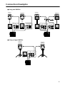
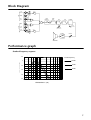
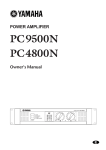
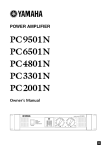
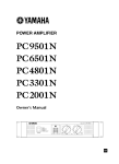
ENGLISH
SUBWOOFER
SW500
Owner’s Manual
Mode d’emploi
Bedienungsanleitung
Manual del Usuario
Thank you for purchasing a Yamaha SW500 subwoofer. The SW500 features a
reflex cabinet, with a 38 cm (15 inch) cone speaker. This powered subwoofer
reproduces a high-quality and powerful low-range sound. Please read this
Owner’s Manual thoroughly to make the best use of the SW500’s quality
functions for a long period of time, and keep the manual in a safe place.
Contents
Precautions .............................................. 3
Rear panel ................................................ 4
Connection Examples ............................... 5
Specifications ........................................... 6
Dimensions.............................................. 6
Block Diagram......................................... 7
Performance graph................................... 7
General specifications ..............................................6
Speaker unit ..............................................................6
Amp. unit .................................................................6
M
Precautions
• Use only the included power cord for this unit. Using
other types may be a fire and electrical shock hazard.
• Do not allow water to enter this unit or allow the unit
to become wet. Fire or electrical shock may result.
• Do not place a container with liquid or small metal
objects on top of this unit. Liquid or metal objects
inside this unit are a fire and electrical shock hazard.
• Connect the included power cord only to an AC outlet of the type stated in this Owner’s Manual or as
marked on the unit. Failure to do so is a fire and electrical shock hazard.
• Do not scratch, bend, twist, pull, or heat the power
cord. A damaged power cord is a fire and electrical
shock hazard.
• Do not place heavy objects, including this unit, on
top of the power cord. A damaged power cord is a
fire and electrical shock hazard. In particular, be
careful not to place heavy objects on a power cord
covered by a carpet.
• Place the device near a power outlet so you can easily plug it in.
• If you notice any abnormality, such as smoke, odor,
or noise, or if a foreign object or liquid gets inside the
unit, turn it off immediately. Remove the power cord
from the AC outlet. Consult your dealer for repair.
Using the unit in this condition is a fire and electrical
shock hazard.
• Should this unit be dropped or the cabinet be damaged, turn the power switch off, remove the power
plug from the AC outlet, and contact your dealer. If
you continue using the unit without heeding this
instruction, fire or electrical shock may result.
• If the power cord is damaged (i.e., cut or a bare wire
is exposed), ask your dealer for a replacement. Using
the unit with a damaged power cord is a fire and
electrical shock hazard.
• Do not remove the unit’s cover. You could receive an
electrical shock. If you think internal inspection, maintenance, or repair is necessary, contact your dealer.
• Do not modify the unit. Doing so is a fire and electrical shock hazard.
• If lightning begins to occur, turn off the power switch
of the unit as soon as possible, and unplug the power
cable plug from the electrical outlet.
• If there is a possibility of lightning, do not touch the
power cable plug if it is still connected. Doing so may
be an electrical shock hazard.
• Turn off all audio equipment, and speakers when
connecting to this unit. Use the correct connecting
cables and connect as specified.
• Do not subject the speaker to excessive levels, or distorted sounds (indicated by the clip indicator lighting
up often) as this leads to overheating and a possible
fire hazard.
• Always lower the volume control to minimum before
turning on the power to this unit. A sudden blast of
sound may damage your hearing.
• When rack-mounting the unit, allow enough free
space around the unit for normal ventilation. This
should be: 20 cm at the sides, 25 cm behind, and 30
cm above.
For normal ventilation during use, remove the rear of
the rack or open a ventilation hole.
If the airflow is not adequate, the unit will heat up
inside and may cause a fire.
• Do not use the handles to suspend the speaker. Otherwise, it may fall, causing injury.
• Hold the power cord plug when disconnecting it
from an AC outlet. Never pull the cord. A damaged
power cord is a potential fire and electrical shock
hazard.
• This unit is heavy. Use two or more people to carry it.
• Do not touch the power plug with wet hands. Doing
so is a potential electrical shock hazard.
• XLR-type connectors are wired as follows: pin 1:
ground, pin 2: hot (+), and pin 3: cold (–).
• Using a mobile telephone near this unit may induce
noise. If noise occurs, use the telephone away from
the unit.
• Do not use the speakers at uncomfortably loud level.
Otherwise, you may damage your hearing.
• Subwoofer SW500 comes with a metal socket for
installing the speaker stand. Use a speaker stand pole
that is one meter or shorter.
Troubleshooting
—If the unit shuts down during use—
If the CLIP indicator lights up often and you use this
unit for a long period of time, the thermostat inside
the power transformer will turn the power off. In
this case, turn the POWER switch off, wait for a
while (about one hour) until the the power transformer cools down, then resume using the unit at a
lower input level.
Be sure to lower the input level so that the CLIP
indicator lights up only momentarily.
3
Rear panel
D
C
SUBWOOFER CONTROL
POWER
SUBWOOFER
MODEL
SW500
100
80
0
CUTOFF
FREQ.
9
10
LEVEL
CLIP
0
E
NORM REV
PHASE
INPUT
OUTPUT
THRU
(+4dB)
OU TPUT
HIGH PASS
100Hz
(+4dB)
PARALLEL
POWER
ON / OFF
A
A
H
B
B
PARALLEL
AC IN
F
A POWER switch
This switch turns the power to the SW500 on and
off. When this switch is turned on, the green power
indicator (9) lights up.
B AC IN connector
Connect the included power cable here.
C CUTOFF FREQ. control
This control enables you to adjust the cutoff
frequency in the range of 80 through 100 Hz
depending on the speakers you are using with the
SW500 and your personal preferences.
D LEVEL control
This control enables you to adjust the sound
volume level. The maximum level is at the scale
setting of 10, and the minimum level is at the scale
setting of 0. If the level is too high, the CLIP
indicator (J) lights up red. In this case, lower the
level.
E PHASE switch
This switch enables you to select a phase. You will
usually set this switch to ”NORM”. However, the
”REV” setting may improve low-range sounds,
depending on the type and location of the entire
speaker system. Try both settings and select the one
with a better-sounding low-range output.
4
G
F INPUT jacks A and B
These are XLR-type balanced input jacks. Two
different signals can be input at these INPUT jacks
and routed to OUTPUT THRU jacks A and B and
OUTPUT HIGH PASS A and B jacks respectively. If
two signals are input at the same time, they are
mixed inside the subwoofer.
G OUTPUT THRU jacks A and B
These are XLR-type balanced output jacks. Connect
these jacks to another subwoofer to route signals
input from INPUT jacks A and B to the subwoofer.
H OUTPUT HIGH PASS jacks A and B
These are XLR-type balanced output jacks. Connect
these jacks to the main speakers to cut the range
below 100 Hz of signals input from INPUT jacks A
and B and route them to the main speakers.
I POWER indicator
This indicator lights up green when you turn the
POWER switch ON.
J CLIP indicator
This indicator lights up red if the output level is too
high. In this case, lower the level using the LEVEL
control or lower the input level.
Connection Examples
● Using two SW500s
Powered
speaker L
Main
speaker L
Powered
speaker R
Main
speaker R
Amp
TEMP
PROTECTION A
PROTECTION B
POWER
WATTS/8Ω
INPUT
1 0.1 1.0
0.0
5 10
CHANNEL A
WATTS/8Ω
CLIP/LIMIT
50 100
200
300
INPUT
1 0.1 1.0
0.0
5 10
CLIP/LIMIT
50 100
200
300
18
16
14
20 10 5 2 0 2 4
5
PEAK
30
50 40
+dB
20 10 5 2 0 2 4
5
PEAK
+dB
CHANNEL B
12
18
25
8
INPUT
OUTPUT
THRU
(+4dB)
OU TPUT
HIGH PASS
100Hz
INPUT
OU TPUT
HIGH PASS
100Hz
OUTPUT
THRU
(+4dB)
(+4dB)
INPUT
4
35
2
50
00
0
14
12
10
8
6
4
35
2
50
00
0
OFF
OU TPUT
HIGH PASS
100Hz
OUTPUT
THRU
(+4dB)
(+4dB)
16
25
6 30
30
CHANNEL B
POWER AMPLIFIER
PROFESSIONAL SERIES
20
10
20
30
50 40
CHANNEL A
ON/
INPUT
OUTPUT
THRU
(+4dB)
(+4dB)
PARALLEL
(+4dB)
PARALLEL
PARALLEL
PARALLEL
PARALLEL
PARALLEL
SW500
SW500
L
OU TPUT
HIGH PASS
100Hz
PARALLEL
PARALLEL
SW500
SW500
R
L
Mixer
R
Mixer
● Using a single SW500s
Powered
speaker L
Powered
speaker R
INPUT
OUTPUT
THRU
(+4dB)
OU TPUT
HIGH PASS
100Hz
(+4dB)
PARALLEL
PARALLEL
SW500
L
R
Mixer
5
Specifications
General specifications
Type
Bass Reflex powered subwoofer
Frequency Range
40–120 Hz (–10 dB)
Maximum Output Level
122 dB (1 m on Axis)
Dimensiones (W × H × D)
480 × 619 × 590 mm
Weight
37 kg
Installation pole diameter
35 mm (1.375”)
Accessories
Power cable 2.5 m (AC inlet type)
Controls
LEVEL Control
CUTOFF FREQ. Control: 80–100 Hz (Variable)
PHASE Switch: (REV/NORM)
POWER Switch: ON/OFF
Connectors
INPUT A ,B (XLR-3-31), OUTPUT THRU A, B (XLR-3-32)
OUTPUT HIGH PASS A ,B (XLR-3-32)
Power Indicator
Green LED
Clip Indicator
Red LED
Power Requirement
USA and Canada: AC 120 V, 60 Hz
Europe: AC 230 V, 50 Hz
Others: AC 240 V, 50 Hz
Power Consumption
200 W
★ 0 db=0.775 V
For European Model
Purchaser/User Information specified in EN55103-1
and EN55103-2.
Inrush Current: 70 A
Conformed Environment: E1, E2, E3 and E4
Speaker unit
Speaker Unit
38 cm cone (8Ω)
Enclosure
Type: Bass Reflex
Amp. unit
Maximum Output Power
500 W at 100 Hz, THD=1%, RL=8Ω
650 W at 100 Hz, 20 ms nonclip RL=8Ω
Input Sensitivity/Impedance
+4 dB/30 kΩ (channels A and B)
Specifications and appearance are subject to change
without notice.
250
Dimensions
590
619
480
Unit: mm
6
Block Diagram
100Hz
ch A
OUTPUT
(HIGH PASS)
HPF
OUTPUT
(THRU)
LOW
BOOST
INPUT
(+4dB)
LOW
CUT
LPF
LPF
PHASE
SUM
INPUT
(+4dB)
ch B
NORMAL
REVERSE
OUTPUT
(THRU)
CUTOFF FREQ
(80Hz to 100Hz)
100Hz
OUTPUT
(HIGH PASS)
HPF
P.AMP
LEVEL
BTL
SPEAKER
Performance graph
Standard frequency response
+10
Cutoff Frequency
100Hz
RESPONSE (dB)
0
90Hz
-10
80Hz
-20
-30
-40
20
100
1k
FREQUENCY (Hz)
7
YAMAHA CORPORATION
V792790 R0 1 IP 32
Printed in Taiwan
Pro Audio & Digital Musical Instrument Division
P.O. Box 3, Hamamatsu, 430-8651, Japan