1
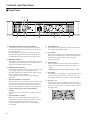
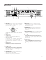
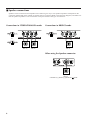
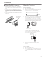
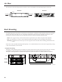
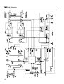
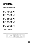
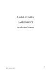
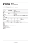
POWER AMPLIFIER
Owner’s Manual
E
FCC INFORMATION (U.S.A.)
1. IMPORTANT NOTICE: DO NOT MODIFY THIS UNIT! This product, when installed as indicated in the instructions contained in this manual, meets FCC
requirements. Modifications not expressly approved by Yamaha may void your authority, granted by the FCC, to use the product.
2. IMPORTANT: When connecting this product to accessories and/or another product use only high quality shielded cables. Cable/s supplied with this product MUST
be used. Follow all installation instructions. Failure to follow instructions could void your FCC authorization to use this product in the USA.
3. NOTE: This product has been tested and found to comply with the requirements listed in FCC Regulations, Part 15 for Class “B” digital devices. Compliance with
these requirements provides a reasonable level of assurance that your use of this product in a residential environment will not result in harmful interference with
other electronic devices. This equipment generates/uses radio frequencies and, if not installed and used according to the instructions found in the users manual, may
cause interference harmful to the operation of other electronic devices. Compliance with FCC regulations does not guarantee that interference will not occur in all
installations. If this product is found to be the source of interference, which can be determined by turning the unit “OFF” and “ON”, please try to eliminate the
problem by using one of the following measures: Relocate either this product or the device that is being affected by the interference. Utilize power outlets that are on
different branch (circuit breaker or fuse) circuits or install AC line filter/s. In the case of radio or TV interference, relocate/reorient the antenna. If the antenna lead-in
is 300 ohm ribbon lead, change the lead-in to coaxial type cable. If these corrective measures do not produce satisfactory results, please contact the local retailer
authorized to distribute this type of product. If you can not locate the appropriate retailer, please contact Yamaha Corporation of America, Electronic Service
Division, 6600 Orangethorpe Ave, Buena Park, CA 90620
The above statements apply ONLY to those products distributed by Yamaha Corporation of America or its subsidiaries.
• Explanation of Graphical Symbols
CAUTION
RISK OF ELECTRIC SHOCK
DO NOT OPEN
CAUTION: TO REDUCE THE RISK OF
ELECTRIC SHOCK, DO NOT REMOVE
COVER (OR BACK). NO USER-SERVICEABLE
PARTS INSIDE. REFER SERVICING TO
QUALIFIED SERVICE PERSONNEL.
The above warning is located on the
top of the unit.
The lightning flash with arrowhead symbol
within an equilateral triangle is intended to
alert the user to the presence of uninsulated
“dangerous voltage” within the product’s
enclosure that may be of sufficient magnitude to constitute a risk of electric shock to
persons.
The exclamation point within an equilateral triangle is intended to alert the user to
the presence of important operating and
maintenance (servicing) instructions in the
literature accompanying the product.
WARNING: THIS APPARATUS MUST BE EARTHED
IMPORTANT
THE WIRES IN THIS MAINS LEAD ARE COLOURED IN
ACCORDANCE WITH THE FOLLOWING CODE:
GREEN-AND-YELLOW :
EARTH
BLUE :
NEUTRAL
European Specifications Only
BROWN :
LIVE
This mark indicates a dangerous electrically live terminal.
When connecting an external wire to this terminal, it is
necessary either to have “a person who have received
appropriate guidance on handling” make the connection or to
use leads or a cord that have been manufactured in such a way
that the connection can be made simply and without problem.
As the colours of the wires in the mains lead of this apparatus may
not correspond with the coloured markings identifying the terminals in
your plug, proceed as follows:
The wire which is coloured GREEN and YELLOW must be
connected to the terminal in the plug which is marked by the letter E
or by the safety earth symbol
or coloured GREEN and YELLOW.
The wire which is coloured BLUE must be connected to the terminal
which is marked with the letter N or coloured BLACK.
The wire which is coloured BROWN must be connected to the
terminal which is marked with the letter L or coloured RED.
* This applies only to products distributed by YAMAHA KEMBLE
MUSIC (U.K.) LTD.
2
Precautions
WARNING
Installation
• Connect this unit’s power cord only to an AC outlet of the
type stated in this Owner’s Manual or as marked on the unit.
Failure to do so is a fire and electrical shock hazard.
• Do not allow water to enter this unit or allow the unit to
become wet. Fire or electrical shock may result.
• Do not place a container with liquid or small metal objects on
top of this unit. Liquid or metal objects inside this unit are a
fire and electrical shock hazard.
• Do not place heavy objects, including this unit, on top of the
power cord. A damaged power cord is a fire and electrical
shock hazard. In particular, be careful not to place heavy
objects on a power cord covered by a carpet.
• Use only the included power cord for this unit. Using other
types may be a fire and electrical shock hazard.
Operation
• Do not scratch, bend, twist, pull, or heat the power cord. A
damaged power cord is a fire and electrical shock hazard.
• Do not remove the unit’s cover. You could receive an
electrical shock. If you think internal inspection, maintenance,
or repair is necessary, contact your dealer.
• Do not modify the unit. Doing so is a fire and electrical shock
hazard.
• If lightning begins to occur, turn off the power switch of the
unit as soon as possible, and unplug the power cable plug
from the electrical outlet.
• If there is a possibility of lightning, do not touch the power
cable plug if it is still connected. Doing so may be an
electrical shock hazard.
In case an abnormality occurs during operation
• If the power cord is damaged (i.e., cut or a bare wire is
exposed), ask your dealer for a replacement. Using the unit
with a damaged power cord is a fire and electrical shock
hazard.
• Should this unit be dropped or the cabinet be damaged, turn
the power switch off, remove the power plug from the AC
outlet, and contact your dealer. If you continue using the unit
without heeding this instruction, fire or electrical shock may
result.
• If you notice any abnormality, such as smoke, odor, or noise,
or if a foreign object or liquid gets inside the unit, turn it off
immediately. Remove the power cord from the AC outlet.
Consult your dealer for repair. Using the unit in this condition
is a fire and electrical shock hazard.
3
CAUTION
Installation
• Keep this unit away from the following locations:
- Locations exposed to oil splashes or steam, such as near
cooking stoves, humidifiers, etc.
- Unstable surfaces, such as a wobbly table or slope.
Operation
• Use only speaker cables when connecting speakers to
amplifier outputs. Using other types of cables is a fire hazard.
• Do not use this amplifier for any purpose other than driving
loudspeakers.
- Locations exposed to excessive heat, such as inside a car
with all the windows closed, or places that receive direct
sunlight.
- Locations subject to excessive humidity or dust accumulation.
• Hold the power cord plug when disconnecting it from an AC
outlet. Never pull the cord. A damaged power cord is a
potential fire and electrical shock hazard.
• Do not touch the power plug with wet hands. Doing so is a
potential electrical shock hazard.
• This unit has ventilation holes at the rear to prevent the
internal temperature rising too high. Do not block them.
Blocked ventilation holes are a fire hazard.
• To relocate the unit, turn the power switch off, remove the
power plug from the AC outlet, and remove all connecting
cables. Damaged cables may cause fire or electrical shock.
• Allow enough free space around the unit for normal ventilation. This should be: 5 cm at the sides, 10 cm behind, and 10
cm above.
For normal ventilation during use, remove the rear of the rack
or open a ventilation hole.
If the airflow is not adequate, the unit will heat up inside and
may cause a fire.
• To mount several of these units in an EIA-compliant rack,
refer to the rack mounting instructions on page 10.
PRECAUTIONS FOR OPERATION
Connector pin assignments
• XLR-type connectors are wired as follows: pin 1: ground, pin
2: hot (+), and pin 3: cold (–).
4
– FOR CORRECT OPERATION –
Influence on cell phone usage
• Using a cell phone (mobile telephone) near this unit may
induce noise. If noise occurs, use the telephone away from the
unit.
Introduction
Thank you for purchasing a Yamaha PC9500N, or PC4800N Series Power Amplifier.
The PC Series of power amplifiers was developed from Yamaha’s wealth of experience in building
PA equipment and its tradition of careful attention to every detail of circuit design. These power
amplifiers feature high power and superb quality together with superior reliability and stability,
guaranteeing the highest possible audio performance.
Main features include
• Three modes are provided to support a broad range of applications: STEREO mode which
can be driven by two independent sources, PARALLEL mode in which a monaural source
drives both channels, and BRIDGE mode in which the two internal amps function as a single
mono amp.
• Balanced XLR connector and Euroblock connector inputs, and Speakon connector and fiveway binding post outputs are provided.
• A high pass filter switch that cuts frequencies below 40 Hz, and detented attenuators and
level meters for channels A and B are provided.
• Metering and indicators include easily visible two-channel level meters, a PROTECTION
indicator that shows the state of various protection systems (power on/off detection, output
protection, DC detection), a TEMP indicator that indicates heat sink overheating, and a
REMOTE indicator that indicates the external remote status.
• Variable-speed, low-noise cooling fan system ensures high reliability even under the most
demanding conditions.
This Owner’s Manual applies to the PC9500N and PC4800N power amplifier. In order to take
full advantage of your power amplifier and enjoy long and trouble-free operation, please read this
Owner’s Manual carefully before using your Power Amplifier.
Contents
Introduction ............................................................... 5
Controls and Functions ............................................. 6
Front Panel .......................................................... 6
Rear Panel ........................................................... 7
Speaker connections ........................................... 8
Connection ................................................................ 9
Using a Euroblock connector ............................... 9
Speaker Connection ............................................ 9
Air Flow ................................................................... 10
Rack Mounting ........................................................ 10
Specifications .......................................................... 11
General Specifications ....................................... 11
Block Diagram ................................................... 12
Dimensions ........................................................ 13
Troubleshooting ...................................................... 14
Performance graph ................................................. 14
5
Controls and Functions
■ Front Panel
234
7
1
5
1 POWER/STAND-BY switch and indicator
This turns the power of the amplifier on/off. When
you press the switch to turn on the power, the indicator will light green.
If the amplifier is connected to an external control
unit and the amplifier has been commanded to enter
STAND-BY mode, this indicator will light orange.
2 REMOTE indicator
This indicator will light green if the amplifier is being
controlled from an external device connected to the
DATA port located on the rear panel.
3 PROTECTION indicator
This indicator lights up red when the protection circuit
is operating. During this time, the amp will be
disconnected from the speaker system, and no sound
will be output from the speaker.
The protection system activates in the following
situations:
• When the amplifier is turned on
The protection system activates for approximately ten
seconds when the amplifier is turned on. After ten
seconds, the protection system deactivates automatically and the amplifier is ready for normal operation.
• If a DC voltage is detected at the amplifier’s
outputs
Turn off the power, and then turn the power back on
again.
• If the amplifier overheats
When this occurs, the TEMP indicator will be lit.
You should turn off the amplifier and allow it time to
cool down. See the Precautions section of this
Owner’s Manual for ways to prevent the amplifier
overheating.
6
6
8
7
4 TEMP indicator
This indicator will light red if the heat sink temperature exceeds 85 degrees Celsius.
5 Level meters
These are nine-segment level meters that indicate the
output level of output jacks A and B. If the distortion
of the output signal exceeds 1%, the red CLIP
indicator will light.
6 Volume knobs
These are detented volume knobs that attenuate the
input signals of channels A and B over a range of –∞
– 0 dB.
In BRIDGE mode, only the channel A knob is used.
7 Air intakes
The amplifier has a forced-air cooling fan that takes in
air from the front and exhausts it from the rear. You
must make sure that these intakes are not obstructed.
8 Security cover
If you want to keep the volume settings from being
modified, attach the included security cover using the
screw holes shown below, so that the volume controls
are inaccessible.
■ Rear Panel
1 2
3
5
6
4
8
7
1 XLR inputs
9
5 DATA ports
These balanced XLR-3-31 type connectors are used to
connect input signals. They are wired pin 1–ground,
pin 2–hot (+), and pin 3–cold (–).
An external control unit or interface box can be
connected here to monitor or control the amplifier
from the external device.
6 AMP ID switch
Hot
1
2
Ground
3
Cold
In Bridge mode, only the XLR input of the channel A
is active.
2 MODE switch
• STEREO mode
Channels A and B will operate independently.
• PARALLEL mode
In PARALLEL mode, the channel A input signal will
be sent to the channel A power amp and to the
channel B power amp. The channel B input jack is not
used.
• BRIDGE mode
In BRIDGE mode, channels A and B will operate
simultaneously, functioning as a single mono amp.
When an external control unit is connected to the
DATA port 5, this DIP switch is used to set the
system ID.
7 Euroblock connector
This is a balanced input jack. The included Euroblock
connector can be used to make connections here.
8 AC inlet
Connect the socket of the included AC cable to this
inlet. Connect the plug of the AC cable to an AC
outlet that meets the power supply conditions printed
below this inlet.
9 GND terminals
This is the grounding screw terminal. If hum or noise
occurs, ground (earth) the unit via this jack, or try
connecting it to the chassis of the mixer or preamp,
etc.
3 HPF 40 switches
These switches are used to turn on and off the HPF
(High Pass Filter) for each channel. When set to ON,
frequencies below 40 Hz are filtered using a 12 dB/
octave high pass filter.
4 SPEAKERS jacks
• These are Speakon type output jacks. Speakon type
cable plugs can be connected here.
• These are five-way binding post output jacks.
7
■ Speaker connections
Speakers can be connected to this amplifier in the following two ways. The speaker impedance will depend on the
connection method and on the number of speakers that are connected. Refer to the following diagrams, and make sure
that the speaker impedance is not less than the value prescribed for each type of connection.
Connections in STEREO/PARALLEL modes
Connections in BRIDGE mode
or
–
+
Speaker
min. 4Ω
+
–
Speaker
min. 4Ω
–
+
Speaker
min. 8Ω
When using the Speakon connector
Speaker
min. 8Ω
* Use the 1+(+) and 2+(–) pins of the
8
2 jack.
Connection
■ Using a Euroblock connector
1. If the wire insertion ports are closed, turn the screws
on top of the connector counterclockwise to open the
ports.
2. Insert the wires into the appropriate ports, following
the indication of the pole on the input terminal, turn
the screws on top of the connector clockwise to fix the
wires.
3. Attach the Euroblock connector to the input terminal
on the unit.
■ Speaker Connection
Five-way binding post
1. Turn off the POWER switch.
2. Remove the cover attachment screws and remove the
protective cover from the speaker terminals.
Screw
3. After removing approx. 15 mm of insulation from the
ends of the speaker cables, pass the bare ends of the
speaker wires through the holes in the corresponding
speaker terminals and tighten the terminals to securely
clamp the wires. Refer to page 8 for speaker polarity.
15mm*
Use a screwdriver
to fix the wires.
+
–
G
* Shown actual size.
At this time make sure that the bare ends of the
speaker cables do not extend from the terminals in
such a way that they touch the chassis.
Wire should not
touch the chassis.
4. Reattach the protective cover over the speaker
terminals.
Speakon type jack
1. Turn off the POWER switch.
2. Insert the Speakon plugs into the Speakon type jacks
on the rear of this amplifier, then turn them clockwise
to lock.
9
Air Flow
This unit uses a forced cooling system in which air comes in through the front opening and goes out the rear.
Side View
Rear View
Front
Air intake
Air exhaust
Rack Mounting
If multiple high-power amp units are mounted in a rack with poor ventilation, the heat from the amps will cause the
interior of the amp to become very hot, causing the performance of the amps to be impaired. In particular, when
mounting in a rack whose back can not be left open, mount according to the following instructions.
Rack: Leave a gap of 10 cm or more between the rear panel of the rack and the rear panel of the amplifier.
Fan: Use a fan with 1.5 m3/min or more maximum wind and 5 mmH2O or more maximum static pressure.
Mounting: Install the fan kit on the top slot or the top panel of the rack and install a blanking panel between two
amps.
If the unit is rack mounted and transported frequently, we recommend that the rear of the unit be supported by fitting
a pair of metal brackets, one each side.
PC9500N/
PC4800N
76.2
78
ø4
4-
71.5±0.1
248
PC9500N/
PC4800N
4
.
-6
5
x
88
.5
5
C1
78
4-
Fan kit
71.5±0.1
Example of mounting
The figure on the left below shows an example of a fan kit (panels and two fans) on the top slot of the rack. The fans
are Minebia 3115PS-12T-B30 (with 0.9 m3/min maximum wind and 5 mmH2O maximum static pressure).
The figure on the right below is a dimensional diagram of a panel on which two 3115PS-12T-B30 are installed.
11
463
480
Unit : mm
10
Specifications
■ General Specifications
PC9500N
PC4800N
120 V (US)/ 240 V (A) 230 V (EU)
120 V (US)/ 240 V (A)
230 V (EU)
Power Output Level (Rated Power) 8Ω/STEREO
1 kHz
4Ω/STEREO
THD+N= 1%
8Ω/BRIDGE
1000 W x 2
1600 W x 2
3200 W x 1
1050 W x 2
1650 W x 2
3300 W x 1
550 W x 2
850 W x 2
1700 W x 1
500 W x 2
800 W x 2
1600 W x 1
20 Hz–20 kHz
THD+N= 0.1%
8Ω/STEREO
4Ω/STEREO
8Ω/BRIDGE
925 W x 2
1400 W x 2
2800 W x 1
950 W x 2
1500 W x 2
3000 W x 1
475 W x 2
725 W x 2
1450 W x 1
450 W x 2
700 W x 2
1400 W x 1
1 kHz
20mS nonclip
2Ω/STEREO
4Ω/BRIDGE
2300 W x 2
4600 W x 1
2300 W x 2
4600 W x 1
1200 W x 2
2400 W x 1
1200 W x 2
2400 W x 1
Power Bandwidth
Half Power
Total Harmonic Distortion (THD + N)
20 Hz~20 kHz, Half Power
Frequency Response
≤0.1%
RL= 8Ω, Po= 1 W
Intermodulation distortion (IMD)
60 Hz:7 kHz, 4:1, Half Power
Channel Separation
Residual Noise
Vol. min.
10 Hz–40 kHz (THD+N= 0.5%)
0 dB, 0.5 dB, –1 dB
f=20 Hz–50 kHz
≤0.1%
Half Power, RL= 8Ω, 1 kHz
Vol. max., input 600Ω shunt
20 Hz~20 kHz (DIN AUDIO)
SN Ratio
20 Hz~20 kHz (DIN AUDIO)
Damping Factor
RL=8Ω, f= 1 kHz
≥70 dB
≤ –70 dB
106 dB
103 dB
+9 dB
+6 dB
≥800
Sensitivity (Vol. max.) Rated Power into 8Ω
Voltage Gain (Vol. max.)
32 dB
Input Impedance
30 kΩ/Balanced, 15 kΩ/Unbalanced
Controls
Front Panel
Rear Panel
Connectors
Indicators
Input
POWER switch (ON/OFF)
Volume (31 position) /ch
MODE switch (STEREO/BRIDGE/PARALLEL)
HPFswitch (ON/OFF) fc=40 Hz 12dB/octave
DIP switch (6P)
Output
NETWORK
POWER
XLR-3-31 type/ch
Euroblock connector /ch
SPEAKON /ch, 5-way binding posts
RJ45 x 2
AC INLET
POWER/STAND-BY
PROTECTION
TEMP
REMOTE
Green/Orange
Red
Red (heatsink temp ≥ 85°C)
Green
Meters
10 points LED meter
Load protection
POWER switch ON muting, DC detection
Amp. protection
Temp. detection (heatsink temp ≥ 90°C), VI limiter (RL ≤ 1 Ω)
Limiter
Comp. : THD ≥ 0.5%
Cooling
Dual Variable-speed fan
Power Requirements
US & Canada
Europe
Other
Power Consumption
Idling
Output power, 4Ω
Dimensions (W x H x D)
120 V, 60 Hz
230 V, 50/60 Hz
240 V, 50/60 Hz
55 W
120 V 750 W 230 V 1100 W
240 V 1000 W
480 x 88 x 456 mm
Weight
Accessories
40 W
120 V 450 W 230/240 V 600 W
13 kg
12.5 kg
Power cord, Security cover, Owner’s Manual, Euroblock connector (2)
0 dB=0.775 Vrms, Half Power=1/2 Power Output Level (Rated Power)
Specifications subject to change without notice.
For European Model
Purchaser/User information specified in EN55103-1 and EN55103-2.
Inrush Current: 20A (PC9500N) / 25A (PC4800N)
Conformed Environment: E1, E2, E3 and E4.
11
■ Block Diagram
12
46
4
380
456
26
■ Dimensions
370
30 25
480
88
25 30
Unit: mm
13
Troubleshooting
The following table lists the main causes of abnormal operation and the corrective measures required as well as the
protective circuit operation in each case.
Indicator
Possible Cause
CLIP indicator lights up
PROTECTION indicator
lights up
Remedy
There is a short at the
amplifier’s speaker
outputs, the speaker’s
inputs, or in the wiring.
Locate and remove
the short.
The impedance of the
connected speaker
is too low.
Use a speaker with a
minimum impedance
of 4Ω (8Ω in Bridge
mode).
The heat sink temperature
has exceeded 90°C.
Check the ventilation
around the amplifier
and improve the airflow
if necessary.
The thermal protection
circuit activates to
protect the power
transistors.
A DC voltage of ±2 V
or greater was detected
in the amplifier’s output
circuit.
Consult your dealer
or a Yamaha service
center.
The output relay activates
to protect the speaker
system.
Performance graph
10000
Power consumption[W]
PC9500N
Mode:STEREO
Both ch
1000
Power Consumption[W]
100
10
1
1
PC4800N
10
100
1000
10000
Power consumption[W]
1000
Power Consumption[W]
100
10
1
14
Output Power[W]
Mode:STEREO
Both ch
10000
1
Protection Circuit
10
100
1000
Output Power[W]
The PC limiter circuit
activates to protect
the power transistors.
YAMAHA CORPORATION
V853450 R11 AP 16
NP Printed in Taiwan
Pro Audio & Digital Musical Instrument Division
P.O. Box 3, Hamamatsu, 430-8651, Japan