1
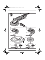
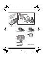
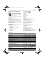
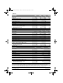
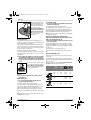
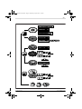
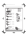
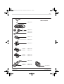
OBJ_DOKU-14244-007.fm Page 1 Wednesday, April 9, 2014 1:51 PM Robert Bosch GmbH Power Tools Division 70745 Leinfelden-Echterdingen Germany www.bosch-pt.com 1 609 92A 0ML (2014.04) O / 98 XXX GWS Professional 20-230 H | 22-180 H | 22-230 H | 22-230 JH | 24-180 H | 24-230 H | 24-230 JH | 24-230 JVX | 26-180 H | 26-230 B | 26-230 H en fr tr ru uk kk ar fa Original instructions Notice originale Orijinal işletme talimatı Оригинальное руководство по эксплуатации Оригінальна інструкція з експлуатації Пайдалану нұсқаулығының түпнұсқасы ςТЎϩХʉ ЌТϾϦφЍʉ ʌμВТЎϺυ ΖЎϩʉ ˒μВЖЙʉʓ ИͳϞφЁʑ OBJ_DOKU-14249-007.fm Page 4 Wednesday, April 9, 2014 1:52 PM 4| 5| 20 19 18 2 1 3 7 9 5 3 4 21 22 23 22 5 24 12 12 5 13 17 5 11 14 25 15 6 10 7 7 9 7 8 8 16 9 8 1 609 92A 0ML | (9.4.14) 26 Bosch Power Tools 1 609 92A 0ML | (9.4.14) GWS 20-230 H GWS 22-180 H GWS 22-230 H/JH GWS 24-180 H GWS 24-230 H/JH GWS 26-180 H GWS 26-230 B/H Bosch Power Tools OBJ_BUCH-827-007.book Page 6 Wednesday, April 9, 2014 1:53 PM 6| 27 1 2 3 28 32 29 30 29 30 31 31 5 5 11 6 10 7 8 1 609 92A 0ML | (9.4.14) 9 7 9 8 Bosch Power Tools OBJ_BUCH-827-007.book Page 7 Wednesday, April 9, 2014 1:53 PM |7 20 19 18 3 7 9 5 4 12 12 17 14 15 16 8 Bosch Power Tools GWS 24-230 JVX 1 609 92A 0ML | (9.4.14) OBJ_BUCH-827-007.book Page 8 Wednesday, April 9, 2014 1:53 PM 8 | English English Safety Notes General Power Tool Safety Warnings Read all safety warnings and all instructions. Failure to follow the warnings and instructions may result in electric shock, fire and/or serious injury. Save all warnings and instructions for future reference. The term “power tool” in the warnings refers to your mainsoperated (corded) power tool or battery-operated (cordless) power tool. WARNING Work area safety Keep work area clean and well lit. Cluttered or dark areas invite accidents. Do not operate power tools in explosive atmospheres, such as in the presence of flammable liquids, gases or dust. Power tools create sparks which may ignite the dust or fumes. Keep children and bystanders away while operating a power tool. Distractions can cause you to lose control. Electrical safety Power tool plugs must match the outlet. Never modify the plug in any way. Do not use any adapter plugs with earthed (grounded) power tools. Unmodified plugs and matching outlets will reduce risk of electric shock. Avoid body contact with earthed or grounded surfaces, such as pipes, radiators, ranges and refrigerators. There is an increased risk of electric shock if your body is earthed or grounded. Do not expose power tools to rain or wet conditions. Water entering a power tool will increase the risk of electric shock. Do not abuse the cord. Never use the cord for carrying, pulling or unplugging the power tool. Keep cord away from heat, oil, sharp edges and moving parts. Damaged or entangled cords increase the risk of electric shock. When operating a power tool outdoors, use an extension cord suitable for outdoor use. Use of a cord suitable for outdoor use reduces the risk of electric shock. If operating a power tool in a damp location is unavoidable, use a residual current device (RCD) protected supply. Use of an RCD reduces the risk of electric shock. Personal safety Stay alert, watch what you are doing and use common sense when operating a power tool. Do not use a power tool while you are tired or under the influence of drugs, alcohol or medication. A moment of inattention while operating power tools may result in serious personal injury. Use personal protective equipment. Always wear eye protection. Protective equipment such as dust mask, non-skid safety shoes, hard hat, or hearing protection used for appropriate conditions will reduce personal injuries. 1 609 92A 0ML | (9.4.14) Prevent unintentional starting. Ensure the switch is in the off-position before connecting to power source and/or battery pack, picking up or carrying the tool. Carrying power tools with your finger on the switch or energising power tools that have the switch on invites accidents. Remove any adjusting key or wrench before turning the power tool on. A wrench or a key left attached to a rotating part of the power tool may result in personal injury. Do not overreach. Keep proper footing and balance at all times. This enables better control of the power tool in unexpected situations. Dress properly. Do not wear loose clothing or jewellery. Keep your hair, clothing and gloves away from moving parts. Loose clothes, jewellery or long hair can be caught in moving parts. If devices are provided for the connection of dust extraction and collection facilities, ensure these are connected and properly used. Use of dust collection can reduce dust-related hazards. Power tool use and care Do not force the power tool. Use the correct power tool for your application. The correct power tool will do the job better and safer at the rate for which it was designed. Do not use the power tool if the switch does not turn it on and off. Any power tool that cannot be controlled with the switch is dangerous and must be repaired. Disconnect the plug from the power source and/or the battery pack from the power tool before making any adjustments, changing accessories, or storing power tools. Such preventive safety measures reduce the risk of starting the power tool accidentally. Store idle power tools out of the reach of children and do not allow persons unfamiliar with the power tool or these instructions to operate the power tool. Power tools are dangerous in the hands of untrained users. Maintain power tools. Check for misalignment or binding of moving parts, breakage of parts and any other condition that may affect the power tool’s operation. If damaged, have the power tool repaired before use. Many accidents are caused by poorly maintained power tools. Keep cutting tools sharp and clean. Properly maintained cutting tools with sharp cutting edges are less likely to bind and are easier to control. Use the power tool, accessories and tool bits etc. in accordance with these instructions, taking into account the working conditions and the work to be performed. Use of the power tool for operations different from those intended could result in a hazardous situation. Service Have your power tool serviced by a qualified repair person using only identical replacement parts. This will ensure that the safety of the power tool is maintained. Bosch Power Tools OBJ_BUCH-827-007.book Page 9 Wednesday, April 9, 2014 1:53 PM English | 9 Safety Warnings for Angle Grinder Safety Warnings common for Grinding, Sanding, Wire Brushing or Abrasive Cutting Off Operations This power tool is intended to function as a grinder, sander, wire brush or cut-off tool. Read all safety warnings, instructions, illustrations and specifications provided with this power tool. Failure to follow all instructions listed below may result in electric shock, fire and/or serious injury. Operations such as polishing are not recommended to be performed with this power tool. Operations for which the power tool was not designed may create a hazard and cause personal injury. Do not use accessories which are not specifically designed and recommended by the tool manufacturer. Just because the accessory can be attached to your power tool, it does not assure safe operation. The rated speed of the accessory must be at least equal to the maximum speed marked on the power tool. Accessories running faster than their rated speed can break and fly apart. The outside diameter and the thickness of your accessory must be within the capacity rating of your power tool. Incorrectly sized accessories cannot be adequately guarded or controlled. Threaded mounting of accessories must match the grinder spindle thread. For accessories mounted by flanges, the arbour hole of the accessory must fit the locating diameter of the flange. Accessories that do not match the mounting hardware of the power tool will run out of balance, vibrate excessively and may cause loss of control. Do not use a damaged accessory. Before each use inspect the accessory such as abrasive wheels for chips and cracks, backing pad for cracks, tear or excess wear, wire brush for loose or cracked wires. If power tool or accessory is dropped, inspect for damage or install an undamaged accessory. After inspecting and installing an accessory, position yourself and bystanders away from the plane of the rotating accessory and run the power tool at maximum no-load speed for one minute. Damaged accessories will normally break apart during this test time. Wear personal protective equipment. Depending on application, use face shield, safety goggles or safety glasses. As appropriate, wear dust mask, hearing protectors, gloves and shop apron capable of stopping small abrasive or workpiece fragments. The eye protection must be capable of stopping flying debris generated by various operations. The dust mask or respirator must be capable of filtrating particles generated by your operation. Prolonged exposure to high intensity noise may cause hearing loss. Keep bystanders a safe distance away from work area. Anyone entering the work area must wear personal protective equipment. Fragments of workpiece or of a broken accessory may fly away and cause injury beyond immediate area of operation. Bosch Power Tools Hold the power tool by insulated gripping surfaces only, when performing an operation where the cutting accessory may contact hidden wiring or its own cord. Cutting accessory contacting a “live” wire may make exposed metal parts of the power tool “live” and could give the operator an electric shock. Position the cord clear of the spinning accessory. If you lose control, the cord may be cut or snagged and your hand or arm may be pulled into the spinning wheel. Never lay the power tool down until the accessory has come to a complete stop. The spinning wheel may grab the surface and pull the power tool out of your control. Do not run the power tool while carrying it at your side. Accidental contact with the spinning accessory could snag your clothing, pulling the accessory into your body. Regularly clean the power tool’s air vents. The motor’s fan will draw the dust inside the housing and excessive accumulation of powdered metal may cause electrical hazards. Do not operate the power tool near flammable materials. Sparks could ignite these materials. Do not use accessories that require liquid coolants. Using water or other liquid coolants may result in electrocution or shock. Kickback and related warnings Kickback is a sudden reaction to a pinched or snagged rotating wheel, backing pad, brush or any other accessory. Pinching or snagging causes rapid stalling of the rotating accessory which in turn causes the uncontrolled power tool to be forced in the direction opposite of the accessory’s rotation at the point of the binding. For example, if an abrasive wheel is snagged or pinched by the workpiece, the edge of the wheel that is entering into the pinch point can dig into the surface of the material causing the wheel to climb out or kick out. The wheel may either jump toward or away from the operator, depending on direction of the wheel’s movement at the point of pinching. Abrasive wheels may also break under these conditions. Kickback is the result of power tool misuse and/or incorrect operating procedures or conditions and can be avoided by taking proper precautions as given below. Maintain a firm grip on the power tool and position your body and arm to allow you to resist kickback forces. Always use auxiliary handle, if provided, for maximum control over kickback or torque reaction during start-up. The operator can control torque reactions or kickback forces, if proper precautions are taken. Never place your hand near the rotating accessory. Accessory may kickback over your hand. Do not position your body in the area where power tool will move if kickback occurs. Kickback will propel the tool in direction opposite to the wheel’s movement at the point of snagging. Use special care when working corners, sharp edges, etc. Avoid bouncing and snagging the accessory. Corners, sharp edges or bouncing have a tendency to snag the rotating accessory and cause loss of control or kickback. 1 609 92A 0ML | (9.4.14) OBJ_BUCH-827-007.book Page 10 Wednesday, April 9, 2014 1:53 PM 10 | English Do not attach a saw chain woodcarving blade or toothed saw blade. Such blades create frequent kickback and loss of control. Safety warnings specific for Grinding and Abrasive Cutting-Off operations Use only wheel types that are recommended for your power tool and the specific guard designed for the selected wheel. Wheels for which the power tool was not designed cannot be adequately guarded and are unsafe. The grinding surface of the centre depressed wheels must be mounted below the plane of the guard lip. An improperly mounted wheel that projects through the plane of the guard lip cannot be adequately protected. The guard must be securely attached to the power tool and positioned for maximum safety, so the least amount of wheel is exposed towards the operator. The guard helps to protect operator from broken wheel fragments, accidental contact with wheel and sparks that could ignite clothing. Wheels must be used only for recommended applications. For example: do not grind with the side of the cut-off wheel. Abrasive cut-off wheels are intended for peripheral grinding; side forces applied to these wheels may cause them to shatter. Always use undamaged wheel flanges that are of correct size and shape for your selected wheel. Proper wheel flanges support the wheel thus reducing the possibility of wheel breakage. Flanges for cut-off wheels may be different from grinding wheel flanges. Do not use worn down reinforced wheels from larger power tools. Wheels intended for larger power tools are not suitable for the higher speed of a smaller tool and may burst. Additional safety warnings specific for abrasive cutting off operations Do not “jam” the cut-off wheel or apply excessive pressure. Do not attempt to make an excessive depth of cut. Overstressing the wheel increases the loading and susceptibility to twisting or binding of the wheel in the cut and the possibility of kickback or wheel breakage. Do not position your body in line with and behind the rotating wheel. When the wheel, at the point of operation, is moving away from your body, the possible kickback may propel the spinning wheel and the power tool directly at you. When wheel is binding or when interrupting a cut for any reason, switch off the power tool and hold the power tool motionless until the wheel comes to a complete stop. Never attempt to remove the cut-off wheel from the cut while the wheel is in motion otherwise kickback may occur. Investigate and take corrective action to eliminate the cause of wheel binding. Do not restart the cutting operation in the workpiece. Let the wheel reach full speed and carefully re-enter the cut. The wheel may bind, walk up or kickback if the power tool is restarted in the workpiece. 1 609 92A 0ML | (9.4.14) Support panels or any oversized workpiece to minimize the risk of wheel pinching and kickback. Large workpieces tend to sag under their own weight. Supports must be placed under the workpiece near the line of cut and near the edge of the workpiece on both sides of the wheel. Use extra caution when making a “pocket cut” into existing walls or other blind areas. The protruding wheel may cut gas or water pipes, electrical wiring or objects that can cause kickback. Safety warnings specific for sanding operations Do not use excessively oversized sanding disc paper. Follow manufacturers recommendations, when selecting sanding paper. Larger sanding paper extending beyond the sanding pad presents a laceration hazard and may cause snagging, tearing of the disc, or kickback. Safety warnings specific for wire brushing operations Be aware that wire bristles are thrown by the brush even during ordinary operation. Do not overstress the wires by applying excessive load to the brush. The wire bristles can easily penetrate light clothing and/or skin. If the use of a guard is recommended for wire brushing, do not allow any interference of the wire wheel or brush with the guard. Wire wheel or brush may expand in diameter due to work load and centrifugal forces. Additional safety warnings Wear safety goggles. Use suitable detectors to determine if utility lines are hidden in the work area or call the local utility company for assistance. Contact with electric lines can lead to fire and electric shock. Damaging a gas line can lead to explosion. Penetrating a water line causes property damage or may cause an electric shock. Release the On/Off switch and set it to the off position when the power supply is interrupted, e. g., in case of a power failure or when the mains plug is pulled. This prevents uncontrolled restarting. Do not touch grinding and cutting discs before they have cooled down. The discs can become very hot while working. Secure the workpiece. A workpiece clamped with clamping devices or in a vice is held more secure than by hand. Products sold in GB only: Your product is fitted with a BS 1363/A approved electric plug with internal fuse (ASTA approved to BS 1362). If the plug is not suitable for your socket outlets, it should be cut off and an appropriate plug fitted in its place by an authorised customer service agent. The replacement plug should have the same fuse rating as the original plug. The severed plug must be disposed of to avoid a possible shock hazard and should never be inserted into a mains socket elsewhere. Products sold in AUS and NZ only: Use a residual current device (RCD) with a rated residual current of 30 mA or less. Bosch Power Tools OBJ_BUCH-827-007.book Page 11 Wednesday, April 9, 2014 1:53 PM English | 11 Product Description and Specifications Read all safety warnings and all instructions. Failure to follow the warnings and instructions may result in electric shock, fire and/or serious injury. While reading the operating instructions, unfold the graphics page for the machine and leave it open. Intended Use The machine is intended for cutting, roughing and brushing of metal and stone materials without the use of water. For cutting with bonded abrasives, a special cutting guard (accessory) must be used. When cutting in stone, provide for sufficient dust extraction. With approved sanding tools, the machine can be used for sanding with sanding discs. Product Features The numbering of the product features refers to the illustration of the machine on the graphics page. 1 Spindle lock button 2 On/Off switch 3 Auxiliary handle (insulated gripping surface) 4 Grinder spindle 5 Mounting flange with O-ring 6 Grinding wheel* 7 Clamping nut 8 9 10 11 12 13 14 15 16 17 18 19 20 21 22 23 24 25 26 27 28 29 30 31 32 Two-pin spanner for clamping nut* Quick-clamping nut * Carbide grinding head* Cutting disc* Hand guard* Spacer discs* Rubber sanding plate* Sanding sheet* Round nut* Cup brush* Cutting guide with dust extraction protection guard * Diamond cutting disc* Handle (insulated gripping surface) Protection guard for grinding (clamping screw) Locking screw for protection guard Protection guard for cutting (clamping screw)* Protection guard for grinding cup* Grinding cup* Two-pin spanner, offset, for grinding cup* Vibration damper Protection guard for grinding Encoding key Clamping lever for protection guard Screw for adjustment of protection guard Protection guard for cutting *Accessories shown or described are not part of the standard delivery scope of the product. A complete overview of accessories can be found in our accessories program. Technical Data Angle Grinder Article number Rated power input Output power Rated speed Grinding disc diameter, max. Thread of grinder spindle Thread length (max.) of grinder spindle Reduced starting current Rotatable main handle Run-on Brake Weight according to EPTA-Procedure 01/2003 – with vibration-damping auxiliary handle – with standard-auxiliary handle Protection class Angle Grinder Article number Rated power input Output power Bosch Power Tools GWS ... 3 601 ... W W min-1 mm mm kg kg GWS ... 3 601 ... W W 22-180 H H81 1.. 2200 1500 8500 180 M 14 25 – – – 22-230 H H82 1.. 2200 1500 6500 230 M 14 25 – – – 22-230 JH H82 2.. 2200 1500 6500 230 M 14 25 – – 24-180 H H83 1.. 2400 1600 8500 180 M 14 25 – – – 5.1 5.0 /II 5.1 5.0 /II 5.3 5.2 /II 5.0 4.9 /II 24-230 H H84 1.. 2400 1600 24-230 JH H84 2.. 2400 1600 26-180 H H55 1.. 2600 1700 1 609 92A 0ML | (9.4.14) OBJ_BUCH-827-007.book Page 12 Wednesday, April 9, 2014 1:53 PM 12 | English Angle Grinder Rated speed Grinding disc diameter, max. Thread of grinder spindle Thread length (max.) of grinder spindle Reduced starting current Rotatable main handle Run-on Brake Weight according to EPTA-Procedure 01/2003 – with vibration-damping auxiliary handle – with standard-auxiliary handle Protection class Angle Grinder Article number Rated power input Output power Rated speed Grinding disc diameter, max. Thread of grinder spindle Thread length (max.) of grinder spindle Reduced starting current Rotatable main handle Run-on Brake Weight according to EPTA-Procedure 01/2003 – with vibration-damping auxiliary handle – with standard-auxiliary handle Protection class Angle Grinder Article number Rated power input Output power Rated speed Grinding disc diameter, max. Thread of grinder spindle Thread length (max.) of grinder spindle Reduced starting current Rotatable main handle Run-on Brake Weight according to EPTA-Procedure 01/2003 – with vibration-damping auxiliary handle – with standard-auxiliary handle Protection class GWS ... 24-230 H 6500 230 M 14 25 – – – 24-230 JH 6500 230 M 14 25 – – 26-180 H 8500 180 M 14 25 – – – kg kg 5.2 5.1 /II 5.3 5.2 /II 6.0 5.9 /II GWS ... 26-230 B H56 3.. 2600 1700 6500 230 M 14 25 – – 26-230 H H56 1.. 2600 1700 6500 230 M 14 25 – – – 26-230 H H56 L.. 2600 1700 6500 230 M 14 25 – – – 6.2 6.1 /II 6.1 6.0 /II 6.1 6.0 /II min-1 mm mm 3 601 ... W W min-1 mm mm kg kg GWS ... 3 601 ... W W min-1 mm mm kg kg 20-230 H H50 1.. 2000 1250 6600 230 M 14 25 – – – 24-230 JVX H64 5.. 2400 1600 6500 230 M 14 18 5.2 5.1 /II 6.5 6.4 /II The values given are valid for a nominal voltage [U] of 230 V. For different voltages and models for specific countries, these values can vary. Only for power tools without reduced starting current: Starting cycles generate brief voltage drops. Interference with other equipment/machines may occur in case of unfavourable mains system conditions. Malfunctions are not to be expected for system impedances below 0.25 ohm. 1 609 92A 0ML | (9.4.14) Bosch Power Tools OBJ_BUCH-827-007.book Page 13 Wednesday, April 9, 2014 1:53 PM English | 13 Assembly Vibration Damper (GWS 24-230 JVX) Mounting the Protective Devices Before any work on the machine itself, pull the mains plug. Note: After breakage of the grinding disc during operation or damage to the holding fixtures on the protection guard/power tool, the machine must promptly be sent to an after-sales service agent for maintenance. For addresses, see section “After-sales Service and Application Service”. Protection Guard for Grinding (GWS 24-230 JVX) Release the clamping lever 30. Place the protection guard with the encoding key 29 engaging into the groove on the spindle collar until the shoulder of the protection guard is seated against the flange of the power tool, and turn the protection guard to the requested position. Lock the clamping lever 30. Adjust the protection guard in such a manner that sparking is prevented in the direction of the operator. The tightening tension of the clamp from the protection guard can be changed by loosening or tightening the adjustment screw 31. Ensure that the protection guard is tightly seated and check regularly. Note: The encoding keys on the protection guard ensure that only a protection guard that fits the machine type can be mounted. Protection Guard for Grinding (Clamping Screw) (GWS 20-230 H/GWS 22-180 H/GWS 22-230 H/JH/ GWS 24-180 H/GWS 24-230 H/JH/GWS 26-180 H/ GWS 26-230 B/H) Place the protection guard 21 on the spindle collar. Adapt the position of the protection guard to the requirements of the work step and lock the protection guard 21 with the locking screw 22. Adjust the protection guard in such a manner that sparking is prevented in the direction of the operator. Protection Guard for Cutting For cutting with bonded abrasives, always use the protection guard for cutting 23/32. Provide for sufficient dust extraction when cutting stone. The protection guard for cutting 23/32 is mounted in the same manner as the protection guard for grinding. The integrated vibration damper reduces occurring vibrations. Do not continue to use the power tool when the damping element is damaged. Hand Guard For operations with the rubber sanding plate 14 or with the cup brush/wheel brush/flap disc, always mount the hand guard 12. The hand guard 12 is fastened with the auxiliary handle 3. Mounting the Grinding Tools Before any work on the machine itself, pull the mains plug. Do not touch grinding and cutting discs before they have cooled down. The discs can become very hot while working. Clean the grinder spindle 4 and all parts to be mounted. For clamping and loosening the grinding tools, lock the grinder spindle with the spindle lock button 1. Actuate the spindle lock button only when the grinder spindle is at a standstill. Otherwise, the machine may become damaged. Quick-clamping Nut With the quick-clamping nut 9, grinding tools can be mounted without additional tools. The quick-clamping nut 9 may be used only for grinding or cutting discs. Use only a flawless, undamaged quick-clamping nut 9. When screwing on, pay attention that the side of the quick-clamping nut 9 with printing does not face the grinding disc; the arrow must point to the index mark 33. Lock the grinder spindle with the spindle lock button 1. To tighten the quick-clamping 33 nut, firmly turn the grinding disc in clockwise direction. Cutting Guide with Dust Extraction Protection Guard The cutting guide with dust extraction protection guard 18 is mounted in the same manner as the protection guard for grinding. Auxiliary Handle Operate your machine only with the auxiliary handle 3. Screw the auxiliary handle 3 on the right or left of the machine head depending on the working method. Bosch Power Tools 1 609 92A 0ML | (9.4.14) OBJ_BUCH-827-007.book Page 14 Wednesday, April 9, 2014 1:53 PM 14 | English A properly attached, undamaged quick-clamping nut can be loosened by hand when turning the knurled ring in anticlockwise direction. Never loosen a tight quickclamping nut with pliers. Always use the two-pin spanner. Insert the two-pin spanner as shown in the illustration. Grinding/Cutting Disc Pay attention to the dimensions of the grinding tools. The mounting hole diameter must fit the mounting flange without play. Do not use reducers or adapters. When using diamond cutting discs, pay attention that the direction-of-rotation arrow on the diamond cutting disc and the direction of rotation of the machine (see direction-of-rotation arrow on the machine head) agree. See graphics page for the mounting sequence. To fasten the grinding/cutting disc, screw on the clamping nut 7 and tighten with the two-pin spanner; see Section “Quickclamping Nut ”. After mounting the grinding tool and before switching on, check that the grinding tool is correctly mounted and that it can turn freely. Make sure that the grinding tool does not graze against the protection guard or other parts. A plastic part (O-ring) is fitted around the centring collar of mounting flange 5. If the O-ring is missing or damaged, the mounting flange 5 must be replaced before resuming operation. Cup Brush/Disc Brush For operations with the cup brush/wheel brush, always mount the hand guard 12. See graphics page for the mounting sequence. The cup brush/disc brush must be able to be screwed onto the grinder spindle until it rests firmly against the grinder spindle flange at the end of the grinder spindle threads. Tighten the cup brush/disc brush with an open-end spanner. Note: Expect more force to be required to loosen the grinding tool (GWS 24-230 JVX). Grinding Cup (GWS 20-230 H/GWS 22-180 H/ GWS 22-230 H/JH/GWS 24-180 H/GWS 24-230 H/JH/ GWS 26-180 H/GWS 26-230 B/H) When working with the grinding cup, mount the special protection guard 24. The grinding cup 25 should never project further out of the protection guard 24 than necessary for the respective grinding application. Adjust the protection guard 24 accordingly to this dimension. See graphics page for the mounting sequence. Screw on clamping nut 7 and tighten with two-pin spanner 26. Approved Grinding Tools All grinding tools mentioned in these operating instructions can be used. The permissible speed [min-1] or the circumferential speed [m/s] of the grinding tools used must at least match the values given in the table. Therefore, observe the permissible rotational/circumferential speed on the label of the grinding tool. max. [mm] D b d Flap Disc For operations with the flap disc, always mount the hand guard 12. Rubber Sanding Plate For operations with the rubber sanding plate 14, always mount the hand guard 12. See graphics page for the mounting sequence. Before mounting the rubber sanding plate 14, attach the 2 spacer discs 13 to the grinder spindle 4 (GWS 20-230 H/ GWS 22-180 H/GWS 22-230 H/JH/GWS 24-180 H/ GWS 24-230 H/JH/GWS 26-180 H/GWS 26-230 B/H). Screw on the round nut 16 and tighten with the two-pin spanner. Note: Expect more force to be required to loosen the round nut 16 (GWS 24-230 JVX). 1 609 92A 0ML | (9.4.14) D b D [mm] d [min-1] [m/s] 180 230 8 8 22.2 22.2 8500 6500 80 80 180 230 – – 8500 6500 80 80 100 30 M 14 8500 45 d b D Bosch Power Tools OBJ_BUCH-827-007.book Page 15 Wednesday, April 9, 2014 1:53 PM English | 15 Rotating the Main Handle (GWS 24-230 JVX/GWS 26-230 B) Before any work on the machine itself, pull the mains plug. 34 35 ment additives (chromate, wood preservative). Materials containing asbestos may only be worked by specialists. – As far as possible, use a dust extraction system suitable for the material. – Provide for good ventilation of the working place. – It is recommended to wear a P2 filter-class respirator. Observe the relevant regulations in your country for the materials to be worked. Prevent dust accumulation at the workplace. Dusts can easily ignite. Operation Starting Operation The main handle 34 can be rotated with respect to the machine housing toward the left or right in steps of 90°. In this manner, the On/Off switch can be brought into a more convenient position for special working situations, e.g., for cutting operations using the cutting guide with dust extraction protection guard 18 or for left-handed persons. Press the handle unlocking button 35 in the direction of the arrow and at the same time turn the main handle 34 to the requested position until it latches. Rotating the Machine Head (GWS 20-230 H/ GWS 22-180 H/GWS 22-230 H/JH/ GWS 24-180 H/GWS 24-230 H/JH/ GWS 26-180 H/GWS 26-230 B/H) Before any work on the machine itself, pull the mains plug. The machine head can be rotated with respect to the machine housing in 90° steps. In this manner, the On/Off switch can be brought into a more convenient position for special working situations, e. g., for cutting operations using the cutting guide with dust extraction protection guard 18 or for left-handed persons. Completely unscrew the four screws. Rotate the machine head carefully, without removing it from the housing, to the new position. Screw in and tighten the four screws again. Dust/Chip Extraction Dusts from materials such as lead-containing coatings, some wood types, minerals and metal can be harmful to one’s health. Touching or breathing-in the dusts can cause allergic reactions and/or lead to respiratory infections of the user or bystanders. Certain dusts, such as oak or beech dust, are considered as carcinogenic, especially in connection with wood-treatBosch Power Tools Observe correct mains voltage! The voltage of the power source must agree with the voltage specified on the nameplate of the machine. Power tools marked with 230 V can also be operated with 220 V. When operating the machine with power from mobile generators that do not have sufficient reserve capacity or are not equipped with suitable voltage control with starting current amplification, loss of performance or untypical behavior can occur upon switching on. Please observe the suitability of the power generator being used, particularly with regard to the mains voltage and frequency. Switching On and Off To start the power tool, press the On/Off switch 2 forward and then down. To lock-on the pressed On/Off switch 2, push the On/Off switch 2 further forward. To switch off the power tool, release the On/Off switch 2, or when it is locked, briefly press the On/Off switch 2 and then release it. To save energy, only switch the power tool on when using it. Switch Version without Lock-on (country-specific): To start the power tool, press the On/Off switch 2 forward and then down. To switch off the machine, release the On/Off switch 2. Check grinding tools before using. The grinding tool must be mounted properly and be able to move freely. Carry out a test run for at least one minute with no load. Do not use damaged, out-of-centre or vibrating grinding tools. Damaged grinding tools can burst and cause injuries. Run-on Brake (GWS 24-230 JVX) The power tool is equipped with the Bosch Brake System, a patented electromechanical run-on brake. When switching off or when the power supply is interrupted, the machine comes to a complete stop within a few seconds. This means a reduction of the run-on time of approx. 70 % when compared with angle grinders without run-on brake, which allows for the power tool to be placed down sooner. 1 609 92A 0ML | (9.4.14) OBJ_BUCH-827-007.book Page 16 Wednesday, April 9, 2014 1:53 PM 16 | English Note: When the braking effect decreases noticeably, the runon brake has failed. The power tool should be sent immediately to an after-sales service (for addresses, see section “Aftersales Service and Application Service”. Reduced starting current (GWS 22-230 JH/ GWS 24-230 JH/JVX) The electronic reduced starting current limits the power consumption when switching the tool on and enables operation from a 13 ampere fuse. Note: When the machine runs at full speed immediately after switching on, the reduced starting current has failed. The power tool should be sent immediately to an after-sales service (for addresses, see section “After-sales Service and Application Service”, page 17). Working Advice Exercise caution when cutting slots in structural walls; see Section “Information on Structures”. Clamp the workpiece if it does not remain stationary due to its own weight. Do not strain the machine so heavily that it comes to a standstill. After heavily straining the power tool, continue to run it at no-load for several minutes to cool down the accessory. Do not touch grinding and cutting discs before they have cooled down. The discs can become very hot while working. Do not use the power tool with a cut-off stand. Note: When not using for extended periods, pull the mains plug out of the socket outlet. When the mains plug is inserted and mains voltage is given, the power tool, even when switched off, still consumes a low amount of current. Rough Grinding Never use a cutting disc for roughing. The best roughing results are achieved when setting the machine at an angle of 30° to 40°. Move the machine back and forth with moderate pressure. In this manner, the workpiece will not become too hot, does not discolour and no grooves are formed. Flap Disc With the flap disc (accessory), curved surfaces and profiles can be worked. Flap discs have a considerably higher service life, lower noise levels and lower sanding temperatures than conventional sanding sheets. Cutting Metal For cutting with bonded abrasives, always use the protection guard for cutting 23/32. When cutting, work with moderate feed, adapted to the material being cut. Do not exert pressure onto the cutting disc, tilt or oscillate the machine. Do not reduce the speed of running down cutting discs by applying sideward pressure. 1 609 92A 0ML | (9.4.14) The machine must always work in an upgrinding motion. Otherwise, the danger exists of it being pushed uncontrolled out of the cut. When cutting profiles and square bar, it is best to start at the smallest cross section. Cutting Stone Provide for sufficient dust extraction when cutting stone. Wear a dust respirator. The machine may be used only for dry cutting/grinding. For cutting stone, it is best to use a diamond cutting disc. When using the cutting guide with dust extraction protection guard 18, the vacuum cleaner must be approved for vacuuming masonry dust. Suitable vacuum cleaners are available from Bosch. Switch on the machine and place the front part of the cutting guide on the workpiece. Slide the machine with moderate feed, adapted to the material to be worked. For cutting especially hard material, e. g., concrete with high pebble content, the diamond cutting disc can overheat and become damaged as a result. This is clearly indicated by circular sparking, rotating with the diamond cutting disc. In this case, interrupt the cutting process and allow the diamond cutting disc to cool by running the machine for a short time at maximum speed with no load. Noticeably decreasing work progress and circular sparking are indications of a diamond cutting disc that has become dull. Briefly cutting into abrasive material (e. g. lime-sand brick) can resharpen the disc again. Information on Structures Slots in structural walls are subject to the Standard DIN 1053 Part 1, or country-specific regulations. These regulations are to be observed under all circumstances. Before beginning work, consult the responsible structural engineer, architect or the construction supervisor. Bosch Power Tools OBJ_BUCH-827-007.book Page 17 Wednesday, April 9, 2014 1:53 PM English | 17 Maintenance and Service Maintenance and Cleaning Before any work on the machine itself, pull the mains plug. For safe and proper working, always keep the machine and ventilation slots clean. In extreme conditions, always use dust extraction as far as possible. Blow out ventilation slots frequently and install a residual current device (RCD). When working metals, conductive dust can settle in the interior of the power tool. The total insulation of the power tool can be impaired. Please store and handle the accessory(-ies) carefully. If the replacement of the supply cord is necessary, this has to be done by Bosch or an authorized Bosch service agent in order to avoid a safety hazard. After-sales Service and Application Service Our after-sales service responds to your questions concerning maintenance and repair of your product as well as spare parts. Exploded views and information on spare parts can also be found under: www.bosch-pt.com Bosch’s application service team will gladly answer questions concerning our products and their accessories. In all correspondence and spare parts order, please always include the 10-digit article number given on the type plate of the machine. Great Britain Robert Bosch Ltd. (B.S.C.) P.O. Box 98 Broadwater Park North Orbital Road Denham Uxbridge UB 9 5HJ At www.bosch-pt.co.uk you can order spare parts or arrange the collection of a product in need of servicing or repair. Tel. Service: (0844) 7360109 E-Mail: [email protected] Ireland Origo Ltd. Unit 23 Magna Drive Magna Business Park City West Dublin 24 Tel. Service: (01) 4666700 Fax: (01) 4666888 Australia, New Zealand and Pacific Islands Robert Bosch Australia Pty. Ltd. Power Tools Locked Bag 66 Clayton South VIC 3169 Customer Contact Center Inside Australia: Phone: (01300) 307044 Fax: (01300) 307045 Inside New Zealand: Phone: (0800) 543353 Fax: (0800) 428570 Outside AU and NZ: Phone: +61 3 95415555 www.bosch.com.au Republic of South Africa Customer service Hotline: (011) 6519600 Gauteng – BSC Service Centre 35 Roper Street, New Centre Johannesburg Tel.: (011) 4939375 Fax: (011) 4930126 E-Mail: [email protected] KZN – BSC Service Centre Unit E, Almar Centre 143 Crompton Street Pinetown Tel.: (031) 7012120 Fax: (031) 7012446 E-Mail: [email protected] Western Cape – BSC Service Centre Democracy Way, Prosperity Park Milnerton Tel.: (021) 5512577 Fax: (021) 5513223 E-Mail: [email protected] Bosch Headquarters Midrand, Gauteng Tel.: (011) 6519600 Fax: (011) 6519880 E-Mail: [email protected] Disposal The machine, accessories and packaging should be sorted for environmental-friendly recycling. Do not dispose of power tools into household waste! Only for EC countries: According to the European Directive 2012/19/EU for Waste Electrical and Electronic Equipment and its implementation into national right, power tools that are no longer usable must be collected separately and disposed of in an environmentally correct manner. Subject to change without notice. Bosch Power Tools 1 609 92A 0ML | (9.4.14) OBJ_BUCH-827-007.book Page 95 Wednesday, April 9, 2014 1:53 PM | 95 Bosch Power Tools 1 609 92A 0ML | (9.4.14) OBJ_BUCH-827-007.book Page 96 Wednesday, April 9, 2014 1:53 PM 96 | 1 605 703 099 GWS 20-230 H GWS 22-180 H GWS 22-230 H/JH GWS 24-180 H GWS 24-230 H/JH GWS 26-180 H GWS 26-230 B/H 1 603 340 031 1 603 340 040 1 607 950 043 2 602 025 181 1 605 510 181 1 605 703 099 1 601 329 013 1 607 000 247 1 603 340 040 1 607 950 004 Ø 180 mm Ø 230 mm 2 605 510 297 2 605 510 298 Ø 180 mm Ø 230 mm 2 605 510 299 2 605 510 300 1 600 793 007 Ø 180 mm Ø 230 mm 1 609 92A 0ML | (9.4.14) 1 605 510 179 1 605 510 180 2 605 438 197 Bosch Power Tools OBJ_BUCH-827-007.book Page 97 Wednesday, April 9, 2014 1:53 PM | 97 GWS 24-230 JVX 1 600 210 039 1 603 340 031 1 603 340 040 1 607 950 043 2 602 025 181 1 601 329 013 1 607 000 247 Ø 180 mm Ø 230 mm 2 605 510 280 2 605 510 281 Ø 180 mm Ø 230 mm 2 602 025 282 2 602 025 283 1 600 793 007 Ø 180 mm Ø 230 mm Bosch Power Tools 2 602 025 284 2 602 025 285 2 605 438 197 1 609 92A 0ML | (9.4.14)