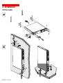
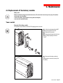
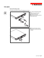
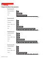
1
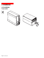
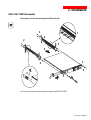
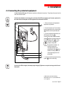
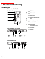
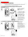
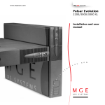
www.mgeups.com
MGE UPS SYSTEMS
Pulsar Evolution
1500 / 1500 Rack
1100 / 1100 Rack
800 / 800 Rack
500 Rack
Installation and user
manual
English
Français
Deutsch
Italiano
Español
Nederlands
Y
O
U
N
O
W
P
O
T
N
O
T
H
I
N
G
W
I
L
L
S
3400711700/AB
www.mgeups.com
MGE UPS SYSTEMS
Pulsar Evolution
1500 / 1500 Rack
1100 / 1100 Rack
800 / 800 Rack
500 Rack
Installation and user
manual
Y
O
U
N
O
W
P
O
T
N
O
T
H
I
N
G
W
I
L
L
S
34007117EN/AB
- Page 1
Page 2 - 34007117EN/AB
Introduction
Thank you for selecting an MGE UPS SYSTEMS product to protect your electrical equipment.
The Pulsar Evolution range has been designed with the utmost care. We recommend that you take the time to read this
manual to take full advantage of the many features of your UPS.
MGE UPS SYSTEMS pays great attention to the environmental impact of its products. Measures that have made Pulsar
Evolution a reference in environmental protection include:
◗ the eco-design approach used in product development,
◗ recycling of Pulsar Evolution at the end of its service life.
To discover the entire range of MGE UPS SYSTEMS products and the options available for the Pulsar Evolution range,
we invite you to visit our web site at www.mgeups.com or contact your MGE UPS SYSTEMS representative.
Important: before installing and using the UPS, always read the safety instructions (document n° 3400722200).
34007117EN/AB
- Page 3
Foreword
Using this document
Information may be found in two ways, using:
◗ the contents;
◗ the index.
Pictograms
Important instructions that must always be followed.
Information, advice, help.
Visual indication.
Action.
Audio indication.
In the illustrations on the following pages, the symbols below are used:
LED off.
LED on.
LED flashing.
Page 4 - 34007117EN/AB
Contents
1.
Presentation
1.1
Overall view ................................................................................................................................. 7
Tower models .................................................................................................................................. 7
Rack models ................................................................................................................................... 7
2.
1.2
Back ............................................................................................................................................. 8
1.3
Control panel ................................................................................................................................. 9
Installation
2.1
Unpacking and parts check ....................................................................................................... 10
Tower models ................................................................................................................................ 10
Rack models ................................................................................................................................. 11
2.2
Installation ................................................................................................................................... 12
Tower models ................................................................................................................................ 12
800/1100/1500 Rack models ........................................................................................................ 13
500 Rack model ............................................................................................................................ 14
3.
2.3
Connecting the protected equipment ....................................................................................... 15
2.4
Connection to the RS232 or USB communications port (optional) ......................................... 16
2.5
Connection to the data-line protection port (optional) ............................................................. 16
2.6
Installation of the communications-card option ...................................................................... 17
Operation
3.1
Start-up ........................................................................................................................................ 18
3.2
Shift to booster or fader mode (during voltage variations in the AC-input power) ..................... 18
3.3
Operation on battery power (following failure of AC-input power) ............................................. 19
Transfer to battery power .............................................................................................................. 19
Threshold for the low-battery warning ........................................................................................... 19
3.4
Personalisation (optional) ........................................................................................................... 20
Function ........................................................................................................................................ 20
ON / OFF conditions tab ............................................................................................................... 20
Battery tab ..................................................................................................................................... 20
Voltage-thresholds tab .................................................................................................................. 21
Sensitivity tab ................................................................................................................................ 21
34007117EN/AB
- Page 5
Contents
4.
Maintenance
4.1
Trouble-shooting ......................................................................................................................... 22
4.2
Replacement of the battery module .......................................................................................... 23
Tower models ................................................................................................................................ 23
Rack models ................................................................................................................................. 25
5.
Environment ..................................................................................................................................... 27
6.
Appendices
6.1
Technical data ............................................................................................................................. 28
Simplified diagram ........................................................................................................................ 26
Technical characteristics ............................................................................................................... 29
Examples of battery backup times ................................................................................................ 30
Page 6 - 34007117EN/AB
6.2
Glossary ....................................................................................................................................... 31
6.3
Index ............................................................................................................................................. 32
1. Presentation
1.1 Overall view
Tower models
Dimensions in mm
(W x H x D)
D
Evolution 800
150 x 237 x 415
Evolution 1100
150 x 237 x 415
Evolution 1500
150 x 237 x 483
Weight in kg
H
AR
LS n
P U lu ti o
Ev o0 0
11
Evolution 800
10.5
Evolution 1100
11.5
Evolution 1500
15
W
Rack models
Dimensions in mm
(W x H x D)
D
H
AR
LS n
P U ut io
Ev ol Rack
1500
Evolution 500 Rack
438 x 43.5 x 353
Evolution 800 Rack
438 x 43.5 x 499
Evolution 1100 Rack
438 x 43.5 x 499
Evolution 1500 Rack
438 x 43.5 x 522
(19") (1U)
Weight in kg
W
Evolution 500 Rack
9
Evolution 800 Rack
15.5
Evolution 1100 Rack
16
Evolution 1500 Rack
19
34007117EN/AB
- Page 7
1. Presentation
1.2 Back
Pulsar Evolution 800 / 1100 / 1500
Pulsar Evolution 1500:
7
4
1
USB communications port.
2
RS232 communications port.
3
Data-line protection.
4
Slot for communications-card option.
5
Outlets for direct connection of
protected equipment.
6
Programmable outlets (1 and 2).
7
Input circuit-breaker.
8
Socket for connection to AC-power
source.
8
5
2
2
6
1
1
3
Pulsar Evolution 500 / 800 / 1100 Rack
1
8
7
5
2
6
3
2
1
4
Pulsar Evolution 1500 Rack
1
4
Page 8 - 34007117EN/AB
8 7 2
1
3
5
2
6
1. Presentation
1.3 Control panel
10 Iluminated ON/OFF button for the outlets.
11 Operation on battery power.
12
UPS fault.
Battery fault.
13 Overload.
14 Group 1 programmable outlets supplied with power.
1
2
15 Group 2 programmable outlets supplied with power.
16 Booster or fader mode.
%
17 Bargraph indicating percent load at output.
%
18 Bargraph indicating the battery charge level.
76 to 100%.
51 to 75%.
26 to 50%.
0 to 25%.
34007117EN/AB
- Page 9
2. Installation
2.1 Unpacking and parts check
Tower models
20
21
22
30
23
AR
LS n
P U lu ti o
Ev o0 0
11
20 Two cords for connection of the protected equipment.
21 RS232 communications cable.
22 USB communications cable.
23 CD-ROM with the Solution-Pac and UPS Driver software.
24 Product documentation.
Page 10 - 34007117EN/AB
24
2. Installation
Rack models
20
23
21
22
25
24
26
AR
L S on
P Uo l u t i ck
Ra
Ev
15 00
20 Two cords for connection of the protected equipment.
21 RS232 communications cable.
22 USB communications cable.
23 CD-ROM with the Solution-Pac and UPS Driver software.
24 Product documentation.
25 Telescopic rails for mounting in 19" bay with mounting hardware.
26 Securing system for equipment power cords.
34007117EN/AB
- Page 11
2. Installation
2.2 Installation
Tower models
AR
LS n
P U lu ti o
Ev o0 0
11
R
An
L St io
P Uo lu0
E v1 0
1
Page 12 - 34007117EN/AB
2. Installation
800/1100/1500 Rack models
Follow steps 1 to 6 for rack mounting of the UPS on the rails.
2
1
6
2
2
4
3
2
5
SAR
P U Lu t i o n
E v o l Rack
1500
6
3
5
The rails and the necessary mounting hardware are supplied by MGE UPS SYSTEMS.
34007117EN/AB
- Page 13
2. Installation
500 Rack model
2
1
SAR
P U Lu t i o n
E v o l Rack
1500
1
3
3
AR
L S ion
P Uo l u t ck
E v 00 Ra
15
AR
L S ion
P Uo l u t ck
E v 00 Ra
15
Page 14 - 34007117EN/AB
2. Installation
2.3 Connecting the protected equipment
A Pulsar Evolution 1500 tower UPS has been used below to illustrate the instructions. The principle is the same for all the
other tower and rack models.
Check that the indications on the rating plate on the back of the UPS correspond to your AC-power system and to
the actual electrical consumption of all the equipment to be connected to the UPS.
8
1 - Remove the power cord supplying the
equipment to be protected.
2 - Connect the power cord (1) just removed
from the equipment to the AC-power socket
␣ ␣ 8 , and then to the AC-power wall outlet.
2
1
6
5
20
3 - Connect the protected equipment to the
UPS using the two cords 20 .
Connect priority loads to the two standard
outlets ␣ 5 and any non-priority loads to the
two programmable outlets ␣ ␣ 6 (1 and 2).
If the UPS is connected to a
computer running MGE
communications software, it is
possible to program the
interruption of power to the
programmable outlets 6 during
operation on battery power, thus
reserving backup power for the
priority loads.
4 - Lock the connections using the securing
system 26 (for rack models only).
As soon as the UPS is energised, the battery begins charging. Eight hours are required to charge to the full rated
backup time.
(1) Make sure the cord has the following
characteristics: 250 V, 10 A, cross-sectional area
1␣ mm2, type HO5.
34007117EN/AB
- Page 15
2. Installation
A Pulsar Evolution 1500 tower UPS has been used below to illustrate the instructions. The principle is the same for all the
other tower and rack models.
2.4 Connection to the RS232 or USB communications port (optional)
21
2
The RS232 and USB
communications ports cannot
operate simultaneously.
1 - Connect the RS232 21 or USB 22
communications cable to the serial port or
the USB port on the computer.
RS232
22
1
2 - Connect the other end of the
communications cable 21 or 22 to the
RS232 2 or USB 1 communications
port on the UPS.
The UPS can now communicate with all
MGE UPS SYSTEMS supervision, set-up or
safety software.
2.5 Connection to the data-line protection port (optional)
The data-line protection function on the UPS
eliminates overvoltages flowing on the
computer-network lines.
Simply connect the line to be protected to
the UPS using the data-line protection
connectors (IN and OUT) as indicated
opposite (RJ45 cables not supplied).
RS232
IN
OUT
DATA LINE
PROTECTION
Page 16 - 34007117EN/AB
2. Installation
2.6 Installation of the communications-card option
4
1 - Remove the slot cover 4 secured by
two screws.
Restricted-access slot for
the communications card
2 - Insert the card in the slot.
3 - Secure the cover with the two screws.
RS232
DATA LINE PROTECTION
IN
OUT
It is not necessary to shut down the UPS to install the communications card.
This operation must be carried out by qualified personnel.
34007117EN/AB
- Page 17
3. Operation
3.1 Start-up
10
11
12
1
2
%
Press the ON / OFF button 10 .
The buzzer beeps and all the LEDs come ON.
The buzzer beeps twice during the self-test, then button 10 remains
ON, indicating that the outlets are supplied with power.
- AC power is present: Only button 10 is ON. The protected
equipment is supplied by the AC-power source.
- AC power is absent: Button 10 and LED 11 are ON. The protected
equipment is supplied by the UPS, operating on battery power.
All the connected equipment is supplied with power.
%
If button 10 or LED 11 are not ON or if LED 12 is ON, there is a fault (see section 4.1).
Note: The battery is charged as soon as the UPS is connected to the AC-power source, even if button 10 is in the OFF
position.
3.2 Shift to booster or fader mode
(during voltage variations in the AC-input power)
1
The booster and fader functions maintain the output voltage supplied by
the UPS within close tolerances around the rated value even if
significant voltage variations occur in the AC-input power. This avoids
calling on battery power.
The values defining the voltage range may be set using the UPS Driver
software.
During operation in booster or fader mode, LED 16 is ON, signalling a
significant voltage variation in the AC-input power.
2
16
%
Page 18 - 34007117EN/AB
%
3. Operation
3.3 Operation on battery power (following failure of AC-input power)
Transfer to battery power
The AC-input power is out of tolerances, LED 11 goes ON.
During operation on battery power, the buzzer beeps every ten seconds.
The equipment connected to the UPS is supplied by the battery.
11
1
2
%
%
Threshold for the low-battery warning
When the threshold is reached, the buzzer beeps every three seconds.
The low-battery warning threshold can be set by the user, with the “UPS
Driver” software.
11
1
%
There is very little remaining battery backup time. Close all
applications because UPS automatic shutdown is imminent.
When the battery reaches the end of its backup time, the UPS shuts
down and all the LEDs go OFF.
2
%
The equipment is no longer supplied with power.
The UPS automatically restarts when power returns.
If the UPS does not restart, check that the “automatic restart when power returns” function has not been disabled (see
section 3.4 Personalisation).
34007117EN/AB
- Page 19
3. Operation
3.4 Personalisation (optional)
Function
Personalisation parameters can be set and modified using the UPS Driver software installed on a computer that is
connected to the UPS (see section 2.4 Connection to the RS232 communications port).
Check that the RS232 21 communications cable is connected.
UPS Driver installation:
1 - Insert the Solution-Pac CD-ROM containing the UPS Driver software in the drive of a PC running Windows.
2 - Open the Windows File manager or Explorer and select the CD-ROM drive.
3 - Double-click "\Emb\Evolutio\Config\upsdriv.exe".
Once UPS Driver has been installed, UPS parameters can be modified in a window containing a number of tabs, each
presenting a set of parameters :
ON / OFF conditions tab
Configurable function
Default setting
Options
Automatic restart
Enabled
Disabled
Cold start
Enabled
Disabled
Forced reboot
Enabled
Disabled
Energy saving
Disabled
Enabled
UPS ON / OFF via software
Enabled
Disabled
Configurable function
Default setting
Options
Interval between automatic battery tests
Once a week
Every day
Once a month
No test
Low-battery warning threshold
20% of the remaining battery
backup time
10 to 40% of the remaining battery
backup time
Protection against deep discharges
Enabled
Disabled
Battery tab
Page 20 - 34007117EN/AB
3. Operation
Voltage-thresholds tab
Configurable function
Default setting
Options
Output voltage on battery power
230 V
200 V - 220 V - 240 V
Upper threshold for transfer to battery power
294 V
271 to 294 V
Fader-mode cut-in threshold
265 V
244 to 265 V
Booster-mode cut-in threshold
184 V
184 to 207 V
Lower threshold for transfer to battery power
160 V
160 to 180 V
Maximum input-voltage range
Disabled
Enabled (1)
Configurable function
Default setting
Options
UPS sensitivity level
Normal
High or low
(1) Lower threshold for transfer to battery power = 150 V
Sensitivity tab
For more informations about these settings, refer to the Help function of the "UPS Driver" software.
34007117EN/AB
- Page 21
4. Maintenance
4.1 Trouble-shooting
Troubleshooting not requiring MGE UPS SYSTEMS after-sales support (all versions)
Indication
Signification
Correction
LED 13 flashes and the
buzzer beeps once.
UPS overload. The power drawn by the connected
equipment exceeds UPS capacity.
Check the power drawn by the
equipment and disconnect any nonpriority devices.
LED 12 flashes.
A battery fault was detected during the automatic
battery test.
Replace the battery module (see
section 4.2).
Troubleshooting requiring MGE UPS SYSTEMS after-sales support
Indication
LED 12 goes ON and
the buzzer sounds
continuously.
Signification
UPS electronics have detected a UPS fault.
◗ The connected equipment is no longer supplied.
The equipment connected to the UPS is no
longer protected.
Page 22 - 34007117EN/AB
Correction
Call the after-sales support
department.
4. Maintenance
4.2 Replacement of the battery module
Safety rules
Batteries constitute a danger (electrical shock, burns). The short-circuit current may be very high. Precautions
must be taken for all handling:
◗ remove all watches, rings, bracelets and any other metal objects;
◗ use tools with insulated handles.
Tower models
Removal of the battery module
This operation may be carried out with the UPS supplying power to the load.
A - Unclip the small plate with the MGE
logo on the front panel of the UPS.
B - Remove the two screws.
C - Remove the left-hand side of the front
panel by pulling it slightly up and then
forward.
C
AR
LS n
P U lu ti o
Ev o0 0
15
B
A
D - Disconnect the battery module by
pulling apart the connectors (never pull on
the cables).
D
34007117EN/AB
- Page 23
4. Maintenance
E - Remove the battery module by pulling
on the plastic tab and proceed with
replacement.
E
Installation of the new battery module
Carry out the above operation in reverse order.
Caution: risk of electric arc when connecting the battery.
To maintain an identical level of performance and safety, use a battery module identical to that previously
mounted in the UPS.
◗ Press the two parts of the battery connector tightly together to ensure proper connection.
◗
◗
Page 24 - 34007117EN/AB
4. Maintenance
Rack models
Removal of the battery module
This operation may be carried out with the UPS supplying power to the load.
A - Unclip the small plate with the MGE
logo on the front panel of the UPS.
B - Remove the two screws.
C - Remove the left-hand side of the front
panel by pulling it forward.
AR
LS
P U ution
Evol0 0
15
C
B
A
D - Disconnect the battery module by
pulling apart the connectors (never pull on
the cables).
D
34007117EN/AB
- Page 25
4. Maintenance
E - Remove the cover.
E
F - Remove the battery module by pulling
on the plastic tab and proceed with
replacement.
F
Installation of the new battery module
Carry out the above operation in reverse order.
Caution: risk of electric arc when connecting the battery.
To maintain an identical level of performance and safety, use a battery module identical to that previously
mounted in the UPS.
◗ Press the two parts of the battery connector tightly together to ensure proper connection.
◗
◗
Page 26 - 34007117EN/AB
5. Environment
This product has been designed to respect the environment:
It does not contain CFCs or HCFCs.
UPS recycling at the end of service life:
MGE UPS SYSTEMS undertakes to recycle, by certified companies and in compliance with all applicable regulations, all
UPS products recovered at the end of their service life (contact your MGE branch office).
Packing:
UPS packing materials must be recycled in compliance with all applicable regulations.
Warning:
This product contains lead-acid batteries. Lead is a dangerous substance for the environment if it is not properly recycled
by specialised companies.
Web site: www.mgeups.com
34007117EN/AB
- Page 27
6. Appendices
6.1 Technical data
Simplified diagram
Filter
Booster / fader transformer
Input
Output
Inverter
Charger
Battery
Page 28 - 34007117EN/AB
6. Appendices
Technical characteristics
Pulsar Evolution
Output rating
AC-input power
◗ Voltage
◗ Frequency
500
800 / 800 rack
1100 / 1100 rack
1500 / 1500 rack
500 VA / 350 W
800 VA / 560 W
1100 VA / 700 W
1500 VA / 1000 W
Single-phase, 160 V to 294 V (1) , 230V nominal.
47 Hz to 70 Hz (50 Hz system) or 56.5 Hz to 70 Hz (2) (60 Hz system)
Output power (operation
on battery power)
◗ Voltage
◗ Frequency
Battery (sealed lead-acid,
maintenance free)
◗ Tower models
◗ Rack models
Environment
Noise level (operation on
AC-input power)
◗ Operating temperature
◗ Relative humidity
(without condensation)
◗
Single-phase, 230 V (3) (+ 6% / - 10%)
50/60 Hz +/- 0.1 Hz
2 x 6 V - 9 Ah,
2 x 12 V - 7.2 Ah,
4 x 6 V - 7.2 Ah
2 x 12 V - 9 Ah,
4 x 6 V - 9 Ah
3 x 12 V - 9 Ah,
6 x 6 V - 9 Ah
<40 dBA
<40 dBA
0 to 35° C
0 to 40° C
20 to 90%
20 to 90%
(1) The upper and lower thresholds may be set using the UPS Driver software.
(2) Or 40 Hz in low-sensitivity mode (may be set using the UPS Driver software).
(3) Adjustable from 200 to 240 V using the UPS Driver software.
34007117EN/AB
- Page 29
6. Appendices
Examples of battery backup times
Pulsar Evolution 500
2 rack-optimized dense servers
1 router
1 hub
0
10
20
30
40
50
60
70
80
90
100
110 120 t (min)
0
10
20
30
40
50
60
70
80
90
100
110 120 t (min)
0
10
20
30
40
50
60
70
80
90
100
110 120 t (min)
0
10
20
30
40
50
60
70
80
90
100
110 120 t (min)
Pulsar Evolution 800
3 rack-optimized dense servers
2 file/print servers
1 data server + 1 hub + 1 router
1 router
1 hub
Pulsar Evolution 1100
3 rack-optimized dense servers
2 file/print servers
1 data server + 1 hub + 1 router
1 router
1 hub
Pulsar Evolution 1500
5 rack-optimized dense servers
3 file/print servers
2 data servers + 1 hub + 1 router
1 router
Page 30 - 34007117EN/AB
6. Appendices
6.2 Glossary
Backup time
Time that the connected equipment can operate on battery power if AC-input power fails.
Bargraph
Device on the front panel indicating the percent remaining backup time or the percent
load.
Booster mode
Automatic UPS operating mode whereby the input-power voltage is increased if it drops
below a value set in the personalisation parameters, thus avoiding a battery discharge.
De-energised
The UPS must be physically disconnected from the AC-input power.
Equipment
Devices and systems connected to the UPS output.
Fader mode
Automatic UPS operating mode whereby the input-power voltage is decreased if it rises
above a value set in the personalisation parameters, thus avoiding a battery discharge.
Input circuit breaker
Circuit breaker protecting the upstream distribution system against UPS faults.
Outlets
Pulsar Evolution has a group of four non-programmable outlets.
Personalisation
The parameters for a number of UPS functions may be modified using the UPS Driver
software to adapt UPS operation to user needs.
Programmable outlets
Pulsar Evolution has two groups of two programmable outlets. They may be used for
sequential start-up of protected equipment, shedding of non-priority loads during
operation on battery power or management of operating priorities to provide the most
critical devices with more backup time before battery power runs out. These outlets may
be programmed using the Solution-Pac software on the CD-ROM supplied with the
UPS.
RS232 communications port
For UPS connection to a computer via the serial port.
Solution-Pac
MGE UPS SYSTEMS safety, set-up and supervision software suite on the CD-ROM
supplied with the UPS.
UPS
Uninterruptible Power Supply.
UPS Driver
Communications software on the CD-ROM supplied with the UPS. It may be used to
personalise the default settings.
USB communications port
For UPS connection to a computer via the USB port.
34007117EN/AB
- Page 31
6. Appendices
6.3 Index
A
M
Automatic start ............................................................... 20
Mode
Booster mode ..................................................... 9, 18
Fader mode ........................................................ 9, 18
Sleep mode (automatic start) ................................. 20
B
Bargraph .......................................................................... 9
Battery
Backup time ............................................................ 30
End of backup time ................................................. 19
Fault ......................................................................... 9
Personalisation ....................................................... 20
Recycling ................................................................ 27
Replacement .............................................. 22, 23, 24
Threshold for low-battery warning .......................... 19
Transfer to battery power ................................... 9, 19
Buttons ............................................................................. 9
Buzzer ............................................................................ 19
C
Circuit breakers
Battery circuit breaker .............................................. 8
Input circuit breaker .................................................. 8
Communication
Cards .................................................................. 8, 17
Ports ................................................................... 8, 16
Connections
Data-line protection ................................................ 16
RS232 communications port .................................. 16
USB communications port ...................................... 16
D
Dimensions ...................................................................... 7
E
Environment ................................................................... 27
F
Fault (UPS) ...................................................................... 9
L
LEDs ................................................................................ 9
Page 32 - 34007117EN/AB
O
Overloads ................................................................... 9, 22
P
Personnalisation ........................................................... 20
Battery .................................................................... 20
ON / OFF conditions .............................................. 20
Output .................................................................... 21
Ports
RS232 ................................................................ 8, 16
USB .................................................................... 8, 16
Programmable outlets .................................................. 8, 9
S
Safety ............................................................................. 23
Start-up .......................................................................... 18
T
Technical characteristics ................................................ 29
Temperature (excessive ambient) .................................. 29
U
UPS Driver .................................................. 18, 19, 20, 29
UPS ON / OFF via software ........................................... 20
W
Web site ........................................................................ 27
Weight .............................................................................. 7
www.mgeups.com
MGE UPS SYSTEMS
Pulsar Evolution
1500 / 1500 Rack
1100 / 1100 Rack
800 / 800 Rack
500 Rack
Installations- und
Bedienungsanleitung
Y
O
U
N
O
W
P
O
T
N
O
T
H
I
N
G
W
I
L
L
S
34007117DE/AB
- Seite 1
Seite 2 - 34007117DE/AB
Einleitung
Wir danken Ihnen, daß Sie sich für ein Produkt von MGE UPS SYSTEMS zur sicheren Stromversorgung Ihrer Systeme
entschieden haben.
Die Baureihe Pulsar Evolution wurde mit größter Sorgfalt entwickelt.
Um die Leistungen Ihrer USV (Unterbrechungsfreien Stromversorgung) optimal nutzen zu können, empfehlen wir Ihnen,
sich ein wenig Zeit zu nehmen und die vorliegende Anleitung aufmerksam zu lesen.
Für MGE UPS SYSTEMS ist Umweltschutz ein wichtiger Aspekt bei der Entwicklung und Herstellung seiner Produkte.
Die ökologische Gesamtkonzeption sowie der konsequente Einsatz der erforderlichen Mittel machen Pulsar Evolution zu
einem beispielhaften Produkt in punkto Umweltfreundlichkeit. Es zeichnet sich besonders aus durch :
◗ den ökologischen Ansatz in allen Phasen der Produktentwicklung,
◗ das Recycling von Pulsar Evolution nach Ablauf der Lebensdauer.
Entdecken Sie das umfassende Angebot von MGE UPS SYSTEMS sowie weitere Optionen zur Baureihe Pulsar
Evolution auf unseren WEB-Sites www.mgeups.com und www.mgeups.de, oder wenden Sie sich persönlich an den
Vertreter von MGE UPS SYSTEMS in Ihrer Nähe.
Achtung: Vor Installation und Inbetriebnahme der USV Sicherheitshinweise lesen! (Anleitung Nr. 3400722200).
34007117DE/AB
- Seite 3
Vorbemerkungen
Aufbau der Installations- und Bedienungsanleitung
Die Suche nach bestimmten Informationen erfolgt auf einfachste Weise:
◗ über das Inhaltsverzeichnis,
◗ über das Stichwortregister.
Bedeutung der Piktogramme
WICHTIG, Hinweise unbedingt befolgen.
Informationen, Ratschläge, Hilfen.
Optische Anzeige.
Maßnahmen, Handlungen.
Akustischer Alarm.
In den Abbildungen der nachfolgenden Seiten sind die LED-Anzeigen mit folgenden Symbolen dargestellt:
LED AUS.
LED AN.
LED blinkt.
Seite 4 - 34007117DE/AB
Inhalt
1.
Ansichten und Beschreibung
1.1
Gesamtansicht ............................................................................................................................ 7
Tower- Modell .................................................................................................................................. 7
Rack- Modell ................................................................................................................................... 7
2.
1.2
Rückansicht ................................................................................................................................. 8
1.3
Anzeige- und Bedienfeld .............................................................................................................. 9
Aufstellung und Installation
2.1
Entfernen der Verpackung und Überprüfung des Lieferumfangs .......................................... 10
Tower- Modell ................................................................................................................................ 10
Rack- Modell ................................................................................................................................. 11
2.2
Aufstellung .................................................................................................................................. 12
Tower- Modell ................................................................................................................................ 12
Rack- Modell 800/1100/1500 ........................................................................................................ 13
Rack- Modell 500 .......................................................................................................................... 14
3.
2.3
Anschluß der Verbraucher ......................................................................................................... 15
2.4
Anschluß des Kommunikationskabels für RS232- bzw. USB-Schnittstelle (wahlweise) ...... 16
2.5
Anschluß der Verbindung für Datenleitungsschutz (wahlweise) ............................................ 16
2.6
Einbau einer Kommunikationskarte (Option) ............................................................................ 17
Betriebszustände
3.1
Inbetriebnahme ........................................................................................................................... 18
3.2
Booster- bzw. Fader-Modus (Ausgleich von Netzspannungsschwankungen) ........................... 18
3.3
Batteriebetrieb (bei Netzausfall) .................................................................................................. 19
Umschaltung auf Batteriebetrieb ................................................................................................... 19
Voralarm "Ende der Autonomiezeit" .............................................................................................. 19
3.4
Kundenspezifische Anpassung per Software (wahlweise) ...................................................... 20
Software, Installation und Funktion ............................................................................................... 20
Registerkarte "Ein/Aus-Bedingungen" .......................................................................................... 20
Registerkarte "Batterie" ................................................................................................................. 20
Registerkarte "Spannungsgrenzwerte" ......................................................................................... 21
Registerkarte "Ansprechempfindlichkeit" ...................................................................................... 21
34007117DE/AB
- Seite 5
Sommaire
4.
Wartung und Service
4.1
Fehlerbehebung .......................................................................................................................... 22
4.2
Austausch des Batteriemoduls ................................................................................................. 23
Tower- Modell ................................................................................................................................ 23
Rack- Modell ................................................................................................................................. 25
5.
Umgebungsbedingungen ........................................................................................................... 27
6.
Anhang
6.1
Technische Daten ....................................................................................................................... 28
Blockschaltbild .............................................................................................................................. 26
Kenndaten ..................................................................................................................................... 29
Beispiele für Batterie-Autonomiezeiten ......................................................................................... 30
Seite 6 - 34007117DE/AB
6.2
Fachbegriffe ................................................................................................................................ 31
6.3
Stichwortregister ........................................................................................................................ 32
1. Ansichten und Beschreibung
1.1 Gesamtansicht
Tower- Modell
Abmessungen in mm
(B x H x T)
T
Evolution 800
150 x 237 x 415
Evolution 1100
150 x 237 x 415
Evolution 1500
150 x 237 x 483
Gewicht in kg
H
AR
LS n
P U lu ti o
Ev o0 0
11
Evolution 800
10,5
Evolution 1100
11,5
Evolution 1500
15
B
Rack- Modell
Abmessungen in mm
(B x H x T)
T
H
AR
LS n
P U ut io
Ev ol Rack
1500
Evolution 500 Rack
438 x 43,5 x 353
Evolution 800 Rack
438 x 43,5 x 499
Evolution 1100 Rack
438 x 43,5 x 499
Evolution 1500 Rack
438 x 43,5 x 522
(19") (1U)
Gewicht in kg
B
Evolution 500 Rack
9
Evolution 800 Rack
15,5
Evolution 1100 Rack
16
Evolution 1500 Rack
19
34007117DE/AB
- Seite 7
1. Ansichten und Beschreibung
1.2 Rückansicht
Pulsar Evolution 800 / 1100 / 1500
Pulsar Evolution 1500 :
7
4
1
USB-Schnittstelle.
2
RS232-Schnittstelle.
3
Datenleitungsschutz.
4
Steckplatz für Kommunikationskarte
(Option).
5
2 normale (nicht programmierbare)
Ausgangssteckdosen.
6
2 programmierbare
Ausgangssteckdosen (1 und 2).
7
Eingangsschalter.
8
Netzanschluß.
8
5
2
2
6
1
1
3
Pulsar Evolution 500 / 800 / 1100 Rack
1
8
7
5
2
6
3
2
1
4
Pulsar Evolution 1500 Rack
1
4
Seite 8 - 34007117DE/AB
8 7 2
1
3
5
2
6
1. Ansichten und Beschreibung
1.3 Anzeige- und Bedienfeld
10 EIN/AUS-Taster (ON/OFF) mit LED zur Freischaltung/Trennung der
Ausgangssteckdosen.
11 Batteriebetrieb.
12
USV-Störung.
Batteriestörung.
13 Überlast.
14 Programmierbare Steckdosengruppe 1 an Spannung.
1
2
15 Programmierbare Steckdosengruppe 2 an Spannung.
16 Booster- oder Fader-Modus.
%
17 Balkenanzeige Auslastungsgrad.
%
18 Balkenanzeige Batterieladezustand.
76 bis 100%.
51 bis 75%.
26 bis 50%.
0 bis 25%.
34007117DE/AB
- Seite 9
2. Aufstellung und Installation
2.1 Entfernen der Verpackung und Überprüfung des Lieferumfangs
Tower- Modell
20
21
22
30
23
AR
LS n
P U lu ti o
Ev o0 0
11
20 2 Verbraucher-Anschlußkabel.
21 RS232-Schnittstellenkabel.
22 USB-Schnittstellenkabel.
23 CD ROM mit USV-Software "Solution Pac" und "UPS Driver".
24 Dokumentation.
Seite 10 - 34007117DE/AB
24
2. Aufstellung und Installation
Rack- Modell
20
23
21
22
25
24
26
AR
L S on
P Uo l u t i ck
Ra
Ev
15 00
20 2 Verbraucher-Anschlußkabel.
21 RS232-Schnittstellenkabel.
22 USB-Schnittstellenkabel.
23 CD ROM mit USV-Software "Solution Pac" und "UPS Driver".
24 Dokumentation.
25 Montagekit für Einbau in 19"-Schränke.
26 Verriegelungsabdeckung für Verbraucher-Anschlußkabel.
34007117DE/AB
- Seite 11
2. Aufstellung und Installation
2.2 Aufstellung
Tower- Modell
AR
LS n
P U lu ti o
Ev o0 0
11
R
An
L St io
P Uo lu0
E v1 0
1
Seite 12 - 34007117DE/AB
2. Aufstellung und Installation
Rack- Modell 800/1100/1500
Montage und Befestigung der Teleskopschienen für Rackeinbau (Schritte 1 bis 6 befolgen)
2
1
6
2
2
4
3
2
5
SAR
P U Lu t i o n
E v o l Rack
1500
6
3
5
Befestigungsschrauben und Teleskopschienen liegen dem Gerät bei.
34007117DE/AB
- Seite 13
2. Aufstellung und Installation
Rack- Modell 500
2
1
SAR
P U Lu t i o n
E v o l Rack
1500
1
3
3
AR
L S ion
P Uo l u t ck
E v 00 Ra
15
AR
L S ion
P Uo l u t ck
E v 00 Ra
15
Seite 14 - 34007117DE/AB
2. Aufstellung und Installation
2.3 Anschluß der Verbraucher
Die nachstehenden Abbildungen zur Illustration der Informationen zeigen das Tower-Modell einer Pulsar Evolution 1500.
Alle Hinweise gelten sinngemäß auch für die übrigen Tower- und Rack-Modelle.
Kenndaten auf dem Typenschild (siehe Geräte-Rückseite) hinsichtlich Übereinstimmung mit den vorhandenen
Netzparametern und der Leistungsaufnahme aller angeschlossenen Verbraucher überprüfen.
1 - Netzkabel der Verbraucher abziehen.
8
2 - Abgezogenes Verbraucher-Netzkabel(1)
in die Gerätesteckdose 8 der USV und
dann in die Netzsteckdose einstecken.
3 - Verbraucher mit Hilfe der Anschlußkabel
␣ 20 an die USV anschließen.
Verbraucher höherer Priorität sollten
vorzugsweise an die beiden Steckdosen 5
und weniger wichtige Verbraucher an die
beiden programmierbaren Steckdosen 6
angeschlossen werden.
Um den Abwurf der Steckdosen 6
im Batterietrieb zu programmieren
und so die Nutzung der
Autonomiereserve zu optimieren,
wird die mitgelieferte USVSoftware benötigt.
2
1
6
5
20
4 - Verriegelungsabdeckung 26 mit Hilfe
der Befestigungsschrauben anbringen (nur
Rack-Modelle).
Nach dem erstmaligen Netzanschluß der USV benötigt das Gerät eine Ladezeit von mindestens 8 Stunden, um die
volle Autonomiezeit der Batterie zur Verfügung zu stellen.
(1) Kenndaten des Anschlußkabels überprüfen
(Mindestens 250 V - 10 A, Querschnitt 1 mm2 Typ
HO5).
34007117DE/AB
- Seite 15
2. Aufstellung und Installation
Die nachstehenden Abbildungen zur Illustration der Informationen zeigen das Tower-Modell einer Pulsar Evolution 1500.
Alle Hinweise gelten sinngemäß auch für die übrigen Tower- und Rack-Modelle.
2.4 Anschluß des Kommunikationskabels für RS232- bzw. USBSchnittstelle (wahlweise)
21
2
RS232- und USB-Schnittstelle
können nicht gleichzeitig
verwendet werden.
1 - RS232- 21 oder USB-Kabel 22 an die
serielle Schnittstelle bzw. den USB-Port des
zu schützenden Systems anschließen.
RS232
22
1
2 - Kabel 21 bzw. 22 mit dem anderen
Ende an die RS232-Schnittstelle 2 oder
den USB-Port 1 der USV anschließen.
Die USV kann nun über verschiedene
Softwarepakete von MGE UPS SYSTEMS
mit dem angeschlossenen Rechnersystem
kommunizieren (Überwachung,
Konfiguration, Sicherheitsparameter).
2.5 Anschluß der Verbindung für Datenleitungsschutz (wahlweise)
Mit Hilfe der USV-Funktion
"Datenleitungsschutz" können
Überspannungen in den Datenleitungen des
EDV-Systems verhindert werden.
Hierzu ist die zu schützende Datenleitung
gemäß nebenstehender Abbildung an die
Steckbuchsen "Data line protection" IN/OUT
anzuschließen (RJ45-Kabel (OUT) nicht im
Lieferumfang).
RS232
IN
OUT
DATA LINE
PROTECTION
Seite 16 - 34007117DE/AB
2. Aufstellung und Installation
2.6 Einbau einer Kommunikationskarte (Option)
4
1 - Abdeckung 4 durch Herausdrehen der
zwei Schrauben von der USV lösen.
Steckplatz für
Kommunikationskarte
(beschränkter Zugang).
2 - Karte in den Steckplatz einstecken.
3 - Karte mit den zwei Schrauben
befestigen.
RS232
DATA LINE PROTECTION
IN
OUT
Die Kommunikationskarten können bei eingeschalteter USV installiert werden.
Der Einbau darf nur durch Fachpersonal erfolgen.
34007117DE/AB
- Seite 17
3. Betriebszustände
3.1 Inbetriebnahme
10
11
12
1
2
%
%
EIN/AUS-Taste 10 drücken.
Der Summer ertönt kurz, und sämtliche LEDs leuchten gleichzeitig auf.
Während des anschließenden Selbstests ertönt der Summer zweimal.
Die LED der Drucktaste 10 leuchtet kontinuierlich und zeigt an, daß die
Ausgangssteckdosen versorgt werden.
- Einspeisenetz vorhanden: Nur die LED der EIN/AUS-Taste 10
leuchtet. Die Verbraucherversorgung erfolgt aus dem Einspeisenetz.
- Einspeisenetz nicht vorhanden: Die LED der EIN/AUS-Taste 10
und die LED 16 leuchten. Die Verbraucherversorgung erfolgt aus der
Batterie über den Wechselrichter der USV.
Alle angeschlossenen Verbraucher werden versorgt.
Bleiben die Anzeigen 10 oder 11 erloschen, oder leuchtet LED 12 auf, liegt eine Störung vor (siehe Abschnitt 4.1).
Hinweis: Die Aufladung der Batterie beginnt sofort nach dem Netzanschluß der USV, selbst wenn die EIN/AUS-Taste 10
noch nicht betätigt wurde.
3.2 Booster- bzw. Fader-Modus
(Ausgleich von Netzspannungsschwankungen)
1
2
16
%
Seite 18 - 34007117DE/AB
%
Die Booster- bzw. Fader-Funktion der USV ermöglicht es, die
Ausgangsspannung innerhalb eines definierten Toleranzbereichs zu
halten. Dabei werden größere Netzspannungsschwankungen ohne
Inanspruchnahme der Batterie durch entsprechendes Anheben bzw.
Absenken der Ausgangsspannung ausgeglichen.
Die Grenzwerte dieses Bereichs können über die USV-Software "UPS
Driver" festgelegt werden.
Während des Betriebs der USV im Booster- bzw. Fader-Modus leuchtet
die LED 16 auf und zeigt eine entsprechende
Netzspannungsabweichung an.
3. Betriebszustände
3.3 Batteriebetrieb (bei Netzausfall)
Umschaltung auf Batteriebetrieb
Verläßt das Einspeisenetz den zulässigen Toleranzbereich, schaltet die
USV auf Batteriebetrieb und die LED 11 leuchtet auf.
Während des Batteriebetriebs ertönt alle 10 Sekunden ein akustisches
Signal.
11
1
Die an die USV angeschlossenen Verbraucher werden
unterbrechungsfrei über die Batterie weiter versorgt.
2
%
%
Voralarm "Ende der Autonomiezeit"
Wird dieser Grenzwert erreicht, ertönt der Summer alle 3 Sekunden.
Dieser Alarmgrenzwert kann über die Software "UPS Driver"
kundenspezifisch angepaßt werden.
11
1
%
Die Batterie ist kurz vor dem Entladeende. Es sollten alle
Anwendungen geschlossen werden, da die Abschaltung der USV
kurz bevorsteht.
2
%
Erreicht die Batterie das Ende ihrer Autonomiezeit, schaltet die USV ab
und alle LEDs erlöschen.
Die Verbraucher werden NICHT mehr versorgt.
Bei Rückkehr des Einspeisenetzes schaltet sich die USV automatisch wieder ein.
Ist dies nicht der Fall, ist zu überprüfen, ob die Funktion "Automatischer Neustart" deaktiviert wurde (siehe Abschnitt 3.4
"Kundenspezifische Anpassung per Software").
34007117DE/AB
- Seite 19
3. Betriebszustände
3.4 Kundenspezifische Anpassung per Software (wahlweise)
Software, Installation und Funktion
Die kundenspezifische Anpassung der USV kann mit Hilfe der Software "UPS Driver" über einen Rechner erfolgen, der
über die serielle RS232-Schnittstelle mit der USV verbunden ist (siehe Abschnitt 2.4).
Vorhandensein der RS232- 21 Verbindung überprüfen.
Installation der Software "UPS Driver":
1. CD-ROM "Solution Pac" in das Laufwerk des PCs (mit Windows-Betriebssystem) einlegen.
2. Windows-Dateimanager bzw. -Explorer öffnen und CD-ROM-Laufwerk auswählen.
3. Doppelklicken auf die Datei Setup.exe im Verzeichnis "\Emb\Evolutio\Config\".
Nach Installation der Software "UPS Driver" stehen folgende Einstellungsmöglichkeiten zur Verfügung:
Registerkarte "Ein/Aus-Bedingungen"
Einstellungen
Default-Einstellung
Kundenspezifische Anpassung
Automatischer Neustart
Aktiviert
Deaktiviert
Kaltstart über Batterie
Aktiviert
Deaktiviert
Zwangsabschaltung
Aktiviert
Deaktiviert
Sleep-Modus
Deaktiviert
Aktiviert
USV-Start/Stop über Software
Aktiviert
Deaktiviert
Einstellungen
Default-Einstellung
Kundenspezifische Anpassung
Zeitintervall für automatischen Batterietest
Einmal pro Woche
Einmal pro Tag
Einmal pro Monat
Kein Test
Grenzwert Voralarm "Ende der Autonomiezeit"
20% Restautonomiezeit
10 bis 40% Restautonomiezeit
Tiefentladungsschutz
Aktiviert
Deaktiviert
Registerkarte "Batterie"
Seite 20 - 34007117DE/AB
3. Betriebszustände
Registerkarte "Spannungsgrenzwerte"
Einstellungen
Default-Einstellung
Kundenspezifische Anpassung
Ausgangsspannung (Batteriebetrieb)
230 V
200 V - 220 V - 240 V
Oberer Spannungsgrenzwert für
Umschaltung auf Batterie
294 V
271 bis 294 V
Grenzwert für Einschaltung des Fader-Modus’
265 V
244 bis 265 V
Grenzwert für Einschaltung des Booster-Modus’
184 V
184 bis 207 V
Unterer Spannungsgrenzwert für
Umschaltung auf Batterie
160 V
160 bis 180 V
Maximaler Eingangsspannungsbereich
Deaktiviert
Aktiviert (1)
(1) Unterer Spannungsgrenzwert für Umschaltung auf Batterie = 150 V
Registerkarte "Ansprechempfindlichkeit"
Einstellungen
Default-Einstellung
Kundenspezifische Anpassung
Ansprechempfindlichkeit der USV
Normal
Hoch oder niedrig
Nähere Informationen zu den Kennwerten können den Hilfetexten der Software "UPS Driver" entnommen werden.
34007117DE/AB
- Seite 21
4. Wartung und Service
4.1 Fehlerbehebung
Fehlerbehebung ohne Inanspruchnahme des MGE-Kundendienstes (alle Modelle)
Fehleranzeige
Fehlerursache
Fehlerbehebung
LED 13 blinkt und
Summer ertönt.
Überlastung der USV. Die Leistungsaufnahme der
angeschlossenen Verbraucher übersteigt die
Nennleistung der USV.
Leistungsaufnahme der
angeschlossenen Systeme
überprüfen und weniger wichtige
Verbraucher abschalten.
LED 12 blinkt.
Es wurde beim Batterietest eine Batteriestörung
festgestellt.
Batterien auswechseln (siehe
Abschnitt 4.2).
Fehlerbehebung, die eine Inanspruchnahme des MGE-Kundendienstes erfordert
Fehleranzeige
LED 12 blinkt und
Summer erzeugt
Dauerton.
Fehlerursache
Es liegt eine interne USV-Störung vor.
◗ Die Versorgung sämtlicher angeschlossenen
Verbraucher ist unterbrochen.
Die an die USV angeschlossenen Systeme
sind nicht mehr geschützt.
Seite 22 - 34007117DE/AB
Fehlerbehebung
Kundendienst benachrichtigen.
4. Wartung und Service
4.2 Austausch des Batteriemoduls
Sicherheitsmaßnahmen:
Die Batterie hat einen hohen Kurzschlußstrom und kann Stromschläge verursachen.
Bei jeder Handhabung der Batterien sind daher folgende Sicherheitsmaßnahmen einzuhalten:
◗ Armbanduhren, Ringe, Armreifen und sonstige an Händen oder Armen getragene Metallgegenstände abnehmen.
◗ Werkzeuge mit Isoliergriff verwenden.
Tower- Modell
Ausbau des Batteriemoduls
Die Batterien können bei eingeschalteter USV ausgetauscht werden.
A - An der Frontseite den Schildträger mit
dem MGE-Logo herausdrücken.
B - Die beiden dahinter liegenden
Schrauben lösen.
C - Linken Teil der Frontabdeckung leicht
anheben nach vorn abziehen.
C
AR
LS n
P U lu ti o
Ev o0 0
15
B
A
D - Batteriemodul durch Lösen der
Steckverbindung (niemals an den
Verbindungskabeln ziehen!) abklemmen.
D
34007117DE/AB
- Seite 23
4. Wartung und Service
E - Batteriemodul durch Greifen der
Kunststofflasche herausziehen und durch
neues ersetzen.
E
Einbau des neuen Batteriemoduls
Die oben beschriebenen Handgriffe in umgekehrter Reihenfolge ausführen.
Achtung! Beim Einschieben der neuen Batterie kann es zur Lichtbogenbildung zwischen den Kontakten
kommen.
◗ Zur Gewährleistung der Sicherheit und des Betriebsverhaltens dürfen nur Austauschmodule verwendet werden,
die mit den eingebauten Batterien baugleich sind.
◗ Es ist sicherzustellen, daß der Batteriestecker vollständig in die zugehörige Steckbuchse eingesteckt ist.
◗
Seite 24 - 34007117DE/AB
4. Maintenance
Rack- Modell
Ausbau des Batteriemoduls
Die Batterien können bei eingeschalteter USV ausgetauscht werden.
A - An der Frontseite den Schildträger mit
dem MGE-Logo herausdrücken.
B - Die beiden dahinter liegenden
Schrauben lösen.
C - Linken Teil der Frontabdeckung nach
vorn abziehen.
AR
LS
P U ution
Evol0 0
15
C
B
A
D - Batteriemodul durch Lösen der
Steckverbindung (niemals an den
Verbindungskabeln ziehen!) abklemmen.
D
34007117DE/AB
- Seite 25
4. Wartung und Service
E - Abdeckung entfernen.
E
F - Batteriemodul durch Greifen der
Kunststofflasche herausziehen und durch
neues ersetzen.
F
Einbau des neuen Batteriemoduls
Die oben beschriebenen Handgriffe in umgekehrter Reihenfolge ausführen.
Achtung! Beim Einschieben der neuen Batterie kann es zur Lichtbogenbildung zwischen den Kontakten
kommen.
◗ Zur Gewährleistung der Sicherheit und des Betriebsverhaltens dürfen nur Austauschmodule verwendet werden,
die mit den eingebauten Batterien baugleich sind.
◗ Es ist sicherzustellen, daß der Batteriestecker vollständig in die zugehörige Steckbuchse eingesteckt ist.
◗
Seite 26 - 34007117DE/AB
5. Umweltschutz
Bei der Entwicklung des vorliegenden Produkts wurde besonders auf seine Umweltverträglichkeit
geachtet:
Es enthält weder FKW- noch FCKW-Verbindungen.
Recycling der USV nach Ablauf der Lebensdauer:
MGE UPS SYSTEMS verpflichtet sich, sämtliche nach Ablauf der Lebensdauer rückgeführten Komponenten durch
zugelassene Entsorgungsunternehmen einer Wiederverwertung gemäß den gesetzlichen Bestimmungen zuzuführen
(wenden Sie sich bitte an Ihre MGE-Vertretung).
Verpackung:
Verpackungsmaterial muß gemäß den gesetzlichen Bestimmungen entsorgt werden.
Hinweis:
Dieses Produkt enthält Bleibatterien. Blei kann die Umwelt schädigen, wenn es nicht gemäß den gesetzlichen Vorschriften
durch Spezialunternehmen entsorgt wird.
Web-Site: www.mgeups.com
34007117DE/AB
- Seite 27
6. Anhang
6.1 Technische Daten
Blockschaltbild
Filter
Booster-/Fader-Trafo
Netz
Verbraucher
Gleichrichter/
Ladegerät
Wechselrichter
Batterie
Seite 28 - 34007117DE/AB
6. Anhang
Kenndaten
Pulsar Evolution
Ausgangsleistung
Einspeisenetz
◗ Spannung
◗ Frequenz
500
800 / 800 Rack
1100 / 1100 Rack
1500 / 1500 Rack
500 VA / 350 W
800 VA / 560 W
1100 VA / 700 W
1500 VA / 1000 W
160 bis 294 V (1), einphasig, Un = 230 V
47 - 70 Hz (50-Hz-Netz) bzw. 56,5 - 70 Hz (2) (60-Hz-Netz)
USV-Ausgang
(Batteriebetrieb)
◗ Spannung
◗ Frequenz
Batterie (wartungsfreie
Bleiakkus)
◗ Tower- Modell
◗ Rack- Modell
Umgebungsbedingungen
Geräuschpegel
(Netzbetrieb)
◗ zul. Betriebstemperatur
◗ relative Luftfeuchtigkeit
(ohne Kondensation)
◗
230 V (3) (+6% / - 10%), einphasig
50/60 Hz +/- 0,1 Hz
2 x 6 V - 9 Ah,
2 x 12 V - 7,2 Ah,
4 x 6 V - 7,2 Ah
2 x 12 V - 9 Ah,
4 x 6 V - 9 Ah
3 x 12 V - 9 Ah,
6 x 6 V - 9 Ah
<40 dBA
<40 dBA
0 bis 35° C
20 bis 90%
0 bis 40° C
20 bis 90%
(1) Oberer und unterer Grenzwert über Software "UPS Driver" einstellbar.
(2) Bis 40 Hz bei niedriger Ansprechempfindlichkeit der USV (einstellbar über USV-Software "UPS Driver").
(3) Einstellbar zwischen 200 und 240 V über USV-Software "UPS Driver".
34007117DE/AB
- Seite 29
6. Anhang
Beispiele für Batterie-Autonomiezeiten
Pulsar Evolution 500
2 optimierte Rack-Server
1 Router
1 Hub
0
10
20
30
40
50
60
70
80
90
100
110 120 t (min)
0
10
20
30
40
50
60
70
80
90
100
110 120 t (min)
0
10
20
30
40
50
60
70
80
90
100
110 120 t (min)
0
10
20
30
40
50
60
70
80
90
100
110 120 t (min)
Pulsar Evolution 800
3 optimierte Rack-Server
2 Print-Server
1 Server + 1 Router + 1 Hub
1 Router
1 Hub
Pulsar Evolution 1100
3 optimierte Rack-Server
2 Print-Server
1 Server + 1 Router + 1 Hub
1 Router
1 Hub
Pulsar Evolution 1500
5 optimierte Rack-Server
3 Print-Server
2 Server + 1 Router + 1 Hub
1 Router
Seite 30 - 34007117DE/AB
6. Anhang
6.2 Fachbegriffe
Ausgangssteckdosen
Pulsar Evolution verfügt abgangsseitig über eine Gruppe von 2 nicht
programmierbaren Ausgangssteckdosen.
Autonomiezeit
Betriebsdauer des Geräts mit Verbraucherversorgung über die Batterie bei Ausfall des
Einspeisenetzes.
Balkenanzeige
LED-Leiste am Bedienfeld zur Anzeige des Auslastungsgrads und der
Restautonomiezeit.
Booster-Modus
Automatische Betriebsart der USV, mit deren Hilfe eine zu geringe Netzspannung ohne
Inanspruchnahme der Batterie um einen einstellbaren Wert angehoben werden kann.
Schalter zum Schutz des Einspeisenetzes gegen Störungen der USV-Anlage.
Eingangsschalter
Fader-Modus
Automatische Betriebsart der USV, mit deren Hilfe eine zu hohe Netzspannung ohne
Inanspruchnahme der Batterie um einen einstellbaren Wert abgesenkt werden kann.
Kundenspezifische
Anpassung
Bestimmte USV-Funktionen können über die Software "UPS Driver" an individuelle
Kundenbedürfnisse angepaßt werden.
Programmierbare
Steckdosen
Pulsar Evolution verfügt abgangsseitig über eine Gruppe von 2 programmierbaren
Ausgangssteckdosen. Sie ermöglichen eine sequentielle Aufschaltung der geschützten
Verbraucher und den Abwurf im Batteriebetrieb, um die Versorgung der kritischsten
Verbraucher am längsten aufrechterhalten zu können. Die Programmierung erfolgt über
die USV-Software "Solution Pac" (mitgelieferte CD-ROM).
RS232-Schnittstelle
Serielle Schnittstelle zur Herstellung einer Kommunikationsverbindung zwischen USV
und geschütztem Rechnersystem.
Solution-Pac
USV-Software zur kundenspezifischen Anpassung von Überwachungs-, Konfigurationsund Sicherheitsparametern. CD-ROM im Lieferumfang der USV-Anlage.
Spannungsfreischaltung
der USV
Physikalische Trennung der USV vom Einspeisenetz.
UPS Driver
Kommunikationssoftware zur kundenspezifischen Anpassung von USV-Einstellungen.
Auf CD-ROM "Solution-Pac" enthalten.
USB-Schnittstelle
Schnittstelle zur Herstellung einer Kommunikationsverbindung zwischen USV und
geschütztem Rechnersystem.
USV
Unterbrechungsfreie Stromversorgung.
34007117DE/AB
- Seite 31
6. Anhang
6.3 Stichwortregister
A
K
Abmessungen und Gewichte ........................................... 7
Alarmton (Summer) ........................................................ 19
Anschlüsse
Datenleitung ........................................................... 16
RS232-Schnittstelle ................................................ 16
USB-Schnittstelle .................................................. 16
Ausschalten der USV über Software ............................. 20
Austausch des Batteriemoduls ......................... 22, 23, 24
Automatischer Neustart ................................................. 20
Kenndaten ...................................................................... 29
Kommunikationskarte ................................................ 8, 17
Kundenspezifische Anpassung ..................................... 20
Ausgang ................................................................. 21
Batterie .................................................................. 20
Ein/Aus-Bedingungen ............................................. 20
B
Balkenanzeige ................................................................. 9
Batterie-Autonomiezeiten ............................................... 30
Batterie
Austausch ..................................................... 22-23-24
Abschaltung am Ende der Autonomiezeit .............. 19
Recycling ................................................................ 27
Störung ..................................................................... 9
Umschaltung auf Batteriebetrieb ........................ 9, 19
Voralarm "Ende der Autonomiezeit" ....................... 19
Booster-Modus ........................................................... 9, 18
D
Drucktasten ...................................................................... 9
L
Leistungsschalter
Batterieschalter ........................................................ 8
Eingangsschalter ...................................................... 8
Leuchtanzeigen ................................................................ 9
P
Programmierbare Steckdosen ..................................... 8, 9
R
RS232-Schnittstelle .................................................. 8, 16
S
Sicherheit ...................................................................... 23
Sleep-Modus .................................................................. 20
Automatischer Neustart .......................................... 20
Störung der USV .............................................................. 9
F
Fader-Modus .............................................................. 9, 18
G
Gewicht ............................................................................ 7
I
Inbetriebnahme .............................................................. 18
U
Überlast ...................................................................... 9, 22
Umgebungstemperatur zu hoch ..................................... 29
Umweltschutz ................................................................. 27
UPS Driver .................................................. 18, 19, 20, 29
USB-Schnittstelle ....................................................... 8, 16
W
Web Site ........................................................................ 27
Seite 32 - 34007117DE/AB