1
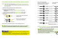
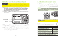
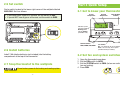
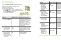
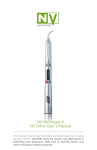
P200 Programmable Thermostat
Installation Instructions & User Guide
For Installation Help
For
1-877-654-9394
1
-877-654-9394
877 654 9394
White-Rodgers.com
White-Rodgers
8100 West Florissant Avenue
St. Louis, MO 63136
© 2011 Printed in China
0037-7260A
Congratulations on the purchase of your White-Rodgers™ thermostat!
Save these instructions for future use!
Questions? Contact White-Rodgers™
customer service at 1-877-654-9394
TABLE OF CONTENTS
• Failure to read and follow all instructions carefully before installing
or operating this control could cause personal injury and/or
property damage.
• The thermostat may stop controlling temperature and your house
may freeze or overheat when batteries are too low. Batteries must
be changed when
or
appears on
the display.
ATTENTION: MERCURY NOTICE
This product does not contain mercury. However, this product may replace a
product that contains mercury. Mercury and products containing mercury must
not be discarded in household trash. Do not touch any spilled mercury. Wearing
non-absorbent gloves, clean up any spilled mercury and place in a sealed
container. For proper disposal of a product containing mercury or a sealed
container of spilled mercury, place it in a suitable shipping container.
Refer to www.White-Rodgers.com for location to send product containing
mercury.
These symbols are used throughout this User Guide.
Watch for them to identify:
Part 1: Before Getting Started ...................................................... Page 2
1.1 Check package contents
1.2 Answer questions about source of heating in your home
1.3 Assemble tools
1.4 Turn off power to your heating and cooling system
Part 2: Remove Old Thermostat and Install New Thermostat .... Page 4
2.1 Expose wires connected to old thermostat
2.2 Label and disconnect the wires
2.3 Install new thermostat’s wallplate
2.4 Match and connect wires
2.5 Set switch
2.6 Install batteries
2.7 Snap thermostat to the wallplate
Part 3: Quick Setup ..................................................................... Page 13
3.1 Get to know your thermostat
3.2 Set fan and system switches
3.3 Select options
3.4 Turn on power to your heating and cooling system
3.5 Set time and date
3.6 Review pre-programmed schedule
Tips
Part 4: Additional Thermostat Features .................................... Page 18
4.1 Customize the pre-programmed schedule
4.2 Set temporary hold at
4.3 Bypass the schedule (permanent hold)
4.4 Set change filter reminder
4.5 Change batteries
4.6 Adjust actual temperature display
Programmable Features
Part 5: Troubleshooting Guide .................................................... Page 24
Cautions
1
1.2 Answer questions about source of
heating in your home
Part 1 Before Getting Started
Before getting started, please review the following
pre-installation checklist.
✔ Do you have either oil or gas burning furnace?
✔ Do you have Hydronic Heating (steam or hot water radiators or
radiant floor heating)?
1.1 Check package contents
Open the package and verify that the following items are included:
1.3 Assemble tools
•
•
•
•
You will need the following tools:
✔ Flat-head screwdriver
✔ 2 AA alkaline batteries
Thermostat wallplate (A) and cover (B)
2 mounting screws and wall anchors (C)
Wire Labels
Installation Instructions and User Guide
A
B
You may also need:
✔ Hammer
✔ Drill with 3/16" (4 mm) bit
✔ Small pliers to bend wires
1.4 Turn off power to your heating and
cooling system
Typically, this is achieved by flipping a switch on the outside of the
furnace/air handler to the “OFF” position.
C
Do not turn the system back on until you have
completed the installation and set up of the thermostat.
If any of the items shown above are missing from your package,
call White-Rodgers™ customer service at 1-877-654-9394 before
returning the thermostat to your place of purchase.
2
3
Part 2 Remove Old Thermostat and
Install New Thermostat
3-Part unit
Do not disconnect wires from the old thermostat until you
label all the wires according to this manual.
Base
Cover
2.1 Expose wires connected to
old thermostat
Wallplate
2-Part unit
C
AUX
G
E
Y
L
W
RC
2.1.1 After turning off power to your heating & cooling system,
expose wallplate with wires and wire terminals. The required
steps vary depending on your old thermostat type.
Your old thermostat may consist of:
• 3 parts: a cover, base and wallplate
or
• 2 parts: a cover and wallplate
4
R
Cover
Wallplate
✔ The Cover: This usually pulls off, but is sometimes secured by a
screw which must be loosened.
✔ The Base: This either pulls off or needs to be removed by loosening
screws under the cover.
✔ The Wallplate: This is removed by loosening the screws that hold
the thermostat to the wall.
5
2.1.2 Loosen all screws holding the old thermostat’s wallplate to
the wall. Do not disconnect the wires from terminals. Allow
the wallplate to hang loosely on the wires.
2.2 Label and disconnect the wires
2.2.1 Note you may see two types of wiring in the old thermostat:
1. Wires leading from the wall to a
terminal on the thermostat
wall
Wall opening
2. Wires connecting one terminal to
another (jumper wire).
These don’t have to be labeled.
Wallplate hanging on the wires
✔ Ignore wire colors. There is no standard color code for
thermostat wires.
✔ Ignore existing wire labels, if they are present.
✔ Use the provided labels to label/re-label the thermostat wires.
✔ The new labels must remain on the wires at least until the
installation process is complete.
✔ No two wires can have the same label.
wall
C
wall
C
6
7
2.2 Label and disconnect the wires (cont.)
2.2.2 Label each wire that comes out of the wall and attaches to
terminals on the old thermostat. Use labels provided with your
new thermostat.
1. Note the letter printed near each wired terminal
2. For each out-of-the-wall wire:
– find its terminal letter(s) in the left column of the table
on page 9,
– label the wire according to the right column of the table.
3. Make the following notes in the right column of the table
on page 9:
wall
– Circle all your out-of-the-wall
labeled wires
C
– Pencil in any jumper wire
connecting 2 terminals
wall
RC
If the OLD thermostat’s
terminal is wired into the wall
and identified by this letter…
wall
G
wall
wall
RC, R
wall
wall
RH, 5, R5
wall
wall
W, 4, W1
wall
Y, Y1
wall
wall
X, C
wall
wall
O
wall
wall
wall
RH
…Then label its wire with
this letter:
G
RC
RH
W
Y
C
O
If terminal “O” is NOT wired. wall
Examples
wall
You’ll need this information further in the installation process!
B
If terminal “O” is wired.
B
wall
C
Note: No thermostat installation uses all of the wires shown
on page 9. In most cases, between 4 and 5 terminals are wired.
Mislabeling the wires could result in damage to your
heating and cooling unit.
Contact White-Rodgers™ Customer Service at 1-877-654-9394 if your
old thermostat contains any wired terminals not listed in the table.
8
2.2.3 After labeling all the wires, use a screwdriver to disconnect
each wire from its terminal. Remove the old thermostat.
Make sure that the wires don’t fall
into the wall after you detach them from
the old thermostat. You may choose to
tape them to the wall or tightly wind them
around a pencil or screwdriver.
9
2.3 Install new thermostat’s wallplate
2.4 Match and connect wires
Do not allow wires to touch each other or parts on
the thermostat. Doing so could result in damage to your heating and
cooling unit.
2.3.1 Detach the new thermostat’s wallplate from the rest of the
thermostat and position the wallplate on the wall according to
the illustration below, passing the labeled wires through the
wire hole in the center of the wallplate.
2.3.2 With the wallplate flush against the wall, mark mounting holes
with a pencil.
2.4.1 Match each wire coming from the wall to its corresponding
terminal, as shown in the illustration below. Insert each wire into
the hole on the side of its matching terminal. Using a screwdriver,
tighten the screw securely. DO NOT REMOVE THE WIRE LABELS.
No thermostat installation uses all of the wires shown below.
In most cases, between 4 and 5 terminals are wired. The remaining
terminals will not be used.
W
RH
Y
O
C
G
B
RC B RH W
RC
C
C G O Y
Mounting hole
ELEC
GAS
Wallplate
2.3.3 Move the wallplate aside. Drill the mounting holes using a 3/16"
drill bit. With a hammer, tap the wall anchors, provided in the
package, into the drilled holes.
2.3.4 Position the wallplate on the wall again and screw the mounting
screws into the wall anchors. Do not use a power screwdriver,
you may damage your thermostat.
G O
W
RH
B
RC
Y
A maximum of one wire from the wall can be wired
into each terminal.
2.4.2 In the new thermostat, a jumper wire
connects the RC and RH terminals.
If, in your OLD thermostat…
Then…
Terminals RC and RH (or 5, or R5)
were connected by a jumper wire,
…leave the jumper wire in place
in the new thermostat.
There was a terminal R, which you then
labeled RC according to 2.2.2,
…leave the jumper wire in place
in the new thermostat.
Terminals RC and RH (or 5 or R5)
were NOT connected by a jumper wire,
…remove the jumper wire from the
new thermostat.
If you’re not sure whether terminals RC and RH were connected in your old
thermostat, refer to your notes made in section 2.2.2.
10
B
11
2.5 Set switch
Part 3 Quick Setup
Find a switch located in the lower right corner of the wallplate labeled
ELEC/GAS. Set it as follows:
RC B RH W
• If you have either a gas or oil furnace, set the switch to GAS.
• If you do NOT have a gas or oil furnace, set the switch to ELEC.
3.1 Get to know your thermostat
Actual
Temperature
Desired
Temperature
Temp Up/Down
Buttons
Indicates system
currently providing
Heating (flame
icon) or Cooling
(snowflake icon)
ELEC
C G O Y
ELEC
GAS
GAS
Control buttons:
TIME, PRGM, RUN, HOLD
2.6 Install batteries
Fan Switch
System Switch
On - fan always on for air circulation Cool - air conditioning
Heat - heating
Auto - fan runs only when system
Off - system turned off
provides Heating or Cooling
Install 2 AA alkaline batteries (not included) into the battery
compartment at the top of the thermostat.
3.2 Set fan and system switches
2.7 Snap thermostat to the wallplate
1. Open the thermostat cover door.
2. Set the FAN switch to AUTO.
3. Set the SYSTEM switch to COOL (to turn on cooling) or HEAT (to
turn on heating).
4. Press RUN.
Do not restore power to the heating and cooling system
until instructed.
12
13
3.3 Select options
Press the PRGM and RUN buttons simultaneously.
You will be prompted to answer 8 “Options”
questions, shown below.
As each option is presented:
buttons to answer each question.
✔ Use the
✔ Use HOLD button to advance to the next question
and the TIME button to return
to the previous question.
Previous
Options
1. Set the temporary
Hold Time (HOLD)
Next
Default Setting Additional Information
0:00
Select desired time, in
15-minute increments, for
the duration of a temporary
override of the current
temperature. If you are not
sure what to chose, 2 hour
setting is usually a good
starting point.
2. Do you want the
Cycle Rate to be
Fast or Slow?
FA
(fast)
3. Do you want the
display light on
(d-L) for a short
time after any key
is pressed?
ON
Select SL (slow) if you have
Hydronic (water or steam)
heating. Otherwise, select
default FA.
Use default ON to
enable backlight
Options
Default Setting Additional Information
4. Do you want
the Energy
Management
Recovery (E)
function to be
enabled?
ON
(enabled)
Select default ON.
Ensures the desired
temperature is reached by
the designated program
schedule time
5. Do you want
to be reminded
when it is time to
change the
air filter? (FLTR)
000
(no reminder)
Select default 000 for now.
To set a filter-change
reminder, see section 4.4
6. Compressor
Lockout (LOC)
OFF
Select ON to provide
protection to your Heating
and Cooling System’s
compressor
7. How much
0HI (no offset)
displayed
temperature offset
do you want?
8. Do you want
temperature
displayed in °C
(Celsius) or °F
(Fahrenheit)?
Select default 0HI for now.
To adjust the actual
temperature reading, see
section 4.6
°F
(Fahrenheit)
When you have answered all 8 questions, press the RUN button.
14
15
3.4 Turn on power to your heating and
cooling system
3.5 Set time and date
3.6 Review pre-programmed schedule
The thermostat is set to control temperature according to the following
pre-programmed, energy-efficient schedule. If this schedule meets
your needs, no further action is required.
Temp
Start Time
Temp
HEAT
Period
Sat - Sun
Start Time
Morning
Day
Evening
Night
6 am
8 am
5 pm
10 pm
70°F
62°F
70°F
62°F
6 am
8 am
5 pm
10 pm
70°F
62°F
70°F
62°F
COOL
Mon - Fri
1. Press the TIME button. The display will show the hour.
– Using the buttons adjust the hour.
2. Press the TIME button. The display will show minutes.
– Using the buttons adjust the minutes.
3. Press the TIME button. The display will show the day of the week.
– Using the buttons adjust the day.
4. Press the RUN button.
Morning
Day
Evening
Night
6 am
8 am
5 pm
10 pm
78°F
85°F
78°F
82°F
6 am
8 am
5 pm
10 pm
78°F
85°F
78°F
82°F
To customize this schedule, continue to the next page (section 4.1).
Congratulations!
You have completed the basic setup of
your new thermostat. It’s ready to use.
To read about additional thermostat features, continue to section 4.
16
17
Part 4 Additional thermostat features
4.1 Customize the pre-programmed
schedule
You can change the day, time period or temperature settings of the
pre-programmed schedule.
1. Set the SYSTEM switch to COOL (to program the cooling schedule),
or to HEAT (to program the heating schedule).
2. Press the PRGM button. The start time and temperature of the first
weekday (Monday through Friday) time period (Morning)
is displayed.
– Use the buttons to set the temperature for that time period.
– Press the TIME button to modify the start time of that time period.
Use the buttons to adjust the start time in 15-minute
increments.
18
3. Press the PRGM button. The start of the next weekday time
period (Day) is displayed. Program Day and then Evening and
Night time periods for weekdays as you programmed Morning.
– Press PRGM after each time period is programmed.
4. Once the weekday periods are set, repeat the programming steps to
program time periods for SA (Saturday) and then SU (Sunday).
5. When you are finished customizing the schedule, press RUN.
4.2 Set temporary hold at
You can override a programmed temperature for a brief period of time.
1. Use the buttons to raise or lower the desired temperature.
2. The override will automatically cancel after a period of time defined
in Setup Question 1 (see Table 3.3 of the manual).
3. Cancel the override by pressing the RUN button.
19
4.3 Bypass the schedule
(permanent hold)
You can manually override the currently-programmed temperature
indefinitely.
4.4 Set change filter reminder
The thermostat can display a reminder when it is time to change the air
filter on your heating and cooling system.
To enable Change Filter reminder:
1. Use the buttons to raise or lower the desired temperature.
2. When the desired temperature is displayed, press the HOLD button.
“HOLD” will be displayed at the bottom of the screen.
3. The override will last until you cancel it.
Cancel the override by pressing the RUN button.
1. Press the PRGM and RUN buttons simultaneously.
2. Press the HOLD button four (4) times until you see FLTR in
the display.
3. Using the buttons select the number of hours until you would like
to be reminded of the filter change. The hours increase in
increments of 50.
4. Press RUN when you are finished.
5. Once the set time has elapsed, FLTR will be displayed on the screen.
6. Reset the reminder by pressing the HOLD and RUN buttons
simultaneously.
20
21
4.5 Change batteries
4.6 Adjust actual temperature display
When the thermostat displays
Your thermostat was accurately calibrated at the factory. However,
if you would like the displayed temperature to read higher or lower than
the actual temperature, you can adjust the displayed temperature
by +/- 4 degrees.
To adjust the actual temperature display:
1. Press the PRGM button and RUN buttons simultaneously.
2. Press the HOLD button to advance through the options until
you reach a screen where “HI” or “LO” is displayed.
3. Use the buttons to adjust the actual temperature; from 4:HI
to 4:LO.
4. Press RUN.
OR
you need to replace batteries with 2 new AA alkaline batteries.
Default setting
– no temperature adjustment
22
23
Part 5 Troubleshooting Guide
5 Troubleshooting Guide (continued)
Problem
Possible Cause
Action
Problem
Possible Cause
Action
Snowflake
icon blinking
5-minute lockout
enabled to protect
compressor
No action needed: should
stop blinking after
5 minutes
No Display or
no backlight
Low Batteries
Replace batteries
No Heat, No Cool,
or No Fan
Blown fuse /
tripped circuit
breaker
Replace fuse or reset
breaker
Thermostat
doesn’t follow the
scheduled program
AM or PM set
incorrectly in the
program
Check the current
settings including AM and
PM designations for
each time period
Furnace power
switch to OFF
Turn switch to ON
Furnace blower
compartment door
or panel loose or
not properly
installed
Replace door panel
in proper position to
engage safety interlock
or door switch
Loose connection
to thermostat
or system
Tighten connections
Low Batteries
Replace batteries
Thermostat &
Indoor
Thermometer
Setting Disagree
The thermometer can be
adjusted +/- 4 degrees.
See Temperature Display
Adjustment in the
Configuration Menu section
24
AM or PM set
incorrectly on the
thermostat’s clock
Heating or Cooling
starts earlier than
programmed
Energy
Management
Recovery function
activated. See
Table 3.3, Step 4
for details
No action required
Reset Operation
If a voltage spike or static discharge blanks out the display or
causes erratic thermostat operation, you can reset the thermostat
by pressing all three buttons (TIME, and both buttons)
simultaneously. This reset will restore your thermostat’s initial
factory setting.
Remember to turn off your heating / cooling
system BEFORE resetting your thermostat. You will then have to
go through a full initial setup described in Part 3 and Part 4 of the
manual before you can turn your Heating & Cooling system back on.
Failure to follow this instruction may lead to your Heating & Cooling
system damage or malfunction.
25