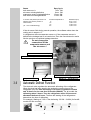
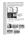
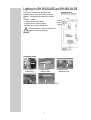
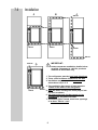
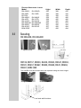
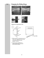
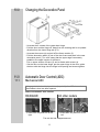
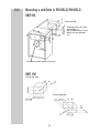
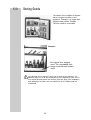
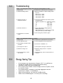
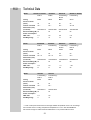
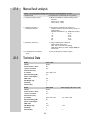
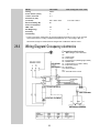
1
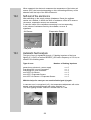
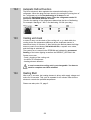
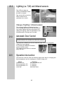
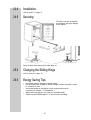
SERVICE INSTRUCTION COOLING 3120 3130 miniBar miniCool Dometic GmbH In der Steinwiese 16 D-57074 Siegen Tel. 0049 / 271/692-0 Fax. 0049 / 271/692-300 Publication-No.: 599 5152 -85 replaces 599 4720-12/5 599 4708-82/3 04.02.25 EN/SERVICE/MB/KV/RS DES ENGLISH Previous models Greenline Face-lifting HiPro TABLE OF CONTENTS 1.0 2.0 Summery of Models Electronics 3 3 2.1 2.2 Fuzzy Logic Fuzzy Logic with 2 Sensors 3 3 3.0 4.0 5.0 Automatic Defrost Function Cooling Unit Heating Shell 4 5 5 5.1 Resistances at Heating Elements 5 6.0 7.0 8.0 9.0 10.0 11.0 Lighting Installation Securing Changing the Sliding Hinge Changing the Decorative Panel Automatic Door Control (ADC) 6 8 9 10 11 11 11.1 11.2 Mechanical ADC Automatic Door Control (electrical) 11 13 17.1 17.2 17.3 Refrigerators without Lighting Refrigerators with Lighting Refrigerators with 55l/56l Capacity 24 25 26 19.1 Temperature in the HiPro compartment Self-test of the electronics Automatic fault analysis Automatic Defrost Function Cooling unit check Heating Shell 27 12.0 13.0 14.0 15.0 16.0 17.0 18.0 19.0 19.2 19.3 19.4 19.5 19.6 20.0 21.0 22.0 23.0 24.0 25.0 26.0 27.0 28.0 29.0 Mounting a miniSafe Storing Goods Troubleshooting Energy Saving Tips Technical Data Wiring Diagrams HiPro Generation HiPro Electronic 18 19 20 20 21 24 27 27 28 28 29 29 29 Lighting 30 Automatic Door Control 30 Operation intervention 30 Installation 31 Securing 31 Changing the Sliding Hinge 31 Energy Saving Tips 31 Manual fault analysis 32 Technical Data 32 Wiring Diagram/ Occupancy electronics 33 2 1.0 Summery of Models Face lifting models and Greenline models are the latest generation of miniBars/miniCools and consumes approximately 40% less energy than its predecessors. Face lifting RH RH RH RH RH RH RH RH RH - 430LD 440LD 441LD 460LD 461LD 456LD/LDE 455LD 436D 447D Greenline Models RH 330LD RH 340LD RH 341LD RH 360LD RH 361LD RH 356LD/LDE RH 355LD RH 136D RH 137D EA 330/L EA 355/L EAW 3220 Previous Models RH RH RH RH RH RH RH - 236LD 237LD 238LD 252LD 255LD 300LD 226LD Changes Face-lifting models to Greenline models: Automatic defrost -cycle and design Changes Greenline models to Previous models: cooling unit, the heating cartridge, lighting, insulation and electronic controls (Fuzzy Logic). 2.0 Electronics 2.1 Fuzzy Logic All Greenline models and Facelifting models maintain a constant temperature level which has been set at the beginning of operation. This temperature level is controlled by electronic intelligence in an energy-saving way. Unlike conventional appliances, the electronic control A component does not switch on and off but controls (clocks) the cooling units heating power in a way which does not require system circulation to be interrupted. The electronic controls sensor (A) is an air sensor. This means that the sensor can react directly to the temperature inside the cooling appliance. 2.2 Fuzzy Logic with 2 sensors By means of the second sensor the electronics carries out a leak detection test. If leaks or blockages in the cooling unit are recognised the miniBar is shut off by the electronics. The test is done after every defrost cycle (every 24 hours). After a Power-On-Reset, the controllers software runs a self test routine to check the function of the sensors. The result of the test is shown with the length of the first duty-cycle of the heating element (jumper X4). There are four different states which are shown in the following table: 3 Status both sensors o.k. air-sensor missing/defective evaporator-sensor missing/defective both sensors missing/defective In service case please pull sensor off electrics and check by means of measurement. (ch. 15.0 Troubleshooting) Duty-Cycle 7 sec. ON 9 sec. ON 12 sec. ON 15 sec. ON Ambient temperature°C 0° 10° 15° 20° Resistance (kW) 32,51 +/-2% 19,86 +/-2% 15,68 +/-2% 12,48 +/-2% If the air-sensor fails during normal operation, the software shuts down the cooling unit in steps to 0. In refrigerators without evaporator-sensor or if the evaporator-sensor is defective the leakage test is not carried out.Then the new electronics works like the previous one without leakage detection. Do not change the connections of the evaporator-sensor and the air-sensor ! Connections air-sensor = Y1, Y2 Connections evaporator-sensor = Y3, Y4 N X4, connection heating element Evaporator-sensor 3.0 Air-sensor X5,X6 = L X1,X2,X3 = N Automatic Defrost Function The electronic also regulates the automatic defrosting of the refrigerator. When the plug has been stuck to the socket the running time of the refrigerator up to the first defrosting is 15 hours for greenline models and 39 hours for the new face lift models (RH4XX). For all models the defrosting takes 2 hours. Then the refrigerator works 22 hours and afterwards defrosts 2 hours. Therfore the starting of the refrigerators determines the time of defrosting. For example: Starting at 7.00h = first defrosting 22.00h - 24.00h (for facelift models 22.00h next day) (39h) T T S 4 T S 4.0 Cooling Unit 5.0 Heating Shell The cooling unit has been optimised for the Greenline models and FaceLifting models. Unlike the cooling units of its predecessors, the Greenline models and Face Lifting models cooling units can be replaced. When replacing the cooling unit, however, the heating element (heating shell) must be replaced as well. Ammonia is used as a coolant. This is a natural compound also used in house hold cleaning agents (1 litre of Salmiak cleaner contains up to 200g of ammonia - about twice as much as is used in the refrigerator). For the safety of hotel guests and personnel, it has been established by inspectors that the coolant poses no threat to health. The conventional heating element (previous models) is replaced by a heating shell. The heating shell is situated directly to the cooker tube. An optimal efficiency ratio is achieved by means of a direct and enlarged contact area. In case service is required: 142 mm Attention please! The heating bowls upper edge must be placed at the shown position (142 mm). Install the mounting clip at the centre of the heating shell. 5.1 Measuring of resistances at heating elements Connections N and X4 Measure resistance... ...replace heating shell if required. 230V / 65 W 230V / 80 W 110V / 65 W 110V / 80 W heating shell heating shell heating shell heating shell W ~ 800W W ~ 650W W ~ 186W W ~ 150W 5 Resistances : ch. 15.0 Troubleshooting 6.0 Lighting (except for RH 356LD/E, RH 456LD/E) All Greenline and face lifting cooling appliances are equipped with sensorcontrolled lighting. The lightings sensor (proximity switch, A) is activated by means of a magnet (B) which has been foam-installed into the door. The lighting mechanism consists of two lamps for 180-250V operation switched in series. For voltages of 100-140V, the lamps are switched in parallel by means of a bridge. 100-140V 180-250V B A A = Proximity switch Take care when replacing- pay attention to correct polarity B = Magnet The proximity switch (A) is mark with a N on the left side in front (correct polarity) . If you chance the proximity switch please eighth of the polarity. A Changing bulbs: 1. Pull out the mains plug. 4. Insert new bulb. 2. Remove the reflector disk. 5. Clip reflector disk back in. 6 3. Remove defective bulb. Lighting for RH 356LD/LDE and RH 456LD/LDE The above models are equipped with separate warm shelf and cooling section lighting. This lighting mechanism consists of: - sensor - switch - 1 light bulb for warm shelf - 2 light bulb for cooling section - Transformer (output voltage 6V) Pay attention to country-specific voltages for the transformer! Changing bulbs: 1. 2. 1. Pull out the mains plug. 2. Remove the reflector disk. 3. Remove the defective bulb. 4. Insert new bulb. 5.Clip reflector disk back in. 7 90° 7.0 Installation 200cm² 200cm² 200cm² 200cm² 20mm 200cm² 20mm 20mm 200cm² IMPORTANT: 200cm² Please follow the installation details below carefully. Guarantee is valid for products installed as described only. 20mm 1. The refrigerator must be level both directions 2. There sould be 20mm clearance to the wall 3. Ventilation must be provided as shown in alternatives A,B,C or D 4. The ventilation duct must at least measure 105mm x the wtdth of the refrigerator 200cm² 5. Only the entire cooling unit must project into the duct as shown 6 Air passing through the duct must not be preheated by any source of heat 7. Ventilation grills, if used, must have openings of at least 200cm² each 8 Recess dimensions in mm: Model RH 430LD, RH 330LD RH 436D, RH 136D EA 330L RH 440LD, RH 340LD RH 447D, RH 137D RH 441LD, RH 341LD RH 456LD/E, RH 356LD/E RH 460LD, RH 360LD RH 461LD, RH 361LD EAW 3220 8.0 Hight 526 526 526 558 558 558 662 567 567 567 Width 388 388 388 405 405 405 454 490 490 490 Depth 432 432 432 466 466 469 523 494 494 494 Securing RH 356LD/E, RH 456LD/E 1. Tighten screw. 2. Put on cap. RH136, RH137, RH330, EA330, RH340, RH341, RH360, RH361, RH437, RH447, RH430, RH440, RH41, RH460, RH461, EAW 3220 The miniBar must be screwed onto the cupboard using the lower hinges. 1. Tighten screw. 2. Put on cap. on level with furniture 9 9.0 Changing the Sliding Hinge 2. 1. 1. 2. 3. 4. Distance to cupboard door (A) 1. mm A 2. mm 1. When closed, the cupboard door (A) must not lie against the rest of the surrounding cupboard area (distance 1-2mm). 2. There must be a distance of 6-8mm between the cupboard door and the miniBar. 10 10.0 Changing the Decorative Panel - Unscrew the 2 screws of the upper door hinge. - Pull the door and the hinge off, away from the housing and in an upward direction from the lower hinge pin (2-3). - Unscrew the screws (4) and pull off the frame section (5). - Pull the decorative panel (6) out of the door frame and push in the new decorative panel (7) in such a way that the upper edge runs exactly parallel to the upper section of the frame. Put on upper section of frame (5) and re-fasten with screws (4). - Set the door on the lower hinge, put the upper hinge in the door, guide the door with the hinge into the hinge hole opening and screw together. 11.0 11.1 Automatic Door Control (ADC) Mechanical ADC Using a red dot in the display window (A, point 3), the ADC shows that the miniBar´s door has been opened. Reset of automatic door control: All other models RH456LD/E 2. 2. A A 1. 3. Insert ADC key and turn to the right. 3. Insert ADC key and turn to the left. The red dot has disappeared now. 11 1. 11.1.1 Change of the Mechanical ADC ( for RH356 / RH456 LD E) Pin (triggers a weight when opening the door ) ADC - component, complete The complete component is not screwed in the doorframe but inserted. So without removal of the door or loosing of screwings the ADC-component can be exchanged. Press in the mounting pins and pull out the component a little bit. Press in the mounting pins on the other side as well by means of a screw driver..... ......and pull out the complete ADC. 12 11.2 Automatic Door Control (electrical) (for RH356 / RH456 LD E) When the miniBar is opened, a magnetically operated approximation switch located underneath on the fridge is activated (FIG 1.) Depending on the connection (opening/closing mechanism), an electric circuit is closed or opened. Accordingly, this is registered and processed at the hotel reception. Note: Electrical rating! The miniBar´s wiring connection is situated at the rear of the appliance and consists of a 3-pin terminal strip (1). 1= Terminal strip 2= Approximination switch A= blue (opening mechanism) B= black (closing mechanism) C= white FIG. 1 11.2.1 Installation of the Electrical Door Control The following miniBars could be retrofitted with an electrical door control : RH 330, RH 340, RH 341, RH 360, RH 361, RH 430, RH 440, RH 441, RH 460, RH 461 with the Service-Kit Spare part number: 210 6821-20 Instruction 599 4722-46/9 RH355, RH356 with the Service-Kit Spare part number: 210 6821-30 Instruction 599 4722-59/2 The instructions are on the following pages. 13 INSTRUCTION Retrofit Electrical Automatic Door Control RH 330, RH340, RH 341, RH 360, RH 361 In order to retrofit the electrical automatic door control, the following service-kit with spare part number 210 6821-20 will be required. You can order the service-kit at: Dometic GmbH Export Department In der Steinwiese 16 D-57074 Siegen Tel.: 0049 271/ 692-0 Fax.: 0049 271/ 629-303 A E D C B Service-kit Spare part number: 210 6821-20 three pieces F Mounting the Electrical Automatic Door Control 1. Pull out the mains plug. 2. Unscrew the door hinge. 3. Remove the door. A 5. Mount the magnet (B) at the lower doorstrip.The magnet should be directed towards the inside of the miniBar. 6. Unscrew the two lower hinges. 7. Take the distanceplates (A) and put the plates under the hinges . 4. Unscrew the middle screw from the lower doorstrip. A 8. Mount the hinges with the distanceplates back on place. 599 4722-38/6 RS 04.03.1999 14 E F 9. Unscrew the two feet. 10. Take two plain washers (F) und put the washers under the feet. Mount the feet back on place. 11. Drill a hole for the sensor, ø3mm, depth 5mm. C 12. Fix the sensor (E) with clip (C), leveled with the housing. 10 mm Ø 3 mm centred D 13,5 mm 13. Mount the terminal strip (D) on the rear side of the miniBar (Prick two holes in the rear wall for mounting the terminal strip). 1= terminal strip 2= approximation switch A= blue (opening mechanism) B= black (closing mechanism) C= white 14. Lead the sensor-cable to the terminal strip and fix the cable with scotch tape. 15. Connect the Sensor-cable to the terminal strip. 16. Take the last plainwasher and put it on the lower hinge pin. 17. Mount the door back on place (follow point 2 and 3 backwards). 15 INSTRUCTION Retrofit Elelectrical Door Control RH 355, RH 356 In order to retrofit the electrical door control for the above model, the following service-kit with spare part number 210 6821-30 will be required. You can order the service-kit at: Electrolux GmbH Export department In der Steinwiese 16 D- 57074 Siegen Tel.: 0049 271/ 692-0 Fax.: 0049 271/ 629-300 A B C D Service-Kit Spare part number: 210 6821-30 If the minibar is wellappointed with 4 feet (8mm high), replace the 4 feet with new feet (11mm high). Spare part number 295 1182-02. Attention! The feet are not contain in the service-kit. Order the 4 feet separately. If the miniBar is wellappointed with feet 11mm or higher, the high for the door control is ok. Mounting the Electrical Door Control miniBar-underside Scotch tape 1. Pull out the mains plug. Position for mouning the sensor (D) with the clamp (B). Position for mounting the magnet. The magnet should be directed towards the inside of the miniBar. 2. Mount the sensor and the magnet. 16 599 4722-62/6 RS 31.03.1999 miniBar - sidewall (inside) C 4. Mount the terminal strip (C). 2 x Ø2,2 drillings for mounting the terminal strip. 5. Connect the sensor-cables to the terminal strip. 1= Terminal strip 2= Approximination switch A= blue (opening mechanism) B= black (closing mechanism) C= white Only for miniBar with feed 8 mm high! 6. Dismantle the 8 mm high feed and mount the feet 11 mm high. 17 12.0 Mounting a miniSafe in RH355LD/ RH455LD SKE160 3 cap nuts M8 Drawing picture for right hand hinge (1). By left hand hinge, 10mm drilling on the opposite (2). 3 mushroom head square neck bolt SKE 180 Fixing rear side Fixing underside 18 13.0 Storing Goods The statics of the miniBars is aligned with the original condition of the appliance. Changes, e.g. bigger door étagères lead to static changes . The door could be overloaded. Example : No original door étagère used. The overloaded door hangs crookedly and doesn't close. Any damage due to improper use is not covered by the warranty. The warranty does not cover any modifications to the appliance or the use of non-original Dometic parts; the warranty does not apply if the installation and operating instructions are not adhered to and no liability shall be entertained. 19 14.0 Troubleshooting Failure : No cooling (the cooling unit at the back of the appliance is cold) Possible Cause Fault Elimination (authorised service provider) a.) Defective heating shell ? a.) Measure resistance, replace heating shell if required. 230V / 65 W ~ 800W 230V / 80 W ~ 650W 110V / 65 W ~ 186W 110V / 80 W ~ 150W b.) Defective Air and / or Evaporator-Sensor? b.) Pull sensor off electrics and check by means of measurement. Ambient Temperature (°C) Resistance (kOhm) 0° 32,51 +/-2% 10° 19,86 +/-2% 15° 15,68 +/-2% 20° 12,48 +/-2% c.) Defective electronic ? c.) Plug in and measure voltage applied at heating shell output! After a maximum of 15 seconds, the heating shell will be driven by mains voltage. d.) The appliance is in defrost mode. d.) Pull out plug and put back in again. Failure : No cooling (the cooling unit is warm) Possible Cause 15.0 Fault Elimination (authorised service provider) a.) Is the appliance level? a.) Level the appliance using a spirit level. b.) Has sufficient ventilation been provided ? b.) See section "Installation 7.0". c.) Running time to short ? c.) Leave system running for a few hours. d.) Defective cooling unit ? d.) Replace cooling unit and - if requiredrefrigerator. e.) Light permanently on when door closed. e.) Replace lighting sensor. Install new door, if required. Energy Saving Tips At an average room temperature of approx. 22°C, it is sufficient to operate the miniBar with an average thermostat setting. If possible, always store pre-cooled goods. Do not expose the miniBar to direct sunlight and do not place it close to a source of heat. An unobstructed air circulation in the fridge aggregate must be ensured (ref. chapter 7.0 Installation). When removing goods, only open the miniBar briefly. Switch on the miniBar approx. 12 hours prior to stocking. 20 16.0 Technical Data Model RH330LD / EA330L Built-in RH340LD RH341LD RH355LD / EA355L Built-in Freestanding / Freestanding Built-in Casing Metal Metal Metal Wood (litres) 30 40 40 55 Cooled / uncooled 30 / - 40 / - 40 / - 35 / 20 522x384x412 554x401x446 554x401x449 780x420x445 65 65 65 Gross Contents Dimensions (mm) (H x W xD) Electrical Rating (W) 65 Power Consumption kWh / 24h* 0,7 0,8 0,8 0,8 Net Weight (kg) 11 14 15 26 Model RH356LDE RH356LD RH360LD RH361LD Built-in Freestanding Freestanding / Freestanding / Built-in Built-in Metal Metal Metal Metal (litres) 56 56 60 60 Cooled / uncooled 40 / 16 40 / 16 60 / - 60 / - 658x450x503 730x450x505 563x486x474 563x486x474 65 80 80 Casing Gross Contents Dimensions (mm) (H x W x D) Electrical Rating (W) 65 Power Consuption kWh / 24h* 0,9 0,9 1,0 1,45 Net Weight (kg) 21 21 20 23 RH136D RH137D Freestanding / Freestanding / Built-in Built-in Metal Metal (litres) 30 40 Cooled / uncooled 30 / - 40 / - 522x384x411 554x401x446 Model Casing Gross Contents Dimensions (mm) (H x W x D) Electrical Rating (W) 65 65 Power Consuption kWh/ 24h* 0,7 0,8 Net Weight (kg) 11 14 * Power consumption measured at an average ambient tempertature of 25°C as an average annual value and at a cooling compartment tempertature of 7°C in line with DIN/EN153. We reserve the right to make technical modifications to our products without notice! 21 Model RH 430LD RH 440LD RH 441LD RH 455LD Built-in Built-in Freestanding / Freestanding Built-in Casing Metal Metal Metal Wood (litres) 30 40 40 55 Cooled / uncooled 30 / - 40 / - 40 / - 35 / 20 522x384x412 554x401x446 554x401x449 780x420x445 65 65 65 Gross Contents Dimensions (mm) (H x W xD) Electrical Rating (W) 65 Power Consumption kWh / 24h* 0,7 0,8 0,8 0,8 Net Weight (kg) 11 14 15 26 Model RH 456LDE RH 456LD RH 460LD RH 461LD EAW3220 Built-in Freestanding Freestanding / Freestanding / Built-in Built-in Metal Metal Metal Metal (litres) 56 56 60 60 Cooled / uncooled 40 / 16 40 / 16 60 / - 60 / - 658x450x503 730x450x505 563x486x474 563x486x474 65 80 80 Casing Gross Contents Dimensions (mm) (H x W x D) Electrical Rating (W) 65 Power Consuption kWh / 24h* 0,9 0,9 1,0 1,45 Net Weight (kg) 21 21 20 23 Model RH 436D RH 447D RH 438D RH 448D Freestanding / Freestanding / Built-in Built-in Built-in Built-in Metal Metal Metal Metal (litres) 30 40 30 40 Cooled / uncooled 30 / - 40 / - 30 / - 40 / - 522x384x411 554x401x446 522x384x412 554x401x446 65 65 65 Casing Gross Contents Dimensions (mm) (H x W x D) Electrical Rating (W) 65 Power Consuption kWh/ 24h* 0,7 0,8 0,7 0,8 Net Weight (kg) 11 14 11 14 * Power consumption measured at an average ambient tempertature of 25°C as an average annual value and at a cooling compartment tempertature of 7°C in line with DIN/EN153. We reserve the right to make technical modifications to our products without notice! 22 Technical Data miniSafe miniSafe Schließsystem SK 160 SKE 160 *SKE 180 *SKE190 Built-in Built-in Built-in Built-in Mechanical, Electronical, Electronical, Electronical, key keycode keycode keycode Gehäuse Steel 2 mm Steel 2 mm Steel 2 mm Steel 2 mm Tür Steel 2 mm Steel 2,5 mm Steel 5 mm Steel 5 mm Volumen (Liter) 6,8 7,0 19 28 167x250x236 160x250x218 210x300x355 240x375x370 Nettogewicht (kg) ca.7 5,5 10,5 13,3 Notöffnung Masterkey and Masterkey and Masterkey and electronical electronical electronical Mastercode Mastercode Mastercode Abmessungen (mm) (H x B xT) Masterkey * socket for charging electronical devices as option. Subject to change without notice ! 23 17.0 17.1 Wiring diagrams Refrigerators without Lighting RH136D, RH137D, RH330D, EA330, RH340D, RH341D, RH 455D, EA 355, RH360D, RH361D, RH437D, RH447D, RH430D, RH440D, RH441D, RH 455D, RH460D, RH461D, EAW3220 24 17.2 Refrigerators with Lighting RH330LD, EA330L, RH340LD, RH341LD, RH 355LD, EA355L, RH360LD, RH361LD, RH430LD, RH440LD, RH441LD, RH 455LD, RH460LD, RH461LD, EAW3220 25 17.3 Refrigerators with 55l/56l Capacity RH356LD, RH356LDE, RH456LD, RH456LDE 26 18.0 HiPro Generation HiPro models are the latest generation of miniBars and consume approximately 15% less energy than the RH4XX models. Technology and design defined with a new name : HiPro Technoloy! HiPro means High-Professional, High-Protection and High-Profitable Technology. HiPro models: HiPro 3000 HiPro 4000 HiPro 6000 Changes HiPro compared to Face-lifting models: - absolutely new design with modular shelf and drawer system - different outer measures - error detecting via flashing signals - fixed indoor temperature - modified cooling unit - better isolation - all plugs connected to the electronic are encoded - door sealing replaceable - less energy consumption 19.0 HiPro Electronic After connecting the electronic with the main supply (hard ware reset) following actions take place: - initialization of the hardware - values of resistance are read in - self-test - initialization of RedDot and function test of cooling unit Error status is signalised by flashing of the indoor lighting and, if available, the REDDOT_LED. 19.1 Temperature in the HiPro compartment Set up of the desired cold-storage area temperature. The cold-storage area temperature is set as follows: - for Europe 5°C - for USA 3°C Cold-storage area temperature can be readjusted with the help of the remote control by via the sensors. Remote control only for Service and Hotels blue 3°C black Reset Coolingsystem 27 yellow 5°C red RedDot Reset When operated, the electronic measures the temperature of the indoor air sensor (NTC) and controls depending on this, the heating efficiency of the absorber with the help of the HiPro-Electronic . 19.2 Self-test of the electronics After switching on the supply voltage (Hardware- Reset) the software carries out a selftest, in which the value of resistance of the NTC-sensors (air-sensor, evaporator sensor) are measured. In case the value of the resistance measuring is not corresponding to the values of resistance fixed by the software, an error is signalized. Evaporator-Sensor Air-Sensor The air-senosr is mark with a red point! 19.3 Automatic fault analysis The type of error is signalised through n flashing impulses of the inner lighting (P_LIGHT) as well as REDDOT_LED with a frequency of 0.5 Hz, as shown in the following table: Type of error Number of flashing impulses general error electronic, power supply everything OK / no poti connected everything OK / poti connected error NTC- Air-Sensor error NTC- Evaporator-Sensor error NTC- Air-Sensor + Evaporator Sensor n n n n n n = = = = = = 0 1 2 3 4 5 With the help of a reset you can see the fault signal (n) again. In case an error is recognised (n>2), the temperature adjustment will not be started, and the heating element will not be switched on. The inner lighting and the Red-Dot will flash with ca. 4 Hz. 28 19.4 Automatic Defrost Function The HiPro electronic also regulates the automatic defrosting of the refrigerator. When the plug has been stuck to the socket the running time of the refrigerator up to the first defrosting is 39 hours For all models the defrosting takes 2 hours. Then the refrigerator works 22 hours and afterwards defrosts 2 hours. Therefor the starting of the refrigerators determines the time of defrosting. For example: Starting at 7.00h = first defrosting 22.00h (next day). 39h T T S 19.5 T S Cooling unit check In order to carry out the check of the cooling unit, e.g. a leak within the cooling circle, the temperature difference at the evaporator sensor is determined every 40 minutes. If, after finishing the defrost phase the fridge does not reach a cool-down of 4K within 40 min, a system error exists, and the fridge is switched off. The system error is saved in the EEPROM and indicated by permanent flashing of the indoor lighting as well as the REDDOT_LED with 8 Hz. System errors are: - Leak / clogging of the cooling unit - the HiPro is not balanced - heating element defective In service-case the cooling unit is not changeable. You have to install a complete new HiPro miniBar! 19.6 Heating Shell After max. 5 seconds, the heating element is driven with supply voltage and works for 20 seconds. This cycle is repeated for 45 minutes. After this the electronic controls the prefixed temperature. Please see also point 5.0, page 5 29 20.0 Lighting (ca. 7,6V) and Infrared sensors Two LEDs (A) light the cooling compartment whilst the door is opened. B Two sensors (B) control the LEDs as well as the (optional) door control. A Change of lighting / Infrared sensors The complete lighting is fastened into the inner housing with a clip and can be pulled off very easily. Detach the plug connections and change the lighting. Same is applicable for the infrared sensors. All plugs are encoded. 21.0 Automatic Door Control The LED (A) placed at the bottom edge of the minibar indicates whether the miniBar door has been opened. The electronic contains an infra-red reflecting light barrier for recognition fridge door was opened. For resetting the REDDOT-indicator A use the remote control. The reflecting light barrier is checked every 200 ms. Infrarot - Sensor 22.0 Operation intervention The electronic uses the infra-red reflecting light barrier also for changing the fixed temperature and for resetting the check-Cooling unit. Action reset Red- Dot fixed temperature 3°C fixed temperature 5°C reset leak Reaction Red- Dot switches off 3 x flashing 5 x flashing leak-flash stops 30 23.0 Installation 24.0 Securing refer to point 7.0, page 8 The Hipro can be screwed to the furniture using the fittings at the bottom. Drive in the screws and put the caps back on. 25.0 Changing the Sliding Hinge 26.0 Energy Saving Tips refer to point 9.0, page 10 If possible, always store pre-cooled goods. Do not expose the miniBar to direct sunlight and do not place it close to a source of heat. An unobstructed air circulation in the cooling unit must be ensured (ref. chapter 7.0 Installation). When removing goods, only open the miniBar briefly. Switch on the miniBar approx. 12 hours before stocking. 31 27.0 Manual fault analysis Failure : No cooling (the cooling unit at the back of the appliance is cold) Possible Cause Fault Elimination (authorised service provider) a.) Defective heating shell ? a.) Measure resistance, replace heating shell if required. 230V / 65 W ~ 800W 230V / 80 W ~ 650W 28.0 b.) Defective Air and / or Evaporator-Sensor? b.) Pull sensor off electrics (air-sensor X9, evaporator-sensor X8) and check by means of measurement. Ambient Temperature (°C) Resistance (kOhm) 0° 27,70 10° 18,07 15° 14,74 20° 12,11 25° 10,00 c.) Defective electronic ? c.) Plug in and measure voltage at heating shell output (X3)! After max. 5 seconds, the heating shell will be driven by mains voltage (230V) for 20 seconds. d.) The appliance is in defrost mode. d.) Pull out plug and put back in again. Technical Data Model HiPro 3000 Casing Plastic Gross Volume ( litres) 28 cooled / uncooled 28 / - Dimensions (mm) (H x W xD) 527 x 388 x 418 Electrical Rating (W) 65 Power Consumption kWh / 24h* 0,6 Net Weight (kg) 12 Assembly x freestanding x Model HiPro 4000 Casing Plastic Gross Volume ( litres) 37 cooled / uncooled 37 / - with cooling unit cover + feet Dimensions (mm) (H x W xD) 559 x 405 x 452 Electrical Rating (W) 65 601 x 405 x 472 Power Consumption kWh / 24h* 0,7 Net Weight (kg) 13.5 Assembly x freestanding x 32 14.5 x Model HiPro 6000 Casing Plastic Gross Volume ( litres) 51 cooled / uncooled 51 / - with cooling unit cover + feet Dimensions (mm) (H x W xD) 568 x 490 x 474,5 Electrical Rating (W) 80 610 x 490 x 494,6 Power Consumption kWh / 24h* 0,9 Net Weight (kg) 17 Assembly x freestanding x 18 x * Power consumption measured at an average ambient temperature of 25°C as an average annual value and at a cooling compartment temperature of 7°C according to EN 153. We reserve the right to make technical changes and modifications without notice! 29.0 Wiring Diagram/ Occupancy electronics Connections electronics: X1 Main Voltage (110V oder 230V X2 X3 Heating shell X4 Interior light X5 Infrared senors (reflecting light barrier) X6 RedDot LED X7 Potentiometer (not used in HiPro) X8 Evaporator Sensor X9 Air Sensor X10 Serial interface X11 X12 Automatic Door Control 33 Notes 34 35 Tel.: +49-(0) 271 / 692 0 Fax: +49-(0) 271 / 692 300 www.dometic.de/minibar www.dometic.com © Dometic GmbH - 2002 - Subject to change without notice - Printed in Germany Dometic GmbH In der Steinwiese 16 D-57074 Siegen