1
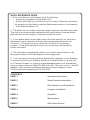
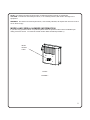
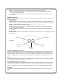
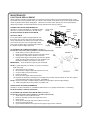
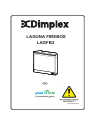
LAGUNA FIREBOX
LAGFB2
UK
08/51849/0 ISS1
QUICK REFERENCE GUIDE
1. Prior to the first use of the firebox verify the following:
• Are the circuit breakers for the firebox on?
• Are the light bulbs in your firebox loose? (to check, follow the instructions
for replacing the light bulbs under the Maintenance section of this manual)
• Is the firebox switched on?
2. The heater on your firebox may emit a slight, harmless odor when first used.
This odor is a normal condition caused by the initial heating of internal heater
parts and will not occur again, if required ventilate the room.
3. If your heater does not emit heat, ensure the main switch is on, the built-in
thermostat is set to maximum to begin with,and any wall switches for the
unit are on. If this does not work, switch the unit off for 5 minutes and
try again. Consult the Operation section of your practical users guide for
further information.
4. The information regarding the model of your firebox can be found on the
rating plate located on the side adjacent to the supply cord.
5. If you have any technical questions regarding the operation of your fireplace,
or require service for your fireplace, please go to www.dimplex.co.uk and click
on “Customer Support” or e-mail us at [email protected]. Alternatively,
ring our contact centre on 0844 879 3588 (UK only). This is a Lo-call no. from BT
landline - other providers including mobile phones may charge you more.
For ROI customers please phone 01 842 4833.
CONTENTS
PAGE 1
Important Instructions
PAGE 2
Model Number Information
PAGE 3
Site Selection and Preparation
PAGE 3
Fireplace Installation
PAGE 4
Operation
PAGE 6
Maintenance
PAGE 8
After Sales Service
IMPORTANT INSTRUCTIONS
PLEASE RETAIN THIS USER’S GUIDE FOR FUTURE REFERENCE
When using electrical appliances, basic precautions should always be followed to reduce the risk of fire,
electric shock, and injury to persons, including the following:
1. Read all instructions before using the electric firebox.
2. This firebox is hot when in use. To avoid burns, do not let bare skin touch hot surfaces. The trim
around the heater outlet becomes hot during heater operation. Keep combustible materials, such as
furniture, pillows, bedding, papers, clothes, and curtains at least 0.9m from the front and side of the
unit.
3. Extreme caution is necessary when any heater is used by or near children or invalids and whenever
the unit is left operating and unattended. For additional safety purchase a suitable fireguard.
4. Young children should be supervised to ensure that they do not play with the appliance.
5. The appliance is not intended for use by persons(including children) with reduced physical sensory or
mental capabilities, or lack of experience and knowledge, unless they have been given supervision or
instruction concerning the use of the appliance by a person responsible for their safety.
6. The appliance must be positioned so that the plug is accessible.
7. Always unplug the electric firebox when not in use.
8. If the supply cord is damaged, it must be replaced by the manufacturer, or its service agent, or a
qualified person in order to avoid a hazard.
9. Do not operate any unit with a damaged cord or plug, or if the heater has malfunctioned, or if the
electric firebox has been dropped or damaged in any manner. Return heater to authorized service
facility for examination, electrical or mechanical adjustment, or repair.
10. Do not use outdoors
11. Do not use this firebox in the immediate surroundings of a bath, a shower or a swimming pool.
12. Do not install the firebox directly on carpet or a similar surface which may restrict air circulation
beneath the unit.
13. Do not run the cord under carpeting. DO NOT COVER cord with throw rugs, runners, or the like.
Arrange cord away from traffic area and where it will not be tripped over.
14. Do not locate the heater immediately below a fixed socket-outlet.
15. To disconnect the firebox, turn the controls off, then remove the plug from the outlet.
16. Do not insert or allow foreign objects to enter any ventilation or outlet opening as this may cause an
electric shock or fire, or damage to the heater.
17. To prevent a possible fire, do not block air intake or outlet in any manner. Do not use on soft
surfaces, like a bed, where openings may become blocked.
18. Do not modify the electric firebox. Use it only as described in this manual. Any other use not
recommended by the manufacturer may cause fire, electric shock or injury to persons.
19. Avoid the use of an extension cord. Extension cords may overheat and cause a risk of fire.
20. Do not burn wood or other materials in the electric firebox.
21. Do not strike the firebox glass.
22. Always use a certified electrician should new circuits or outlets be required working to the current
addition of wiring regulations.
23. Always use properly grounded, and fused outlets.
24. Disconnect all power supply before performing any cleaning, maintenance or relocation of the unit.
25. When transporting or storing the unit and cord, keep in a dry place, free from excessive vibration and
store so as to avoid damage.
26. WARNING: In order to avoid overheating, DO NOT COVER the heater.
PLEASE SAVE THESE INSTRUCTIONS.
1
NOTE: Procedures and techniques that are considered important enough to emphasize.
CAUTION: Procedures and techniques which, if not carefully followed, will result in damage to the
equipment.
WARNING: Procedures and techniques which, if not carefully followed, will expose the user to the risk of
fire or serious injury.
MODEL AND SERIAL NUMBER INFORMATION
If you have any questions about our products please have the product model number available upon
calling customer service. To locate the model number label see below.(FIGURE 1)
Model
Number
Label
Firebox
FIGURE 1
2
NOTE
A 13amp, 230VAC circuit is required. A dedicated circuit is preferred but not essential in all cases. A
dedicated circuit will be required if, after installation, the circuit breaker trips or the fuse blows on a regular
basis when the heater is operating. Additional appliances on the same circuit may exceed the current
rating of the circuit breaker.
WARNING
Ensure the power cord is not installed so that it is pinched or against a sharp edge and ensure that the
power cord is stored or secured to avoid tripping or snagging to reduce the risk of fire, electric shock or
injury to persons.
Construction and electrical outlet wiring must comply with local building codes and other applicable
regulations to reduce the risk of fire, electric shock and injury to persons.
Do not attempt to wire your own new outlets or circuits. To reduce the risk of fire, electric shock or injury
to persons, always use a qualified electrician.
SITE SELECTION AND PREPARATION
This section provides instructions for selecting a location and preparing the site to install the firebox into
your Dimplex mantel surround.
1. Select a suitable location that is not susceptible to moisture and is away from drapes, furniture
and high traffic.
2. For ease of electrical hook up you may wish to locate the firebox near an existing outlet (refer
to NOTE).
3. Store the firebox in a safe dry and dust free location.
NOTE
The dimensions of the firebox are 768mm wide X 648mm high X 267mm deep. The viewing area is
765mm wide and 511mm high. The firebox does not require any additional venting.
FIREBOX INSTALLATION
1. INSTALL THE FIREBOX ASSEMBLY INTO A MANTEL (refer to mantel assembly instructions).
Please take care when placing firebox in mantel (2 person lift)
IMPORTANT
If not using a Dimplex mantel, the firebox must be installed in an enclosure with the following
MINIMUM internal/opening dimensions. (FIGURE 2)
FIGURE 2
658mm
775mm
300mm
2. NEW WALL CONSTRUCTION
1. Select a suitable location that is not susceptible to moisture and is away from drapes,
furniture and high traffic.
2. Place the firebox in the desired location to see how it will look in the room.
3. Mark the desired location on the floor and store the firebox in a safe, dry and dust free
location.
3
4. Use studs to frame an opening of 775mm wide X 658mm high X 300mm deep.
The power cord can be routed from behind the trim and along the wall to an outlet
near the fireplace. Please make sure the cord is not routed across the top of the firebox.
CAUTION
Clearance for air circulation beneath the firebox insert is provided by three rubber feet.
DO NOT INSTALL THE FIREBOX INSERT DIRECTLY ON CARPET OR SIMILAR SURFACES WHICH
MAY RESTRICT AIR CIRCULATION. If installing the firebox in a carpeted area, place a one-piece, solid,
flat surface under the firebox insert. Ensure that all three of the insert’s feet rest securely on this surface.
OPERATION
REMOTE CONTROL
The remote control has a range of approximately 15 meters.
REMOTE CONTROL INITIALIZATION
This procedure may be required if there is a loss of power to the remote
control in the firebox (i.e. power failure, breaker tripped, main power switch is
turned off, remote battery failure) or if a new remote is used.
1. Ensure that power is supplied through main service panel.
2. Locate manual controls. (FIGURE 4)
3. Activate main power switch.
4. Press — (ON) button located on the Manual Selection Control
for 3 seconds (FIGURE 5). All 3 indicators will flash.
5. Press the ON button on the transmitter (FIGURE 3). The
indicators will flash rapidly and then turn off.
This will synchronize the remote control transmitter and receiver.
REMOTE CONTROL USAGE
The remote control operates the firebox levels sequentially. The level is
increased every time the ON button on the transmitter is pressed. The firebox
can be turned off at any point by pressing the OFF button on the remote
control transmitter, or by switching off the mains switch.
FIGURE 3
Manual Controls Located
Under Door
Main Power Switch
Main Selector Switches
Thermostat Control
Indicator Lights
FIGURE 4
FIGURE 5
4
Level 1: The flame effect is turned on and the first red indicator light is activated.
Level 2: The flame effect remains on, and the PurifireTM is activated. The first and second red
indicator lights are activated.
Level 3: The flame effect remains on, the heater is activated, and all three red indicator lights are
activated.
MANUAL CONTROLS
The fireplace can also be controlled in a similar manner to the remote control with switches located on the
fireplace (FIGURE 6).
A. On Switch
Operates fireplace in the same manner as the remote control transmitter. Pressing this button has
the same effect as the ON button on the remote control. Pressing once to the activates Level 1, twice
activates Level 2, three times activates Level 3.
Level 1: The flame effect is turned on and the first red indicator light is activated.
Level 2: The flame effect remains on, and the PurifireTM is activated. The first and second red
indicator lights are activated.
Level 3: The flame effect remains on, the heater is activated, and all three red indicator lights are
activated.
B. Off Switch
Pressing this button has the same effect as the OFF button on the remote control. Pressing once will
shut the unit off.
A. ON Switch
B. OFF Switch
FIGURE 6
Level 1
Indicator
Level 3
Indicator
Level 2
Indicator
HEATER THERMOSTAT CONTROL
To adjust the temperature to your individual requirements, turn the thermostat control clockwise all the
way to turn on the heater. When the room reaches the desired temperature, turn the thermostat knob
counter clockwise until you hear a click. Leave in this position to maintain the room temperature at this
setting. For additional heat, turn clockwise until you hear the click again and the heater will turn on
NOTE
The heater may emit a slight harmless odor when first used. This odor is a normal condition caused by
initial heating of internal parts and will not occur again.
THE TEMPERATURE CUTOUT SWITCH
The heater on this fireplace is protected with a safety device to prevent overheating. Should the heater
overheat, an automatic cut out will turn the heater off. The heater will re-activate once the heater has
cooled. The overheat cutout may be triggered if the filter is dirty. Follow filter maintenance on Page 7.
CAUTION
If the heater continuously resets, disconnect the power at the main service panel and call your local
dealer.
5
MAINTENANCE
LIGHT BULB REPLACEMENT
Allow at least 5 minutes for light bulbs to cool before touching bulbs to avoid accidental burning of skin.
Light bulbs need to be replaced when you notice a dark section of the flame or when the clarity and detail
of the log ember bed exterior disappears. There are four bulbs under the log set, which generate the
flames and embers, and two bulbs above the log that illuminate the log exterior.
LOWER LIGHT BULB REQUIREMENTS
Quantity of 4 clear chandelier or candelabra bulbs
with an E-14 (small) socket base, 40 watt rating.
DO NOT EXCEED 40 WATTS PER BULB.
HELPFUL HINTS
It is a good idea to replace all light bulbs at one
time if they are close to the end of their rated life.
Group replacement will reduce the number of times
you need to open the unit to replace light bulbs.
Care must be taken when removing the logset as
the logset contains LED’s and wires.
FIGURE 7
Upper Light
Panel
Upper
Bulbs
Front
Glass
Logset
LED Wire
Harness
TO ACCESS THE LOWER BULB AREA (FIGURE 7)
Please take care when placing firebox in mantel (2 person lift)
1. Slide firebox out of mantel 50-75mm.
2. Remove 4 Phillips screws from the right side of trim.
3. Slide glass to right side of firebox to remove.
4. Pull the front edge of the plastic ember bed or plastic
grate up and forward until the rear tab releases from
the ledge located at the bottom of the mirror.
IMPORTANT: Only handle the logset by the emberbed.
Lower
Bulbs
Trim
FIGURE 8
NOTE: Logset fits tightly into firebox, so care is necessary
when removing.
5. Set logset in front of firebox.
6. Disconnect the logset LED wire harness from unit.
7. Unscrew bulbs counter clockwise.
8. Insert new bulbs.
9. Reconnect the logset LED wire harness.
10. Replace the logset by inserting the front edge of the firebox and push down on the rear edge of
the emberbed until it snaps into place. (FIGURE 8)
NOTE: Ensure the logset is installed tightly under the back ledge to prevent light leakage.
11. Slide front glass back into position and attach trim.
UPPER LIGHT BULB REQUIREMENTS
Quantity of 2 clear chandelier or candelabra bulbs with an E-14 (small) socket base, 7 watt rating.
DO NOT EXCEED 7 WATTS PER BULB
TO ACCESS THE UPPER LIGHT BULB AREA (FIGURE 7)
Please take care when placing firebox in mantel (2 person lift)
1. Slide firebox out of mantel 50-75mm.
2. Remove 4 Phillips screws from right side of trim.
3. Remove trim.
4. Slide glass to the right side of the firebox to remove.
5. Remove upper light panel.
6. Upper bulbs located in the upper left and upper right corners of firebox.
6
7. Unscrew bulbs counter clockwise.
8. Insert new bulbs.
9. Re-install upper light panel.
10. Slide front glass back into position and attach trim.
11. Re-insert the firebox. Please take care when placing firebox in mantel (2 person lift)
PURIFIRE™ FILTER
The Purifire™ filter supplied in your firebox is reusable and washable. The filter should be cleaned or
replaced on average once a year. To clean the filter gently tap filter on a hard surface to dislodge any
loose dirt or debris, and then clean with water. No soap or cleaning products are recommended. The
filter size is 508mm x 254mm x 25mm (20inch X 10inch X 1inch) rated at MERV 10.
TO REPLACE FILTER (FIGURE 9)
1. Remove firebox from mantel.
Please take care when placing firebox in mantel (2 person lift)
2. Filter can be accessed from the top rear of the unit.
3. Grasp filter and slide filter straight up.
4. Replace or clean filter.
NOTE
If after market air filter is used ensure it is installed according to the manufacturers recommended
instructions.
Air Filter
FIGURE 9
Firebox
GLASS CLEANING
The glass is cleaned in the factory during the assembly operation. During shipment, installation, handling,
etc., the glass may collect dust particles. These can be removed by dusting lightly with a clean dry cloth.
To remove fingerprints or other marks, the glass can be cleaned with a damp cloth. To prevent scratching, do not use abrasive cleaners or spray liquids on the glass surface.
FIREBOX SURFACE CLEANING
Use a cloth dampened with warm water only to clean painted surfaces of the electric firebox. Do not use
abrasive cleaners.
7
After Sales Service
Your product is guaranteed for one year from the date of purchase.
Within this period, we undertake to repair or exchange this product free of charge (excluding lamps or
batteries and subject to availibility) provided it has been installed and operated in accordance with these
instructions.
Your rights under this guarantee are additional to your statutory rights, which in turn are not affect by this
guarantee.
Should you require after sales service you should contact our customer services help desk on 0844 879
3588. It would assist us if you can quote the model number, series, date of purchase and the nature of the
fault at the time of your call. The customer services helpdesk will also be able to advise you should you
need to purchase any spares.
Please do not return any faullty product to us in the first instance as this may result in loss or damge and
delay in providing you with a staisfactory service.
Please retain your receipt as proof of purchase.
*Light bulbs and batteries are not covered in the warranty.
SERVICE
Contact your local dealer for service or warranty information.
RECYCLING
For electrical products sold in the European Community.
At the end of the electrical product’s useful life it should not be disposed of with household waste.
Please recycle where facilities exist. Check with your Local Authority or retailer for recycling
advice in your country.
The product complies with the European Safety Standard EN60335-2-30 and the
European Standard for Electromagnetic Compatibility (EMC) EN55014, EN61000
and EN50366 which cover the essential requirements of EEC Directives 2006/95
and 2004/108.
8
1. Warranty Card
2. Guarantee
Period (in Years)
5. Stamp & Signature of retailer
6. Fault/Defect
3. Model(s)
4. Date of Purchase
7. Contact Number & Address
Dimplex
A Division of GDC Group Ltd.
Millbrook House
Grange Drive
Hedge End
Southampton
Hampshire. SO30 2DF
TEL: 0844 879 3588
Fax. 0844 879 3582
WEBSITE: www.dimplex.co.uk
Republic of Ireland
TEL: 01 8424833
9