1
RELEASED APRIL
2002
CINEMA
REFERENCE
Mach II
Version 3.46
Installation
Manual
602-610 Mamaroneck Avenue, White Plains, NY, 10605, www.ada-usa.com, 1-800-HD-AUDIO, Fax (914) 946-9620
Safety Instructions & Electrical Warning
READ INSTRUCTIONS - All the safety and operating instructions should be read before the appliance is
operated.
RETAIN INSTRUCTIONS - The operating instructions should be retained for future reference.
HEED WARNING - All warnings on the appliance and in the operating instructions should be adhered to.
FOLLOW INSTRUCTIONS - All operating and use instructions should be followed.
WATER AND MOISTURE - The appliance should not be used near water - for example, near a bathtub,
washbowl, kitchen sink, laundry tub, in a wet basement, or near a swimming pool, etc.
LOCATION - The appliance should be installed in a stable location.
WALL OR CEILING MOUNT - The appliance should not be mounted to a wall or ceiling.
VENTILATION - The appliance should be situated so that its location or position does not interfere with its
proper ventilation. For example, the appliance should not be situated on a bed, sofa, rug or similar
surface that may block the ventilation openings.
HEAT - The appliance should be situated away from heat sources such as radiators, heat registers,
stoves, or other appliances that produce heat.
The lightning flash with the arrowhead, within an equilateral triangle,
is intended to alert the user of the
presence of uninsulated "dangerous voltage" within the product's
enclosure that may be of sufficient magnitude to constitute a
risk of electrical shock to persons.
POWER SOURCES - The appliance should be connected to a power supply only of the type described in
the operating instructions or as marked on the appliance.
GROUNDING - Make sure that this unit is always connected to a standard three-prong grounded outlet
(the circular pin is ground). When operating this unit at a higher voltage with a different power cord
configuration, consult your dealer for the proper power cord/outlet combination to use before operating this unit.
IMPORTANT
CAUTION
POWER CORD PROTECTION - Power supply cords should be routed so that they are not likely to be
walked on or pinched by items placed upon or against them, paying particular attention to cords at
plugs, convenience receptacles, and the point where they exit from the appliance.
RISK OF ELECTRIC SHOCK
DO NOT OPEN
CLEANING - The appliance should be cleaned only with a polishing cloth or a soft dry cloth. Never clean
with furniture wax, benzine, insecticides or other volatile liquids since they may corrode the face plate.
CAUTION: TO PREVENT RISK
OF ELECTRICAL SHOCK, DO
NOT REMOVE COVER (OR
BACK). NO USER-SERVICEABLE PARTS INSIDE. REFER
SERVICING TO QUALIFIED
SERVICE PERSONNEL.
POWER LINES - An outdoor antenna should be located away from power lines.
NONUSE PERIODS - The power cord of the appliance should be unplugged from the outlet when left
unused for a long period of time.
OBJECT AND LIQUID ENTRY - Care should be taken so that objects do not fall and liquids are not spilled
into the enclosure through openings.
DAMAGE REQUIRING SERVICE - The appliance should be serviced by an authorized service center or
qualified service personnel when:
•
•
•
•
•
The power supply cord or plug has been damaged; or
Objects have fallen, or liquid has been spilled into the appliance; or
The appliance has been exposed to rain; or
The appliance does not appear to operate normally or exhibits a marked
change in performance; or
The appliance has been dropped; or the enclosure has been damaged.
SERVICING - The user should not attempt to service the appliance beyond that described in the operating
instructions. For all other service requirements, the user should contact an Authorized Dealer or
Service Center.
WARNING:
TO REDUCE THE RISK OF FIRE OR ELECTRICAL SHOCK, DO NOT EXPOSE THIS APPLIANCE TO
RAIN OR MOISTURE. REPLACE FUSE ONLY AS MARKED.
CAUTION:
TO PREVENT ELECTRIC SHOCK, DO NOT PLUG THIS UNIT INTO ANY OUTLET OR EXTENSION
CORD WITHOUT THE STANDARD THREE-PRONG CONFIGURATION, WHERE THE CIRCULAR HOLE
IS USED FOR THE GROUND PLUG. ANY UNITS NOT SOLD IN THE UNITED STATES OR CANADA
ARE NOT SUPPLIED WITH A POWER CORD. THEREFORE, AN AUDIO DESIGN ASSOCIATES DEALER
SHOULD BE CONSULTED BEFORE CONNECTING THIS UNIT TO ANY POWER SOURCE.
The exclamation point within the
equilateral triangle is intended to
alert the user of the presence of
important operating and maintenance (servicing) instruction in the
literature accompanying the appliance.
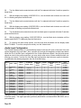
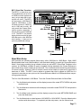
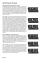
LINE VOLTAGE SELECTOR SWITCH AND REMOVABLE POWER CORD:
THIS UNIT IS EQUIPPED WITH A VOLTAGE SELECTOR SWITCH. IN MOST CASES, THIS SWITCH
WILL REMAIN IN THE 115V POSITION (SEE PICTURE BELOW), WHICH IS HOW THE UNIT LEAVES
THE FACTORY. HOWEVER, IF YOU WANT TO OPERATE THE UNIT IN AN AREA THAT USES THE
230V SETTING, CONSULT YOUR DEALER BEFORE PLUGGING THE UNIT IN. IN A CASE WHERE
THE 230V SETTING WOULD BE NEEDED, AUDIO DESIGN ASSOCIATES WILL NOT PROVIDE A POWER
CORD FOR THE UNIT. THEREFORE, THE USER MUST CONSULT AN AUTHORIZED DEALER OR
ADA TO OBTAIN THE PROPER POWER CORD, AS WELL. MAKE SURE THAT THE VOLTAGE SELECTOR SWITCH IS IN THE PROPER POSITION AND THAT YOU HAVE THE CORRECT POWER CORD
BEFORE THIS UNIT IS PLUGGED IN AND OPERATED!
115 V
Page 1
Contents
Safety Instructions & Electrical Warning ....................................................................................... 1
AC Connections ............................................................................................................................... 4
Power Amplifier (& Powered Subwoofer) Connections................................................................ 5
Introduction - Front Panel Controls & Displays ............................................................................ 6
Power On, Mute, Off, & Master Volume Control ............................................................................ 7
Input Selector ................................................................................................................................... 8
Record Selector ................................................................................................................................ 9
Rear Panel Connections ................................................................................................................ 10
Out of the Box Input Configuration .............................................................................................. 11
DVD Player Connection ................................................................................................................. 12
DVD Audio/SACD Player Connection ........................................................................................... 13
HDTV DVD Player Connection ...................................................................................................... 13
DSS Receiver Connection ............................................................................................................. 14
TOS-Link Optical Interconnects & Audio Dropouts .................................................................... 14
DSS Receiver Connection - Coaxial Connection ........................................................................ 15
DVR/PVR Connection .................................................................................................................... 16
DVR/PVR with Digtial Audio & VGA Video Connection .............................................................. 17
VCR Connection ............................................................................................................................. 18
Cable or TV Tuner Connection ..................................................................................................... 18
Digital or HDTV Cable/TV Tuner Connection.............................................................................. 19
CD Player Connection ................................................................................................................... 20
CD Player Digital Connections ..................................................................................................... 21
Tuner (Radio) Connection ............................................................................................................. 22
Auxiliary Component Connection ................................................................................................ 22
Multi-Room System Connection ................................................................................................... 23
Camcorder Connection ................................................................................................................. 23
Video Game Connection ................................................................................................................ 24
Computer Connection ................................................................................................................... 25
Phonograph Connection ............................................................................................................... 25
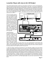
Laserdisc Player with Internal RF Demodulator ......................................................................... 26
Laserdisc Player with only an AC-3 RF Output ........................................................................... 27
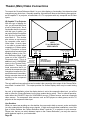
Theater (Main) Video Connections ............................................................................................... 28
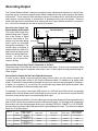
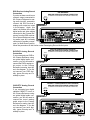
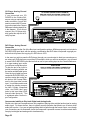
Recording Output........................................................................................................................... 30
Custom Input Configuration ......................................................................................................... 34
Final Input ................................................................................................................................................ 34
Label Inputs ............................................................................................................................................. 35
Audio Input Configuration ...................................................................................................................... 38
Composite Video Input Configuration ................................................................................................... 39
S-Video Input Configuration ................................................................................................................... 40
Component Video Input Configuration .................................................................................................. 40
RGB/HDTV/VGA Input Configuration ..................................................................................................... 40
HDTV Output Configuration ................................................................................................................... 40
Auxiliary DC Triggers .............................................................................................................................. 42
Turn On Input ........................................................................................................................................... 43
LCD Preview Display ............................................................................................................................... 44
Illumination .............................................................................................................................................. 44
Speaker Size Setup 1 ..................................................................................................................... 45
Subwoofer Crossover Point Setup ............................................................................................... 47
Multi-Pin Speaker Setup ................................................................................................................ 48
Multi-Pin Input LFE Boost Switch................................................................................................. 49
Speaker Level Setup 2 ................................................................................................................... 50
Balance Presets ............................................................................................................................. 52
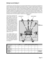
Delay Level Setup 3 ....................................................................................................................... 53
Page 2
Bass Setup 4 ................................................................................................................................... 55
Bass Limiter ............................................................................................................................................. 55
THX Ultra Setup 5 ........................................................................................................................... 56
Boundary Gain Control (BGC) ................................................................................................................ 56
Advanced Speaker Array (ASA) ............................................................................................................. 56
DTS LFE Settings ........................................................................................................................... 57
DTS LFE Adjustment Enable .................................................................................................................. 57
DTS LFE Adjustment ............................................................................................................................... 57
Tone Controls ................................................................................................................................. 58
Tone Presets - Out of the Box ................................................................................................................ 58
Recalling Tone Presets ........................................................................................................................... 59
Speaker Groups ....................................................................................................................................... 60
Treble Group A ......................................................................................................................................... 61
Bass Group A ........................................................................................................................................... 61
Treble Group B......................................................................................................................................... 61
Bass Group B ........................................................................................................................................... 62
Storing Tone Presets ............................................................................................................................... 62
Volume Setups ............................................................................................................................... 63
Storing Volume Presets .......................................................................................................................... 63
Recalling Volume Presets ....................................................................................................................... 63
Turn-On Volume Level Setup ................................................................................................................. 63
Maximum Volume Level .......................................................................................................................... 64
Analog Gain ............................................................................................................................................. 64
Channel Volume Adjustment ........................................................................................................ 65
Solo Mode ....................................................................................................................................... 65
RS-232 Control Options ................................................................................................................. 66
ADA Bus Data Port .................................................................................................................................. 66
ISO-232 ADA Bus to RS-232 Wired I/O Device ...................................................................................... 66
RS-232 Connection & Settings ............................................................................................................... 66
RS-232 Connection with Other ADA Bus Systems/Components ........................................................ 67
IRT-232 IR Transceiver to RS-232 Wireless I/O Device ........................................................................ 68
PC Setup & Control Software ................................................................................................................. 68
External IR Receiver Options ................................................................................................................. 69
Baud Rate Setup ...................................................................................................................................... 71
IR Transceiver (Front Panel) Settings .................................................................................................... 72
Address Setup ......................................................................................................................................... 72
Output Channel Indicator Lamps ................................................................................................. 74
Mode Selection ............................................................................................................................... 75
Multi-Channel Formats .................................................................................................................. 76
Cinema Modes & Indicator Lamps ............................................................................................... 77
Two Channel Modes & Indicator Lamps ...................................................................................... 80
Proprietary Two Channel ADA Modes .......................................................................................... 85
Fun Modes ...................................................................................................................................... 87
THX Enhancements ....................................................................................................................... 89
Dynamic Range .............................................................................................................................. 91
Default Modes ................................................................................................................................. 92
User Modes ..................................................................................................................................... 94
Appendix A - Out Of The Box Settings Overview ........................................................................ 96
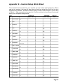
Appendix B - Custom Setup Work Sheet ..................................................................................... 97
Appendix C - Resetting Factory Defaults .................................................................................... 98
Appendix D - Master Reset Power Button (Vacation Switch) .................................................... 99
Appendix E - Cinema Reference Mach II PC Program .............................................................. 100
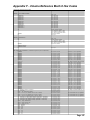
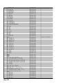
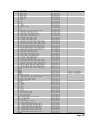
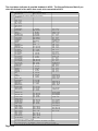
Appendix F - Cinema Reference Mach II Hex Codes ................................................................ 107
Dolby and the double-D symbol are trademarks of Dolby Laboratories Licensing Corporation. Confidential Unpublished Works. © Copyright 1992-2002,
Dolby Laboratories, Inc. All Rights Reserved. Lucasfilm and THX are trademarks or registered trademarks of Lucasfilm, Ltd. ©Lucasfilm Ltd. & TM.
Surround EX is a jointly developed technology of THX and Dolby Laboratories, Inc. and is a trademark of Dolby Laboratories, Inc. All rights reserved.
used under authorization. Manufactured under license from DTS Technology, LLC. DTS Digital Surround is a trademark of DTS Technology LLC.
©2002, Audio Design Associates, Inc. All rights reserved. Technical data and information contained in this manual is subject to change without notice.
Page 3
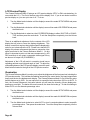
AC Connections
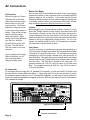
Before You Begin
As you remove the Cinema Reference Mach II from its packaging,
inspect the condition of the component prior to proceeding with the
following steps for AC connection. In the event that the Cinema
Reference Mach II appears to have suffered cosmetic damage due
to shipping, please contact your Authorized ADA Dealer immediately and do not proceed to plug the unit into an AC outlet.
AC Connection
Before you plug your Cinema
Reference into an AC outlet,
make certain that the voltage
selector switch is set to the
proper position. The Cinema
Reference’s safety fuse is set
to match the voltage selector’s
setting. There are two voltage
selector switches and two
safety fuse holders. When
viewing the Cinema Reference
from the front, the Main
Switch/Fuse are on the units
left side. The VGA Switch/
Fuse are located on the units
rear panel.
Caution
Before plugging your Cinema Reference Mach II into an AC outlet,
check the Voltage Selector Switch settings (the Main Switch and
Fuse holder is located on the units left side when looking at the
Cinema Reference from the front and the VGA Switch and Fuse
holder is located on the units back panel) and make certain that the
selector is set to your appropriate voltage position. For U.S. customers, this setting should be 115V. For international customers,
you may need to set this switch to 230V.
Fuse Values
For U.S. customers or international customers also operating on a
115V AC system, the Main fuse value of the Cinema Reference Mach
II should be a 1 Amp Slow Blow fuse. For international customers
operating on a 230V AC system, the Main fuse value should be 1/2
Amp Slow Blow. The safety Main fuse is located next to the Voltage
selector switch on the Cinema Reference’s left side (when viewing it
from the front.) The VGA fuse is located on the rear panel. For
systems operating at 115V AC, the fuse value is 2/10 Amp Slow
Blow. For systems operating at 230V AC, the VGA fuse value is
1/10 Amp Slow Blow.
If you are altering the Voltage
Selector Switches, you will
also most likely need to
change the safety fuses.
AC Connection
For customers who are using the U.S. standard AC receptacle, you will use the EIC AC Power Cord
provided with the Cinema Reference Mach II. Simply plug this AC cord into an operative AC outlet.
For customers who are using a non-U.S. standard AC receptacle, you will need to acquire an EIC AC
Power Cord with the appropriate receptacle connector. ADA only provides AC Power Cords with the
U.S. standard AC prongs.
"Dolby", "Pro Logic", & the double-D Symbol are trademarks of Dolby Laboratories. All rights reserved.
Manufactured under license from Digital Theater Systems, Inc. US Pat. No. 5,451,942, 5,956,764, 5,974,380, 5,978,762 and other worldwide
patents issued and pending. "DTS", "DTS-ES Extended Surround", and "Neo 6" are trademarks of Digital Theater Systems, Inc. © 1996,
2000 Digital Theater Systems, Inc. All rights reserved.
Manufactured under license from Lucasfilm Ltd. U.S. patent numbers 5,043,970; 5,189,703; and/or 5,222,059. European patent number
0323830. Other U.S. and foreign patents pending. Lucasfilm and THX are trademarks or registered trademarks of Lucasfilm Ltd. Surround
EX is a jointly developed technology of THX and Dolby Laboratories, Inc., and is a trademark of Dolby. Used under authorization.
VGA•RGBHV•HDTV INPUTS
2
3
VIDEO INPUTS
3
5
1
COMPOSITE & S-VIDEO
ARE UP-CONVERTED &
LINE-DOUBLED
VIDEO OUT
1
REC
7
1
VGA ONLY
PIN +/- CHAN PIN +/- CHAN
1 / 14 LT
7 / 20 SBL
2 / 15 CT
8 / 21 SBR
3 / 16 RT
9 /10/22 SHLD
4 / 17 SB
11 / 23 R.T.A
5 / 18 SL
12 / 24 R.T.B
6 / 19 SR
13 / 25 R.T.C
8 CHANNEL DB-25 INPUT
13
1
25 14
PIN
POINTS
Y
PB/B-Y
COMPONENT VIDEO
Y
PB/B-Y
PR/R-Y
PR/R-Y
6
8
1
REC
2
R
OSD
L
L
1
2
3
S-VIDEO INPUTS
2
4
3
SBL
L
4
5
1
3
R
R
AUDIO INPUTS
7
ADA NET™
RECORD
OUT
CAUTION
RISK OF ELECTRIC SHOCK
DO NOT OPEN
ATTENTION!
RISQUE DE CHOC ELECTRIQUE.
NE PAS OUVRIR
L
LS
R
C
Y
DIGITAL AUDIO
INPUTS
OPTICAL INPUTS
PB
1
PR
3
DATA PORT 12VDC OUT
Serial Data
115 V
115V
R
SBR
RS
R
SUB
1
2
3
4
2
4
AC OUTPUT
GND OUT IN 12VDC
Plug into an AC Outlet
AC INPUT
10A~ Max Switched 115V~60Hz/230V~50Hz
Plug into Cinema Reference
Page 4
Voltage
Selector &
Safety Fuse
On This
Side
100mA Max Per
ADA Bus® DC 1 DC 2
1 2 3 4 1- 2+ 1- 2+
MAIN
8
WARNING!
Risk Of Hazardous Energy! Make Proper Connections.
AVERTISSEMENT!
Energie Electrique Dangereuse! Faire Des Connexions Propres
Pour L'Hautparleur. Voir La Notice De Fonctionnement.
CAUTION: Disconnect Supply Cord Before Servicing.
ATTENTION: Debrancher Avant Le Depannage.
L
OUTPUT
L
6
CINEMA REFERENCE MACH II
HOME THEATER CONTROLLER
MADE IN U.S.A.
2
4
2
115V~2/10 A.S.B.
230V~1/10 A.S.B.
115V~60Hz/230V~50Hz
MULTI-PIN LFE SUM
0dB
+10dB
MAIN
VGASWITCHER
AC VOLTAGE
4
115 V
VGA•RGB•HDTV OUTPUT
PROCESSED
230V
Use Same
Value Fuse
115V~1AS.B.
230V~.5AS.B.
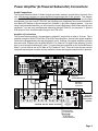
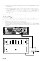
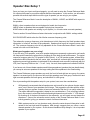
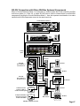
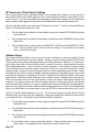
Power Amplifier (& Powered Subwoofer) Connections
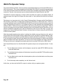
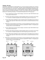
Audio Connections
The Cinema Reference Mach II’s Audio Outputs are clearly marked in a white field on the back of the
unit. ADA strongly suggests not using directional interconnects that lift the grounds. This diagram
includes ADA’s PTM-8150 Eight Channel Power Amplifier. While you may decide to vary the input
arrangement if you are using a PTM-8150, the following input arrangement will cause the amplifier’s
front panel LED display to spread outward from Channel 4, the center channel speaker. If you are
using a self-powered subwoofer, you will connect the Cinema Reference’s SUB Output directly to the
subwoofer. If you are using a self powered subwoofer with the PTM-8150, you may opt to “Y” split the
SUB output so as to illuminate channel eight of the PTM-8150.
Amplifier AC Connections
The Cinema Reference Mach II incorporates a switched AC outlet which is rated at 10 Amps. This is
powerful enough for ADA’s PTM-8150 or PTM-6150 Power Amplifiers. Several other power amplifiers
could also be plugged directly into this switched AC outlet. However, if the power amplifier is going to
draw more than 10 Amps (such as ADA’s MPA-501 Five Channel THX High-Power Amplifier), you will
want to avoid using this switched AC outlet. To connect the power amplifier to the Cinema Reference
Mach II, you will need to use an EIC Male to EIC Female AC Cord. These AC cords are also used for
computers and computer monitors and are available in stores that support computer and AC products.
"Dolby", "Pro Logic", & the double-D Symbol are trademarks of Dolby Laboratories. All rights reserved.
Manufactured under license from Digital Theater Systems, Inc. US Pat. No. 5,451,942, 5,956,764, 5,974,380, 5,978,762 and other worldwide
patents issued and pending. "DTS", "DTS-ES Extended Surround", and "Neo 6" are trademarks of Digital Theater Systems, Inc. ' 1996,
2000 Digital Theater Systems, Inc. All rights reserved.
Manufactured under license from Lucasfilm Ltd. U.S. patent numbers 5,043,970; 5,189,703; and/or 5,222,059. European patent number
0323830. Other U.S. and foreign patents pending. Lucasfilm and THX are trademarks or registered trademarks of Lucasfilm Ltd. Surround
EX is a jointly developed technology of THX and Dolby Laboratories, Inc., and is a trademark of Dolby. Used under authorization.
VGA¥RGBHV¥HDTV INPUTS
2
3
VIDEO INPUTS
5
3
1
VIDEO OUT
REC
1
7
PIN +/1 / 14
2 / 15
3 / 16
4 / 17
5 / 18
6 / 19
1
VGA ONLY
COMPOSITE & S-VIDEO
ARE UP-CONVERTED &
LINE-DOUBLED
8 CHANNEL DB-25 INPUT
13
1
25 14
PIN
POINTS
Y
MULTI-PIN LFE SUM
0dB
+10dB
PB/B-Y
COMPONENT VIDEO
Y
PR/R-Y
PB/B-Y
L
L
1
REC
S-VIDEO INPUTS
2
4
3
3
2
R
R
SBL
L
1
3
1
R
ATTENTION!
R
L
LS
C
PB
1
Y
DIGITAL AUDIO
INPUTS
OPTICAL INPUTS
PR
3
4
MAIN
8
WARNING!
Risk Of Hazardous Energy! Make Proper Connections.
AVERTISSEMENT!
Energie Electrique Dangereuse! Faire Des Connexions Propres
Pour L’Hautparleur. Voir La Notice De Fonctionnement.
CAUTION: Disconnect Supply Cord Before Servicing.
ATTENTION: Debrancher Avant Le Depannage.
L
OUTPUT
L
7
6
5
4
3
2
1
CAUTION
RISK OF ELECTRIC SHOCK
DO NOT OPEN
RISQUE DE CHOC ELECTRIQUE.
NE PAS OUVRIR
MADE IN U.S.A.
OSD
2
8
6
4
CINEMA REFERENCE MACH II
HOME THEATER CONTROLLER
ADA NET“
RECORD
OUT
PR/R-Y
2
2
115V~2/10 A.S.B.
230V~1/10 A.S.B.
115V~60Hz/230V~50Hz
CHAN PIN +/- CHAN
LT
7 / 20 SBL
CT
8 / 21 SBR
RT
9 /10/22 SHLD
SB
11 / 23 R.T.A
SL
12 / 24 R.T.B
SR
13 / 25 R.T.C
MAIN
VGASWITCHER
AC VOLTAGE
4
115 V
VGA¥RGB¥HDTV OUTPUT
PROCESSED
DATA PORT 12VDC OUT
100mA Max Per
Serial Data
ADA Bus¤ DC 1 DC 2
1 2 3 4 1- 2+ 1- 2+
115 V
115V
R
SBR
AUDIO INPUTS
R
RS
7
SUB
6 5
1
2
3
Voltage
Selector &
Safety Fuse
On This
Side
2
4
4
AC OUTPUT
GND OUT IN 12VDC
AC INPUT
10A~ Max Switched 115V~60Hz/230V~50Hz
8
230V
Use Same
Value Fuse
115V~1AS.B.
230V~.5AS.B.
Plug into
Cinema Reference
EIC Male to
EIC Female
Power Cord
EIGHT CHANNEL
BLPOWER AMPLIFIER
OUTPUT
2-16Ω
-
+
OUTPUT
2-16Ω
INPUT
47KΩ
CH
1
-
R
INPUT
47KΩ
+
L
LS
OUTPUT
2-16Ω
INPUT
47KΩ
CH
2
-
S
BR
RS
CH
5
OUTPUT
2-16Ω
+
-
INPUT
47KΩ
CH
6
+
OUTPUT
2-16Ω
+
-
INPUT
47KΩ
INPUT
47KΩ
CH
3
CH
7
OUTPUT
2-16Ω
-
+
S
OUTPUT
2-16Ω
+
1500W POWER
115 V~/60 Hz • 230 V~/50 Hz
C
-
INPUT
47KΩ
CH
8
CAUTION
RISK OF ELECTRIC SHOCK
DO NOT OPEN
INPUT
47KΩ
CH
4
ATTENTION!
RISQUE DE CHOC ELECTRIQUE.
NE PAS OUVRIR
MADE IN U.S.A.
OUTPUT
2-16Ω
+
CAUTION! DO NOT SHORT OUTPUTS!
-
CAUTION:
DISCONNECT SUPPLY
CORD BEFORE
SERVICING.
ATTENTION:
DEBRANCHER AVANT
LE DEPANNAGE.
WARNING!
RISK OF HAZARDOUS
ENERGY!
MAKE PROPER SPEAKER
CONNECTIONS.
Plug into
PTM-8150 or
another power
amplifier.
REPLACE
WITH SAME
VALUE FUSE
10A S.B.~115V
5A S.B.~230V
VOLTAGE
SWITCH
230 V~
115 V~
115 V
PTM-8150S
AVERTISSEMENT! ENERGIE
ELECTRIQUE DANGEREUSE! FAIRE
DES CONNEXIONS PROPRES POUR
L'HAUTPARLEUR. VOIR LA NOTICE
DE FONCTIONNEMENT.
Sub Output To
Power Amplifier
For Passive Subs
Or Sub Output To
Powered Subwoofer
Page 5
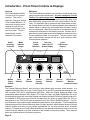
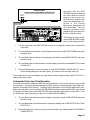
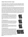
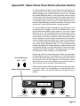
Introduction - Front Panel Controls & Displays
Overview
The Cinema Reference Mach
II is factory set for optimum
operation. This section
details the front panel features
of the Cinema Reference. All
component functions can be
operated through the five
control knobs located on the
units front panel. The front
panel displays are also
explained in this section.
Active
Incoming
Channels
Welcome
The Cinema Reference Mach II is the world’s most advanced audio
video surround sound preamplifier. It is also configured “Out Of
The Box” for optimum operation. While it is designed to be easy
to setup and operate, ADA strongly recommends spending some
time familiarizing yourself with the units many functions and features. For those who wish to customize their home theater system,
the Cinema Reference Mach II is also equipped to be configured to
operate ideally in almost any environment and with many varying
source components. While the connection of components and accessories are discussed in the following sections, this area will explain the front panel features and basic operation commands of the
Cinema Reference Mach II’s front panel. The text found in italic
type in this manual’s margins will act as a quick reference when
reviewing these materials.
Active
Output
Channels
Mode
Indicator
Lamps
Two-Line
Back-Lit LCD
Status Display
Color
LCD Preview
Display
SELECT SERIES
DVD DISC 1
ALL -24.0 DB
Cinema Reference MACH II
Master
Reset
Switch
Input
Selector
UM
VOL E
C
MODE
N
HA NE
L
INPUT
CORD
RE
MADE IN U.S.A.
Mode
Selector
Volume
Control
& On/Off
Channel
Selector
Record
Selector
LCD Preview
Monitor
Contrast Control
Features
The Cinema Reference Mach II acts as both an input selector and surround sound decoder. It is
capable of decoding Dolby Pro Logic, Dolby Digital (AC-3), and DTS encoded formats and also provide Lucasfilm THX Ultra 2 enhancements and filters. While the Cinema Reference Mach II can
automatically detect between Dolby Digital, DTS, Dolby Pro Logic, and Dolby Digital/Dolby Pro Logic
(both decoding formats are used when playing two-channel encoded DVD discs {typically older movies available on DVD that are not mixed in six channels}), the option to engage either full THX enhancements or only THX Re-EQ must be manually set on the Cinema Reference Mach II. The Cinema Reference also provides several additional modes ideal for music playback. There are additional
settings that permit the Cinema Reference Mach II to also operate in home theaters where a full eight
channel speaker array may only be partially implemented (i.e. no back surround and/or no center
channel). Furthermore, the Cinema Reference Mach II also permits each channel to be set to its own
volume level with respect to all other channels as well as have its own delay setting. These features
and more are discussed in the upcoming sections.
Page 6
Power On, Mute, Off, & Master Volume Control
When the Cinema Reference is off, turning any knob or pushing any
knob other than the Volume knob will cause the Cinema Reference’s
center LCD display to indicate:
Power On
Press the Cinema Reference’s
Volume knob to engage power
on.
PUSH VOLUME
FOR POWER ON
Front Plate
To turn on the Cinema Reference, providing the unit is not in
Mute, press the Volume knob once. Pressing of the Volume
knob performs only three functions.
If the unit is off, pressing it will turn it on.
If the unit is on, pressing it once will engage Mute.
If the unit is in Mute, pressing it again will turn it off.
Press Knob
To Turn On
Press Knob
Once To Mute
(To regain the audio (exit Mute), turn the Volume knob).
Raise Vo
r&
lum
e
ow
UM
VOL E
e
L
Press Knob
Twice For Off
Once the Cinema Reference
is on, turning the Volume knob
will only raise or lower the
system’s volume level. This
is considered the Master Volume Control as it will adjust
all eight channels of volume,
maintaining the balance of levels that are preset between
channels.
Side View
Chassis Side
Mute
While the Cinema Reference is
on, pressing it’s Volume knob
once will mute all channels.
Power Off
While the Cinema Reference is
in Mute, pressing the Volume
knob a second time will turn
the Cinema Reference off.
Un-Mute
While the Cinema Reference is
in Mute, turning the volume
knob, will regain audio.
Power On/Off Via AC Control
If the Cinema Reference is on
when it is unplugged or when
power is removed through the
use of an AC Controller, it will
also automatically turn back
on when power is restored.
Page 7
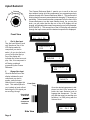
The Cinema Reference Mach II permits you to scroll to the next
input without having all of the components you are passing actively
process through the Cinema Reference Mach II. This prevents the
clicking that is commonly associated with changing TV channels up
and down. To best access another component from the front of the
Cinema Reference, turn the Input Selector knob. As you turn this
knob, you will notice that the top row of the LCD display will not
change, still indicating the current component in use (in this example,
DVD PLAYER 1). The second line of the LCD display will advance
through the input names until the desired component is displayed.
elect
To S pon Anoth
n
ent
e
ur Com
r
T
Input Selector
INPUT
Front View
DVD PLAYER 1
ALL -24.0 DB
1.
Dial In New Input
Turn the Input Selector knob
until the second line of the
LCD display reads the
component you wish to
select. As you turn the knob,
you will notice that the top
line of the display still
indicates the current source in
play. Also, this component is
still being routed and
processed by the Cinema
Reference.
DVD PLAYER 1
DSS
2
DVD PLAYER 1
DVR/PVR
3
DVD PLAYER 1
VCR
4
2.
Engage New Input
Once the second line of the
display indicates the next
component you wish to
access, press the Input
Selector knob to engage this Front Plate
input. This method permits
you to select an input without
switching all of the inputs you
are scrolling through.
DVD PLAYER 1
CABLE/TV
5
Once the desired component is displayed on the LCD’s second row,
press the Input Selector knob to
engage that component. The display will then return to read the new
selection (i.e. DSS) along with the
Volume Level.
Press Knob
To Activate
The New
Component
Selection
CABLE/TV
5
ALL -24.0 DB
Side View
Page 8
Chassis Side
R
nt
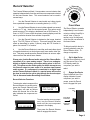
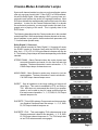
The Cinema Reference Mach II incorporates a record selector that
operates independently from the actual source component selected
for the home theater room. This record selector can be used in
several ways.
o Select Anot
T
n
Compo he
ne
ur cord
e
ECORD
r
T
Record Selector
R
1
Use the Record Selector to send audio and video signals
from a particular component to a recording device (i.e. VCR)
2
Use the Record Selector to send a video signals to a second
monitor or TV set. Ideal for the sports fanatic, this option would
permit a second TV to display a broadcast from a DSS receiver, TV
tuner, or VCR TV tuner, while the primary viewing display would be
set to a particular channel from another component.
3
Use the Record Selector to determine the image inserted
into a TV’s PIP (Picture In Picture). This would provide the same
effect as described in option 2 (above) using the PIP function in
place of a second TV or monitor.
4
Use the Record Selector to send the audio and video signal
of a particular device to a whole-house multi-room audio video system. This setup would cause the Record Selector to act as a separate zone from the actual home theater.
Please note, that the Record audio output of the Cinema Reference Mach II is a pure analog output. There is no analog-todigital or digital-to-analog conversion taking place in this circuit. This preserves the audio quality for those who opt to use
the Record output to pass audio to a premium two-channel
audio system. If a component is connected to a digital input
on the Cinema Reference Mach II, a special setup will need to
be done in order for the unit to play through the record output.
This is discussed under Recording Connections.
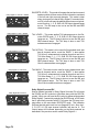
Record Selector Functions
To determine what component the
Record Selector is currently set to,
press the Record Selector knob.
The display will read as follows
where the second line of the display indicates the component selected.
RECORD INPUT
DSS RECORD15
RECORD TAKEN
DVD PLAYER 1
To select another source component, turn the Record Selector
knob until the new component
appears in the display.
Then press the Record Selector
knob to engage this device.
Front View
The Record Selector operates
independently from the main
output providing the ability to
record, view, or play (in
another room) a component
other than the one selected in
the home theater.
To determine which device is
currently selected, press the
Record Selector knob. To
change components:
1.
Dial In New Device
Turn the Record Selector knob
until the second line of the
LCD display reads the
component you wish to
select.
2.
Engage New Device
Once the second line of the
display indicates the next
component you wish to
access, press the Record
knob to engage this input.
Front Plate
Press Knob
To Activate
The New
Component
Selection
Side View
Chassis Side
Page 9
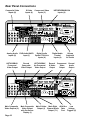
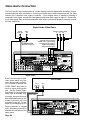
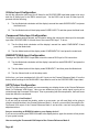
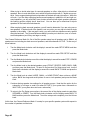
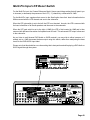
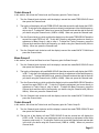
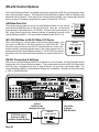
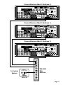
Rear Panel Connections
Composite Video
Inputs (8)
S-Video
Inputs (4)
Component Video
Inputs (3)
HDTV¥RGBHV¥VGA
Inputs (4)
"Dolby", "Pro Logic", & the double-D Symbol are trademarks of Dolby Laboratories. All rights reserved.
Manufactured under license from Digital Theater Systems, Inc. US Pat. No. 5,451,942, 5,956,764, 5,974,380, 5,978,762 and other worldwide
patents issued and pending. "DTS", "DTS-ES Extended Surround", and "Neo 6" are trademarks of Digital Theater Systems, Inc. ' 1996,
2000 Digital Theater Systems, Inc. All rights reserved.
Manufactured under license from Lucasfilm Ltd. U.S. patent numbers 5,043,970; 5,189,703; and/or 5,222,059. European patent number
0323830. Other U.S. and foreign patents pending. Lucasfilm and THX are trademarks or registered trademarks of Lucasfilm Ltd. Surround
EX is a jointly developed technology of THX and Dolby Laboratories, Inc., and is a trademark of Dolby. Used under authorization.
VGA¥RGBHV¥HDTV INPUTS
2
3
VIDEO INPUTS
3
5
1
VIDEO OUT
1
REC
7
PIN +/1 / 14
2 / 15
3 / 16
4 / 17
5 / 18
6 / 19
1
VGA ONLY
COMPOSITE & S-VIDEO
ARE UP-CONVERTED &
LINE-DOUBLED
8 CHANNEL DB-25 INPUT
13
1
25 14
PIN
POINTS
Y
MULTI-PIN LFE SUM
0dB
+10dB
PB/B-Y
COMPONENT VIDEO
Y
PR/R-Y
PB/B-Y
PR/R-Y
6
8
2
OSD
L
L
2
1
S-VIDEO INPUTS
2
4
3
4
5
R
R
SBL
L
3
1
3
7
R
ATTENTION!
WARNING!
Risk Of Hazardous Energy! Make Proper Connections.
AVERTISSEMENT!
Energie Electrique Dangereuse! Faire Des Connexions Propres
Pour L’Hautparleur. Voir La Notice De Fonctionnement.
CAUTION: Disconnect Supply Cord Before Servicing.
ATTENTION: Debrancher Avant Le Depannage.
L
PB
1
Y
DIGITAL AUDIO
INPUTS
OPTICAL INPUTS
C
PR
3
DATA PORT 12VDC OUT
Serial Data
115 V
115V
R
SBR
R
RS
SUB
1
2
3
2
4
4
Record
Composite
Video Output
AC OUTPUT
GND OUT IN 12VDC
AC INPUT
10A~ Max Switched 115V~60Hz/230V~50Hz
230V
Use Same
Value Fuse
115V~1AS.B.
230V~.5AS.B.
10 Amp
Switched
AC Outlet
Digital Audio
Coaxial
Inputs (4)
Record
Audio
Output
Component
Video
Output
Record
S-Video
Output
HDTV-RGBHV
Un-Processed
Video Output
Voltage
Selector &
Safety Fuse
On This
Side
100mA Max Per
ADA Bus¤ DC 1 DC 2
1 2 3 4 1- 2+ 1- 2+
MAIN
DVD Audio/SACD
Digital Audio
Input (1)
Optical TOS-Link
Inputs (4)
HDTV-RGBHV
Processed
Video Output
CAUTION
RISK OF ELECTRIC SHOCK
DO NOT OPEN
RISQUE DE CHOC ELECTRIQUE.
NE PAS OUVRIR
R
L
LS
8
AUDIO INPUTS
Analog Audio
Inputs (8)
ADA NET“
RECORD
OUT
OUTPUT
L
6
CINEMA REFERENCE MACH II
HOME THEATER CONTROLLER
MADE IN U.S.A.
1
REC
2
4
2
115V~2/10 A.S.B.
230V~1/10 A.S.B.
115V~60Hz/230V~50Hz
CHAN PIN +/- CHAN
LT
7 / 20 SBL
CT
8 / 21 SBR
RT
9 /10/22 SHLD
SB
11 / 23 R.T.A
SL
12 / 24 R.T.B
SR
13 / 25 R.T.C
MAIN
VGASWITCHER
AC VOLTAGE
4
115 V
VGA¥RGB¥HDTV OUTPUT
PROCESSED
"Dolby", "Pro Logic", & the double-D Symbol are trademarks of Dolby Laboratories. All rights reserved.
Manufactured under license from Digital Theater Systems, Inc. US Pat. No. 5,451,942, 5,956,764, 5,974,380, 5,978,762 and other worldwide
patents issued and pending. "DTS", "DTS-ES Extended Surround", and "Neo 6" are trademarks of Digital Theater Systems, Inc. ' 1996,
2000 Digital Theater Systems, Inc. All rights reserved.
Manufactured under license from Lucasfilm Ltd. U.S. patent numbers 5,043,970; 5,189,703; and/or 5,222,059. European patent number
0323830. Other U.S. and foreign patents pending. Lucasfilm and THX are trademarks or registered trademarks of Lucasfilm Ltd. Surround
EX is a jointly developed technology of THX and Dolby Laboratories, Inc., and is a trademark of Dolby. Used under authorization.
VGA¥RGBHV¥HDTV INPUTS
2
3
VIDEO INPUTS
3
5
1
COMPOSITE & S-VIDEO
ARE UP-CONVERTED &
LINE-DOUBLED
VIDEO OUT
1
REC
7
1
VGA ONLY
PIN +/- CHAN PIN +/- CHAN
1 / 14 LT
7 / 20 SBL
2 / 15 CT
8 / 21 SBR
3 / 16 RT
9 /10/22 SHLD
4 / 17 SB
11 / 23 R.T.A
5 / 18 SL
12 / 24 R.T.B
6 / 19 SR
13 / 25 R.T.C
8 CHANNEL DB-25 INPUT
13
1
25 14
PIN
POINTS
Y
PB/B-Y
COMPONENT VIDEO
Y
PB/B-Y
PR/R-Y
PR/R-Y
6
8
1
REC
2
R
OSD
L
L
1
2
3
S-VIDEO INPUTS
2
4
3
5
R
1
3
Main Composite
Video Outputs (2)
7
ADA NET“
CAUTION
RISK OF ELECTRIC SHOCK
DO NOT OPEN
ATTENTION!
RISQUE DE CHOC ELECTRIQUE.
NE PAS OUVRIR
L
LS
R
C
Y
DIGITAL AUDIO
INPUTS
OPTICAL INPUTS
PB
1
PR
3
DATA PORT 12VDC OUT
Serial Data
115 V
115V
R
SBR
RS
Main Composite
Video Output
with On-Screen
Display (1)
R
SUB
1
2
3
4
2
4
AC OUTPUT
GND OUT IN 12VDC
Voltage
Selector &
Safety Fuse
On This
Side
100mA Max Per
ADA Bus¤ DC 1 DC 2
1 2 3 4 1- 2+ 1- 2+
MAIN
8
WARNING!
Risk Of Hazardous Energy! Make Proper Connections.
AVERTISSEMENT!
Energie Electrique Dangereuse! Faire Des Connexions Propres
Pour L’Hautparleur. Voir La Notice De Fonctionnement.
CAUTION: Disconnect Supply Cord Before Servicing.
ATTENTION: Debrancher Avant Le Depannage.
L
OUTPUT
L
6
R
AUDIO INPUTS
Page 10
SBL
L
4
RECORD
OUT
CINEMA REFERENCE MACH II
HOME THEATER CONTROLLER
MADE IN U.S.A.
2
4
2
115V~2/10 A.S.B.
230V~1/10 A.S.B.
115V~60Hz/230V~50Hz
MULTI-PIN LFE SUM
0dB
+10dB
MAIN
VGASWITCHER
AC VOLTAGE
4
115 V
VGA¥RGB¥HDTV OUTPUT
PROCESSED
AC INPUT
10A~ Max Switched 115V~60Hz/230V~50Hz
230V
Use Same
Value Fuse
115V~1AS.B.
230V~.5AS.B.
Low
Main S-Video Main Eight ADA Bus
Voltage
Output (1) Channel Audio Data
Port Triggers (2)
Output (7.1)
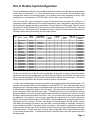
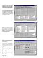
Out of the Box Input Configuration
The Cinema Reference Mach II is an incredibly flexible home theater controller that can accommodate
a wide array of components. For easy and quick setup, one can use the “Out of the Box” input
configurations shown on the following pages. One can also elect to do a completely “Custom” input
configuration or a combination of “Out of the Box” and “Custom” input configurations.
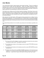
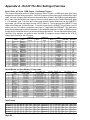
The “Out of the Box” input configuration is easy to follow and offers connection of as many as 15
components without adjustment of the Cinema Reference’s input configurations (providing that the
sources have the appropriate outputs and that the TV has at least an S-Video input). Below is a chart
showing the Cinema Reference’s 20 “input labels” and the assignment of the A/V jacks on the rear
panel of the unit. While there are 20 available input labels, the Out of the Box setup utilizes only the
first fifteen labels were the remaining five are record options.
INPUT
#
1
2
3
4
5
6
7
8
9
10
11
12
13
14
15
16
17
18
19
20
INPUT LABEL
DVD PLAYER
DSS
DVR/PVR
VCR
CABLE/TV
CD PLAYER
TUNER
AUXILIARY
DVD AUDIO
MULTI-ROOM
CAMCORDER
VIDEO GAME
COMPUTER
LASERDISC
LASER AC3
PHONOGRPH
DSS RECORD
DVR RECORD
TV RECORD
CD RECORD
AUDIO
INPUT
ALTERNATE
AUDIO INPUT
COMPOSITE
VIDEO
INPUT
S-VIDEO
INPUT
DIGITAL 1
OPTICAL 2
ANALOG 3
ANALOG 4
ANALOG 5
ANALOG 6
ANALOG 7
ANALOG 8
MULTI-PIN
ANALOG 2
ANALOG 1
DIGITAL 3
DIGITAL 4
OPTICAL 1
DIGITAL 2
ANALOG 1
ANALOG 2
ANALOG 3
ANALOG 5
ANALOG 6
DIGITAL 2
OPTICAL 3
OPTICAL 4
OPTICAL 1
OPTICAL 1
OPTICAL 1
-
1
2
3
4
5
8
1
7
6
8
8
2
3
5
-
1
2
3
4
1
2
3
-
COMPONENT
HDTV
RGB (HV)
VIDEO
CONVERSION
INPUT
INPUT
OUTPUT
1
2
1
3
2
-
1
2
3
4
1
1
2
3
4
-
S-VIDEO
S-VIDEO
S-VIDEO
COMPOSITE
COMPOSITE
COMPOSITE
COMPOSITE
COMPOSITE
COMPOSITE
COMPOSITE
COMPOSITE
COMPOSITE
RGB
COMPOSITE
COMPOSITE
COMPOSITE
COMPOSITE
COMPOSITE
COMPOSITE
COMPOSITE
Please note, that the Out of the Box input configuration is designed to maximize the home theater
experience. Because only analog audio connections play through the record output, the components
that are connected digitally (DVD, DSS) will not provide audio through the record output. This can be
changed and is discussed in the Record Connection section of this manual.
“Custom” input configuration permits any input label to be renamed to best suit the actual system. For
example, the input label DSS could be changed to read SATELLITE. Also, each input label can be
assigned to any of the eight analog or eight digital audio inputs, as they do not have to be fixed to the
A/V jacks that are assigned in the Out of the Box setup. The same is true for the composite video, SVideo, component video, and RGB video inputs. This flexibility permits you to maximize the Cinema
Reference Mach II’s A/V jacks to accommodate a wide assortment of components. Lastly, the Cinema
Reference features an option called Final Input. Here, you can reduce the number of input labels that
are displayed. For example, if you are only connecting six components to the Cinema Reference
Mach II, you could set the final input to CD PLAYER 6. After this adjustment, turning the input knob will
only display the first six inputs. As such, combining the Final Input feature with the ability to rename
input labels and reassign A/V jacks to any input label, one has the ability to completely customize a
Cinema Reference Mach II to perfectly match any system. And should a component be added at
some later time, the final input can be opened back up to seven (or more) to accommodate connection
of the new devices. To learn more about “Custom” input configuration of the Cinema Reference Mach
II, skip forward to this section. To proceed with the Out of the Box setup, follow the instructions on the
following pages.
Page 11
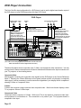
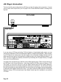
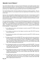
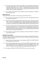
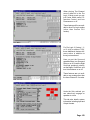
DVD Player Connection
The Out of the Box input configuration for a DVD player is set to use the digital coaxial audio output of
the DVD player as most DVD players have this type of RCA jack.
DVD Player
PCM/AC-3/DTS Video
Digital Out
Out
S-Video
Out
Component Video Output
Y
Cr
Cb
S-Video Cable
(Primary Video Connection
providing TV has S-Video Input)
Video Cable
Component Video
(Optional video connection
providing that TV has
component video inputs.
If TV has component video,
S-Video Input #1 can be used
for an alternate component.
(When driving the TV with
S-Video or component
video, this cable is still
required to drive the Cinema
Reference’s LCD display.
"Dolby", "Pro Logic", & the double-D Symbol are trademarks of Dolby Laboratories. All rights reserved.
Manufactured under license from Digital Theater Systems, Inc. US Pat. No. 5,451,942, 5,956,764, 5,974,380, 5,978,762 and other worldwide
patents issued and pending. "DTS", "DTS-ES Extended Surround", and "Neo 6" are trademarks of Digital Theater Systems, Inc. ' 1996,
2000 Digital Theater Systems, Inc. All rights reserved.
Manufactured under license from Lucasfilm Ltd. U.S. patent numbers 5,043,970; 5,189,703; and/or 5,222,059. European patent number
0323830. Other U.S. and foreign patents pending. Lucasfilm and THX are trademarks or registered trademarks of Lucasfilm Ltd. Surround
EX is a jointly developed technology of THX and Dolby Laboratories, Inc., and is a trademark of Dolby. Used under authorization.
VGA¥RGBHV¥HDTV INPUTS
2
3
VIDEO INPUTS
3
5
1
COMPOSITE & S-VIDEO
ARE UP-CONVERTED &
LINE-DOUBLED
VIDEO OUT
1
REC
7
PIN +/- CHAN PIN +/- CHAN
1 / 14 LT
7 / 20 SBL
2 / 15 CT
8 / 21 SBR
3 / 16 RT
9 /10/22 SHLD
4 / 17 SB
11 / 23 R.T.A
5 / 18 SL
12 / 24 R.T.B
6 / 19 SR
13 / 25 R.T.C
1
8 CHANNEL DB-25 INPUT
13
1
25 14
1
MULTI-PIN LFE SUM
0dB
+10dB
MAIN
1
VGA ONLY
1
REC
1
PIN
POINTS
Y
PB/B-Y
VGASWITCHER
AC VOLTAGE
4
1
115V~60Hz/230V~50Hz
COMPONENT VIDEO
Y
PR/R-Y
PB/B-Y
PR/R-Y
4
6
8
2
R
OSD
L
L
1
2
3
S-VIDEO INPUTS
2
4
3
SBL
L
4
5
R
1
3
AUDIO INPUTS
7
ADA NET“
CAUTION
RISK OF ELECTRIC SHOCK
DO NOT OPEN
ATTENTION!
RISQUE DE CHOC ELECTRIQUE.
NE PAS OUVRIR
L
LS
R
C
Y
DIGITAL AUDIO
INPUTS
OPTICAL INPUTS
PB
1
PR
3
DATA PORT 12VDC OUT
Serial Data
115 V
115V
R
SBR
RS
R
SUB
1
2
3
4
1
2
4
AC OUTPUT
GND OUT IN 12VDC
Voltage
Selector &
Safety Fuse
On This
Side
100mA Max Per
ADA Bus¤ DC 1 DC 2
1 2 3 4 1- 2+ 1- 2+
MAIN
8
WARNING!
Risk Of Hazardous Energy! Make Proper Connections.
AVERTISSEMENT!
Energie Electrique Dangereuse! Faire Des Connexions Propres
Pour L’Hautparleur. Voir La Notice De Fonctionnement.
CAUTION: Disconnect Supply Cord Before Servicing.
ATTENTION: Debrancher Avant Le Depannage.
L
OUTPUT
L
6
R
RECORD
OUT
CINEMA REFERENCE MACH II
HOME THEATER CONTROLLER
MADE IN U.S.A.
2
2
115V~2/10 A.S.B.
230V~1/10 A.S.B.
115 V
VGA¥RGB¥HDTV OUTPUT
PROCESSED
1
AC INPUT
10A~ Max Switched 115V~60Hz/230V~50Hz
230V
Use Same
Value Fuse
115V~1AS.B.
230V~.5AS.B.
Digital Output
(This cable carries Dolby Digital (AC-3) and DTS 6 channel audio from
DVDs and standard 2 channel digital audio from CDs.)
The above illustration shows composite video, S-Video, and component video connections. You may
not require all of these connections and will need to determine this based on the input connections on
your TV, projector, or line-doubling device.
Composite Video
ADA suggests connecting the composite video signal from the DVD player to the Cinema Reference
Mach II. Because the Cinema Reference’s front panel preview monitor only displays a composite
video signal, it will be necessary to use this connection regardless if your display device is capable of
showing S-Video or Component Video.
S-Video
S-Video offers superior image resolution than composite video. Most home theater displays, either
TV or projector, offer an S-Video input.
Component Video
Component video is superior to S-Video. While most TVs do not feature a component video input,
most projectors or line-doublers do. This connection is only useful if your TV or projector feature a
component video input.
Page 12
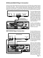
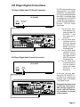
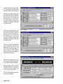
DVD Audio/SACD Player Connection
The Out of the Box input configuration also has provisions for a DVD Player that is capable of playing
DVD Audio and/or SACD. These multi-channel high-resolution discs are designed to offer superior
sound quality. Because of concerns regarding copy-protection, the decoding of the material actually
takes place in the DVD player. For this reason, DVD Audio and SACD players feature six channel
analog audio outputs which are labeled left, center, right, left surround, right surround and subwoofer.
DVD Player with DVD Audio and/or SACD Output
PCM/AC-3/DTS Video
Digital Out
Out
Multi-Channel Output
L C R LS RS Sub
S-Video
Out
The Cinema Reference Mach
II features a DB-25 multi-pin
connection for the six channel
high-resolution audio input.
This standardized jack permits
connection to a DVD or SACD
player’s using a multi-channel
RCA (male) to DB-25 (male)
interconnect cable. This cable
is readily available by several
cable manufacturers.
Component Video Output
Y
Cr
Cb
6 Channel RCA to DB-25
Multi-Channel Audio Cable
(Not included with Cinema Referenceand
typically not included with DVD Player)
"Dolby", "Pro Logic", & the double-D Symbol are trademarks of Dolby Laboratories. All rights reserved.
Manufactured under license from Digital Theater Systems, Inc. US Pat. No. 5,451,942, 5,956,764, 5,974,380, 5,978,762 and other worldwide
patents issued and pending. "DTS", "DTS-ES Extended Surround", and "Neo 6" are trademarks of Digital Theater Systems, Inc. ' 1996,
2000 Digital Theater Systems, Inc. All rights reserved.
Manufactured under license from Lucasfilm Ltd. U.S. patent numbers 5,043,970; 5,189,703; and/or 5,222,059. European patent number
0323830. Other U.S. and foreign patents pending. Lucasfilm and THX are trademarks or registered trademarks of Lucasfilm Ltd. Surround
EX is a jointly developed technology of THX and Dolby Laboratories, Inc., and is a trademark of Dolby. Used under authorization.
VGA¥RGBHV¥HDTV INPUTS
2
3
PROCESSED
VIDEO INPUTS
3
5
1
VIDEO OUT
1
REC
7
1
VGA ONLY
COMPOSITE & S-VIDEO
ARE UP-CONVERTED &
LINE-DOUBLED
8 CHANNEL DB-25 INPUT
13
1
25 14
PIN
POINTS
Y
MULTI-PIN LFE SUM
0dB
+10dB
PB/B-Y
COMPONENT VIDEO
Y
PB/B-Y
PR/R-Y
PR/R-Y
6
8
2
REC
OSD
L
L
2
1
SBL
L
3
4
1
3
7
6
R
CAUTION
RISK OF ELECTRIC SHOCK
DO NOT OPEN
ATTENTION!
RISQUE DE CHOC ELECTRIQUE.
NE PAS OUVRIR
R
PB
1
Y
DIGITAL AUDIO
INPUTS
OPTICAL INPUTS
C
PR
3
DATA PORT 12VDC OUT
Serial Data
115 V
115V
R
SBR
AUDIO INPUTS
RS
R
SUB
1
3
2
2
4
AC OUTPUT
4
Voltage
Selector &
Safety Fuse
On This
Side
100mA Max Per
ADA Bus¤ DC 1 DC 2
1 2 3 4 1- 2+ 1- 2+
MAIN
8
WARNING!
Risk Of Hazardous Energy! Make Proper Connections.
AVERTISSEMENT!
Energie Electrique Dangereuse! Faire Des Connexions Propres
Pour L’Hautparleur. Voir La Notice De Fonctionnement.
CAUTION: Disconnect Supply Cord Before Servicing.
ATTENTION: Debrancher Avant Le Depannage.
L
OUTPUT
L
LS
L
5
R
R
ADA NET“
RECORD
OUT
To listen to DVD Audio or
SACD, select the DVD AUDIO
9 input label. To view normal
DVDs, return to the DVD
PLAYER 1 input label.
CINEMA REFERENCE MACH II
HOME THEATER CONTROLLER
MADE IN U.S.A.
S-VIDEO INPUTS
1
2
4
3
2
4
2
115V~2/10 A.S.B.
230V~1/10 A.S.B.
115V~60Hz/230V~50Hz
PIN +/- CHAN PIN +/- CHAN
1 / 14 LT
7 / 20 SBL
2 / 15 CT
8 / 21 SBR
3 / 16 RT
9 /10/22 SHLD
4 / 17 SB
11 / 23 R.T.A
5 / 18 SL
12 / 24 R.T.B
6 / 19 SR
13 / 25 R.T.C
MAIN
VGASWITCHER
AC VOLTAGE
4
115 V
VGA¥RGB¥HDTV OUTPUT
GND OUT IN 12VDC
AC INPUT
10A~ Max Switched 115V~60Hz/230V~50Hz
230V
Use Same
Value Fuse
115V~1AS.B.
230V~.5AS.B.
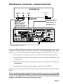
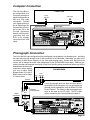
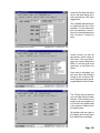
HDTV DVD Player Connection
The Out of the Box input configuration also has provisions
for a DVD Player that is capable of playing HDTV DVDs.
These DVDs provide better
video resolution than standard
DVDs. HDTV DVD players
feature a 15-pin HD/VGA output which is then connected to
the Cinema Reference Mach
II’s HDTV input #1.
HDTV DVD Player
PCM/AC-3/DTS Video
Digital Out
Out
S-Video
Out
HD VGA Output
S-Video Cable
(Primary Video Connection
providing TV has S-Video Input)
Video Cable
(When driving the TV with
S-Video or component
video, this cable is still
required to drive the Cinema
Reference’s LCD display.
HDTV Video
1
"Dolby", "Pro Logic", & the double-D Symbol are trademarks of Dolby Laboratories. All rights reserved.
Manufactured under license from Digital Theater Systems, Inc. US Pat. No. 5,451,942, 5,956,764, 5,974,380, 5,978,762 and other worldwide
patents issued and pending. "DTS", "DTS-ES Extended Surround", and "Neo 6" are trademarks of Digital Theater Systems, Inc. ' 1996,
2000 Digital Theater Systems, Inc. All rights reserved.
Manufactured under license from Lucasfilm Ltd. U.S. patent numbers 5,043,970; 5,189,703; and/or 5,222,059. European patent number
0323830. Other U.S. and foreign patents pending. Lucasfilm and THX are trademarks or registered trademarks of Lucasfilm Ltd. Surround
EX is a jointly developed technology of THX and Dolby Laboratories, Inc., and is a trademark of Dolby. Used under authorization.
VGA¥RGBHV¥HDTV INPUTS
2
3
PROCESSED
1
VIDEO INPUTS
3
5
1
COMPOSITE & S-VIDEO
ARE UP-CONVERTED &
LINE-DOUBLED
VIDEO OUT
1
REC
7
PIN +/- CHAN PIN +/- CHAN
1 / 14 LT
7 / 20 SBL
2 / 15 CT
8 / 21 SBR
3 / 16 RT
9 /10/22 SHLD
4 / 17 SB
11 / 23 R.T.A
5 / 18 SL
12 / 24 R.T.B
6 / 19 SR
13 / 25 R.T.C
VGASWITCHER
AC VOLTAGE
4
8 CHANNEL DB-25 INPUT
13
1
25 14
1
Y
COMPONENT VIDEO
Y
PB/B-Y
PB/B-Y
PR/R-Y
PR/R-Y
6
8
2
R
OSD
L
L
1
2
3
SBL
L
4
5
R
1
3
AUDIO INPUTS
L
LS
7
CAUTION
RISK OF ELECTRIC SHOCK
DO NOT OPEN
ATTENTION!
RISQUE DE CHOC ELECTRIQUE.
NE PAS OUVRIR
R
Y
DIGITAL AUDIO
INPUTS
OPTICAL INPUTS
PB
1
PR
3
DATA PORT 12VDC OUT
Serial Data
115 V
115V
R
SBR
RS
R
SUB
1
2
3
4
Digital Output
(This cable carries Dolby Digital (AC-3) and DTS 6 channel audio from
DVDs and standard 2 channel digital audio from CDs.)
1
2
4
AC OUTPUT
GND OUT IN 12VDC
Voltage
Selector &
Safety Fuse
On This
Side
100mA Max Per
ADA Bus¤ DC 1 DC 2
1 2 3 4 1- 2+ 1- 2+
MAIN
8
WARNING!
Risk Of Hazardous Energy! Make Proper Connections.
AVERTISSEMENT!
Energie Electrique Dangereuse! Faire Des Connexions Propres
Pour L’Hautparleur. Voir La Notice De Fonctionnement.
CAUTION: Disconnect Supply Cord Before Servicing.
ATTENTION: Debrancher Avant Le Depannage.
L
OUTPUT
C
L
6
R
RECORD
OUT
CINEMA REFERENCE MACH II
HOME THEATER CONTROLLER
ADA NET“
MADE IN U.S.A.
S-VIDEO INPUTS
1
2
4
3
REC
PIN
POINTS
2
4
2
115V~2/10 A.S.B.
230V~1/10 A.S.B.
115V~60Hz/230V~50Hz
MULTI-PIN LFE SUM
0dB
+10dB
MAIN
1
VGA ONLY
115 V
VGA¥RGB¥HDTV OUTPUT
AC INPUT
10A~ Max Switched 115V~60Hz/230V~50Hz
230V
Use Same
Value Fuse
115V~1AS.B.
230V~.5AS.B.
Please note, while the diagram
does not show the component
video connection as illustrated
on the previous page, you will
still want to make these connections to provide the best
video resolution for standard
DVDs. At the time of this printing, HDTV DVD players are
not yet available and as such,
ADA cannot confirm that these
players will internally up-convert component video to VGA.
Page 13
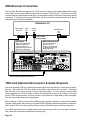
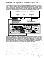
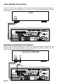
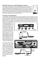
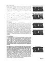
DSS Receiver Connection
The Out of the Box input configuration for a DSS receiver is set to use the optical digital audio output
of the DSS receiver as most DSS receivers have this type of TOS-Link jack. In the event your DSS
receiver features a digital audio coaxial jack, you may wish to use this connection instead of the optical
connection. Coaxial connections are better than optical connections, especially when basic optical
interconnects are all that are available.
DSS/SATELLITE
Opitcal Digital
Audio Out
Video
Out
S-Video
Output
HD VGA Output
S-Video Cable
(Primary Video)
Video Cable
HDTV Video (Optional)
(When driving the TV with
S-Video or component
video, this cable is still
required to drive the Cinema
Reference’s LCD display.
(You must connect this
cable to a TV, linedoubler, or projector that
is capable of processing
HDTV (VGA) video)
2
VGA¥RGBHV¥HDTV INPUTS
2
3
VGA¥RGB¥HDTV OUTPUT
PROCESSED
VIDEO INPUTS
3
5
2
1
COMPOSITE & S-VIDEO
ARE UP-CONVERTED &
LINE-DOUBLED
VIDEO OUT
1
REC
7
PIN +/- CHAN PIN +/- CHAN
1 / 14 LT
7 / 20 SBL
2 / 15 CT
8 / 21 SBR
3 / 16 RT
9 /10/22 SHLD
4 / 17 SB
11 / 23 R.T.A
5 / 18 SL
12 / 24 R.T.B
6 / 19 SR
13 / 25 R.T.C
VGASWITCHER
AC VOLTAGE
4
8 CHANNEL DB-25 INPUT
2
13
1
25 14
PIN
POINTS
Y
PB/B-Y
COMPONENT VIDEO
Y
PR/R-Y
PB/B-Y
PR/R-Y
6
8
1
REC
2
R
OSD
L
L
1
2
3
S-VIDEO INPUTS
2
4
3
SBL
L
4
5
R
1
3
AUDIO INPUTS
7
ADA NET“
CAUTION
RISK OF ELECTRIC SHOCK
DO NOT OPEN
ATTENTION!
RISQUE DE CHOC ELECTRIQUE.
NE PAS OUVRIR
L
LS
R
C
Y
DIGITAL AUDIO
INPUTS
OPTICAL INPUTS
PB
1
PR
3
DATA PORT 12VDC OUT
Serial Data
115 V
115V
R
SBR
RS
R
SUB
1
2
3
4
2
4
AC OUTPUT
GND OUT IN 12VDC
Voltage
Selector &
Safety Fuse
On This
Side
100mA Max Per
ADA Bus¤ DC 1 DC 2
1 2 3 4 1- 2+ 1- 2+
MAIN
8
WARNING!
Risk Of Hazardous Energy! Make Proper Connections.
AVERTISSEMENT!
Energie Electrique Dangereuse! Faire Des Connexions Propres
Pour L’Hautparleur. Voir La Notice De Fonctionnement.
CAUTION: Disconnect Supply Cord Before Servicing.
ATTENTION: Debrancher Avant Le Depannage.
L
OUTPUT
L
6
R
RECORD
OUT
CINEMA REFERENCE MACH II
HOME THEATER CONTROLLER
MADE IN U.S.A.
2
4
2
115V~2/10 A.S.B.
230V~1/10 A.S.B.
115V~60Hz/230V~50Hz
MULTI-PIN LFE SUM
0dB
+10dB
MAIN
1
VGA ONLY
115 V
"Dolby", "Pro Logic", & the double-D Symbol are trademarks of Dolby Laboratories. All rights reserved.
Manufactured under license from Digital Theater Systems, Inc. US Pat. No. 5,451,942, 5,956,764, 5,974,380, 5,978,762 and other worldwide
patents issued and pending. "DTS", "DTS-ES Extended Surround", and "Neo 6" are trademarks of Digital Theater Systems, Inc. ' 1996,
2000 Digital Theater Systems, Inc. All rights reserved.
Manufactured under license from Lucasfilm Ltd. U.S. patent numbers 5,043,970; 5,189,703; and/or 5,222,059. European patent number
0323830. Other U.S. and foreign patents pending. Lucasfilm and THX are trademarks or registered trademarks of Lucasfilm Ltd. Surround
EX is a jointly developed technology of THX and Dolby Laboratories, Inc., and is a trademark of Dolby. Used under authorization.
AC INPUT
10A~ Max Switched 115V~60Hz/230V~50Hz
230V
Use Same
Value Fuse
115V~1AS.B.
230V~.5AS.B.
2
TOS-Link Optical Digital Interconnect
TOS-Link Optical Interconnects & Audio Dropouts
The issue regarding TOS-Link optical interconnects stems from the manner in which they are manufactured. The most basic TOS-Link cables have the fiber optic line cut with a hot wire. Cutting the
fiber optic line in this manner forms a smooth reflective surface. It is this reflective surface which
causes digital data, in the form of light, to reflect off of the optical receiver, and in essence, back feed
into the TOS-Link interconnect. As such, the flow of light (the flow of digital data) is then interrupted.
This will cause audio dropouts during playback.
When selecting a TOS-Link interconnect, ADA strongly suggests using the very best cable available.
Typically, these cables offer some type of frosted tip which greatly reduces the reflective interference.
The very best TOS-Link interconnects provide convex tips which eliminate reflective interference.
If your DSS receiver features a digital coaxial audio output and you wish to use this type of interconnect, follow the instructions as outlined on the next page.
Page 14
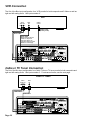
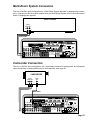
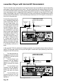
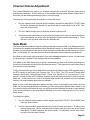
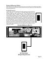
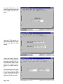
DSS Receiver Connection - Coaxial Connection
DSS/SATELLITE
Digital
Audio Out
Video
Out
S-Video
Output
HD VGA Output
S-Video Cable
(Primary Video)
HDTV Video (Optional)
(You must connect this
cable to a TV, linedoubler, or projector that
is capable of processing
HDTV (VGA) video)
Video Cable
(When driving the TV with
S-Video or component
video, this cable is still
required to drive the Cinema
Reference’s LCD display.
2
VGA¥RGBHV¥HDTV INPUTS
2
3
VGA¥RGB¥HDTV OUTPUT
PROCESSED
VIDEO INPUTS
3
5
2
1
COMPOSITE & S-VIDEO
ARE UP-CONVERTED &
LINE-DOUBLED
VIDEO OUT
1
REC
7
PIN +/1 / 14
2 / 15
3 / 16
4 / 17
5 / 18
6 / 19
CHAN PIN +/- CHAN
LT
7 / 20 SBL
CT
8 / 21 SBR
RT
9 /10/22 SHLD
SB
11 / 23 R.T.A
SL
12 / 24 R.T.B
SR
13 / 25 R.T.C
VGASWITCHER
AC VOLTAGE
4
8 CHANNEL DB-25 INPUT
2
13
1
25 14
PIN
POINTS
Y
PB/B-Y
COMPONENT VIDEO
Y
PB/B-Y
PR/R-Y
PR/R-Y
6
8
1
REC
2
R
OSD
L
L
1
2
3
S-VIDEO INPUTS
2
4
3
SBL
L
4
5
3
R
R
AUDIO INPUTS
7
ADA NET“
CAUTION
RISK OF ELECTRIC SHOCK
DO NOT OPEN
ATTENTION!
RISQUE DE CHOC ELECTRIQUE.
NE PAS OUVRIR
L
LS
R
C
Y
DIGITAL AUDIO
INPUTS
OPTICAL INPUTS
PB
1
PR
3
DATA PORT 12VDC OUT
Serial Data
115 V
115V
R
SBR
RS
R
SUB
1
2
3
4
2
4
AC OUTPUT
GND OUT IN 12VDC
Voltage
Selector &
Safety Fuse
On This
Side
100mA Max Per
ADA Bus¤ DC 1 DC 2
1 2 3 4 1- 2+ 1- 2+
MAIN
8
WARNING!
Risk Of Hazardous Energy! Make Proper Connections.
AVERTISSEMENT!
Energie Electrique Dangereuse! Faire Des Connexions Propres
Pour L’Hautparleur. Voir La Notice De Fonctionnement.
CAUTION: Disconnect Supply Cord Before Servicing.
ATTENTION: Debrancher Avant Le Depannage.
L
OUTPUT
L
6
RECORD
OUT
CINEMA REFERENCE MACH II
HOME THEATER CONTROLLER
MADE IN U.S.A.
1
2
4
2
115V~2/10 A.S.B.
230V~1/10 A.S.B.
115V~60Hz/230V~50Hz
MULTI-PIN LFE SUM
0dB
+10dB
MAIN
1
VGA ONLY
115 V
"Dolby", "Pro Logic", & the double-D Symbol are trademarks of Dolby Laboratories. All rights reserved.
Manufactured under license from Digital Theater Systems, Inc. US Pat. No. 5,451,942, 5,956,764, 5,974,380, 5,978,762 and other worldwide
patents issued and pending. "DTS", "DTS-ES Extended Surround", and "Neo 6" are trademarks of Digital Theater Systems, Inc. ' 1996,
2000 Digital Theater Systems, Inc. All rights reserved.
Manufactured under license from Lucasfilm Ltd. U.S. patent numbers 5,043,970; 5,189,703; and/or 5,222,059. European patent number
0323830. Other U.S. and foreign patents pending. Lucasfilm and THX are trademarks or registered trademarks of Lucasfilm Ltd. Surround
EX is a jointly developed technology of THX and Dolby Laboratories, Inc., and is a trademark of Dolby. Used under authorization.
AC INPUT
10A~ Max Switched 115V~60Hz/230V~50Hz
230V
Use Same
Value Fuse
115V~1AS.B.
230V~.5AS.B.
2
Coaxial Digital Interconnect
In the event that the DSS receiver features a coaxial digital audio output which you intend to use
instead of the TOS-Link output, you will need to connect a 75Ω interconnect to Digital Input #2. When
doing this, you will also need to change the audio jack assigned to the DSS input label. To do this:
1
Turn the input knob until display’s second line reads DSS 2 and then press the Input knob.
2
Turn the Mode knob clockwise until the display’s second line reads SETUP MENU and press
the Mode knob.
3
Turn the Mode knob clockwise until the display’s second line reads AUDIO INPUTS and press
the Mode knob.
4
Turn the Mode knob clockwise until the display’s second line reads DIGITAL 2.
At this time, you have reassigned the DSS 2 input label from tracking the Optical 2 input to the Digital
2 input.
Please note that regardless of which wiring option you choose to use when connecting a DSS
receiver to the Cinema Reference Mach II, you may still need to make adjustments to the DSS
receiver. As many DSS receivers have multiple audio output setup configurations, ADA strongly
suggests reviewing the DSS manual to insure proper setup.
Page 15
DVR/PVR Connection
The Out of the Box input configuration for a DVR (Digital Video Recorder) are sometimes called PVRs
(Personal Video Recorders). There are several different models available and the diagram below
shows connection of the most basic type of models.
These units feature analog audio outputs along with both composite video and S-Video outputs. The
diagram to the right details the connection of more advanced models that in addition to the outputs
found on standard models, also include a digital audio output as well as a VGA video output. Because
the Cinema Reference Mach II’s Out of the Box setup is designed for easy connection of all types of
DVRs, the diagram below shows the more basic connection. To alter the Cinema Reference’s input
configuration for DVR’s with digital audio, follow the instructions on the next page.
DVR / PVR
Stereo
Audio Out
R
Video
Out
S-Video
Output
L
S-Video Cable
(Primary Video)
Audio Cable
Video Cable
(When driving the TV with
S-Video or component
video, this cable is still
required to drive the Cinema
Reference’s LCD display.
"Dolby", "Pro Logic", & the double-D Symbol are trademarks of Dolby Laboratories. All rights reserved.
Manufactured under license from Digital Theater Systems, Inc. US Pat. No. 5,451,942, 5,956,764, 5,974,380, 5,978,762 and other worldwide
patents issued and pending. "DTS", "DTS-ES Extended Surround", and "Neo 6" are trademarks of Digital Theater Systems, Inc. ' 1996,
2000 Digital Theater Systems, Inc. All rights reserved.
Manufactured under license from Lucasfilm Ltd. U.S. patent numbers 5,043,970; 5,189,703; and/or 5,222,059. European patent number
0323830. Other U.S. and foreign patents pending. Lucasfilm and THX are trademarks or registered trademarks of Lucasfilm Ltd. Surround
EX is a jointly developed technology of THX and Dolby Laboratories, Inc., and is a trademark of Dolby. Used under authorization.
VGA¥RGBHV¥HDTV INPUTS
2
3
COMPOSITE & S-VIDEO
ARE UP-CONVERTED &
LINE-DOUBLED
VIDEO INPUTS
3
5
1
VIDEO OUT
1
REC
7
PIN +/1 / 14
2 / 15
3 / 16
4 / 17
5 / 18
6 / 19
CHAN PIN +/- CHAN
LT
7 / 20 SBL
CT
8 / 21 SBR
RT
9 /10/22 SHLD
SB
11 / 23 R.T.A
SL
12 / 24 R.T.B
SR
13 / 25 R.T.C
VGASWITCHER
AC VOLTAGE
4
8 CHANNEL DB-25 INPUT
3
13
1
25 14
PIN
POINTS
Y
PB/B-Y
COMPONENT VIDEO
Y
PB/B-Y
PR/R-Y
PR/R-Y
4
L
1
3
3
R
6
8
2
1
REC
OSD
L
2
3
S-VIDEO INPUTS
2
4
3
SBL
L
4
5
1
3
R
R
AUDIO INPUTS
7
ADA NET“
CAUTION
RISK OF ELECTRIC SHOCK
DO NOT OPEN
ATTENTION!
RISQUE DE CHOC ELECTRIQUE.
NE PAS OUVRIR
L
LS
R
C
Y
DIGITAL AUDIO
INPUTS
OPTICAL INPUTS
PB
1
PR
3
DATA PORT 12VDC OUT
Serial Data
115 V
115V
R
SBR
RS
R
SUB
1
2
3
4
2
4
AC OUTPUT
GND OUT IN 12VDC
Voltage
Selector &
Safety Fuse
On This
Side
100mA Max Per
ADA Bus¤ DC 1 DC 2
1 2 3 4 1- 2+ 1- 2+
MAIN
8
WARNING!
Risk Of Hazardous Energy! Make Proper Connections.
AVERTISSEMENT!
Energie Electrique Dangereuse! Faire Des Connexions Propres
Pour L’Hautparleur. Voir La Notice De Fonctionnement.
CAUTION: Disconnect Supply Cord Before Servicing.
ATTENTION: Debrancher Avant Le Depannage.
L
OUTPUT
L
6
RECORD
OUT
CINEMA REFERENCE MACH II
HOME THEATER CONTROLLER
MADE IN U.S.A.
2
2
115V~2/10 A.S.B.
230V~1/10 A.S.B.
115V~60Hz/230V~50Hz
MULTI-PIN LFE SUM
0dB
+10dB
MAIN
1
VGA ONLY
115 V
VGA¥RGB¥HDTV OUTPUT
PROCESSED
3
AC INPUT
10A~ Max Switched 115V~60Hz/230V~50Hz
230V
Use Same
Value Fuse
115V~1AS.B.
230V~.5AS.B.
DVRs are designed to record material that is being broadcast (either off-air TV, cable TV, or DSS TV)
and may require an output from a broadcast tuner to permit this recording function. Some units
feature an internal tuning device of their own. As such, you may be able to record into the DVR while
you watch something else. To maximize the connectivity of your DVR and the Cinema Reference
Mach II, you will need to consult with the DVR’s instruction manual regarding connecting other devices to the DVR. Please note, that you may wish to connect some components to both the DVR and
the Cinema Reference.
Page 16
DVR/PVR with Digtial Audio & VGA Video Connection
The Out of the Box input configuration for a DVR provides for analog audio connections. This configuration, in addition to composite video and S-Video, is also setup for VGA video. As such, if you are
using an advanced DVR, one that also features a VGA video output (i.e. replay tv 4000), you can
connect this output to the Cinema Reference’s #3 VGA input. As with other components that feature
a VGA output, this connection is only useful if your display device features a VGA/HDTV input.
DVR/PVR with Digital Audio & VGA Video
S-Video
Output
Opitcal Digital Video
Stereo
Audio Out
Audio Out
Out
R
HD VGA Output
L
S-Video Cable
(Primary Video)
Video Cable
HDTV Video (Optional)
(This cable is required to
drive the LCD display.)
3
VGA¥RGBHV¥HDTV INPUTS
2
3
VGA¥RGB¥HDTV OUTPUT
PROCESSED
COMPOSITE & S-VIDEO
ARE UP-CONVERTED &
LINE-DOUBLED
3
VIDEO INPUTS
5
3
1
VIDEO OUT
REC
1
7
PIN +/- CHAN PIN +/- CHAN
1 / 14 LT
7 / 20 SBL
2 / 15 CT
8 / 21 SBR
3 / 16 RT
9 /10/22 SHLD
4 / 17 SB
11 / 23 R.T.A
5 / 18 SL
12 / 24 R.T.B
6 / 19 SR
13 / 25 R.T.C
VGASWITCHER
AC VOLTAGE
4
8 CHANNEL DB-25 INPUT
3
13
1
25 14
PIN
POINTS
Y
PB/B-Y
COMPONENT VIDEO
Y
PB/B-Y
PR/R-Y
PR/R-Y
1
REC
L
L
2
1
R
OSD
2
8
6
4
S-VIDEO INPUTS
2
4
3
SBL
L
4
3
1
3
R
R
AUDIO INPUTS
7
ADA NET“
CAUTION
RISK OF ELECTRIC SHOCK
DO NOT OPEN
ATTENTION!
RISQUE DE CHOC ELECTRIQUE.
NE PAS OUVRIR
L
LS
R
C
Y
DIGITAL AUDIO
INPUTS
OPTICAL INPUTS
PB
1
PR
3
DATA PORT 12VDC OUT
Serial Data
115 V
115V
R
SBR
RS
R
SUB
1
2
3
4
2
4
AC OUTPUT
GND OUT IN 12VDC
Voltage
Selector &
Safety Fuse
On This
Side
100mA Max Per
ADA Bus¤ DC 1 DC 2
1 2 3 4 1- 2+ 1- 2+
MAIN
8
WARNING!
Risk Of Hazardous Energy! Make Proper Connections.
AVERTISSEMENT!
Energie Electrique Dangereuse! Faire Des Connexions Propres
Pour L’Hautparleur. Voir La Notice De Fonctionnement.
CAUTION: Disconnect Supply Cord Before Servicing.
ATTENTION: Debrancher Avant Le Depannage.
L
OUTPUT
L
6
5
RECORD
OUT
CINEMA REFERENCE MACH II
HOME THEATER CONTROLLER
MADE IN U.S.A.
2
2
115V~2/10 A.S.B.
230V~1/10 A.S.B.
115V~60Hz/230V~50Hz
MULTI-PIN LFE SUM
0dB
+10dB
MAIN
1
VGA ONLY
115 V
"Dolby", "Pro Logic", & the double-D Symbol are trademarks of Dolby Laboratories. All rights reserved.
Manufactured under license from Digital Theater Systems, Inc. US Pat. No. 5,451,942, 5,956,764, 5,974,380, 5,978,762 and other worldwide
patents issued and pending. "DTS", "DTS-ES Extended Surround", and "Neo 6" are trademarks of Digital Theater Systems, Inc. ' 1996,
2000 Digital Theater Systems, Inc. All rights reserved.
Manufactured under license from Lucasfilm Ltd. U.S. patent numbers 5,043,970; 5,189,703; and/or 5,222,059. European patent number
0323830. Other U.S. and foreign patents pending. Lucasfilm and THX are trademarks or registered trademarks of Lucasfilm Ltd. Surround
EX is a jointly developed technology of THX and Dolby Laboratories, Inc., and is a trademark of Dolby. Used under authorization.
AC INPUT
10A~ Max Switched 115V~60Hz/230V~50Hz
230V
Use Same
Value Fuse
115V~1AS.B.
230V~.5AS.B.
3
Regardless of whether your display device features a VGA/HDTV input, the advanced DVRs also
offer a digital audio output that will improve your entertainment experience. Because the Out of the
Box configuration defaults to the Analog 3 input, you will first need to reassign the DVR/PVR input
label to a digital audio jack. At the time of this printing, advanced DVRs feature a TOS-Link optical
digital connection which should be connected to the Cinema Reference Mach II’s Optical Input #3. To
reassign the DVR/PVR input label to track the digital input, follow the steps below.
1
2
3
4
Turn the input knob until display’s second line reads DVR/PVR 3 and then press the Input
knob.
Turn the Mode knob clockwise until the display’s second line reads SETUP MENU and press
the Mode knob.
Turn the Mode knob clockwise until the display’s second line reads AUDIO INPUTS and press
the Mode knob.
Turn the Mode knob counterclockwise until the display’s second line reads OPTICAL 3.
At this time, you have reassigned the DVR/PVR 3 input label from tracking the Analog 3 input to the
Optical 3 input.
Please note that when using a TOS-Link interconnect, ADA strongly suggests using the very
best interconnect available to prevent audio dropouts.
Page 17
VCR Connection
The Out of the Box input configuration for a VCR permits for both composite and S-Video as well as
right and left analog audio. Use inputs number 4.
VCR
Stereo
Audio Out
R
Video
Out
S-Video
Output
L
S-Video Cable
(Primary Video)
Audio Cable
Video Cable
(When driving the TV with
S-Video or component
video, this cable is still
required to drive the Cinema
Reference’s LCD display.
"Dolby", "Pro Logic", & the double-D Symbol are trademarks of Dolby Laboratories. All rights reserved.
Manufactured under license from Digital Theater Systems, Inc. US Pat. No. 5,451,942, 5,956,764, 5,974,380, 5,978,762 and other worldwide
patents issued and pending. "DTS", "DTS-ES Extended Surround", and "Neo 6" are trademarks of Digital Theater Systems, Inc. ' 1996,
2000 Digital Theater Systems, Inc. All rights reserved.
Manufactured under license from Lucasfilm Ltd. U.S. patent numbers 5,043,970; 5,189,703; and/or 5,222,059. European patent number
0323830. Other U.S. and foreign patents pending. Lucasfilm and THX are trademarks or registered trademarks of Lucasfilm Ltd. Surround
EX is a jointly developed technology of THX and Dolby Laboratories, Inc., and is a trademark of Dolby. Used under authorization.
VGA¥RGBHV¥HDTV INPUTS
2
3
VIDEO INPUTS
3
5
4
1
13
1
25 14
8 CHANNEL DB-25 INPUT
4
MULTI-PIN LFE SUM
0dB
+10dB
MAIN
VGASWITCHER
AC VOLTAGE
4
PIN
POINTS
Y
PB/B-Y
COMPONENT VIDEO
Y
PB/B-Y
PR/R-Y
6
L
2
1
R
4
4
8
2
1
REC
1
S-VIDEO INPUTS
2
4
3
SBL
L
4
3
7
6
R
ATTENTION!
R
L
LS
PB
1
Y
DIGITAL AUDIO
INPUTS
OPTICAL INPUTS
C
PR
3
DATA PORT 12VDC OUT
115 V
115V
R
SBR
AUDIO INPUTS
RS
R
SUB
1
3
2
4
2
AC OUTPUT
4
Voltage
Selector &
Safety Fuse
On This
Side
100mA Max Per
Serial Data
ADA Bus¤ DC 1 DC 2
1 2 3 4 1- 2+ 1- 2+
MAIN
8
WARNING!
Risk Of Hazardous Energy! Make Proper Connections.
AVERTISSEMENT!
Energie Electrique Dangereuse! Faire Des Connexions Propres
Pour L’Hautparleur. Voir La Notice De Fonctionnement.
CAUTION: Disconnect Supply Cord Before Servicing.
ATTENTION: Debrancher Avant Le Depannage.
L
OUTPUT
L
5
R
CAUTION
RISK OF ELECTRIC SHOCK
DO NOT OPEN
RISQUE DE CHOC ELECTRIQUE.
NE PAS OUVRIR
MADE IN U.S.A.
OSD
L
3
CINEMA REFERENCE MACH II
HOME THEATER CONTROLLER
ADA NET“
RECORD
OUT
PR/R-Y
2
4
2
115V~2/10 A.S.B.
230V~1/10 A.S.B.
115V~60Hz/230V~50Hz
PIN +/- CHAN PIN +/- CHAN
1 / 14 LT
7 / 20 SBL
2 / 15 CT
8 / 21 SBR
3 / 16 RT
9 /10/22 SHLD
4 / 17 SB
11 / 23 R.T.A
5 / 18 SL
12 / 24 R.T.B
6 / 19 SR
13 / 25 R.T.C
VIDEO OUT
1
REC
7
1
VGA ONLY
COMPOSITE & S-VIDEO
ARE UP-CONVERTED &
LINE-DOUBLED
115 V
VGA¥RGB¥HDTV OUTPUT
PROCESSED
GND OUT IN 12VDC
AC INPUT
10A~ Max Switched 115V~60Hz/230V~50Hz
230V
Use Same
Value Fuse
115V~1AS.B.
230V~.5AS.B.
Cable or TV Tuner Connection
The Out of the Box input configuration for a Cable TV box or TV tuner permits for both composite and
right and left analog audio. Use inputs number 5. For advanced tuners, see the next page.
CABLE/TV TUNER
Stereo
Audio Out
R
Video
Out
L
Audio Cable
Video Cable
"Dolby", "Pro Logic", & the double-D Symbol are trademarks of Dolby Laboratories. All rights reserved.
Manufactured under license from Digital Theater Systems, Inc. US Pat. No. 5,451,942, 5,956,764, 5,974,380, 5,978,762 and other worldwide
patents issued and pending. "DTS", "DTS-ES Extended Surround", and "Neo 6" are trademarks of Digital Theater Systems, Inc. ' 1996,
2000 Digital Theater Systems, Inc. All rights reserved.
Manufactured under license from Lucasfilm Ltd. U.S. patent numbers 5,043,970; 5,189,703; and/or 5,222,059. European patent number
0323830. Other U.S. and foreign patents pending. Lucasfilm and THX are trademarks or registered trademarks of Lucasfilm Ltd. Surround
EX is a jointly developed technology of THX and Dolby Laboratories, Inc., and is a trademark of Dolby. Used under authorization.
VGA¥RGBHV¥HDTV INPUTS
2
3
COMPOSITE & S-VIDEO
ARE UP-CONVERTED &
LINE-DOUBLED
VIDEO INPUTS
3
5
1
VIDEO OUT
1
REC
7
1
VGA ONLY
PIN +/- CHAN PIN +/- CHAN
1 / 14 LT
7 / 20 SBL
2 / 15 CT
8 / 21 SBR
3 / 16 RT
9 /10/22 SHLD
4 / 17 SB
11 / 23 R.T.A
5 / 18 SL
12 / 24 R.T.B
6 / 19 SR
13 / 25 R.T.C
13
1
25 14
PIN
POINTS
Y
PB/B-Y
COMPONENT VIDEO
Y
PB/B-Y
PR/R-Y
PR/R-Y
4
6
8
1
REC
2
R
5
5
OSD
L
L
1
2
3
S-VIDEO INPUTS
2
4
3
5
AUDIO INPUTS
Page 18
SBL
L
4
R
1
3
7
ADA NET“
CAUTION
RISK OF ELECTRIC SHOCK
DO NOT OPEN
ATTENTION!
RISQUE DE CHOC ELECTRIQUE.
NE PAS OUVRIR
L
LS
R
C
Y
DIGITAL AUDIO
INPUTS
OPTICAL INPUTS
PB
1
PR
3
DATA PORT 12VDC OUT
Serial Data
115 V
115V
R
SBR
RS
R
SUB
1
2
3
4
2
4
AC OUTPUT
GND OUT IN 12VDC
Voltage
Selector &
Safety Fuse
On This
Side
100mA Max Per
ADA Bus¤ DC 1 DC 2
1 2 3 4 1- 2+ 1- 2+
MAIN
8
WARNING!
Risk Of Hazardous Energy! Make Proper Connections.
AVERTISSEMENT!
Energie Electrique Dangereuse! Faire Des Connexions Propres
Pour L’Hautparleur. Voir La Notice De Fonctionnement.
CAUTION: Disconnect Supply Cord Before Servicing.
ATTENTION: Debrancher Avant Le Depannage.
L
OUTPUT
L
6
R
RECORD
OUT
CINEMA REFERENCE MACH II
HOME THEATER CONTROLLER
MADE IN U.S.A.
2
2
115V~2/10 A.S.B.
230V~1/10 A.S.B.
115V~60Hz/230V~50Hz
8 CHANNEL DB-25 INPUT
MULTI-PIN LFE SUM
0dB
+10dB
MAIN
VGASWITCHER
AC VOLTAGE
4
115 V
VGA¥RGB¥HDTV OUTPUT
PROCESSED
5
AC INPUT
10A~ Max Switched 115V~60Hz/230V~50Hz
230V
Use Same
Value Fuse
115V~1AS.B.
230V~.5AS.B.
Digital or HDTV Cable/TV Tuner Connection
The Out of the Box input configuration for Cable/TV tuners provides for analog audio connections
along with composite video. If you are using a HDTV tuner instead of a cable TV tuner, you will need
to alternate the audio input configuration for the CABLE/TV 5 input label. This input label is also setup
Out of the Box for a VGA/HDTV input on VGA input #4. To permit the Cinema Reference Mach II to
play digital audio, you will need to connect a TOS-Link interconnect between your tuning device and
the Cinema Reference’s #4 optical input.
HDTV CABLE/TV TUNER
Stereo
Audio Out
R
Opitcal Digital
Audio Out
Video
Out
HD VGA Output
L
HDTV Video
Video Cable
(This cable is required to
drive the LCD display.)
4
"Dolby", "Pro Logic", & the double-D Symbol are trademarks of Dolby Laboratories. All rights reserved.
Manufactured under license from Digital Theater Systems, Inc. US Pat. No. 5,451,942, 5,956,764, 5,974,380, 5,978,762 and other worldwide
patents issued and pending. "DTS", "DTS-ES Extended Surround", and "Neo 6" are trademarks of Digital Theater Systems, Inc. ' 1996,
2000 Digital Theater Systems, Inc. All rights reserved.
Manufactured under license from Lucasfilm Ltd. U.S. patent numbers 5,043,970; 5,189,703; and/or 5,222,059. European patent number
0323830. Other U.S. and foreign patents pending. Lucasfilm and THX are trademarks or registered trademarks of Lucasfilm Ltd. Surround
EX is a jointly developed technology of THX and Dolby Laboratories, Inc., and is a trademark of Dolby. Used under authorization.
VGA¥RGBHV¥HDTV INPUTS
2
3
PROCESSED
5
VIDEO INPUTS
5
3
1
VIDEO OUT
REC
1
7
PIN +/1 / 14
2 / 15
3 / 16
4 / 17
5 / 18
6 / 19
CHAN PIN +/LT
7 / 20
CT
8 / 21
RT
9 /10/22
SB
11 / 23
SL
12 / 24
SR
13 / 25
1
VGA ONLY
COMPOSITE & S-VIDEO
ARE UP-CONVERTED &
LINE-DOUBLED
CHAN
SBL
SBR
SHLD
R.T.A
R.T.B
R.T.C
8 CHANNEL DB-25 INPUT
13
1
25 14
PIN
POINTS
Y
PB/B-Y
COMPONENT VIDEO
Y
PB/B-Y
PR/R-Y
PR/R-Y
1
REC
S-VIDEO INPUTS
2
4
3
1
3
L
L
2
R
SBL
L
4
3
R
R
AUDIO INPUTS
L
LS
7
CAUTION
RISK OF ELECTRIC SHOCK
DO NOT OPEN
ATTENTION!
RISQUE DE CHOC ELECTRIQUE.
NE PAS OUVRIR
Y
DIGITAL AUDIO
INPUTS
OPTICAL INPUTS
PB
1
PR
3
DATA PORT 12VDC OUT
Serial Data
115 V
115V
R
SBR
RS
R
SUB
1
2
3
4
2
4
AC OUTPUT
GND OUT IN 12VDC
Voltage
Selector &
Safety Fuse
On This
Side
100mA Max Per
ADA Bus¤ DC 1 DC 2
1 2 3 4 1- 2+ 1- 2+
MAIN
8
WARNING!
Risk Of Hazardous Energy! Make Proper Connections.
AVERTISSEMENT!
Energie Electrique Dangereuse! Faire Des Connexions Propres
Pour L’Hautparleur. Voir La Notice De Fonctionnement.
CAUTION: Disconnect Supply Cord Before Servicing.
ATTENTION: Debrancher Avant Le Depannage.
L
R
C
L
6
5
ADA NET“
OUTPUT
2
1
RECORD
OUT
CINEMA REFERENCE MACH II
HOME THEATER CONTROLLER
MADE IN U.S.A.
OSD
2
8
6
4
2
115V~2/10 A.S.B.
230V~1/10 A.S.B.
115V~60Hz/230V~50Hz
MULTI-PIN LFE SUM
0dB
+10dB
MAIN
VGASWITCHER
AC VOLTAGE
4
115 V
VGA¥RGB¥HDTV OUTPUT
AC INPUT
10A~ Max Switched 115V~60Hz/230V~50Hz
230V
Use Same
Value Fuse
115V~1AS.B.
230V~.5AS.B.
4
To reassign the audio input, follow these steps.
1
2
3
4
Turn the input knob until display’s second line reads CABLE/TV 5 and then press the Input
knob.
Turn the Mode knob clockwise until the display’s second line reads SETUP MENU and press
the Mode knob.
Turn the Mode knob clockwise until the display’s second line reads AUDIO INPUTS and press
the Mode knob.
Turn the Mode knob counterclockwise until the display’s second line reads OPTICAL 4.
At this time, you have reassigned the CABLE/TV 5 input label from tracking the Analog 5 input to the
Optical 4 input.
Please note that when using a TOS-Link interconnect, ADA strongly suggests using the very
best interconnect available to prevent audio dropouts.
Page 19
CD Player Connection
The Out of the Box input configuration for CD Player provides for analog audio connections. Connect
your line-level audio outputs from your CD player to the Cinema Reference Mach II’s Analog Audio
input #6.
CD PLAYER
Stereo
Audio Out
R
L
Audio Cable
"Dolby", "Pro Logic", & the double-D Symbol are trademarks of Dolby Laboratories. All rights reserved.
Manufactured under license from Digital Theater Systems, Inc. US Pat. No. 5,451,942, 5,956,764, 5,974,380, 5,978,762 and other worldwide
patents issued and pending. "DTS", "DTS-ES Extended Surround", and "Neo 6" are trademarks of Digital Theater Systems, Inc. ' 1996,
2000 Digital Theater Systems, Inc. All rights reserved.
Manufactured under license from Lucasfilm Ltd. U.S. patent numbers 5,043,970; 5,189,703; and/or 5,222,059. European patent number
0323830. Other U.S. and foreign patents pending. Lucasfilm and THX are trademarks or registered trademarks of Lucasfilm Ltd. Surround
EX is a jointly developed technology of THX and Dolby Laboratories, Inc., and is a trademark of Dolby. Used under authorization.
VGA¥RGBHV¥HDTV INPUTS
2
3
VIDEO INPUTS
3
5
1
COMPOSITE & S-VIDEO
ARE UP-CONVERTED &
LINE-DOUBLED
VIDEO OUT
1
REC
7
PIN +/1 / 14
2 / 15
3 / 16
4 / 17
5 / 18
6 / 19
1
VGA ONLY
CHAN PIN +/- CHAN
LT
7 / 20 SBL
CT
8 / 21 SBR
RT
9 /10/22 SHLD
SB
11 / 23 R.T.A
SL
12 / 24 R.T.B
SR
13 / 25 R.T.C
8 CHANNEL DB-25 INPUT
13
1
25 14
PIN
POINTS
Y
PB/B-Y
COMPONENT VIDEO
Y
PB/B-Y
PR/R-Y
PR/R-Y
6
8
L
L
2
1
R
3
2
6
6
4
R
OSD
S-VIDEO INPUTS
2
4
3
SBL
L
5
1
3
AUDIO INPUTS
R
7
ADA NET“
CAUTION
RISK OF ELECTRIC SHOCK
DO NOT OPEN
ATTENTION!
RISQUE DE CHOC ELECTRIQUE.
NE PAS OUVRIR
L
LS
R
C
Y
DIGITAL AUDIO
INPUTS
OPTICAL INPUTS
PB
1
PR
3
DATA PORT 12VDC OUT
Serial Data
115 V
115V
R
SBR
RS
R
SUB
1
2
3
4
2
4
AC OUTPUT
GND OUT IN 12VDC
Voltage
Selector &
Safety Fuse
On This
Side
100mA Max Per
ADA Bus¤ DC 1 DC 2
1 2 3 4 1- 2+ 1- 2+
MAIN
8
WARNING!
Risk Of Hazardous Energy! Make Proper Connections.
AVERTISSEMENT!
Energie Electrique Dangereuse! Faire Des Connexions Propres
Pour L’Hautparleur. Voir La Notice De Fonctionnement.
CAUTION: Disconnect Supply Cord Before Servicing.
ATTENTION: Debrancher Avant Le Depannage.
L
OUTPUT
L
6
RECORD
OUT
CINEMA REFERENCE MACH II
HOME THEATER CONTROLLER
MADE IN U.S.A.
1
REC
2
4
2
115V~2/10 A.S.B.
230V~1/10 A.S.B.
115V~60Hz/230V~50Hz
MULTI-PIN LFE SUM
0dB
+10dB
MAIN
VGASWITCHER
AC VOLTAGE
4
115 V
VGA¥RGB¥HDTV OUTPUT
PROCESSED
AC INPUT
10A~ Max Switched 115V~60Hz/230V~50Hz
230V
Use Same
Value Fuse
115V~1AS.B.
230V~.5AS.B.
If you are using a CD Player with either TOS-Link Optical or Coaxial digital audio outputs, you can
connect this component to the Cinema Reference Mach II for digital audio playback. When connecting a CD Player to an analog input, the audio signal is first converted to analog internal to the CD
player and then the signal is converted back to digital internal to the Cinema Reference Mach II. As
such, it is best to bypass this down/up conversion by connecting the CD player directly to a digital
input on the Cinema Reference.
To maintain the most flexible Out of the Box setup, ADA suggests using a TOS-Link connection from
the CD Player to the Cinema Reference. In the event, that your CD Player does not feature, a TOSLink Output, you can opt to use one of the four Digital Coaxial inputs on the Cinema Reference,
providing these inputs are not already assigned to other source input labels. You will need to assess
the other connections you have already made, as well as those you will make in the upcoming pages,
to determine which Digital Coaxial input is open. If you have connected a DSS receiver to the Cinema
Reference using a TOS-Link interconnect, then Digital Coaxial Input #2 is available for use with the
CD Player.
Page 20
CD Player Digital Connections
For TOS-Link connections use
Optical Input #1. For Coaxial
connections, use Digital Input
#2 if it is not already assigned
to the DSS. You will also need
to reassign the CD PLAYER
7 input label from Analog Input #6 to the appropriate digital input. To do so, follow
these steps.
CD Player Digital Audio TOS-Link Connection
CD PLAYER
Stereo
Audio Out
R
Opitcal Digital
Audio Out
L
1
"Dolby", "Pro Logic", & the double-D Symbol are trademarks of Dolby Laboratories. All rights reserved.
Manufactured under license from Digital Theater Systems, Inc. US Pat. No. 5,451,942, 5,956,764, 5,974,380, 5,978,762 and other worldwide
patents issued and pending. "DTS", "DTS-ES Extended Surround", and "Neo 6" are trademarks of Digital Theater Systems, Inc. ' 1996,
2000 Digital Theater Systems, Inc. All rights reserved.
Manufactured under license from Lucasfilm Ltd. U.S. patent numbers 5,043,970; 5,189,703; and/or 5,222,059. European patent number
0323830. Other U.S. and foreign patents pending. Lucasfilm and THX are trademarks or registered trademarks of Lucasfilm Ltd. Surround
EX is a jointly developed technology of THX and Dolby Laboratories, Inc., and is a trademark of Dolby. Used under authorization.
VGA¥RGBHV¥HDTV INPUTS
2
3
PROCESSED
VIDEO INPUTS
5
3
1
VIDEO OUT
REC
1
7
1
VGA ONLY
COMPOSITE & S-VIDEO
ARE UP-CONVERTED &
LINE-DOUBLED
13
1
25 14
8 CHANNEL DB-25 INPUT
PIN
POINTS
Y
MULTI-PIN LFE SUM
0dB
+10dB
PB/B-Y
COMPONENT VIDEO
Y
PB/B-Y
PR/R-Y
PR/R-Y
1
REC
S-VIDEO INPUTS
2
4
3
1
3
L
L
SBL
L
R
7
R
CAUTION
2
RISK OF ELECTRIC SHOCK
DO NOT OPEN
ATTENTION!
RISQUE DE CHOC ELECTRIQUE.
NE PAS OUVRIR
PB
1
Y
DIGITAL AUDIO
INPUTS
OPTICAL INPUTS
C
PR
3
DATA PORT 12VDC OUT
ADA Bus¤ DC 1 DC 2
1 2 3 4 1- 2+ 1- 2+
115 V
115V
R
SBR
AUDIO INPUTS
R
RS
SUB
1
2
3
2
4
4
Voltage
Selector &
Safety Fuse
On This
Side
100mA Max Per
Serial Data
MAIN
8
WARNING!
Risk Of Hazardous Energy! Make Proper Connections.
AVERTISSEMENT!
Energie Electrique Dangereuse! Faire Des Connexions Propres
Pour L’Hautparleur. Voir La Notice De Fonctionnement.
CAUTION: Disconnect Supply Cord Before Servicing.
ATTENTION: Debrancher Avant Le Depannage.
L
R
L
LS
L
6
5
4
3
2
R
ADA NET“
RECORD
OUT
OUTPUT
2
1
CINEMA REFERENCE MACH II
HOME THEATER CONTROLLER
MADE IN U.S.A.
OSD
2
8
6
4
2
115V~2/10 A.S.B.
230V~1/10 A.S.B.
115V~60Hz/230V~50Hz
PIN +/- CHAN PIN +/- CHAN
1 / 14 LT
7 / 20 SBL
2 / 15 CT
8 / 21 SBR
3 / 16 RT
9 /10/22 SHLD
4 / 17 SB
11 / 23 R.T.A
5 / 18 SL
12 / 24 R.T.B
6 / 19 SR
13 / 25 R.T.C
MAIN
VGASWITCHER
AC VOLTAGE
4
115 V
VGA¥RGB¥HDTV OUTPUT
AC OUTPUT
GND OUT IN 12VDC
AC INPUT
10A~ Max Switched 115V~60Hz/230V~50Hz
230V
Use Same
Value Fuse
115V~1AS.B.
230V~.5AS.B.
1
3
CD Player Digital Audio Coaxial Connection
4
CD PLAYER
Digital
Audio Out
Stereo
Audio Out
R
L
At this time, you have reassigned the CD PLAYER 7 input label from tracking the
Analog 6 input to the Optical
1 (or Digital 2) input.
"Dolby", "Pro Logic", & the double-D Symbol are trademarks of Dolby Laboratories. All rights reserved.
Manufactured under license from Digital Theater Systems, Inc. US Pat. No. 5,451,942, 5,956,764, 5,974,380, 5,978,762 and other worldwide
patents issued and pending. "DTS", "DTS-ES Extended Surround", and "Neo 6" are trademarks of Digital Theater Systems, Inc. ' 1996,
2000 Digital Theater Systems, Inc. All rights reserved.
Manufactured under license from Lucasfilm Ltd. U.S. patent numbers 5,043,970; 5,189,703; and/or 5,222,059. European patent number
0323830. Other U.S. and foreign patents pending. Lucasfilm and THX are trademarks or registered trademarks of Lucasfilm Ltd. Surround
EX is a jointly developed technology of THX and Dolby Laboratories, Inc., and is a trademark of Dolby. Used under authorization.
VGA¥RGBHV¥HDTV INPUTS
2
3
VIDEO INPUTS
3
5
1
COMPOSITE & S-VIDEO
ARE UP-CONVERTED &
LINE-DOUBLED
VIDEO OUT
1
REC
7
1
VGA ONLY
PIN +/- CHAN PIN +/- CHAN
1 / 14 LT
7 / 20 SBL
2 / 15 CT
8 / 21 SBR
3 / 16 RT
9 /10/22 SHLD
4 / 17 SB
11 / 23 R.T.A
5 / 18 SL
12 / 24 R.T.B
6 / 19 SR
13 / 25 R.T.C
8 CHANNEL DB-25 INPUT
13
1
25 14
PIN
POINTS
Y
PB/B-Y
COMPONENT VIDEO
Y
PB/B-Y
PR/R-Y
PR/R-Y
4
6
8
2
R
OSD
L
L
1
2
3
S-VIDEO INPUTS
2
4
3
SBL
L
4
5
R
1
3
AUDIO INPUTS
7
ADA NET“
CAUTION
RISK OF ELECTRIC SHOCK
DO NOT OPEN
ATTENTION!
RISQUE DE CHOC ELECTRIQUE.
NE PAS OUVRIR
L
LS
R
C
Y
DIGITAL AUDIO
INPUTS
OPTICAL INPUTS
PB
1
PR
3
DATA PORT 12VDC OUT
Serial Data
115 V
115V
R
SBR
RS
R
SUB
1
2
3
4
2
4
AC OUTPUT
GND OUT IN 12VDC
Voltage
Selector &
Safety Fuse
On This
Side
100mA Max Per
ADA Bus¤ DC 1 DC 2
1 2 3 4 1- 2+ 1- 2+
MAIN
8
WARNING!
Risk Of Hazardous Energy! Make Proper Connections.
AVERTISSEMENT!
Energie Electrique Dangereuse! Faire Des Connexions Propres
Pour L’Hautparleur. Voir La Notice De Fonctionnement.
CAUTION: Disconnect Supply Cord Before Servicing.
ATTENTION: Debrancher Avant Le Depannage.
L
OUTPUT
L
6
R
RECORD
OUT
CINEMA REFERENCE MACH II
HOME THEATER CONTROLLER
MADE IN U.S.A.
1
REC
2
2
115V~2/10 A.S.B.
230V~1/10 A.S.B.
115V~60Hz/230V~50Hz
MULTI-PIN LFE SUM
0dB
+10dB
MAIN
VGASWITCHER
AC VOLTAGE
4
115 V
VGA¥RGB¥HDTV OUTPUT
PROCESSED
Turn the input knob
until display’s second line reads CD
PLAYER 7 and
then press the Input knob.
Turn the Mode knob
clockwise until the
display’s second
line reads SETUP
MENU and press
the Mode knob.
Turn the Mode knob
clockwise until the
display’s second
line reads AUDIO
INPUTS and press
the Mode knob.
Turn the Mode knob
counterclockwise
until the display’s
second line reads
OPTICAL 1 (or
DIGITAL 2).
AC INPUT
10A~ Max Switched 115V~60Hz/230V~50Hz
230V
Use Same
Value Fuse
115V~1AS.B.
230V~.5AS.B.
Please note that when using
a TOS-Link interconnect,
ADA strongly suggests using the very best interconnect available to prevent
audio dropouts.
2
Page 21
Tuner (Radio) Connection
The Out of the Box input configuration for a Radio Tuner provides for analog audio connections.
Connect your line-level audio outputs from your Tuner to the Cinema Reference Mach II’s Analog
Audio input #7.
TUNER
Stereo
Audio Out
R
L
Audio Cable
"Dolby", "Pro Logic", & the double-D Symbol are trademarks of Dolby Laboratories. All rights reserved.
Manufactured under license from Digital Theater Systems, Inc. US Pat. No. 5,451,942, 5,956,764, 5,974,380, 5,978,762 and other worldwide
patents issued and pending. "DTS", "DTS-ES Extended Surround", and "Neo 6" are trademarks of Digital Theater Systems, Inc. ' 1996,
2000 Digital Theater Systems, Inc. All rights reserved.
Manufactured under license from Lucasfilm Ltd. U.S. patent numbers 5,043,970; 5,189,703; and/or 5,222,059. European patent number
0323830. Other U.S. and foreign patents pending. Lucasfilm and THX are trademarks or registered trademarks of Lucasfilm Ltd. Surround
EX is a jointly developed technology of THX and Dolby Laboratories, Inc., and is a trademark of Dolby. Used under authorization.
VGA¥RGBHV¥HDTV INPUTS
2
3
VIDEO INPUTS
5
3
1
COMPOSITE & S-VIDEO
ARE UP-CONVERTED &
LINE-DOUBLED
VIDEO OUT
REC
1
7
1
VGA ONLY
8 CHANNEL DB-25 INPUT
13
1
25 14
PIN
POINTS
Y
MULTI-PIN LFE SUM
0dB
+10dB
PB/B-Y
COMPONENT VIDEO
Y
PR/R-Y
PB/B-Y
PR/R-Y
1
REC
OSD
2
8
6
4
L
L
S-VIDEO INPUTS
2
4
3
R
R
7
7
SBL
L
5
4
3
2
1
3
AUDIO INPUTS
ADA NET“
RECORD
OUT
CAUTION
RISK OF ELECTRIC SHOCK
DO NOT OPEN
ATTENTION!
RISQUE DE CHOC ELECTRIQUE.
NE PAS OUVRIR
R
L
LS
PB
1
Y
DIGITAL AUDIO
INPUTS
OPTICAL INPUTS
C
PR
3
DATA PORT 12VDC OUT
115 V
115V
R
SBR
R
RS
SUB
1
2
3
4
2
4
Voltage
Selector &
Safety Fuse
On This
Side
100mA Max Per
Serial Data
ADA Bus¤ DC 1 DC 2
1 2 3 4 1- 2+ 1- 2+
MAIN
8
WARNING!
Risk Of Hazardous Energy! Make Proper Connections.
AVERTISSEMENT!
Energie Electrique Dangereuse! Faire Des Connexions Propres
Pour L’Hautparleur. Voir La Notice De Fonctionnement.
CAUTION: Disconnect Supply Cord Before Servicing.
ATTENTION: Debrancher Avant Le Depannage.
L
OUTPUT
L
7
6
R
CINEMA REFERENCE MACH II
HOME THEATER CONTROLLER
MADE IN U.S.A.
1
2
2
115V~2/10 A.S.B.
230V~1/10 A.S.B.
115V~60Hz/230V~50Hz
PIN +/- CHAN PIN +/- CHAN
1 / 14 LT
7 / 20 SBL
2 / 15 CT
8 / 21 SBR
3 / 16 RT
9 /10/22 SHLD
4 / 17 SB
11 / 23 R.T.A
5 / 18 SL
12 / 24 R.T.B
6 / 19 SR
13 / 25 R.T.C
MAIN
VGASWITCHER
AC VOLTAGE
4
115 V
VGA¥RGB¥HDTV OUTPUT
PROCESSED
AC OUTPUT
GND OUT IN 12VDC
AC INPUT
10A~ Max Switched 115V~60Hz/230V~50Hz
230V
Use Same
Value Fuse
115V~1AS.B.
230V~.5AS.B.
Auxiliary Component Connection
The Out of the Box input configuration for a extra A/V component provides for analog audio and
composite video connections on inputs #8. If you use this input label and wish to rename it, you can
do so by following the instructions found under Input Labels.
AUXILIARY A/V COMPONENT
Stereo
Audio Out
R
Video
Out
L
Audio Cable
Video Cable
"Dolby", "Pro Logic", & the double-D Symbol are trademarks of Dolby Laboratories. All rights reserved.
Manufactured under license from Digital Theater Systems, Inc. US Pat. No. 5,451,942, 5,956,764, 5,974,380, 5,978,762 and other worldwide
patents issued and pending. "DTS", "DTS-ES Extended Surround", and "Neo 6" are trademarks of Digital Theater Systems, Inc. ' 1996,
2000 Digital Theater Systems, Inc. All rights reserved.
Manufactured under license from Lucasfilm Ltd. U.S. patent numbers 5,043,970; 5,189,703; and/or 5,222,059. European patent number
0323830. Other U.S. and foreign patents pending. Lucasfilm and THX are trademarks or registered trademarks of Lucasfilm Ltd. Surround
EX is a jointly developed technology of THX and Dolby Laboratories, Inc., and is a trademark of Dolby. Used under authorization.
VGA¥RGBHV¥HDTV INPUTS
2
3
VIDEO INPUTS
5
3
1
8
7
COMPOSITE & S-VIDEO
ARE UP-CONVERTED &
LINE-DOUBLED
VIDEO OUT
REC
1
1
VGA ONLY
PIN +/- CHAN PIN +/- CHAN
1 / 14 LT
7 / 20 SBL
2 / 15 CT
8 / 21 SBR
3 / 16 RT
9 /10/22 SHLD
4 / 17 SB
11 / 23 R.T.A
5 / 18 SL
12 / 24 R.T.B
6 / 19 SR
13 / 25 R.T.C
8 CHANNEL DB-25 INPUT
13
1
25 14
PIN
POINTS
Y
PB/B-Y
COMPONENT VIDEO
Y
PB/B-Y
PR/R-Y
PR/R-Y
1
REC
L
L
2
1
R
OSD
2
8
6
4
L
4
3
R
AUDIO INPUTS
Page 22
6
5
R
S-VIDEO INPUTS
2
4
3
SBL
8
8
1
3
ADA NET“
CAUTION
RISK OF ELECTRIC SHOCK
DO NOT OPEN
ATTENTION!
RISQUE DE CHOC ELECTRIQUE.
NE PAS OUVRIR
L
LS
R
C
Y
DIGITAL AUDIO
INPUTS
OPTICAL INPUTS
PB
1
PR
3
DATA PORT 12VDC OUT
Serial Data
115 V
115V
R
SBR
RS
R
SUB
1
2
3
4
2
4
AC OUTPUT
GND OUT IN 12VDC
Voltage
Selector &
Safety Fuse
On This
Side
100mA Max Per
ADA Bus¤ DC 1 DC 2
1 2 3 4 1- 2+ 1- 2+
MAIN
8
WARNING!
Risk Of Hazardous Energy! Make Proper Connections.
AVERTISSEMENT!
Energie Electrique Dangereuse! Faire Des Connexions Propres
Pour L’Hautparleur. Voir La Notice De Fonctionnement.
CAUTION: Disconnect Supply Cord Before Servicing.
ATTENTION: Debrancher Avant Le Depannage.
L
OUTPUT
L
7
RECORD
OUT
CINEMA REFERENCE MACH II
HOME THEATER CONTROLLER
MADE IN U.S.A.
2
2
115V~2/10 A.S.B.
230V~1/10 A.S.B.
115V~60Hz/230V~50Hz
MULTI-PIN LFE SUM
0dB
+10dB
MAIN
VGASWITCHER
AC VOLTAGE
4
115 V
VGA¥RGB¥HDTV OUTPUT
PROCESSED
AC INPUT
10A~ Max Switched 115V~60Hz/230V~50Hz
230V
Use Same
Value Fuse
115V~1AS.B.
230V~.5AS.B.
Multi-Room System Connection
The Out of the Box input configuration for a Multi-Room System provides for analog audio connections. Connect your line-level audio outputs from your Multi-Room System to the Cinema Reference
Mach II’s Analog Audio input #2.
MULTI-ROOM
Stereo
Audio Out
R
L
Audio Cable
"Dolby", "Pro Logic", & the double-D Symbol are trademarks of Dolby Laboratories. All rights reserved.
Manufactured under license from Digital Theater Systems, Inc. US Pat. No. 5,451,942, 5,956,764, 5,974,380, 5,978,762 and other worldwide
patents issued and pending. "DTS", "DTS-ES Extended Surround", and "Neo 6" are trademarks of Digital Theater Systems, Inc. ' 1996,
2000 Digital Theater Systems, Inc. All rights reserved.
Manufactured under license from Lucasfilm Ltd. U.S. patent numbers 5,043,970; 5,189,703; and/or 5,222,059. European patent number
0323830. Other U.S. and foreign patents pending. Lucasfilm and THX are trademarks or registered trademarks of Lucasfilm Ltd. Surround
EX is a jointly developed technology of THX and Dolby Laboratories, Inc., and is a trademark of Dolby. Used under authorization.
VGA¥RGBHV¥HDTV INPUTS
2
3
VIDEO INPUTS
5
3
1
8 CHANNEL DB-25 INPUT
13
1
25 14
PIN
POINTS
Y
MULTI-PIN LFE SUM
0dB
+10dB
MAIN
VGASWITCHER
AC VOLTAGE
4
PB/B-Y
COMPONENT VIDEO
Y
PB/B-Y
PR/R-Y
PR/R-Y
1
REC
1
S-VIDEO INPUTS
2
4
3
3
L
L
R
R
SBL
L
R
CAUTION
RISK OF ELECTRIC SHOCK
DO NOT OPEN
ATTENTION!
RISQUE DE CHOC ELECTRIQUE.
NE PAS OUVRIR
PB
1
Y
DIGITAL AUDIO
INPUTS
OPTICAL INPUTS
C
PR
3
DATA PORT 12VDC OUT
Serial Data
115 V
115V
R
SBR
AUDIO INPUTS
RS
R
SUB
1
3
2
4
2
AC OUTPUT
4
Voltage
Selector &
Safety Fuse
On This
Side
100mA Max Per
ADA Bus¤ DC 1 DC 2
1 2 3 4 1- 2+ 1- 2+
MAIN
8
WARNING!
Risk Of Hazardous Energy! Make Proper Connections.
AVERTISSEMENT!
Energie Electrique Dangereuse! Faire Des Connexions Propres
Pour L’Hautparleur. Voir La Notice De Fonctionnement.
CAUTION: Disconnect Supply Cord Before Servicing.
ATTENTION: Debrancher Avant Le Depannage.
L
R
L
LS
L
7
6
5
4
3
2
1
ADA NET“
RECORD
OUT
OUTPUT
2
2
2
CINEMA REFERENCE MACH II
HOME THEATER CONTROLLER
MADE IN U.S.A.
OSD
2
8
6
4
2
115V~2/10 A.S.B.
230V~1/10 A.S.B.
115V~60Hz/230V~50Hz
PIN +/- CHAN PIN +/- CHAN
1 / 14 LT
7 / 20 SBL
2 / 15 CT
8 / 21 SBR
3 / 16 RT
9 /10/22 SHLD
4 / 17 SB
11 / 23 R.T.A
5 / 18 SL
12 / 24 R.T.B
6 / 19 SR
13 / 25 R.T.C
VIDEO OUT
REC
1
7
1
VGA ONLY
COMPOSITE & S-VIDEO
ARE UP-CONVERTED &
LINE-DOUBLED
115 V
VGA¥RGB¥HDTV OUTPUT
PROCESSED
GND OUT IN 12VDC
AC INPUT
10A~ Max Switched 115V~60Hz/230V~50Hz
230V
Use Same
Value Fuse
115V~1AS.B.
230V~.5AS.B.
Camcorder Connection
The Out of the Box input configuration for a Camcorder provides for analog audio and composite
video connections on analog audio input #1 and composite video input #7.
CAMCORDER
Stereo
Audio Out
R
Video
Out
L
Audio Cable
Video Cable
"Dolby", "Pro Logic", & the double-D Symbol are trademarks of Dolby Laboratories. All rights reserved.
Manufactured under license from Digital Theater Systems, Inc. US Pat. No. 5,451,942, 5,956,764, 5,974,380, 5,978,762 and other worldwide
patents issued and pending. "DTS", "DTS-ES Extended Surround", and "Neo 6" are trademarks of Digital Theater Systems, Inc. ' 1996,
2000 Digital Theater Systems, Inc. All rights reserved.
Manufactured under license from Lucasfilm Ltd. U.S. patent numbers 5,043,970; 5,189,703; and/or 5,222,059. European patent number
0323830. Other U.S. and foreign patents pending. Lucasfilm and THX are trademarks or registered trademarks of Lucasfilm Ltd. Surround
EX is a jointly developed technology of THX and Dolby Laboratories, Inc., and is a trademark of Dolby. Used under authorization.
VGA¥RGBHV¥HDTV INPUTS
2
3
COMPOSITE & S-VIDEO
ARE UP-CONVERTED &
LINE-DOUBLED
7
VIDEO INPUTS
5
3
1
VIDEO OUT
REC
1
7
1
VGA ONLY
PIN +/- CHAN PIN +/- CHAN
1 / 14 LT
7 / 20 SBL
2 / 15 CT
8 / 21 SBR
3 / 16 RT
9 /10/22 SHLD
4 / 17 SB
11 / 23 R.T.A
5 / 18 SL
12 / 24 R.T.B
6 / 19 SR
13 / 25 R.T.C
8 CHANNEL DB-25 INPUT
13
1
25 14
PIN
POINTS
Y
PB/B-Y
COMPONENT VIDEO
Y
PB/B-Y
PR/R-Y
PR/R-Y
1
REC
S-VIDEO INPUTS
2
4
3
1
3
L
L
2
1
R
SBL
L
4
3
R
R
AUDIO INPUTS
L
LS
7
CAUTION
RISK OF ELECTRIC SHOCK
DO NOT OPEN
ATTENTION!
RISQUE DE CHOC ELECTRIQUE.
NE PAS OUVRIR
Y
DIGITAL AUDIO
INPUTS
OPTICAL INPUTS
PB
1
PR
3
DATA PORT 12VDC OUT
Serial Data
115 V
115V
R
SBR
RS
R
SUB
1
2
3
4
2
4
AC OUTPUT
GND OUT IN 12VDC
Voltage
Selector &
Safety Fuse
On This
Side
100mA Max Per
ADA Bus¤ DC 1 DC 2
1 2 3 4 1- 2+ 1- 2+
MAIN
8
WARNING!
Risk Of Hazardous Energy! Make Proper Connections.
AVERTISSEMENT!
Energie Electrique Dangereuse! Faire Des Connexions Propres
Pour L’Hautparleur. Voir La Notice De Fonctionnement.
CAUTION: Disconnect Supply Cord Before Servicing.
ATTENTION: Debrancher Avant Le Depannage.
L
R
C
L
6
5
ADA NET“
OUTPUT
2
1
1
RECORD
OUT
CINEMA REFERENCE MACH II
HOME THEATER CONTROLLER
MADE IN U.S.A.
OSD
2
8
6
4
2
115V~2/10 A.S.B.
230V~1/10 A.S.B.
115V~60Hz/230V~50Hz
MULTI-PIN LFE SUM
0dB
+10dB
MAIN
VGASWITCHER
AC VOLTAGE
4
115 V
VGA¥RGB¥HDTV OUTPUT
PROCESSED
AC INPUT
10A~ Max Switched 115V~60Hz/230V~50Hz
230V
Use Same
Value Fuse
115V~1AS.B.
230V~.5AS.B.
Page 23
Video Game Connection
The Out of the Box input configuration for a Video Game provides for digital audio as well as composite and component video connections. Connect your Digital audio output to Digital input #3. For video
connect your Composite video output to input #6. If your display device is capable of showing a
component video signal, connect the video games component video output to input #3. Please note,
if your video game does not have a component video output, you can still display it using the composite video connection.
Digital Audio Video Game
Digital
Audio Out
Video
Out
Component Video Output
Y
Cr
Cb
Component Video
(Optional video connection
that will offer a superior image
providing that the display is
capable of supporting a
component video input.)
Composite Video
(Standard Connection)
"Dolby", "Pro Logic", & the double-D Symbol are trademarks of Dolby Laboratories. All rights reserved.
Manufactured under license from Digital Theater Systems, Inc. US Pat. No. 5,451,942, 5,956,764, 5,974,380, 5,978,762 and other worldwide
patents issued and pending. "DTS", "DTS-ES Extended Surround", and "Neo 6" are trademarks of Digital Theater Systems, Inc. ' 1996,
2000 Digital Theater Systems, Inc. All rights reserved.
Manufactured under license from Lucasfilm Ltd. U.S. patent numbers 5,043,970; 5,189,703; and/or 5,222,059. European patent number
0323830. Other U.S. and foreign patents pending. Lucasfilm and THX are trademarks or registered trademarks of Lucasfilm Ltd. Surround
EX is a jointly developed technology of THX and Dolby Laboratories, Inc., and is a trademark of Dolby. Used under authorization.
VGA¥RGBHV¥HDTV INPUTS
2
3
VIDEO INPUTS
3
5
6
1
COMPOSITE & S-VIDEO
ARE UP-CONVERTED &
LINE-DOUBLED
VIDEO OUT
1
REC
7
1
VGA ONLY
PIN +/- CHAN PIN +/- CHAN
1 / 14 LT
7 / 20 SBL
2 / 15 CT
8 / 21 SBR
3 / 16 RT
9 /10/22 SHLD
4 / 17 SB
11 / 23 R.T.A
5 / 18 SL
12 / 24 R.T.B
6 / 19 SR
13 / 25 R.T.C
3
13
1
25 14
8 CHANNEL DB-25 INPUT
MAIN
PIN
POINTS
Y
MULTI-PIN LFE SUM
0dB
+10dB
PB/B-Y
VGASWITCHER
AC VOLTAGE
4
3
3
COMPONENT VIDEO
Y
PB/B-Y
PR/R-Y
6
8
2
R
3
1
REC
1
S-VIDEO INPUTS
2
4
3
SBL
L
4
5
R
3
7
RISK OF ELECTRIC SHOCK
DO NOT OPEN
ATTENTION!
RISQUE DE CHOC ELECTRIQUE.
NE PAS OUVRIR
R
L
LS
Y
DIGITAL AUDIO
INPUTS
OPTICAL INPUTS
C
PB
1
PR
3
DATA PORT 12VDC OUT
Serial Data
115 V
115V
R
SBR
AUDIO INPUTS
R
RS
SUB
1
3
2
4
AC OUTPUT
3
2
4
Voltage
Selector &
Safety Fuse
On This
Side
100mA Max Per
ADA Bus¤ DC 1 DC 2
1 2 3 4 1- 2+ 1- 2+
MAIN
8
WARNING!
Risk Of Hazardous Energy! Make Proper Connections.
AVERTISSEMENT!
Energie Electrique Dangereuse! Faire Des Connexions Propres
Pour L’Hautparleur. Voir La Notice De Fonctionnement.
CAUTION: Disconnect Supply Cord Before Servicing.
ATTENTION: Debrancher Avant Le Depannage.
L
OUTPUT
L
6
R
CAUTION
ADA NET“
RECORD
OUT
PR/R-Y
MADE IN U.S.A.
OSD
L
L
1
2
CINEMA REFERENCE MACH II
HOME THEATER CONTROLLER
115V~60Hz/230V~50Hz
2
4
2
115V~2/10 A.S.B.
230V~1/10 A.S.B.
115 V
VGA¥RGB¥HDTV OUTPUT
PROCESSED
GND OUT IN 12VDC
AC INPUT
10A~ Max Switched 115V~60Hz/230V~50Hz
230V
Use Same
Value Fuse
115V~1AS.B.
230V~.5AS.B.
Digital Output
Page 24
VIDEO GAME
Stereo
Audio Out
R
Video
Out
L
Audio Cable
Video Cable
"Dolby", "Pro Logic", & the double-D Symbol are trademarks of Dolby Laboratories. All rights reserved.
Manufactured under license from Digital Theater Systems, Inc. US Pat. No. 5,451,942, 5,956,764, 5,974,380, 5,978,762 and other worldwide
patents issued and pending. "DTS", "DTS-ES Extended Surround", and "Neo 6" are trademarks of Digital Theater Systems, Inc. ' 1996,
2000 Digital Theater Systems, Inc. All rights reserved.
Manufactured under license from Lucasfilm Ltd. U.S. patent numbers 5,043,970; 5,189,703; and/or 5,222,059. European patent number
0323830. Other U.S. and foreign patents pending. Lucasfilm and THX are trademarks or registered trademarks of Lucasfilm Ltd. Surround
EX is a jointly developed technology of THX and Dolby Laboratories, Inc., and is a trademark of Dolby. Used under authorization.
VGA¥RGBHV¥HDTV INPUTS
2
3
VGA¥RGB¥HDTV OUTPUT
PROCESSED
VIDEO INPUTS
5
3
6
1
COMPOSITE & S-VIDEO
ARE UP-CONVERTED &
LINE-DOUBLED
VIDEO OUT
REC
1
7
1
VGA ONLY
PIN +/- CHAN PIN +/- CHAN
1 / 14 LT
7 / 20 SBL
2 / 15 CT
8 / 21 SBR
3 / 16 RT
9 /10/22 SHLD
4 / 17 SB
11 / 23 R.T.A
5 / 18 SL
12 / 24 R.T.B
6 / 19 SR
13 / 25 R.T.C
8 CHANNEL DB-25 INPUT
13
1
25 14
PIN
POINTS
Y
PB/B-Y
COMPONENT VIDEO
Y
PB/B-Y
PR/R-Y
PR/R-Y
1
REC
L
L
2
1
R
4
3
R
OSD
2
8
6
4
6
6
S-VIDEO INPUTS
2
4
3
SBL
L
1
3
AUDIO INPUTS
R
7
ADA NET“
CAUTION
RISK OF ELECTRIC SHOCK
DO NOT OPEN
ATTENTION!
RISQUE DE CHOC ELECTRIQUE.
NE PAS OUVRIR
L
LS
R
C
Y
DIGITAL AUDIO
INPUTS
OPTICAL INPUTS
PB
1
PR
3
DATA PORT 12VDC OUT
Serial Data
115 V
115V
R
SBR
RS
R
SUB
1
2
3
4
2
4
AC OUTPUT
GND OUT IN 12VDC
Voltage
Selector &
Safety Fuse
On This
Side
100mA Max Per
ADA Bus¤ DC 1 DC 2
1 2 3 4 1- 2+ 1- 2+
MAIN
8
WARNING!
Risk Of Hazardous Energy! Make Proper Connections.
AVERTISSEMENT!
Energie Electrique Dangereuse! Faire Des Connexions Propres
Pour L’Hautparleur. Voir La Notice De Fonctionnement.
CAUTION: Disconnect Supply Cord Before Servicing.
ATTENTION: Debrancher Avant Le Depannage.
L
OUTPUT
L
6
5
RECORD
OUT
CINEMA REFERENCE MACH II
HOME THEATER CONTROLLER
MADE IN U.S.A.
2
2
115V~2/10 A.S.B.
230V~1/10 A.S.B.
115V~60Hz/230V~50Hz
MULTI-PIN LFE SUM
0dB
+10dB
MAIN
VGASWITCHER
AC VOLTAGE
4
115 V
If you are connecting an older
video game which only features analog audio outputs,
you will need to reassign the
VIDEO GAME input label to
track an open analog audio
jack. As the Cinema Reference Mach II’s Out of the Box
setup uses all available analog inputs, an open input may
be available depending on the
number of devices you have
connected to the unit. For example, if you changed your CD
Player connection to a digital
input, then Analog input #6 is
available for connection of the
video game.
AC INPUT
10A~ Max Switched 115V~60Hz/230V~50Hz
230V
Use Same
Value Fuse
115V~1AS.B.
230V~.5AS.B.
Computer Connection
The Out of the Box input configuration for a
Computer provides for
digital coaxial audio as
well as a VGA video
connection. Connect
your Digital audio output to Digital input #4.
Connect the VGA output of your PC to the
Cinema Reference
Mach II’s VGA input #1
(providing that your
DVD is not already
connected to this VGA
input).
COMPUTER
Digital
Audio Out
VGA Output
VGA Output
Digital Audio Cable
1
"Dolby", "Pro Logic", & the double-D Symbol are trademarks of Dolby Laboratories. All rights reserved.
Manufactured under license from Digital Theater Systems, Inc. US Pat. No. 5,451,942, 5,956,764, 5,974,380, 5,978,762 and other worldwide
patents issued and pending. "DTS", "DTS-ES Extended Surround", and "Neo 6" are trademarks of Digital Theater Systems, Inc. ' 1996,
2000 Digital Theater Systems, Inc. All rights reserved.
Manufactured under license from Lucasfilm Ltd. U.S. patent numbers 5,043,970; 5,189,703; and/or 5,222,059. European patent number
0323830. Other U.S. and foreign patents pending. Lucasfilm and THX are trademarks or registered trademarks of Lucasfilm Ltd. Surround
EX is a jointly developed technology of THX and Dolby Laboratories, Inc., and is a trademark of Dolby. Used under authorization.
VGA¥RGBHV¥HDTV INPUTS
2
3
PROCESSED
VIDEO INPUTS
3
5
1
VIDEO OUT
1
REC
7
1
VGA ONLY
COMPOSITE & S-VIDEO
ARE UP-CONVERTED &
LINE-DOUBLED
8 CHANNEL DB-25 INPUT
13
1
25 14
PIN
POINTS
Y
MULTI-PIN LFE SUM
0dB
+10dB
PB/B-Y
COMPONENT VIDEO
Y
PB/B-Y
PR/R-Y
PR/R-Y
4
6
8
2
1
REC
OSD
L
L
2
1
S-VIDEO INPUTS
2
4
3
SBL
L
3
4
5
R
R
1
3
7
ADA NET“
RECORD
OUT
CAUTION
RISK OF ELECTRIC SHOCK
DO NOT OPEN
ATTENTION!
RISQUE DE CHOC ELECTRIQUE.
NE PAS OUVRIR
R
L
LS
PB
1
Y
DIGITAL AUDIO
INPUTS
OPTICAL INPUTS
C
PR
3
DATA PORT 12VDC OUT
Serial Data
115 V
115V
R
SBR
AUDIO INPUTS
R
RS
SUB
1
2
3
2
4
4
Voltage
Selector &
Safety Fuse
On This
Side
100mA Max Per
ADA Bus¤ DC 1 DC 2
1 2 3 4 1- 2+ 1- 2+
MAIN
8
WARNING!
Risk Of Hazardous Energy! Make Proper Connections.
AVERTISSEMENT!
Energie Electrique Dangereuse! Faire Des Connexions Propres
Pour L’Hautparleur. Voir La Notice De Fonctionnement.
CAUTION: Disconnect Supply Cord Before Servicing.
ATTENTION: Debrancher Avant Le Depannage.
L
OUTPUT
L
6
R
CINEMA REFERENCE MACH II
HOME THEATER CONTROLLER
MADE IN U.S.A.
2
2
115V~2/10 A.S.B.
230V~1/10 A.S.B.
115V~60Hz/230V~50Hz
PIN +/- CHAN PIN +/- CHAN
1 / 14 LT
7 / 20 SBL
2 / 15 CT
8 / 21 SBR
3 / 16 RT
9 /10/22 SHLD
4 / 17 SB
11 / 23 R.T.A
5 / 18 SL
12 / 24 R.T.B
6 / 19 SR
13 / 25 R.T.C
MAIN
VGASWITCHER
AC VOLTAGE
4
115 V
VGA¥RGB¥HDTV OUTPUT
AC OUTPUT
GND OUT IN 12VDC
AC INPUT
10A~ Max Switched 115V~60Hz/230V~50Hz
230V
Use Same
Value Fuse
115V~1AS.B.
230V~.5AS.B.
4
Phonograph Connection
The Out of the Box input configuration for a phonograph (record player) is on Analog Input 1, providing
this input has not been already used for the connection of a Camcorder. Alternately, you may opt to
use Analog 2 (Multi-Room System) or any other open analog input. Please note, that this would
require you to change the audio input assignment for the PHONOGRPH Input label. ADA has purposely included a phonograph connection in the Out of the Box setup, because we believe you will be
amazed from the sound you
experience when playing
PHONOGRAPH
your vinyl in either Quad
Bypass mode, Pro Logic II
Stereo
Music mode, or a Pro Logic
Gnd Audio Out
II Custom mode.
L
R
Ground
If your phonograph does not have a built-in phonopreamplifier (most players do not), you will require an
external phono-preamplifier such as ADA’s PP-1200
Phono Preamp. The output of the phonograph connects to the input on the PP-1200. The PP-1200’s
output connects to the Cinema Reference Mach II.
Audio Cable
L
GND
PP-1200
Phono Preamp
R
INPUT
Ground Post
PP-1200
Phono Input
L R
Phono Preamplifier
Gain L
L R
12VAC Power
Gain R
Phono Preamp Output
12VAC
X-Former
"Dolby", "Pro Logic", & the double-D Symbol are trademarks of Dolby Laboratories. All rights reserved.
Manufactured under license from Digital Theater Systems, Inc. US Pat. No. 5,451,942, 5,956,764, 5,974,380, 5,978,762 and other worldwide
patents issued and pending. "DTS", "DTS-ES Extended Surround", and "Neo 6" are trademarks of Digital Theater Systems, Inc. ' 1996,
2000 Digital Theater Systems, Inc. All rights reserved.
Manufactured under license from Lucasfilm Ltd. U.S. patent numbers 5,043,970; 5,189,703; and/or 5,222,059. European patent number
0323830. Other U.S. and foreign patents pending. Lucasfilm and THX are trademarks or registered trademarks of Lucasfilm Ltd. Surround
EX is a jointly developed technology of THX and Dolby Laboratories, Inc., and is a trademark of Dolby. Used under authorization.
OUTPUT
VGA¥RGBHV¥HDTV INPUTS
2
3
VGA¥RGB¥HDTV OUTPUT
L
GAIN
R
PROCESSED
COMPOSITE & S-VIDEO
ARE UP-CONVERTED &
LINE-DOUBLED
GAIN
VIDEO INPUTS
3
5
1
120VAC
VIDEO OUT
1
REC
7
1
VGA ONLY
PIN +/- CHAN PIN +/- CHAN
1 / 14 LT
7 / 20 SBL
2 / 15 CT
8 / 21 SBR
3 / 16 RT
9 /10/22 SHLD
4 / 17 SB
11 / 23 R.T.A
5 / 18 SL
12 / 24 R.T.B
6 / 19 SR
13 / 25 R.T.C
13
1
25 14
PIN
POINTS
Y
PB/B-Y
COMPONENT VIDEO
Y
PB/B-Y
PR/R-Y
PR/R-Y
4
1
1
6
8
1
REC
2
R
OSD
L
L
1
2
3
S-VIDEO INPUTS
2
4
3
SBL
L
4
5
R
1
3
AUDIO INPUTS
7
ADA NET“
CAUTION
RISK OF ELECTRIC SHOCK
DO NOT OPEN
ATTENTION!
RISQUE DE CHOC ELECTRIQUE.
NE PAS OUVRIR
L
LS
R
C
Y
DIGITAL AUDIO
INPUTS
OPTICAL INPUTS
PB
1
PR
3
DATA PORT 12VDC OUT
Serial Data
115 V
115V
R
SBR
RS
R
SUB
1
2
3
4
2
4
AC OUTPUT
GND OUT IN 12VDC
Voltage
Selector &
Safety Fuse
On This
Side
100mA Max Per
ADA Bus¤ DC 1 DC 2
1 2 3 4 1- 2+ 1- 2+
MAIN
8
WARNING!
Risk Of Hazardous Energy! Make Proper Connections.
AVERTISSEMENT!
Energie Electrique Dangereuse! Faire Des Connexions Propres
Pour L’Hautparleur. Voir La Notice De Fonctionnement.
CAUTION: Disconnect Supply Cord Before Servicing.
ATTENTION: Debrancher Avant Le Depannage.
L
OUTPUT
L
6
R
RECORD
OUT
CINEMA REFERENCE MACH II
HOME THEATER CONTROLLER
MADE IN U.S.A.
2
2
115V~2/10 A.S.B.
230V~1/10 A.S.B.
115V~60Hz/230V~50Hz
8 CHANNEL DB-25 INPUT
MULTI-PIN LFE SUM
0dB
+10dB
MAIN
VGASWITCHER
AC VOLTAGE
4
115 V
12VAC
Transformer
AC INPUT
10A~ Max Switched 115V~60Hz/230V~50Hz
230V
Use Same
Value Fuse
115V~1AS.B.
230V~.5AS.B.
Page 25
Laserdisc Player with Internal RF Demodulator
The Out of the Box input configuration for a Laserdisc player has several different options depending
on the type of laser disc player you are using. The most current laser disc players feature an internal
AC-3 RF demodulator which is necessary to play Dolby Digital laser discs in a Dolby Digital mode. As
such, these players permit a single digital audio connection for playback of two-channel (PCM digital
audio), Dolby Digital, and even DTS laser discs (DTS discs are encoded in PCM digital audio and do
not require an RF demodulator). If your laserdisc player features an AC-3 RF Output, use the instructions on the following page.
LASER DISC PLAYER
(With Internal RF Demodulator)
Opitcal Digital
Audio Out
Video
Out
S-Video
Output
S-Video Cable
(If Input is available)
Video Cable
"Dolby", "Pro Logic", & the double-D Symbol are trademarks of Dolby Laboratories. All rights reserved.
Manufactured under license from Digital Theater Systems, Inc. US Pat. No. 5,451,942, 5,956,764, 5,974,380, 5,978,762 and other worldwide
patents issued and pending. "DTS", "DTS-ES Extended Surround", and "Neo 6" are trademarks of Digital Theater Systems, Inc. ' 1996,
2000 Digital Theater Systems, Inc. All rights reserved.
Manufactured under license from Lucasfilm Ltd. U.S. patent numbers 5,043,970; 5,189,703; and/or 5,222,059. European patent number
0323830. Other U.S. and foreign patents pending. Lucasfilm and THX are trademarks or registered trademarks of Lucasfilm Ltd. Surround
EX is a jointly developed technology of THX and Dolby Laboratories, Inc., and is a trademark of Dolby. Used under authorization.
VGA¥RGBHV¥HDTV INPUTS
2
3
VGA¥RGB¥HDTV OUTPUT
PROCESSED
VIDEO INPUTS
3
5
1
COMPOSITE & S-VIDEO
ARE UP-CONVERTED &
LINE-DOUBLED
VIDEO OUT
1
REC
8
7
1
VGA ONLY
8 CHANNEL DB-25 INPUT
4
MULTI-PIN LFE SUM
0dB
+10dB
1
REC
S-VIDEO INPUTS
2
4
3
13
1
25 14
PIN
POINTS
COMPONENT VIDEO
Y
PB/B-Y
PB/B-Y
PR/R-Y
Y
PR/R-Y
4
6
8
2
OSD
L
L
2
1
3
4
5
R
R
SBL
L
3
7
6
PB
1
Y
DIGITAL AUDIO
INPUTS
OPTICAL INPUTS
C
PR
3
WARNING!
Risk Of Hazardous Energy! Make Proper Connections.
AVERTISSEMENT!
Energie Electrique Dangereuse! Faire Des Connexions Propres
Pour L’Hautparleur. Voir La Notice De Fonctionnement.
CAUTION: Disconnect Supply Cord Before Servicing.
ATTENTION: Debrancher Avant Le Depannage.
DATA PORT 12VDC OUT
Serial Data
115 V
115V
R
SBR
AUDIO INPUTS
R
RS
SUB
1
2
3
2
4
4
Voltage
Selector &
Safety Fuse
On This
Side
100mA Max Per
ADA Bus¤ DC 1 DC 2
1 2 3 4 1- 2+ 1- 2+
MAIN
8
ATTENTION!
R
L
R
CAUTION
RISK OF ELECTRIC SHOCK
DO NOT OPEN
RISQUE DE CHOC ELECTRIQUE.
NE PAS OUVRIR
L
OUTPUT
L
LS
CINEMA REFERENCE MACH II
HOME THEATER CONTROLLER
ADA NET“
RECORD
OUT
MADE IN U.S.A.
1
2
2
115V~2/10 A.S.B.
230V~1/10 A.S.B.
115V~60Hz/230V~50Hz
PIN +/- CHAN PIN +/- CHAN
1 / 14 LT
7 / 20 SBL
2 / 15 CT
8 / 21 SBR
3 / 16 RT
9 /10/22 SHLD
4 / 17 SB
11 / 23 R.T.A
5 / 18 SL
12 / 24 R.T.B
6 / 19 SR
13 / 25 R.T.C
MAIN
VGASWITCHER
AC VOLTAGE
4
115 V
For laserdisc players that feature a combined digital audio
output (PCM audio, DTS audio, and Dolby Digital), connect either a TOS-Link Optical
or coaxial digital audio to the
Cinema Reference Mach II.
The Out of the Box setup for
the LASERDISC input label
has the audio input assigned
to the Optical 1 jack on the Cinema Reference Mach II. The
video jack assigned to this input label is Composite Video
8. S-Video input 4 is also assigned to this Input Label and
can be connected to the laser
disc player providing the VCR
is not already connected in
place.
AC OUTPUT
GND OUT IN 12VDC
AC INPUT
10A~ Max Switched 115V~60Hz/230V~50Hz
230V
Use Same
Value Fuse
115V~1AS.B.
230V~.5AS.B.
1
TOS-Link Optical Digital Interconnect
In the event the TOS-Link optical jack is already occupied or if your laserdisc player does not have an
optical TOS-Link audio output, you may use the Digital 2 coaxial audio input (assuming it has not be
assigned to the DSS receiver).
LASER DISC PLAYER
(With Internal RF Demodulator)
Digital
Audio Out
Video
Out
S-Video Cable
(If Input is available)
Video Cable
"Dolby", "Pro Logic", & the double-D Symbol are trademarks of Dolby Laboratories. All rights reserved.
Manufactured under license from Digital Theater Systems, Inc. US Pat. No. 5,451,942, 5,956,764, 5,974,380, 5,978,762 and other worldwide
patents issued and pending. "DTS", "DTS-ES Extended Surround", and "Neo 6" are trademarks of Digital Theater Systems, Inc. ' 1996,
2000 Digital Theater Systems, Inc. All rights reserved.
Manufactured under license from Lucasfilm Ltd. U.S. patent numbers 5,043,970; 5,189,703; and/or 5,222,059. European patent number
0323830. Other U.S. and foreign patents pending. Lucasfilm and THX are trademarks or registered trademarks of Lucasfilm Ltd. Surround
EX is a jointly developed technology of THX and Dolby Laboratories, Inc., and is a trademark of Dolby. Used under authorization.
VGA¥RGBHV¥HDTV INPUTS
2
3
VGA¥RGB¥HDTV OUTPUT
PROCESSED
VIDEO INPUTS
5
3
1
8
7
COMPOSITE & S-VIDEO
ARE UP-CONVERTED &
LINE-DOUBLED
VIDEO OUT
REC
1
1
VGA ONLY
PIN +/- CHAN PIN +/- CHAN
1 / 14 LT
7 / 20 SBL
2 / 15 CT
8 / 21 SBR
3 / 16 RT
9 /10/22 SHLD
4 / 17 SB
11 / 23 R.T.A
5 / 18 SL
12 / 24 R.T.B
6 / 19 SR
13 / 25 R.T.C
MAIN
VGASWITCHER
AC VOLTAGE
4
8 CHANNEL DB-25 INPUT
4
S-VIDEO INPUTS
1
2
4
3
REC
13
1
25 14
PIN
POINTS
Y
COMPONENT VIDEO
Y
PB/B-Y
PB/B-Y
PR/R-Y
PR/R-Y
L
L
2
1
R
L
4
3
SBL
3
R
AUDIO INPUTS
7
ATTENTION!
R
Y
DIGITAL AUDIO
INPUTS
OPTICAL INPUTS
PB
1
PR
3
DATA PORT 12VDC OUT
Serial Data
115 V
115V
R
SBR
RS
R
SUB
1
2
3
4
2
2
4
AC OUTPUT
GND OUT IN 12VDC
Voltage
Selector &
Safety Fuse
On This
Side
100mA Max Per
ADA Bus¤ DC 1 DC 2
1 2 3 4 1- 2+ 1- 2+
MAIN
8
CAUTION
RISK OF ELECTRIC SHOCK
DO NOT OPEN
RISQUE DE CHOC ELECTRIQUE.
NE PAS OUVRIR
WARNING!
Risk Of Hazardous Energy! Make Proper Connections.
AVERTISSEMENT!
Energie Electrique Dangereuse! Faire Des Connexions Propres
Pour L’Hautparleur. Voir La Notice De Fonctionnement.
CAUTION: Disconnect Supply Cord Before Servicing.
ATTENTION: Debrancher Avant Le Depannage.
L
OUTPUT
C
L
6
5
R
L
LS
RECORD
OUT
CINEMA REFERENCE MACH II
HOME THEATER CONTROLLER
ADA NET“
MADE IN U.S.A.
1
2
OSD
2
8
6
4
2
115V~2/10 A.S.B.
230V~1/10 A.S.B.
115V~60Hz/230V~50Hz
MULTI-PIN LFE SUM
0dB
+10dB
Coaxial Digital Interconnect
Page 26
S-Video
Output
115 V
1
Turn the input knob until display’s second line reads
LASERDISC and then press
the Input knob.
2
Turn the Mode knob
clockwise until the display’s
second line reads SETUP
MENU and press the Mode
knob.
3
Turn the Mode knob
clockwise until the display’s
second line reads AUDIO INPUTS and press the Mode
knob.
4
Turn the Mode knob
counterclockwise until the
display’s second line reads
DIGITAL 2.
AC INPUT
10A~ Max Switched 115V~60Hz/230V~50Hz
230V
Use Same
Value Fuse
115V~1AS.B.
230V~.5AS.B.
Laserdisc Player with only an AC-3 RF Output
The Cinema Reference Mach II features an input label for connection to an AC-3 RF demodulator,
needed for laserdisc players that have a Dolby Digital AC-3 RF output. Some players manufactured
after 1994 feature this output while others may have been modified with an additional AC-3 RF Output
(MSB Technologies provided this modification). These players require an external AC-3 RF demodulator (ADA’s RFD-1) for playback of Dolby Digital (a.k.a. AC-3) laserdiscs using Dolby Digital decoding. Here, the laserdisc’s AC-3 RF output is passed into the RFD-1 and then to an open digital coaxial
input on the Cinema Reference Mach II. You need to use one of the four digital coax inputs for
connection to the RFD-1.
LASER DISC PLAYER
(With AC-3 RF Output But No Internal RF Demodulator)
Opitcal Digital
Audio Out
Video
Out
S-Video
Output
Dolby Digital
AC-3 RF Output
S-Video Cable
(If Input is available)
Video Cable
To RFD-1
"Dolby", "Pro Logic", & the double-D Symbol are trademarks of Dolby Laboratories. All rights reserved.
Manufactured under license from Digital Theater Systems, Inc. US Pat. No. 5,451,942, 5,956,764, 5,974,380, 5,978,762 and other worldwide
patents issued and pending. "DTS", "DTS-ES Extended Surround", and "Neo 6" are trademarks of Digital Theater Systems, Inc. ' 1996,
2000 Digital Theater Systems, Inc. All rights reserved.
Manufactured under license from Lucasfilm Ltd. U.S. patent numbers 5,043,970; 5,189,703; and/or 5,222,059. European patent number
0323830. Other U.S. and foreign patents pending. Lucasfilm and THX are trademarks or registered trademarks of Lucasfilm Ltd. Surround
EX is a jointly developed technology of THX and Dolby Laboratories, Inc., and is a trademark of Dolby. Used under authorization.
VGA¥RGBHV¥HDTV INPUTS
2
3
VGA¥RGB¥HDTV OUTPUT
PROCESSED
VIDEO INPUTS
3
5
1
8
7
COMPOSITE & S-VIDEO
ARE UP-CONVERTED &
LINE-DOUBLED
VIDEO OUT
1
REC
1
VGA ONLY
PIN +/- CHAN PIN +/- CHAN
1 / 14 LT
7 / 20 SBL
2 / 15 CT
8 / 21 SBR
3 / 16 RT
9 /10/22 SHLD
4 / 17 SB
11 / 23 R.T.A
5 / 18 SL
12 / 24 R.T.B
6 / 19 SR
13 / 25 R.T.C
13
1
25 14
8 CHANNEL DB-25 INPUT
4
S-VIDEO INPUTS
1
2
4
3
REC
PIN
POINTS
COMPONENT VIDEO
Y
PB/B-Y
PB/B-Y
PR/R-Y
Y
PR/R-Y
6
8
2
R
OSD
L
L
1
2
3
SBL
L
4
5
R
3
6
7
OUTPUT
R
PB
1
PR
3
DATA PORT 12VDC OUT
Serial Data
115 V
115V
R
SBR
AUDIO INPUTS
RS
R
SUB
1
1
2
3
4
2
4
Voltage
Selector &
Safety Fuse
On This
Side
100mA Max Per
ADA Bus¤ DC 1 DC 2
1 2 3 4 1- 2+ 1- 2+
MAIN
8
ATTENTION!
WARNING!
Risk Of Hazardous Energy! Make Proper Connections.
AVERTISSEMENT!
Energie Electrique Dangereuse! Faire Des Connexions Propres
Pour L’Hautparleur. Voir La Notice De Fonctionnement.
CAUTION: Disconnect Supply Cord Before Servicing.
ATTENTION: Debrancher Avant Le Depannage.
L
Y
DIGITAL AUDIO
INPUTS
OPTICAL INPUTS
C
L
R
CAUTION
RISK OF ELECTRIC SHOCK
DO NOT OPEN
RISQUE DE CHOC ELECTRIQUE.
NE PAS OUVRIR
MADE IN U.S.A.
1
L
LS
CINEMA REFERENCE MACH II
HOME THEATER CONTROLLER
ADA NET“
RECORD
OUT
2
4
2
115V~2/10 A.S.B.
230V~1/10 A.S.B.
115V~60Hz/230V~50Hz
MULTI-PIN LFE SUM
0dB
+10dB
MAIN
VGASWITCHER
AC VOLTAGE
4
115 V
The Out of the Box configuration for the LASER AC3 input
label is the Digital 2 coaxial
jack. Please note, you will also
need to make the secondary
optical TOS-Link digital audio
connection (for non-AC3
laserdiscs) and video connections to the Cinema Reference
Mach II. As such, when playing regular stereo or DTS
laserdiscs, you will need to
select the LASERDISC input
label. When playing Dolby
Digital (AC-3) laserdiscs, you
will need to select the LASER
AC3 input label.
AC OUTPUT
GND OUT IN 12VDC
AC INPUT
10A~ Max Switched 115V~60Hz/230V~50Hz
230V
Use Same
Value Fuse
115V~1AS.B.
230V~.5AS.B.
2
Laserdisc History
To Preamplifier
As a point of information, the TOS-Link Optical Digital Interconnect
laserdisc, introduced in the
late 1970’s, today contains
four audio channels. Two
channels contain PCM digital
audio for playback of standard
laserdiscs (CDs also contain
ADA RFD-1 AC-3 RF Demodulator
two channels of PCM digital
audio). The other two channels on a laserdisc date back to the late 1970’s, prior to the implementation of PCM digital audio
(1983). Here, an audio signal is modulated onto a mono FM radio frequency. There is a mono FM
channel for left and another for right. Those who viewed laser discs prior to the mid-1980’s, listened to
the analog channels as the digital channels did not yet exist.
DIGITAL
AC-3 OUT
OUTPUT
RF
AC-3 IN
INPUT
"DOLBY", "AC-3", AND THE DOUBLE-D
SYMBOL ARE TRADEMARKS OF DOLBY
LABORATORIES LICENSING CORP.
CAUTION
RISK OF ELECTRIC SHOCK
DO NOT OPEN
115 V
RFD-1
DIGITAL AC-3 RF DEMODULATOR
WARNING! RISK OF HAZARDOUS ENERGY! MAKE PROPER CONNECTIONS.
AVERTISSEMENT! ENERGIE ELECTRIQUE DANGEREUSE! FAIRE DES CONNEXIONS
PROPRES POUR L'HAUTPARLEUR. VOIR LA NOTICE DE FONCTIONNEMENT.
CAUTION: DISCONNECT SUPPLY CORD BEFORE SERVICING.
ATTENTION: DEBRANCHER AVANT LE DEPANNAGE.
ON
OFF
VOLTAGE SELECTOR
ATTENTION!
(110V)
2/10A S.B.
(220V)
1/10A S.B.
DC INPUT MUTE
RISQUE DE CHOC ELECTRIQUE.
NE PAS OUVRIR
MADE IN U.S.A.
110/220 VAC SWITCHED
50-60 Hz, 15 WATT
FUSE WARNING:
Risk of Fire! Replace Fuse
With Same Type & Rating.
In 1994, when Dolby Laboratories introduced AC-3 (now called Dolby Digital) for the home theater
market, they decided that it would be best to include the AC-3 multi-channel digital bit stream on every
laserdisc pressed (rather than release a special-order laserdisc). Because all players since the mid80’s read the digital PCM channels (rendering the mono-FM channels obsolete), Dolby decided to use
one of these two antiquated mono-FM channels to embed (or modulate) the AC-3 bit stream. Thus, in
order to decode the AC-3 bit stream from a laserdisc, one must first demodulate the mono-FM channel
to extract the bit stream. In essence, the RFD-1 is a radio-frequency tuner (demodulator), hence the
terminology-RFD. As the mono-FM signal passes through the RFD-1, the AC-3 bit stream is demodulated, emerging from the RFD-1 as a Dolby Digital signal, the exact same output as that of a DVD
player.
Page 27
Theater (Main) Video Connections
To connect the Cinema Reference Mach II to your video display or line-doubler, first determine what
connections your device has. Generally speaking, this section will discuss the following three options:
an HD capable TV or projector, a line-doubler, or a TV or projector with only composite and S-Video
inputs.
HDTV
TV or PROJECTOR
VIDEO INPUTS
VGA/HDTV Video
Input
Input
VGA Output
Processed
Component Video Input
Y
Cr Cb
Video Cable
(OSD Output used
for Cinema Setup)
(For Comp.,
S-Video, & VGA)
Component Video
"Dolby", "Pro Logic", & the double-D Symbol are trademarks of Dolby Laboratories. All rights reserved.
Manufactured under license from Digital Theater Systems, Inc. US Pat. No. 5,451,942, 5,956,764, 5,974,380, 5,978,762 and other worldwide
patents issued and pending. "DTS", "DTS-ES Extended Surround", and "Neo 6" are trademarks of Digital Theater Systems, Inc. ' 1996,
2000 Digital Theater Systems, Inc. All rights reserved.
Manufactured under license from Lucasfilm Ltd. U.S. patent numbers 5,043,970; 5,189,703; and/or 5,222,059. European patent number
0323830. Other U.S. and foreign patents pending. Lucasfilm and THX are trademarks or registered trademarks of Lucasfilm Ltd. Surround
EX is a jointly developed technology of THX and Dolby Laboratories, Inc., and is a trademark of Dolby. Used under authorization.
VGA¥RGBHV¥HDTV INPUTS
2
3
VGA¥RGB¥HDTV OUTPUT
PROCESSED
VIDEO INPUTS
5
3
1
COMPOSITE & S-VIDEO
ARE UP-CONVERTED &
LINE-DOUBLED
VIDEO OUT
REC
1
7
1
VGA ONLY
PIN +/- CHAN PIN +/- CHAN
1 / 14 LT
7 / 20 SBL
2 / 15 CT
8 / 21 SBR
3 / 16 RT
9 /10/22 SHLD
4 / 17 SB
11 / 23 R.T.A
5 / 18 SL
12 / 24 R.T.B
6 / 19 SR
13 / 25 R.T.C
13
1
25 14
PIN
POINTS
Y
COMPONENT VIDEO
Y
PB/B-Y
PB/B-Y
PR/R-Y
PR/R-Y
REC
1
3
L
L
2
R
SBL
L
4
3
R
AUDIO INPUTS
L
LS
7
ATTENTION!
OUTPUT
R
C
L
6
5
R
CAUTION
RISK OF ELECTRIC SHOCK
DO NOT OPEN
RISQUE DE CHOC ELECTRIQUE.
NE PAS OUVRIR
Y
DIGITAL AUDIO
INPUTS
OPTICAL INPUTS
PB
1
PR
3
DATA PORT 12VDC OUT
Serial Data
115 V
115V
R
SBR
RS
R
SUB
1
2
3
4
2
4
AC OUTPUT
GND OUT IN 12VDC
Voltage
Selector &
Safety Fuse
On This
Side
100mA Max Per
ADA Bus¤ DC 1 DC 2
1 2 3 4 1- 2+ 1- 2+
MAIN
8
WARNING!
Risk Of Hazardous Energy! Make Proper Connections.
AVERTISSEMENT!
Energie Electrique Dangereuse! Faire Des Connexions Propres
Pour L’Hautparleur. Voir La Notice De Fonctionnement.
CAUTION: Disconnect Supply Cord Before Servicing.
ATTENTION: Debrancher Avant Le Depannage.
L
2
1
RECORD
OUT
CINEMA REFERENCE MACH II
HOME THEATER CONTROLLER
ADA NET“
MADE IN U.S.A.
S-VIDEO INPUTS
1
2
4
3
OSD
2
8
6
4
2
115V~2/10 A.S.B.
230V~1/10 A.S.B.
115V~60Hz/230V~50Hz
8 CHANNEL DB-25 INPUT
MULTI-PIN LFE SUM
0dB
+10dB
MAIN
VGASWITCHER
AC VOLTAGE
4
115 V
HD Capable TV or Projector
With this type of display device, you will most likely have
a host of video inputs. As no
line-doubler device is present
with this type of system, you
can opt to use the line-doubler
built into the Cinema Reference Mach II. This doubler
also acts as an up-convertor
for composite video and SVideo inputs. As such, there
is no need to connect either
composite or S-Video cables
to the TV/projector as these
signals are up-converted (and
doubled) internal to the Cinema Reference Mach II and
come out of the VGA/HDTV
Processed output. This is in
addition to any VGA/RGBHV
inputs to the Cinema Reference Mach II. The only additional connection that is required is the component video
connection because the Cinema Reference’s internal doubler/up-convertor does not do
anything to the component
video inputs.
AC INPUT
10A~ Max Switched 115V~60Hz/230V~50Hz
230V
Use Same
Value Fuse
115V~1AS.B.
230V~.5AS.B.
The only additional connection that can be made is the composite video output of the Cinema Reference Mach II marked OSD. This output provides On Screen Display which may be useful during
setup.
As such, in this installation, when the display device is set to the composite video input, you will be
able to utilize the Cinema Reference’s on-screen readout during setup. Then for normal operation,
select either the VGA/HDTV input for VGA/RGBHV sources, S-Video sources, and even composite
video sources. For component video sources, such as DVD players or video games, set the TV/
projector to the component video input.
Line-Doublers
While you cannot see anything on a line-doubler, they are used to both up-convert, scale, and double
(or even quadruple) the incoming source signals. In high-end home theater installations, use of this
type of device between the Cinema Reference Mach II and the TV or projector is quite common.
Please note, that as you switch between inputs on the Cinema Reference, you may also need to
switch between inputs on your line-doubler.
Page 28
LINE DOUBLER
VIDEO INPUTS
Because the line-doubler is
handling all the video processing, you will not need to use
the built-in line-doubler/upS-Video
VGA Output
Video Cable
(Video 1 for normal
convertor internal to the CinUn-Processed
viewing. Video 2
Component Video
ema Reference Mach II. Use
for OSD output
during setup.
the Un-Processed VGA/
HDTV output for RGBHV/VGA
sources connected to the CinC
R
M
II
H
T
C
ema Reference You will also
need to run separate feeds to
the line-doubler for composite
video, S-Video, and component video. If your line-doubler has two composite video
inputs, you can connect the Cinema Reference Mach II’s Main 1 video output to the line-doubler’s
video input #1, while the Cinema Reference’s OSD composite video output is connected to the linedoubler’s video input #2. When on video input #2, you will see the OSD useful during setup. For
viewing composite video sources (cable TV), you would switch the line-doubler to video input #1, the
same composite video signal without the OSD. In the event your line-doubler does not have two
composite video inputs, you can connect the OSD output during setup and then replace it with the
non-OSD composite video signal.
Video Video S-Video
Input 1 Input 2 Input
VGA/HDTV
Input
Component Video Input
Y
Cr Cb
"Dolby", "Pro Logic", & the double-D Symbol are trademarks of Dolby Laboratories. All rights reserved.
Manufactured under license from Digital Theater Systems, Inc. US Pat. No. 5,451,942, 5,956,764, 5,974,380, 5,978,762 and other worldwide
patents issued and pending. "DTS", "DTS-ES Extended Surround", and "Neo 6" are trademarks of Digital Theater Systems, Inc. ' 1996,
2000 Digital Theater Systems, Inc. All rights reserved.
Manufactured under license from Lucasfilm Ltd. U.S. patent numbers 5,043,970; 5,189,703; and/or 5,222,059. European patent number
0323830. Other U.S. and foreign patents pending. Lucasfilm and THX are trademarks or registered trademarks of Lucasfilm Ltd. Surround
EX is a jointly developed technology of THX and Dolby Laboratories, Inc., and is a trademark of Dolby. Used under authorization.
VGA¥RGBHV¥HDTV INPUTS
2
3
VIDEO INPUTS
5
3
1
7
13
1
25 14
8 CHANNEL DB-25 INPUT
PIN
POINTS
COMPONENT VIDEO
Y
PB/B-Y
PB/B-Y
PR/R-Y
Y
MULTI-PIN LFE SUM
0dB
+10dB
MAIN
VGASWITCHER
AC VOLTAGE
4
1
S-VIDEO INPUTS
2
4
3
PR/R-Y
3
7
6
R
R
PB
1
Y
DIGITAL AUDIO
INPUTS
OPTICAL INPUTS
C
PR
3
ATTENTION!
DATA PORT 12VDC OUT
Serial Data
115 V
115V
R
SBR
AUDIO INPUTS
R
RS
SUB
1
3
2
2
4
AC OUTPUT
4
Voltage
Selector &
Safety Fuse
On This
Side
100mA Max Per
ADA Bus¤ DC 1 DC 2
1 2 3 4 1- 2+ 1- 2+
MAIN
8
R
ACH
ONTROLLER
RISQUE DE CHOC ELECTRIQUE.
NE PAS OUVRIR
R
L
LS
L
5
4
3
2
1
SBL
L
EFERENCE
CAUTION
RISK OF ELECTRIC SHOCK
DO NOT OPEN
WARNING!
Risk Of Hazardous Energy! Make Proper Connections.
AVERTISSEMENT!
Energie Electrique Dangereuse! Faire Des Connexions Propres
Pour L’Hautparleur. Voir La Notice De Fonctionnement.
CAUTION: Disconnect Supply Cord Before Servicing.
ATTENTION: Debrancher Avant Le Depannage.
L
OUTPUT
2
L
L
INEMA
OME HEATER
ADA NET“
RECORD
OUT
MADE IN U.S.A.
1
REC
OSD
2
8
6
4
2
115V~2/10 A.S.B.
230V~1/10 A.S.B.
115V~60Hz/230V~50Hz
PIN +/- CHAN PIN +/- CHAN
1 / 14 LT
7 / 20 SBL
2 / 15 CT
8 / 21 SBR
3 / 16 RT
9 /10/22 SHLD
4 / 17 SB
11 / 23 R.T.A
5 / 18 SL
12 / 24 R.T.B
6 / 19 SR
13 / 25 R.T.C
VIDEO OUT
REC
1
1
VGA ONLY
COMPOSITE & S-VIDEO
ARE UP-CONVERTED &
LINE-DOUBLED
115 V
VGA¥RGB¥HDTV OUTPUT
PROCESSED
GND OUT IN 12VDC
AC INPUT
10A~ Max Switched 115V~60Hz/230V~50Hz
230V
Use Same
Value Fuse
115V~1AS.B.
230V~.5AS.B.
Basic (Non-HDTV) TVs and Projectors
When using a more basic TV or projector, you will need to closely examine the type of video inputs
available. For discussion purposes, the diagram does show a component video input however, this
connection will not exist on most TV’s capable of both composite and S-Video. Remember that for this
level of display device, there is no up or down conversion available. As such, if your TV only features
composite and S-Video inputs, any sources that are solely connected to the Cinema Reference Mach
II with either component or HDTV/VGA, will not play to the TV. Naturally, if the TV also features the
component video input, it will
display sources connected to
the Cinema Reference via
component video. As with
other display devices menTV or PROJECTOR
tioned, you will need to switch
VIDEO INPUTS
the TV to the correct input
based on what is selected on
Video Video S-Video
Component Video Input
Input 1 Input 2 Input
Y
Cr Cb
the Cinema Reference.
S-Video
Video Cable
(Video 1 for normal
viewing. Video 2
for OSD output
during setup.
Component Video
"Dolby", "Pro Logic", & the double-D Symbol are trademarks of Dolby Laboratories. All rights reserved.
Manufactured under license from Digital Theater Systems, Inc. US Pat. No. 5,451,942, 5,956,764, 5,974,380, 5,978,762 and other worldwide
patents issued and pending. "DTS", "DTS-ES Extended Surround", and "Neo 6" are trademarks of Digital Theater Systems, Inc. ' 1996,
2000 Digital Theater Systems, Inc. All rights reserved.
Manufactured under license from Lucasfilm Ltd. U.S. patent numbers 5,043,970; 5,189,703; and/or 5,222,059. European patent number
0323830. Other U.S. and foreign patents pending. Lucasfilm and THX are trademarks or registered trademarks of Lucasfilm Ltd. Surround
EX is a jointly developed technology of THX and Dolby Laboratories, Inc., and is a trademark of Dolby. Used under authorization.
VGA¥RGBHV¥HDTV INPUTS
2
3
PROCESSED
VIDEO INPUTS
5
3
1
COMPOSITE & S-VIDEO
ARE UP-CONVERTED &
LINE-DOUBLED
VIDEO OUT
REC
1
7
1
VGA ONLY
PIN +/- CHAN PIN +/- CHAN
1 / 14 LT
7 / 20 SBL
2 / 15 CT
8 / 21 SBR
3 / 16 RT
9 /10/22 SHLD
4 / 17 SB
11 / 23 R.T.A
5 / 18 SL
12 / 24 R.T.B
6 / 19 SR
13 / 25 R.T.C
8 CHANNEL DB-25 INPUT
13
1
25 14
PIN
POINTS
Y
COMPONENT VIDEO
Y
PB/B-Y
PB/B-Y
PR/R-Y
PR/R-Y
REC
1
3
L
2
1
R
4
3
SBL
L
R
AUDIO INPUTS
L
LS
7
CAUTION
RISK OF ELECTRIC SHOCK
DO NOT OPEN
ATTENTION!
RISQUE DE CHOC ELECTRIQUE.
NE PAS OUVRIR
R
Y
DIGITAL AUDIO
INPUTS
OPTICAL INPUTS
PB
1
PR
3
DATA PORT 12VDC OUT
Serial Data
115 V
115V
R
SBR
RS
R
SUB
1
2
3
4
2
4
AC OUTPUT
GND OUT IN 12VDC
Voltage
Selector &
Safety Fuse
On This
Side
100mA Max Per
ADA Bus¤ DC 1 DC 2
1 2 3 4 1- 2+ 1- 2+
MAIN
8
WARNING!
Risk Of Hazardous Energy! Make Proper Connections.
AVERTISSEMENT!
Energie Electrique Dangereuse! Faire Des Connexions Propres
Pour L’Hautparleur. Voir La Notice De Fonctionnement.
CAUTION: Disconnect Supply Cord Before Servicing.
ATTENTION: Debrancher Avant Le Depannage.
OUTPUT
C
L
6
5
R
CINEMA REFERENCE MACH II
HOME THEATER CONTROLLER
ADA NET“
L
2
L
RECORD
OUT
MADE IN U.S.A.
S-VIDEO INPUTS
1
2
4
3
OSD
2
8
6
4
2
115V~2/10 A.S.B.
230V~1/10 A.S.B.
115V~60Hz/230V~50Hz
MULTI-PIN LFE SUM
0dB
+10dB
MAIN
VGASWITCHER
AC VOLTAGE
4
115 V
VGA¥RGB¥HDTV OUTPUT
AC INPUT
10A~ Max Switched 115V~60Hz/230V~50Hz
230V
Use Same
Value Fuse
115V~1AS.B.
230V~.5AS.B.
Again, there are two composite video connections that can
be made to a more basic TV.
One provides the OSD (OnScreen Display) output of the
Cinema Reference Mach II,
useful for setup. The other
composite video signal does
not overlay the OSD output
and may be more ideal for
normal viewing of composite
video sources.
Page 29
Recording Output
The Cinema Reference Mach II features a recording output which permits selection of a stereo (analog) audio signal, as well as composite and S-Video, independent of the output playing in the theater
environment. This is useful for either sending a signal to a recording device, a high-end two channel
audio system, a second monitor, a second zone, or perhaps even a multi-room system. There are
some rules that must be considered when working with the Cinema Reference Mach II’s record output. Connect the component you wish to record to as shown.
VCR
RECORD INPUTS
S-Video
Input
Video
Input
Audio Input
R
L
S-Video
Analog Audio
Video Cable
"Dolby", "Pro Logic", & the double-D Symbol are trademarks of Dolby Laboratories. All rights reserved.
Manufactured under license from Digital Theater Systems, Inc. US Pat. No. 5,451,942, 5,956,764, 5,974,380, 5,978,762 and other worldwide
patents issued and pending. "DTS", "DTS-ES Extended Surround", and "Neo 6" are trademarks of Digital Theater Systems, Inc. ' 1996,
2000 Digital Theater Systems, Inc. All rights reserved.
Manufactured under license from Lucasfilm Ltd. U.S. patent numbers 5,043,970; 5,189,703; and/or 5,222,059. European patent number
0323830. Other U.S. and foreign patents pending. Lucasfilm and THX are trademarks or registered trademarks of Lucasfilm Ltd. Surround
EX is a jointly developed technology of THX and Dolby Laboratories, Inc., and is a trademark of Dolby. Used under authorization.
VGA¥RGBHV¥HDTV INPUTS
2
3
VGA¥RGB¥HDTV OUTPUT
PROCESSED
VIDEO INPUTS
3
5
1
VIDEO OUT
1
REC
7
1
VGA ONLY
COMPOSITE & S-VIDEO
ARE UP-CONVERTED &
LINE-DOUBLED
8 CHANNEL DB-25 INPUT
13
1
25 14
PIN
POINTS
Y
MULTI-PIN LFE SUM
0dB
+10dB
COMPONENT VIDEO
Y
PB/B-Y
PB/B-Y
PR/R-Y
PR/R-Y
6
8
2
R
OSD
L
L
1
2
S-VIDEO INPUTS
2
4
3
3
SBL
L
4
5
R
1
3
L
LS
6
AUDIO INPUTS
7
CAUTION
RISK OF ELECTRIC SHOCK
DO NOT OPEN
ATTENTION!
RISQUE DE CHOC ELECTRIQUE.
NE PAS OUVRIR
R
Y
DIGITAL AUDIO
INPUTS
OPTICAL INPUTS
PB
1
PR
3
DATA PORT 12VDC OUT
Serial Data
115 V
115V
R
SBR
RS
R
SUB
1
2
3
4
2
4
Voltage
Selector &
Safety Fuse
On This
Side
100mA Max Per
ADA Bus¤ DC 1 DC 2
1 2 3 4 1- 2+ 1- 2+
MAIN
8
WARNING!
Risk Of Hazardous Energy! Make Proper Connections.
AVERTISSEMENT!
Energie Electrique Dangereuse! Faire Des Connexions Propres
Pour L’Hautparleur. Voir La Notice De Fonctionnement.
CAUTION: Disconnect Supply Cord Before Servicing.
ATTENTION: Debrancher Avant Le Depannage.
L
OUTPUT
C
L
R
CINEMA REFERENCE MACH II
HOME THEATER CONTROLLER
ADA NET“
RECORD
OUT
MADE IN U.S.A.
1
REC
2
4
2
115V~2/10 A.S.B.
230V~1/10 A.S.B.
115V~60Hz/230V~50Hz
PIN +/- CHAN PIN +/- CHAN
1 / 14 LT
7 / 20 SBL
2 / 15 CT
8 / 21 SBR
3 / 16 RT
9 /10/22 SHLD
4 / 17 SB
11 / 23 R.T.A
5 / 18 SL
12 / 24 R.T.B
6 / 19 SR
13 / 25 R.T.C
MAIN
VGASWITCHER
AC VOLTAGE
4
115 V
Record Audio Output Only
Passes Analog Audio Inputs
The record audio output only
passes analog audio. Regardless of the number of digital
sources connected to your
system, only the eight analog
audio inputs are available
through the record output. The
record output is designed to
satisfy purists who want to be
able to select an audio source
without any analog/digital conversion. As such, digital
sources are not down-converted to analog.
AC OUTPUT
GND OUT IN 12VDC
AC INPUT
10A~ Max Switched 115V~60Hz/230V~50Hz
230V
Use Same
Value Fuse
115V~1AS.B.
230V~.5AS.B.
Record Video Output Only Passes Composite or S-Video
Composite video and S-Video are also not converted to each other. As such, only a composite video
input is passed through the composite video output. Also, S-Video inputs are only passed through SVideo outputs.
Record Audio Outputs Do Not Pass Digital Audio Inputs
In order to play a digital source through the analog record output, you will need to connect that
component’s analog audio output to the Cinema Reference Mach II in addition to its digital audio
output. Furthermore, because each input label can only have one audio input assigned to it (analog 18, digital 1-4, or optical 1-4), you will need to use alternate input labels which share the same video
jacks but are assigned to alternate analog audio input.
For example, if you want to record your DSS receiver to a VCR and your DSS receiver is connected
digitally to the Cinema Reference for Dolby Digital surround sound, you will need to connect the DSS
receiver’s analog audio output to an open analog audio input.
The Cinema Reference Mach II’s Out of the Box input configuration already has A record specific input
label for DSS, whose primary audio connection will always be digital. For the other three components
that could be set to an alternate digital audio input, including DVR/PVR, CABLE/TV, or CD PLAYER,
there are also record input labels that access their original analog audio input. The chart below details
these Out of the Box options.
INPUT
#
INPUT
LABEL
17
DSS RECORD
18
DVR RECORD
19
TV RECORD
20
CD RECORD
Page 30
REASON FOR
SPECIAL RECORD
INPUT LABEL
CONNECTED
DIGITALLY
MAY BE CONNECTED
DIGITALLY
MAY BE CONNECTED
DIGITALLY
MAY BE CONNECTED
DIGITALLY
RECORD INPUT LABEL
AUDIO INPUT
STANDARD INPUT LABEL
AUDIO INPUT
ALTERNATE
AUDIO INPUT
POTENTIAL OUT OF
THE BOX RECORD
INPUT CONFLICT
ANALOG 2
OPTICAL 2
DIGITAL 2
MULTI-ROOM
ANALOG 3
ANALOG 3
OPTICAL 3
NONE
ANALOG 5
ANALOG 5
OPTICAL 4
NONE
ANALOG 6
ANALOG 6
OPTICAL 1
NONE
DSS Receiver Analog Record
DSS RECEIVER
Connection
ANALOG AUDIO RECORDING CONNECTION
(IN ADDITION TO OTHER DIGITAL AUDIO AND VIDEO CONNECTIONS)
If you do not have a multi-room
Stereo
system’s output connected to
Audio Out
R
L
the Cinema Reference’s analog audio input #2, proceed to
connect the DSS receiver’s
analog audio output as noted
Audio Cable
in the diagram. Again, this
cable is in addition to the other
digital audio and video cables
C
R
H
T
connected to the Cinema Reference from the DSS receiver.
If the Cinema Reference’s ana2
log audio input #2 is already
2
connected to another component (i.e. Multi-Room System),
follow the procedures in this section under Reassigning Record Audio Inputs.
"Dolby", "Pro Logic", & the double-D Symbol are trademarks of Dolby Laboratories. All rights reserved.
Manufactured under license from Digital Theater Systems, Inc. US Pat. No. 5,451,942, 5,956,764, 5,974,380, 5,978,762 and other worldwide
patents issued and pending. "DTS", "DTS-ES Extended Surround", and "Neo 6" are trademarks of Digital Theater Systems, Inc. ' 1996,
2000 Digital Theater Systems, Inc. All rights reserved.
Manufactured under license from Lucasfilm Ltd. U.S. patent numbers 5,043,970; 5,189,703; and/or 5,222,059. European patent number
0323830. Other U.S. and foreign patents pending. Lucasfilm and THX are trademarks or registered trademarks of Lucasfilm Ltd. Surround
EX is a jointly developed technology of THX and Dolby Laboratories, Inc., and is a trademark of Dolby. Used under authorization.
VGA¥RGBHV¥HDTV INPUTS
2
3
PROCESSED
VIDEO INPUTS
3
5
1
COMPOSITE & S-VIDEO
ARE UP-CONVERTED &
LINE-DOUBLED
VIDEO OUT
1
REC
7
1
VGA ONLY
8 CHANNEL DB-25 INPUT
13
1
25 14
PIN
POINTS
Y
MULTI-PIN LFE SUM
0dB
+10dB
PB/B-Y
COMPONENT VIDEO
Y
PB/B-Y
PR/R-Y
PR/R-Y
6
8
2
OSD
L
L
2
1
S-VIDEO INPUTS
2
4
3
SBL
L
3
4
5
R
R
1
3
7
R
L
LS
PB
1
Y
DIGITAL AUDIO
INPUTS
OPTICAL INPUTS
C
PR
3
Serial Data
SBR
R
RS
SUB
1
2
3
4
2
4
Voltage
Selector &
Safety Fuse
On This
Side
100mA Max Per
ADA Bus¤ DC 1 DC 2
1 2 3 4 1- 2+ 1- 2+
MAIN
8
DATA PORT 12VDC OUT
AC OUTPUT
115 V
115V
GND OUT IN 12VDC
AC INPUT
10A~ Max Switched 115V~60Hz/230V~50Hz
230V
Use Same
Value Fuse
115V~1AS.B.
230V~.5AS.B.
DVR/PVR (DIGITAL AUDIO CAPABLE)
ANALOG AUDIO RECORDING CONNECTION
(IN ADDITION TO OTHER DIGITAL AUDIO AND VIDEO CONNECTIONS)
Stereo
Audio Out
R
L
Audio Cable
"Dolby", "Pro Logic", & the double-D Symbol are trademarks of Dolby Laboratories. All rights reserved.
Manufactured under license from Digital Theater Systems, Inc. US Pat. No. 5,451,942, 5,956,764, 5,974,380, 5,978,762 and other worldwide
patents issued and pending. "DTS", "DTS-ES Extended Surround", and "Neo 6" are trademarks of Digital Theater Systems, Inc. ' 1996,
2000 Digital Theater Systems, Inc. All rights reserved.
Manufactured under license from Lucasfilm Ltd. U.S. patent numbers 5,043,970; 5,189,703; and/or 5,222,059. European patent number
0323830. Other U.S. and foreign patents pending. Lucasfilm and THX are trademarks or registered trademarks of Lucasfilm Ltd. Surround
EX is a jointly developed technology of THX and Dolby Laboratories, Inc., and is a trademark of Dolby. Used under authorization.
VGA¥RGBHV¥HDTV INPUTS
2
3
VIDEO INPUTS
3
5
1
COMPOSITE & S-VIDEO
ARE UP-CONVERTED &
LINE-DOUBLED
VIDEO OUT
1
REC
7
1
VGA ONLY
8 CHANNEL DB-25 INPUT
13
1
25 14
PIN
POINTS
COMPONENT VIDEO
Y
PR/R-Y
PB/B-Y
PB/B-Y
Y
MULTI-PIN LFE SUM
0dB
+10dB
PR/R-Y
3
3
6
8
OSD
L
L
1
2
S-VIDEO INPUTS
2
4
3
2
SBL
L
3
4
5
R
1
3
6
7
CAUTION
RISK OF ELECTRIC SHOCK
DO NOT OPEN
ATTENTION!
RISQUE DE CHOC ELECTRIQUE.
NE PAS OUVRIR
R
PB
1
Y
DIGITAL AUDIO
INPUTS
OPTICAL INPUTS
C
PR
3
DATA PORT 12VDC OUT
Serial Data
115 V
115V
R
SBR
AUDIO INPUTS
R
RS
SUB
1
2
3
4
2
4
Voltage
Selector &
Safety Fuse
On This
Side
100mA Max Per
ADA Bus¤ DC 1 DC 2
1 2 3 4 1- 2+ 1- 2+
MAIN
8
WARNING!
Risk Of Hazardous Energy! Make Proper Connections.
AVERTISSEMENT!
Energie Electrique Dangereuse! Faire Des Connexions Propres
Pour L’Hautparleur. Voir La Notice De Fonctionnement.
CAUTION: Disconnect Supply Cord Before Servicing.
ATTENTION: Debrancher Avant Le Depannage.
L
OUTPUT
L
LS
L
R
CINEMA REFERENCE MACH II
HOME THEATER CONTROLLER
ADA NET“
RECORD
OUT
MADE IN U.S.A.
1
REC
2
4
2
115V~2/10 A.S.B.
230V~1/10 A.S.B.
115V~60Hz/230V~50Hz
PIN +/- CHAN PIN +/- CHAN
1 / 14 LT
7 / 20 SBL
2 / 15 CT
8 / 21 SBR
3 / 16 RT
9 /10/22 SHLD
4 / 17 SB
11 / 23 R.T.A
5 / 18 SL
12 / 24 R.T.B
6 / 19 SR
13 / 25 R.T.C
MAIN
VGASWITCHER
AC VOLTAGE
4
115 V
VGA¥RGB¥HDTV OUTPUT
PROCESSED
R
AC OUTPUT
GND OUT IN 12VDC
AC INPUT
10A~ Max Switched 115V~60Hz/230V~50Hz
230V
Use Same
Value Fuse
115V~1AS.B.
230V~.5AS.B.
CABLE/TV TUNER (DIGITAL AUDIO CAPABLE)
ANALOG AUDIO RECORDING CONNECTION
(IN ADDITION TO OTHER DIGITAL AUDIO AND VIDEO CONNECTIONS)
Stereo
Audio Out
R
L
Audio Cable
"Dolby", "Pro Logic", & the double-D Symbol are trademarks of Dolby Laboratories. All rights reserved.
Manufactured under license from Digital Theater Systems, Inc. US Pat. No. 5,451,942, 5,956,764, 5,974,380, 5,978,762 and other worldwide
patents issued and pending. "DTS", "DTS-ES Extended Surround", and "Neo 6" are trademarks of Digital Theater Systems, Inc. ' 1996,
2000 Digital Theater Systems, Inc. All rights reserved.
Manufactured under license from Lucasfilm Ltd. U.S. patent numbers 5,043,970; 5,189,703; and/or 5,222,059. European patent number
0323830. Other U.S. and foreign patents pending. Lucasfilm and THX are trademarks or registered trademarks of Lucasfilm Ltd. Surround
EX is a jointly developed technology of THX and Dolby Laboratories, Inc., and is a trademark of Dolby. Used under authorization.
VGA¥RGBHV¥HDTV INPUTS
2
3
VGA¥RGB¥HDTV OUTPUT
PROCESSED
VIDEO INPUTS
3
5
1
COMPOSITE & S-VIDEO
ARE UP-CONVERTED &
LINE-DOUBLED
VIDEO OUT
1
REC
7
1
VGA ONLY
PIN +/- CHAN PIN +/- CHAN
1 / 14 LT
7 / 20 SBL
2 / 15 CT
8 / 21 SBR
3 / 16 RT
9 /10/22 SHLD
4 / 17 SB
11 / 23 R.T.A
5 / 18 SL
12 / 24 R.T.B
6 / 19 SR
13 / 25 R.T.C
8 CHANNEL DB-25 INPUT
13
1
25 14
PIN
POINTS
Y
COMPONENT VIDEO
Y
PB/B-Y
PB/B-Y
PR/R-Y
PR/R-Y
6
8
2
R
5
5
OSD
L
L
1
2
S-VIDEO INPUTS
2
4
3
3
SBL
L
4
5
R
1
3
AUDIO INPUTS
L
LS
7
CINEMA REFERENCE MACH II
HOME THEATER CONTROLLER
ADA NET“
CAUTION
RISK OF ELECTRIC SHOCK
DO NOT OPEN
ATTENTION!
RISQUE DE CHOC ELECTRIQUE.
NE PAS OUVRIR
R
Y
DIGITAL AUDIO
INPUTS
OPTICAL INPUTS
PB
1
PR
3
DATA PORT 12VDC OUT
Serial Data
115 V
115V
R
SBR
RS
R
SUB
1
2
3
4
2
4
AC OUTPUT
GND OUT IN 12VDC
Voltage
Selector &
Safety Fuse
On This
Side
100mA Max Per
ADA Bus¤ DC 1 DC 2
1 2 3 4 1- 2+ 1- 2+
MAIN
8
WARNING!
Risk Of Hazardous Energy! Make Proper Connections.
AVERTISSEMENT!
Energie Electrique Dangereuse! Faire Des Connexions Propres
Pour L’Hautparleur. Voir La Notice De Fonctionnement.
CAUTION: Disconnect Supply Cord Before Servicing.
ATTENTION: Debrancher Avant Le Depannage.
L
OUTPUT
C
L
6
R
RECORD
OUT
MADE IN U.S.A.
1
REC
2
4
2
115V~2/10 A.S.B.
230V~1/10 A.S.B.
115V~60Hz/230V~50Hz
MULTI-PIN LFE SUM
0dB
+10dB
MAIN
VGASWITCHER
AC VOLTAGE
4
115 V
CABLE/TV Analog Record
Connection
If you connected your digital
capable CABLE/TV tuner to
the Cinema Reference using
an optical digital audio connection, you will still need to
connect the tuner’s analog
audio output to the Cinema
Reference’s analog input #5
as in the diagram. If you did
not connect your tuner digitally, ignore this step as it is
already in place.
ATTENTION!
RISQUE DE CHOC ELECTRIQUE.
NE PAS OUVRIR
R
AUDIO INPUTS
DVR/PVR Analog Record
Connection
If you connected your DVR to
the Cinema Reference using
an optical digital audio connection, you will still need to
connect the DVR’s analog audio output to the Cinema
Reference’s analog input #3
as in the diagram. If you did
not connect your DVR digitally, ignore this step as it is
already in place.
CAUTION
RISK OF ELECTRIC SHOCK
DO NOT OPEN
WARNING!
Risk Of Hazardous Energy! Make Proper Connections.
AVERTISSEMENT!
Energie Electrique Dangereuse! Faire Des Connexions Propres
Pour L’Hautparleur. Voir La Notice De Fonctionnement.
CAUTION: Disconnect Supply Cord Before Servicing.
ATTENTION: Debrancher Avant Le Depannage.
L
OUTPUT
L
6
R
ADA NET“
RECORD
OUT
EFERENCE MACH II
INEMA
OME HEATER CONTROLLER
MADE IN U.S.A.
1
REC
2
4
2
115V~2/10 A.S.B.
230V~1/10 A.S.B.
115V~60Hz/230V~50Hz
PIN +/- CHAN PIN +/- CHAN
1 / 14 LT
7 / 20 SBL
2 / 15 CT
8 / 21 SBR
3 / 16 RT
9 /10/22 SHLD
4 / 17 SB
11 / 23 R.T.A
5 / 18 SL
12 / 24 R.T.B
6 / 19 SR
13 / 25 R.T.C
MAIN
VGASWITCHER
AC VOLTAGE
4
115 V
VGA¥RGB¥HDTV OUTPUT
AC INPUT
10A~ Max Switched 115V~60Hz/230V~50Hz
230V
Use Same
Value Fuse
115V~1AS.B.
230V~.5AS.B.
Page 31
CD PLAYER (DIGITAL AUDIO CAPABLE)
ANALOG AUDIO RECORDING CONNECTION
(IN ADDITION TO OTHER DIGITAL AUDIO AND VIDEO CONNECTIONS)
Stereo
Audio Out
R
L
Audio Cable
"Dolby", "Pro Logic", & the double-D Symbol are trademarks of Dolby Laboratories. All rights reserved.
Manufactured under license from Digital Theater Systems, Inc. US Pat. No. 5,451,942, 5,956,764, 5,974,380, 5,978,762 and other worldwide
patents issued and pending. "DTS", "DTS-ES Extended Surround", and "Neo 6" are trademarks of Digital Theater Systems, Inc. ' 1996,
2000 Digital Theater Systems, Inc. All rights reserved.
Manufactured under license from Lucasfilm Ltd. U.S. patent numbers 5,043,970; 5,189,703; and/or 5,222,059. European patent number
0323830. Other U.S. and foreign patents pending. Lucasfilm and THX are trademarks or registered trademarks of Lucasfilm Ltd. Surround
EX is a jointly developed technology of THX and Dolby Laboratories, Inc., and is a trademark of Dolby. Used under authorization.
VGA¥RGBHV¥HDTV INPUTS
2
3
VGA¥RGB¥HDTV OUTPUT
PROCESSED
VIDEO INPUTS
3
5
1
13
1
25 14
8 CHANNEL DB-25 INPUT
PIN
POINTS
Y
MULTI-PIN LFE SUM
0dB
+10dB
MAIN
VGASWITCHER
AC VOLTAGE
4
PB/B-Y
COMPONENT VIDEO
Y
PB/B-Y
PR/R-Y
6
8
2
L
L
2
1
3
4
R
R
6
6
REC
OSD
SBL
L
7
6
R
ADA NET“
RECORD
OUT
PR/R-Y
3
CAUTION
RISK OF ELECTRIC SHOCK
DO NOT OPEN
ATTENTION!
RISQUE DE CHOC ELECTRIQUE.
NE PAS OUVRIR
R
PB
1
Y
DIGITAL AUDIO
INPUTS
OPTICAL INPUTS
C
PR
3
DATA PORT 12VDC OUT
ADA Bus¤ DC 1 DC 2
1 2 3 4 1- 2+ 1- 2+
115 V
115V
R
SBR
AUDIO INPUTS
RS
R
SUB
1
3
2
4
2
AC OUTPUT
4
Voltage
Selector &
Safety Fuse
On This
Side
100mA Max Per
Serial Data
MAIN
8
WARNING!
Risk Of Hazardous Energy! Make Proper Connections.
AVERTISSEMENT!
Energie Electrique Dangereuse! Faire Des Connexions Propres
Pour L’Hautparleur. Voir La Notice De Fonctionnement.
CAUTION: Disconnect Supply Cord Before Servicing.
ATTENTION: Debrancher Avant Le Depannage.
L
OUTPUT
L
LS
L
5
CINEMA REFERENCE MACH II
HOME THEATER CONTROLLER
MADE IN U.S.A.
1
S-VIDEO INPUTS
1
2
4
3
2
4
2
115V~2/10 A.S.B.
230V~1/10 A.S.B.
115V~60Hz/230V~50Hz
PIN +/- CHAN PIN +/- CHAN
1 / 14 LT
7 / 20 SBL
2 / 15 CT
8 / 21 SBR
3 / 16 RT
9 /10/22 SHLD
4 / 17 SB
11 / 23 R.T.A
5 / 18 SL
12 / 24 R.T.B
6 / 19 SR
13 / 25 R.T.C
VIDEO OUT
1
REC
7
1
VGA ONLY
COMPOSITE & S-VIDEO
ARE UP-CONVERTED &
LINE-DOUBLED
115 V
CD Player Analog Record
Connection
If you connected your CD
PLAYER to the Cinema Reference using an optical digital
audio connection, you will still
need to connect the CD’s analog audio output to the Cinema
Reference’s analog input #6 as
in the diagram. If you did not
connect your CD player digitally, ignore this step as it is already in place.
GND OUT IN 12VDC
AC INPUT
10A~ Max Switched 115V~60Hz/230V~50Hz
230V
Use Same
Value Fuse
115V~1AS.B.
230V~.5AS.B.
DVD Player Analog Record
Connection
In order to maximize the Out of the Box input configuration options, ADA has purposely not included a
DVD RECORD input label, with the primary consideration that DVD discs incorporate copyright protection that will prevent the copying of a DVD disc to VCR.
In the event you wish to pass the DVD player through your record output to feed to a second zone or
are using your DVD player as your primary CD transport, which you wish to record from, you will need
to create a DVD RECORD Input label as well as use an open analog input on the Cinema Reference.
If no open analog input exists,
you will have to skip this option.
DVD PLAYER
To alter the text of an Input laANALOG AUDIO RECORDING CONNECTION
(IN ADDITION TO OTHER DIGITAL AUDIO AND VIDEO CONNECTIONS)
bel that is not being utilized, see
Stereo
Audio Out
the section entitled Label Inputs.
R
L
Once the Input Label has been
created for DVD RECORD, you
can then assign the analog auAudio Cable
dio jack on the Cinema Reference to this Input label’s audio
input. You will also need to need
C
R
M
II
to assign the existing composH
T
C
ite video, S-Video, component
video, and RGB video input
jacks to this Input label (DVD
1
uses all video inputs #1). This
1
is explained under Custom Input Configuration.
"Dolby", "Pro Logic", & the double-D Symbol are trademarks of Dolby Laboratories. All rights reserved.
Manufactured under license from Digital Theater Systems, Inc. US Pat. No. 5,451,942, 5,956,764, 5,974,380, 5,978,762 and other worldwide
patents issued and pending. "DTS", "DTS-ES Extended Surround", and "Neo 6" are trademarks of Digital Theater Systems, Inc. ' 1996,
2000 Digital Theater Systems, Inc. All rights reserved.
Manufactured under license from Lucasfilm Ltd. U.S. patent numbers 5,043,970; 5,189,703; and/or 5,222,059. European patent number
0323830. Other U.S. and foreign patents pending. Lucasfilm and THX are trademarks or registered trademarks of Lucasfilm Ltd. Surround
EX is a jointly developed technology of THX and Dolby Laboratories, Inc., and is a trademark of Dolby. Used under authorization.
VGA¥RGBHV¥HDTV INPUTS
2
3
VIDEO INPUTS
3
5
1
COMPOSITE & S-VIDEO
ARE UP-CONVERTED &
LINE-DOUBLED
VIDEO OUT
1
REC
7
1
VGA ONLY
PIN +/- CHAN PIN +/- CHAN
1 / 14 LT
7 / 20 SBL
2 / 15 CT
8 / 21 SBR
3 / 16 RT
9 /10/22 SHLD
4 / 17 SB
11 / 23 R.T.A
5 / 18 SL
12 / 24 R.T.B
6 / 19 SR
13 / 25 R.T.C
8 CHANNEL DB-25 INPUT
13
1
25 14
PIN
POINTS
Y
6
8
2
R
OSD
L
L
1
2
3
S-VIDEO INPUTS
2
4
3
SBL
L
4
5
R
PB/B-Y
COMPONENT VIDEO
Y
PR/R-Y
PB/B-Y
1
PR/R-Y
3
AUDIO INPUTS
7
RECORD
OUT
ADA NET“
EFERENCE
ACH
ONTROLLER
CAUTION
RISK OF ELECTRIC SHOCK
DO NOT OPEN
ATTENTION!
RISQUE DE CHOC ELECTRIQUE.
NE PAS OUVRIR
L
LS
R
C
Y
DIGITAL AUDIO
INPUTS
OPTICAL INPUTS
PB
1
PR
3
DATA PORT 12VDC OUT
Serial Data
115 V
115V
R
SBR
RS
R
SUB
1
2
3
4
2
4
AC OUTPUT
GND OUT IN 12VDC
Voltage
Selector &
Safety Fuse
On This
Side
100mA Max Per
ADA Bus¤ DC 1 DC 2
1 2 3 4 1- 2+ 1- 2+
MAIN
8
WARNING!
Risk Of Hazardous Energy! Make Proper Connections.
AVERTISSEMENT!
Energie Electrique Dangereuse! Faire Des Connexions Propres
Pour L’Hautparleur. Voir La Notice De Fonctionnement.
CAUTION: Disconnect Supply Cord Before Servicing.
ATTENTION: Debrancher Avant Le Depannage.
L
OUTPUT
L
6
R
INEMA
OME HEATER
MADE IN U.S.A.
1
REC
2
4
2
115V~2/10 A.S.B.
230V~1/10 A.S.B.
115V~60Hz/230V~50Hz
MULTI-PIN LFE SUM
0dB
+10dB
MAIN
VGASWITCHER
AC VOLTAGE
4
115 V
VGA¥RGB¥HDTV OUTPUT
PROCESSED
AC INPUT
10A~ Max Switched 115V~60Hz/230V~50Hz
230V
Use Same
Value Fuse
115V~1AS.B.
230V~.5AS.B.
Components Inability to Play both Digital and Analog Audio
Please note, that some components are only capable of playing either a digital audio signal or analog
audio signal. For these devices, there is typically a setup operation that permits you to select which
audio jack is active. If you are not getting analog audio to pass through the record output, even though
your connections are as illustrated, check the component’s operation manual to make certain that it
can play both digital and analog audio simultaneously.
Page 32
Reassigning Record Audio Inputs
If you are limited on the number of open analog inputs on the back of the Cinema Reference Mach II,
ADA suggests making certain that the DSS receiver takes precedence to the DVD player. Because
you may only get questionable results from attempting to record a DVD to VCR, ADA recommends
first connecting the DSS. To begin:
1
Find an open analog audio input on the back of the Cinema Reference and connect the DSS
receiver’s analog audio output to it. Remember the input number used for step #5.
2
Turn the Input knob until the display’s second line reads DSS RECORD and press the Input
knob.
3
Turn the Mode knob clockwise until the display’s second line reads SETUP MENU and press
the Mode knob.
4
Turn the Mode knob clockwise until the display’s second line reads AUDIO INPUTS and press
the Mode knob.
5
Turn the Mode knob until the display reads the ANALOG # that you connected the DSS to in
step #1.
Turn the Volume knob to exit the setup mode. At this time, you should be able to turn the Record knob
and send audio and video to your recording device.
To test this with a VCR as a recording device, you can do the following.
1
Make certain that the DSS is on an active channel, that your DVR is operating, that your Cable/
TV Tuner is on a station, and that your CD player is in play. You can do this by selecting the
various components using the Input knob.
2
Then turn the Input knob to the VCR and select. Make certain that your VCR is set to accept
a video input. This may involve pressing the VCR’s TV/Video button as this typically toggles
between the VCR’s internal TV tuner and its rear panel A/V jacks.
At this time, by selecting the VCR on the main input (using the Input knob), the main output is monitoring what the VCR is receiving. To check that your devices are properly going through the record
output:
3
Turn the Record knob until the first record option is selected (i.e. DSS RECORD) and press
the Record knob. The main output (theater) should play this component through the VCR
indicating that the VCR is receiving both the audio and video signal.
4
Repeat this process for other components. Please note, that for common analog components,
such as radio tuners, simply selecting the standard TUNER input will work. If you did not
connect the DVR/PVR, Cable/TV, or CD input digitally to the Cinema Reference, the nonRECORD versions of these input labels will pass to the VCR as well.
Page 33
Custom Input Configuration
The Cinema Reference Mach II’s input configuration can also be completely customized to suite your
specific system. ADA suggests to begin connecting components to the Cinema Reference Mach II
using the Out of the Box options discussed on the previous pages. You can then modify your setup to
best suit your needs. This will save some time.
When desiring to work with a Custom input configuration, you may want to consider the following
items prior to making any changes to the setup.
How many source components (input devices) are in the system?
Begin the process by determining the number of source (input) devices that will be connected to the
Cinema Reference Mach II.
Will you be using the record output?
While this is discussed in greater detail on the previous pages, if you plan on recording from the
Cinema Reference Mach II’s record output, make a quick review of the devices that are connected
digitally (using either coaxial or optical interconnects) to the Cinema Reference Mach II. At this time,
determine if all of the digital devices are going to need to pass audio out of the record output. For
example, because of copy-protection features, you will most likely not be able to record a DVD disc
onto video tape and as such, you may select to eliminate worrying about record options for DVD.
In order to record a source component that is digitally connected to the Cinema Reference Mach II,
you will need to setup a separate input label for that source. While this new record input label tracks
the same video options of the input label that has a digital audio connection, the record input label will
need to be set to track an analog audio connection. The record output only passes analog audio
inputs.
Final Input
Add together the number of source components and the number of record components (that are
connected digitally to the Cinema Reference). This total is the number of input labels you will need the
Cinema Reference to display.
For example, your system has a total of seven source components; DVD, DSS, DVR, VCR, CABLE
box, CD, and TUNER. DVD and DSS are connected digitally but as you won’t be recording off the
DVD player, you only need to pass the DSS receiver to the record output. As such, you will need a
total of eight input labels to display, seven for the primary seven sources and one additional Record
type input for DSS record.
You can now set the Cinema Reference Mach II to display only the first eight input labels instead of the
factory default 20 input labels. As you continuously turn the Input knob, only the first eight labels will
be displayed. Please note, that if either the main Input or the Record Input is set to any input above
input number 8, the Cinema Reference will not permit you to proceed. To proceed with this setup
feature:
1
Turn the Input knob so that the second line displays an input below the input 9 label and press
the Input knob.
2
Turn the Record knob so that the second line displays an input below the input 9 label and
press the Input knob.
3
Turn the Mode knob clockwise until the display’s second line reads SETUP MENU and press
the Mode knob.
Page 34
4
Turn the Mode knob clockwise until the display’s second line reads FINAL INPUT and press
the Mode knob.
5
Turn the Mode knob counterclockwise until the display’s second line reads the appropriate
final input number. This number is displayed after the input label name. For this step,
disregard the name of the input labels as these can be altered later. Please note, that if the
display flashes the words CONFLICT WITH and then an input label, you have reached an
input that is still being directed to either the main or the record output. You will notice that
the Cinema Reference will not permit you to select a Final Input that is below an actively
selected input, hence the conflict warning. To permit a Final Input below this number, exit
the setup mode and make certain to select both a main Input and Record input lower than
your desired final input.
6
Turn the Volume knob to exit this setup operation.
At this time, turning of either the Input or Record knob will display only the first eight input label names.
Final Input is the first step under Custom Input Configuration because it sets the number of inputs to
correspond to the number of device connections. Again, if some of the input labels do not match the
components in your system, the next steps will permit you to make these custom changes as well.
Label Inputs
The Cinema Reference Mach II permits you to alter any input label. The label length allows for up to
twelve letters, characters, and/or numbers. ADA strongly suggests leaving the original number (i.e.
the number “8” as in AUXILIARY 8) in place. This number refers to the inputs position for control
purposes and is important when selecting inputs from a remote control, PC, or control system. Eliminating this number from the input label does not defeat the ability for the input to be selected from a
control, it just makes it harder for you to identify it numerically.
Now that you have set the final input, ADA suggests renaming any input label that does not match your
system. In the example used for Final Input, where the system will consist of eight input labels:
DVD, DSS, DVR/PVR, VCR, CABLE/TV, CD, TUNER, DSS RECORD
with the current display reading
DVD, DSS, DVR/PVR, VCR, CABLE/TV, CD PLAYER, TUNER, AUXILIARY
ADA suggests leaving as many Out of the Box input labels (and their configuration) alone. This will
permit you to customize your system faster and easier. For example, in viewing the current display
input label options, it appears that only one input label really requires any change (AUXILIARY). We
will need to change this to DSS RECORD. Naturally, if you are particular about the order components
appear as you turn the Input or Record knobs, you may wish to alter other input labels as well. If so,
remember that you will also need to reassign several other Out of the Box and Default settings as well.
ADA provides a PC program (Cinema Ref PCOS) that permits you to make these and further changes
quite easily. You will need either an ISO-232 or IRT-3000 to communicate from your PC to the Cinema
Reference Mach II. This is discussed in the section marked PC Control.
When entering the LABEL INPUT setup mode on the Cinema Reference Mach II, there are three
tiered levels in which you navigate. The first level permits you to select the input label you wish to
alter. Even though you may have already specified a Final Input, all twenty input labels appear in this
level.
Page 35
To enter the Label Inputs setup mode, turn the Mode knob clockwise until the display’s second line
reads SETUP MENU and then press the Mode Knob. You then turn the Mode knob clockwise until the
display’s second line reads LABEL INPUTS and then again, press the Mode knob. The display will
now read:
LABEL INPUTS
DVD PLAYER 1
You navigate out of this level by turning the Mode knob all the way clockwise until the display reads
BACK TO MAIN and then pressing the mode knob.
The second level permits you to select which character in the input label you wish to alter. Here the
selected character is flashing and underlined while the display looks like:
LABEL INPUTS
<DVD PLAYER 1>
You navigate into this level with the press of the Mode knob going to >...<. You navigate back to the
previous level by turning the Mode knob all the way clockwise until the display reads BACK TO LABL
and then pressing the mode knob.
The third level is the stage in which you change the letter, number, or symbol. At this level, the
selected character is flashing and underlined the display looks like:
LABEL INPUTS
>DVD PLAYER<
You navigate into this level with the press of the Mode knob going from <...> to >...<. You navigate
back to the previous level by pressing the Mode knob going from >...< back to <...>.
In the example defined earlier with the eight input labels, we only need to alter AUXILIARY to read
DSS RECORD as shown below:
DVD, DSS, DVR/PVR, VCR, CABLE/TV, CD, TUNER, DSS RECORD
with the current display reading
DVD, DSS, DVR/PVR, VCR, CABLE/TV, CD PLAYER, TUNER, AUXILIARY
To enter the setup mode and alter the AUXILIARY input label to read DSS RECORD:
1
Turn the Mode knob clockwise until the display’s second line reads SETUP MENU and then
press the Mode knob.
2
Turn the Mode knob clockwise until the display’s second line reads LABEL INPUTS and then
press the Mode knob.
3
The top line of the display will read LABEL INPUTS and the second line will display the first
input label, DVD PLAYER 1. Turn the Mode knob clockwise until the display’s second line reads
AUXILIARY 8 and then press the Mode knob.
Page 36
4
The second line of the display will now show <AUXILIARY 8> where the <...> indicates that
you are in the select character position mode. Here the A will be underlined and blinking.
5
To change the A to a D, as in DSS RECORD, press the Mode knob. The second line of the
display will now change to >AUXILIARY 8<, where the >...< indicates that you are in the change
character mode. Again, the A will be underlined and blinking, indicating that you can now change the
A to a D.
6
Turn the Mode knob clockwise to change the A to a D and then press the Mode knob so that
the display now reads <DUXILIARY 8>.
7
Turn the Mode knob clockwise one click so that U is underlined and blinking and then press the
Mode knob. The display will again change from the select character position mode (<...>) to the
change character mode (>...<).
8
Turn the Mode knob counterclockwise so that the U changes to the letter S and then press the
Mode knob to return to the select character mode (<...>).
9
Turn the Mode knob clockwise one click so that the X is underlined and blinking and then press
the Mode knob to switch to change character mode (>...<).
10
Turn the Mode knob counterclockwise so that the X changes to an S and then press the mode
knob.
11
Turn the Mode knob clockwise one click so that the I is underlined and blinking and then press
the Mode knob.
12
To turn the letter I into a blank space (as in DSS RECORD), turn the Mode knob all the way
counterclockwise. The very last position is the blank space. Then press the Mode knob.
13
With the display now reading <DSS LIARY 8>, turn the Mode clockwise one click until the L is
underlined and flashing. Then press the Mode knob.
14
Turn the Mode knob clockwise until the letter L has been replaced by the letter R and press the
Mode knob.
15
With the display now reading <DSS RIARY 8>, turn the Mode knob clockwise one click until
the I is flashing and press the Mode knob.
16
Turn the Mode knob counterclockwise until the I is replaced with letter E and then press the
Mode Knob.
17
With the display now reading <DSS REARY 8>, turn the Mode knob clockwise one click until
the A is flashing and press the Mode knob.
18
Turn the Mode knob counterclockwise until the A is replaced with letter C and then press the
Mode Knob.
19
With the display now reading <DSS RECRY 8>, turn the Mode knob clockwise one click until
the R is flashing and press the Mode knob.
Page 37
20
Turn the Mode knob counterclockwise until the R is replaced with letter O and then press the
Mode Knob.
21
With the display now reading <DSS RECOY 8>, turn the Mode knob clockwise one click until
the Y is flashing and press the Mode knob.
22
Turn the Mode knob counterclockwise until the Y is replaced with letter D and then press the
Mode Knob.
23
With the display now reading <DSS RECOR 8>, turn the Mode knob clockwise one click until
the blank space is flashing and press the Mode knob.
24
Turn the Mode knob counterclockwise until the blank space is replaced with letter D and then
press the Mode Knob.
25
With the display now reading <DSS RECORD 8>, turn the Mode knob clockwise until the
display read’s BACK TO LABL and press the Mode knob.
26
To continue with other setup options, turn the mode knob clockwise until the display reads
BACK TO MAIN. To exit the setup mode entirely, turn the Volume knob.
Audio Input Configuration
The Cinema Reference Mach II is extraordinarily flexible in that any A/V jack on the back of the unit
can be assigned to any input label. Also, a specific A/V jack can be assigned to multiple input labels.
While the Out of the Box input configuration of the Cinema Reference Mach II has the jacks preassigned as noted in the previous sections, you may wish to alter some of these conditions when customizing your system. Use the Out of the Box input configuration chart below as a guide to determining what jacks are already assigned in the Out of the Box setup.
INPUT
#
1
2
3
4
5
6
7
8
9
10
11
12
13
14
15
16
17
18
19
20
INPUT LABEL
DVD PLAYER
DSS
DVR/PVR
VCR
CABLE/TV
CD PLAYER
TUNER
AUXILIARY
DVD AUDIO
MULTI-ROOM
CAMCORDER
VIDEO GAME
COMPUTER
LASERDISC
LASER AC3
PHONOGRPH
DSS RECORD
DVR RECORD
TV RECORD
CD RECORD
AUDIO
INPUT
ALTERNATE
AUDIO INPUT
COMPOSITE
VIDEO
INPUT
S-VIDEO
INPUT
DIGITAL 1
OPTICAL 2
ANALOG 3
ANALOG 4
ANALOG 5
ANALOG 6
ANALOG 7
ANALOG 8
MULTI-PIN
ANALOG 2
ANALOG 1
DIGITAL 3
DIGITAL 4
OPTICAL 1
DIGITAL 2
ANALOG 1
ANALOG 2
ANALOG 3
ANALOG 5
ANALOG 6
DIGITAL 2
OPTICAL 3
OPTICAL 4
OPTICAL 1
OPTICAL 1
OPTICAL 1
-
1
2
3
4
5
8
1
7
6
8
8
2
3
5
-
1
2
3
4
1
2
3
-
COMPONENT
HDTV
RGB (HV)
VIDEO
CONVERSION
INPUT
INPUT
OUTPUT
1
2
1
3
2
-
1
2
3
4
1
1
2
3
4
-
S-VIDEO
S-VIDEO
S-VIDEO
COMPOSITE
COMPOSITE
COMPOSITE
COMPOSITE
COMPOSITE
COMPOSITE
COMPOSITE
COMPOSITE
COMPOSITE
RGB
COMPOSITE
COMPOSITE
COMPOSITE
COMPOSITE
COMPOSITE
COMPOSITE
COMPOSITE
Taking the example in this section with the eight input labels, the first seven input labels follow the Out
of the Box setup. The eight input label, previously AUXILIARY now labeled DSS RECORD, will require alteration.
Page 38
DSS RECEIVER
ANALOG AUDIO RECORDING CONNECTION
(IN ADDITION TO OTHER DIGITAL AUDIO AND VIDEO CONNECTIONS)
Stereo
Audio Out
R
L
Audio Cable
"Dolby", "Pro Logic", & the double-D Symbol are trademarks of Dolby Laboratories. All rights reserved.
Manufactured under license from Digital Theater Systems, Inc. US Pat. No. 5,451,942, 5,956,764, 5,974,380, 5,978,762 and other worldwide
patents issued and pending. "DTS", "DTS-ES Extended Surround", and "Neo 6" are trademarks of Digital Theater Systems, Inc. ' 1996,
2000 Digital Theater Systems, Inc. All rights reserved.
Manufactured under license from Lucasfilm Ltd. U.S. patent numbers 5,043,970; 5,189,703; and/or 5,222,059. European patent number
0323830. Other U.S. and foreign patents pending. Lucasfilm and THX are trademarks or registered trademarks of Lucasfilm Ltd. Surround
EX is a jointly developed technology of THX and Dolby Laboratories, Inc., and is a trademark of Dolby. Used under authorization.
VGA¥RGBHV¥HDTV INPUTS
2
3
VIDEO INPUTS
3
5
1
COMPOSITE & S-VIDEO
ARE UP-CONVERTED &
LINE-DOUBLED
VIDEO OUT
1
REC
7
1
VGA ONLY
PIN +/- CHAN PIN +/- CHAN
1 / 14 LT
7 / 20 SBL
2 / 15 CT
8 / 21 SBR
3 / 16 RT
9 /10/22 SHLD
4 / 17 SB
11 / 23 R.T.A
5 / 18 SL
12 / 24 R.T.B
6 / 19 SR
13 / 25 R.T.C
8 CHANNEL DB-25 INPUT
13
1
25 14
PIN
POINTS
Y
COMPONENT VIDEO
Y
PB/B-Y
PB/B-Y
PR/R-Y
PR/R-Y
4
2
6
8
2
1
R
2
1
REC
OSD
L
L
S-VIDEO INPUTS
2
4
3
3
SBL
L
4
5
R
3
AUDIO INPUTS
7
CAUTION
RISK OF ELECTRIC SHOCK
DO NOT OPEN
ATTENTION!
RISQUE DE CHOC ELECTRIQUE.
NE PAS OUVRIR
L
LS
R
C
Y
DIGITAL AUDIO
INPUTS
OPTICAL INPUTS
PB
1
PR
3
DATA PORT 12VDC OUT
Serial Data
115 V
115V
R
SBR
RS
R
SUB
1
2
3
4
2
4
Voltage
Selector &
Safety Fuse
On This
Side
100mA Max Per
ADA Bus¤ DC 1 DC 2
1 2 3 4 1- 2+ 1- 2+
MAIN
8
WARNING!
Risk Of Hazardous Energy! Make Proper Connections.
AVERTISSEMENT!
Energie Electrique Dangereuse! Faire Des Connexions Propres
Pour L’Hautparleur. Voir La Notice De Fonctionnement.
CAUTION: Disconnect Supply Cord Before Servicing.
ATTENTION: Debrancher Avant Le Depannage.
L
OUTPUT
L
6
R
CINEMA REFERENCE MACH II
HOME THEATER CONTROLLER
ADA NET“
RECORD
OUT
MADE IN U.S.A.
1
2
2
2
115V~2/10 A.S.B.
230V~1/10 A.S.B.
115V~60Hz/230V~50Hz
MULTI-PIN LFE SUM
0dB
+10dB
MAIN
VGASWITCHER
AC VOLTAGE
4
115 V
VGA¥RGB¥HDTV OUTPUT
PROCESSED
AC OUTPUT
GND OUT IN 12VDC
AC INPUT
10A~ Max Switched 115V~60Hz/230V~50Hz
230V
Use Same
Value Fuse
115V~1AS.B.
230V~.5AS.B.
Assuming that the DSS
RECORD setup was followed
as outline under the Record
section of this manual, the
DSS receiver’s analog audio
output has already been connected to the Cinema
Reference’s Analog input #2
as in the diagram. This connection is in addition to the
standard DSS connections in
the Out of the Box setup.
The first step is to now configure the DSS RECORD 8 input
label to track analog input #2.
1
Turn the Input knob until DSS RECORD is seen on the display’s second line and press the
Input knob.
2
Turn the Mode knob clockwise until the display’s second line reads SETUP MENU and press
the Mode knob.
3
Turn the Mode knob clockwise until the display’s second line reads AUDIO INPUTS and press
the Mode knob.
4
Turn the Mode knob counterclockwise until the display’s second line reads ANALOG 2 instead
of ANALOG 8.
5
Press the Mode knob to return the display to read SETUP MENU & AUDIO INPUTS. As we
will be making changes to the video inputs, you need not exit the setup mode yet.
These steps can be used to reassign any input label to either a digital coaxial, optical TOS-Link, or
analog stereo audio input.
Composite Video Input Configuration
To alter an input label’s composite video rear panel connection, one uses the same process as with
the audio jack. Continuing with this example, the DSS receiver’s normal playback input label is assigned to Composite Video input #2. The AUXILIARY input label is Out of the Box defaulted to composite video input #8. As such, with the DSS RECORD input label replacing AUXILIARY, we will need
to reassign the video input so that DSS RECORD tracks the same video jack as normal DSS. To do
so, follow these steps (assuming you have not exited the SETUP MENU).
6
Turn the Mode knob clockwise until the display’s second line reads COMPOSITE IN and press
the Mode knob.
7
Turn the Mode knob counterclockwise to change the display from COMPOSITE IN 8 to COMPOSITE IN 2.
8
Press the Mode knob to return to the previous state where the display reads SETUP MENU &
COMPOSITE IN.
Page 39
S-Video Input Configuration
As with the composite video input, the S-Video for the DSS RECORD input label needs to be set to
track the S-Video input for the DSS’s normal input. As the DSS is set to track S-Video input #2,
proceed with the following:
9
Turn the Mode knob clockwise until the display’s second line reads SVIDEO INPUT and press
the Mode knob.
10 Turn the Mode knob until the display reads SVIDEO INPUT 2 and then press the Mode knob.
Component Video Input Configuration
To keep the system perfectly aligned, we will need to assign the component video input for the eighth
input label, DSS RECORD 8, to match that of the normal DSS input. To do so:
11 Turn the Mode knob clockwise until the display’s second line reads COMPONENT IN and
press the Mode knob.
12 Turn the Mode knob until the display reads COMPONENT IN 2 and press the mode knob.
RGB/HDTV/VGA Input Configuration
To assign the DSS RECORD 8 input label to track the normal DSS input’s VGA connection:
13 Turn the Mode knob clockwise until the display’s second line reads RGB INPUT and press the
Mode knob.
14 Turn the Mode knob until the display reads RGB INPUT 2 and then press the Mode knob.
15 Turn the Volume knob to exit the setup mode.
At this time, you have reassigned all of the A/V inputs on the Cinema Reference Mach II from the
factory default settings for the AUXILIARY 8 input label to work for the DSS RECORD 8 input label.
HDTV Output Configuration
The HDTV Output setting is used if you are connecting your display device to the Cinema Reference
Mach II’s Processed VGA Output. Here you can determine per input, which signal is going to be
routed through the Processed VGA output. Prior to proceeding with this setup feature, there are some
items that should be considered.
Are you using a Line-Doubler?
If you are using an external line-doubler, scaler or up-convertor, you will most likely not be going to
using the internal doubler in the Cinema Reference Mach II. As such, you most likely be using the UnProcessed VGA output of the Cinema Reference Mach II and as such, need not worry about any
adjustments here.
Are you connecting an RGB/VGA cable to your display device?
If you are not connecting a an RGB/VGA cable to the display device, again this section will not pertain
to your system’s setup.
Your are using the Processed VGA Output of the Cinema Reference Mach II.
Page 40
If you are using this output, you can determine the up-conversion path for every input label. The
options here are doubling/up-converting from a composite video input to the processed VGA output,
doubling/up-converting from a S-Video to the processed VGA output, or simply running a VGA input
directly to the VGA output. The Out of the Box setup has the options for video inputs and up-conversion through the HDTV/VGA output.
Because the Out of the Box setup is intended to work for the most basic devices
in the class of components (i.e. regular DSS
receivers vs. HDTV DSS receivers), you
see that instead of providing the VGA input
for DSS, the Out of the Box setup has the
processed VGA output set to S-Video. The
same is true for the DVR (if you are using
the more advanced DVR’s, they feature a
VGA output). In the same line, since not all
VCRs feature an S-Video output, the Out
of the Box setup shows that only composite video is passed through the processed
VGA output.
INPUT
#
1
2
3
4
5
6
7
8
9
10
11
12
13
14
15
16
17
18
19
20
COMPOSITE
VIDEO
INPUT
DVD PLAYER
1
DSS
2
DVR/PVR
3
VCR
4
CABLE/TV
5
CD PLAYER
TUNER
AUXILIARY
8
DVD AUDIO
1
MULTI-ROOM
CAMCORDER
7
VIDEO GAME
6
COMPUTER
LASERDISC
8
LASER AC3
8
PHONOGRPH
DSS RECORD
2
DVR RECORD
3
TV RECORD
5
CD RECORD
INPUT
LABEL
S-VIDEO
INPUT
1
2
3
4
1
2
3
-
COMPONENT
HDTV
RGB (HV)
VIDEO
CONVERSION
INPUT
INPUT
OUTPUT
1
1
S-VIDEO
2
2
S-VIDEO
3
S-VIDEO
COMPOSITE
4
COMPOSITE
COMPOSITE
COMPOSITE
COMPOSITE
1
1
COMPOSITE
COMPOSITE
COMPOSITE
3
COMPOSITE
1
RGB
COMPOSITE
COMPOSITE
COMPOSITE
COMPOSITE
COMPOSITE
COMPOSITE
COMPOSITE
As such, you may need to alter the HDTV OUTPUT setting for components that have a superior video
output than the Out of the Box (more generic) setup. As a reminder, the following devices deserve
consideration.
DVD Player - If your DVD player features a VGA or RGBHV output you will want to set the HDTV
Conversion Output to RGB.
DSS Receiver - If your DSS Receiver features a VGA or RGBHV output you will want to set the HDTV
Conversion Output to RGB.
DVR/PVR - If your DVR features a VGA or RGBHV output you will want to set the HDTV Conversion
Output to RGB.
VCR - If your VCR features an S-Video output you will want to set the HDTV Conversion Output to SVIDEO.
CABLE/TV - If your HD Cable or TV tuner features a VGA or RGBHV output you will want to set the
HDTV Conversion Output to RGB.
Obviously, because the Cinema Reference Mach II is so incredibly flexible, this feature and its operation might apply to other input labels in the event you have already altered your system’s input configurations.
To change the processed video output up-conversion signal:
1
Turn the Input knob until the display’s second line reads the input you need to modify and then
press the input knob.
2
Turn the Mode knob clockwise until the display’s second line reads SETUP MENU and then
press the Mode knob.
Page 41
3
Turn the Mode knob clockwise until the display’s second line reads HDTV OUTPUT and press
the Mode knob.
4
Turn the Mode knob until the display reads the appropriate processed VGA output. As a
reminder, COMPOSITE IN refers to up-converting the source’s composite video input,
SVIDEO INPUT refers to up-converting the source’s S-Video input, and RGB INPUT refers
to simply passing the source components VGA/HDTV input directly through the processed
VGA output.
Repeat these steps for every input label that you wish to readjust.
Auxiliary DC Triggers
The Cinema Reference Mach II has two low voltage outputs which can be used to trigger other components or devices. These triggers can be used to perform several different operations such as:
a
b
c
Engaging a projector, screen, etc., for only video devices.
Alternate speaker drivers between music and film playback.
Turning on a power amplifier using an external AC switcher (ADA ACC-3 - 15 Amp Rating) if
the amplifier will draw more than 10 amps current (Cinema Reference’s Switched AC Outlet
maximum).
"Dolby", "Pro Logic", & the double-D Symbol are trademarks of Dolby Laboratories. All rights reserved.
Manufactured under license from Digital Theater Systems, Inc. US Pat. No. 5,451,942, 5,956,764, 5,974,380, 5,978,762 and other worldwide
patents issued and pending. "DTS", "DTS-ES Extended Surround", and "Neo 6" are trademarks of Digital Theater Systems, Inc. ' 1996,
2000 Digital Theater Systems, Inc. All rights reserved.
Manufactured under license from Lucasfilm Ltd. U.S. patent numbers 5,043,970; 5,189,703; and/or 5,222,059. European patent number
0323830. Other U.S. and foreign patents pending. Lucasfilm and THX are trademarks or registered trademarks of Lucasfilm Ltd. Surround
EX is a jointly developed technology of THX and Dolby Laboratories, Inc., and is a trademark of Dolby. Used under authorization.
VGA¥RGBHV¥HDTV INPUTS
2
3
PROCESSED
VIDEO INPUTS
3
5
1
COMPOSITE & S-VIDEO
ARE UP-CONVERTED &
LINE-DOUBLED
VIDEO OUT
1
REC
7
1
VGA ONLY
PIN +/- CHAN PIN +/- CHAN
1 / 14 LT
7 / 20 SBL
2 / 15 CT
8 / 21 SBR
3 / 16 RT
9 /10/22 SHLD
4 / 17 SB
11 / 23 R.T.A
5 / 18 SL
12 / 24 R.T.B
6 / 19 SR
13 / 25 R.T.C
8 CHANNEL DB-25 INPUT
13
1
25 14
PIN
POINTS
Y
PB/B-Y
COMPONENT VIDEO
Y
PB/B-Y
PR/R-Y
PR/R-Y
4
6
8
2
1
2
1
REC
OSD
L
L
S-VIDEO INPUTS
2
4
3
3
4
5
R
R
SBL
L
1
3
7
ADA NET“
CAUTION
RISK OF ELECTRIC SHOCK
DO NOT OPEN
ATTENTION!
RISQUE DE CHOC ELECTRIQUE.
NE PAS OUVRIR
L
LS
R
C
Y
DIGITAL AUDIO
INPUTS
OPTICAL INPUTS
PB
1
PR
3
DATA PORT 12VDC OUT
Serial Data
115 V
115V
R
SBR
RS
R
SUB
1
2
3
4
2
4
AC OUTPUT
GND OUT IN 12VDC
Voltage
Selector &
Safety Fuse
On This
Side
100mA Max Per
ADA Bus¤ DC 1 DC 2
1 2 3 4 1- 2+ 1- 2+
MAIN
8
WARNING!
Risk Of Hazardous Energy! Make Proper Connections.
AVERTISSEMENT!
Energie Electrique Dangereuse! Faire Des Connexions Propres
Pour L’Hautparleur. Voir La Notice De Fonctionnement.
CAUTION: Disconnect Supply Cord Before Servicing.
ATTENTION: Debrancher Avant Le Depannage.
L
OUTPUT
L
6
R
AUDIO INPUTS
RECORD
OUT
CINEMA REFERENCE MACH II
HOME THEATER CONTROLLER
MADE IN U.S.A.
2
2
115V~2/10 A.S.B.
230V~1/10 A.S.B.
115V~60Hz/230V~50Hz
MULTI-PIN LFE SUM
0dB
+10dB
MAIN
VGASWITCHER
AC VOLTAGE
4
115 V
VGA¥RGB¥HDTV OUTPUT
AC INPUT
10A~ Max Switched 115V~60Hz/230V~50Hz
230V
Use Same
Value Fuse
115V~1AS.B.
230V~.5AS.B.
MPA-501
POWER
ON
OFF
MPS-500
Page 42
1234
-A+ -B+
ACC-3
TO AC
CIRCUIT
The Cinema Reference sports two such triggers and both of these triggers are input specific. The Out
of the Box setup is as follows:
AUX DC TRIG 1 = Engages with all inputs.
AUX DC TRIG 2 = Engages with only the components that have a video inputs:
DVD PLAYER 1, DSS 2, DVR/PVR 3, VCR 4, CABLE/TV 5, AUXILIARY 8, DVD AUDIO 9, CAMCORDER 11, VIDEO
GAME 12, COMPUTER 13, DVD RECORD 14, DSS RECORD 15, DVR RECORD 16, TV RECORD 17, AUXILIARY 2,
& AUXILIARY 3
Since most home theaters using this feature will involve some level of professional setup, you
can alter the Aux DC Triggers using the following steps. If you are planning on adjusting the
Final Input or Input Labels, ADA suggests first making these adjustments prior to proceeding
with the Aux DC Trigger setup.
To setup and verify the Aux DC Triggers:
1
Turn the Input knob to the input label you wish to set the trigger for and press the Input knob.
2
Turn the Mode knob clockwise until the display’s second line reads SETUP MENU and press
the Mode knob.
3
Turn the Mode knob clockwise until the display’s second line reads either AUX TRIGGER1 or
AUX TRIGGER2 and press the Mode knob.
4
Turn the Mode knob to turn the AUX TRIGGER # ON or OFF, then press the Mode knob.
Repeat this step as necessary.
Turn On Input
When controlling the Cinema Reference Mach II from a remote control or control system, the action of
first selecting an input, causes the Cinema Reference to turn on and switch to that input.
However, when turning the Cinema Reference on from its front panel, by pressing the Volume knob,
the Cinema Reference’s Out of the Box default setting will cause it to turn on to the last input that was
used. If you would prefer to have the Cinema Reference turn on to a specific input, every time the
front panel Volume knob is pressed (assuming the unit was off), then follow the steps below. Please
note, that altering the Turn On input from Last Used to a specific device does not affect your ability to
turn the Cinema Reference on to a selected input via its remote control or from a control system.
1
Turn the Mode knob clockwise until the display’s second line reads SETUP MENU and press
the Mode knob.
2
Turn the Mode knob clockwise until the display’s second line reads TURNON INPUT and
press the Mode knob.
3
Turn the Mode knob to select the desired turn-on component and then press the mode knob.
To exit the Setup Menu completely, turn the Volume knob.
Page 43
LCD Preview Display
The Cinema Reference Mach II features an LCD preview display (NTSC or PAL auto-detecting, for
use outside the U.S.). The Out of the Box setup for the display is on. If you do not desire to see the
preview display on, you can opt to turn it off. To do so:
1
Turn the Mode knob clockwise until the display’s second line reads SETUP MENU and press
the Mode knob.
2
Turn the Mode knob clockwise until the display’s second line reads LCD PREVIEW and press
the Mode knob.
3
Turn the Mode knob to select turn the LCD PREVIEW display to either IS ACTIVE or IS INACTIVE and then press the mode knob. To exit the Setup Menu completely, turn the Volume
knob.
There is an additional adjustment for the contrast of the LCD
display that will raise or lower the displays brightness. This
feature is useful but requires that a video signal be displayed in
order for you to best adjust the LCD. Please note, that the LCD
display only shows components that have a composite video
signal connected to the Cinema Reference Mach II. On this
issue it is important to point out, that some components (i.e. HD
DSS receivers) do not output a composite video signal if they
are also set to output HD (VGA/RGBHV).
ANNE
L
Adjustment of the LCD will assist in correcting visual issues
regarding ambient room light and angle of view. To adjust the
contrast/brightness of the LCD preview display, press the small
black buttons located to the right of the LCD preview monitor.
CORD
RE
Illumination
The Cinema Reference Mach II permits you to adjust the brightness of the front panel not including the
LCD preview monitor. This includes the labeling around the five control knobs, the input/output/mode
lamps, and the two line alphanumeric display. The Cinema Reference Mach II’s Out of the Box setup
has this feature set to 100%. You can opt to set it to a specified value lower than 100% or to AUTO. In
Auto, the Cinema Reference’s front panel electric eye will lower the intensity of these displays depending on room light. The darker the room becomes, the lower the levels go. To alter this setting to
either AUTO or to an alternate percentage value:
1
Turn the Mode knob clockwise until the display’s second line reads SETUP MENU and press
the Mode knob.
2
Turn the Mode knob clockwise until the display’s second line reads ILLUMINATION and press
the Mode knob.
3
Turn the Mode knob clockwise to select AUTO or turn it counterclockwise to select a specific
percentage value. Then press the mode knob. To exit the Setup Menu completely, turn the
Volume knob.
Page 44
Speaker Size Setup 1
Once you have your inputs configured properly, you will need to setup the Cinema Reference Mach
II’s outputs which pass to your power amplifier and then the speakers. In this section, you will need to
proceed with several steps that focus on the type of speaker you are using in your system.
The Cinema Reference Mach II uses the description of SMALL, LARGE, and NONE with respect to
the speakers.
SMALL refers to speakers that are not designed to handle low frequencies.
LARGE refers to speakers that are capable of playing low frequencies.
NONE refers to that speaker not existing in your system (i.e. no back-center surround speakers)
There is another Cinema Reference feature that works in conjunction with SMALL settings called:
SW CROSSOVER which refers the Sub Woofer crossover frequency point.
The subwoofer crossover frequency point determines at which frequency the Small speakers bass
information is “rolled off” and sent to the subwoofer. Speakers that are set to Large are never rolled
off. The crossover frequency point is fully adjustable on the Cinema Reference Mach II and is discussed in the tail end of this section.
What type of speakers are your using?
If you are using THX speakers, most such speaker designs are purposely engineered to not handle
low frequencies because the subwoofer is providing all of the bass sound reinforcement. The typical
crossover frequency point for THX speaker is 80Hz (Hertz). In a THX speaker system, all bass information below 80Hz intended for the left, center, right, surround left, surround right, back surround left,
and back surround right speakers is redirected to the subwoofer and summed (combined) with the
LFE (Low Frequency Effects or the “.1” in a 5.1 mix). As such, these speakers are rolled off at 80Hz.
If you have a mix of home theater speakers and full-range speakers (speakers that can handle bass),
you can opt to set some speakers to the Large setting and other speakers to the Small setting.
The Cinema Reference groups speakers as such: the front left and right are one group, the center
speaker is a second group, the surround left and right speakers are a third group, the back left and
right surround speakers are fourth group, and subwoofer is a fifth group.
Prior to proceeding with the speaker setup for your system, here are a few considerations.
a
ADA generally recommends that all speakers are set to small for the optimum theater experience, even if some of your speakers are full range. This suggestion coincides with the understanding that your system contain at least one subwoofer and that it is a quality subwoofer.
The reason behind this suggestion is based on two considerations. First, most bass information in film content is mixed into the front left and right channels as well as the “.1” LFE channel.
By directing all of the bass information to the subwoofer, you will create a more theater-like
experience. Second, the subwoofer control section of the Cinema Reference Mach II is extremely powerful, giving you extensive control of all bass information.
b
While systems can be run in a phantom mode, where the center channel information is redirected to the front right and left speakers, ADA strongly suggests that you utilize a center
channel speaker in your system. As this channel handles mostly dialogue, it is an important
speaker in your system.
Page 45
c
When trying to decide what type of surround speakers to utilize, either dipole or directional
speakers, there is much discussion as to which will perform better with 5.1 digital source material. Some suggest placing directional speakers in the back left and right corners. While this
will work, if you are also employing back-surround speakers in addition to left and right surround speakers, you will most likely have a better sound field with dipole speakers placed at
the listening position slightly above head level. You can then opt for directional or dipole
speakers for the back-surround channels.
d
When employing back surround speakers, you will need to determine if you are using one or
two speakers. If the back wall of the theater is not very wide, you may opt to include a single
speaker in the middle. If the rear wall is wide, you can include two speakers evenly spaced
along the back wall. The Cinema Reference Mach II permits you to have two, one, or no backsurround speakers (and if they are large or small).
The Cinema Reference Mach II’s Out of the Box speaker setup has all speakers set to SMALL, all
speakers are on including two back surround speakers, and the subwoofer ACTIVE. To alter any of
these features:
1
Turn the Mode knob clockwise until the display’s second line reads SETUP MENU and then
press the Mode knob.
2
Turn the Mode knob clockwise until the display’s second line reads PRO SETUP and then
press the Mode knob.
3
Turn the Mode knob clockwise one click so that the display’s second line reads STEP 1 SPKRS
and press the Mode knob.
4
Turn the Mode knob to the desired speaker group (FRONT, CENTER, SURR, BACK, SUB)
and then press the Mode knob. To return to the previous Pro Setup menu level, turn the
Mode knob clockwise until the display’s second line reads BACK TO MAIN and press the
Mode knob.
5
Turn the Mode knob to select LARGE, SMALL, or NONE (FRONT does not have a NONE
option, BACK has large and small options for one or two speakers) and press the Mode
knob.
6
Continue altering speaker size settings for all speaker groups. Note that the option for the
subwoofer is not large or small, but rather ACTIVE (if your system has a subwoofer or
INACTIVE if your system does not have a subwoofer).
7
To return to the Pro Setup menu options, the second line of the display needs to read either
SPEAKER or SPKER. Turn the Mode knob clockwise until the display reads BACK TO
MAIN and then press the Mode knob. To exit the setup mode completely, turn the Volume
knob.
At this time, the Cinema Reference Mach II is setup for your specific speaker system with respect to
the number of speakers and their size.
Page 46
Subwoofer Crossover Point Setup
The Cinema Reference Mach II is permits you to set the subwoofer to best match the speakers in your
system. While the THX crossover frequency point (roll off point) is 80Hz, some speakers my operate
better with a slightly lower roll off and others with a slightly higher roll off. For example, ribbon speakers typically operate best at frequencies above 180Hz. ADA suggests consulting with the manufacturer of your home theater speakers prior to altering this setting. While the Cinema Reference Mach
II’s factory default is the THX 80Hz setting, the range of the crossover is Off or 60Hz to 220Hz, in
increments of 10Hz.
When setting the crossover, remember that it will affect only those speakers that are set to Small, as
their bass information (below the crossover setting) will be summed with the LFE (“.1” effects channel)
and be directed to the subwoofer.
To set the Subwoofer Crossover:
1
Turn the Mode knob clockwise until the display’s second line reads SETUP MENU and then
press the Mode knob.
2
Turn the Mode knob clockwise until the display’s second line reads PRO SETUP and then
press the Mode knob.
3
Turn the Mode knob clockwise one click so that the display’s second line reads SW CROSSOVER and press the Mode knob.
4
To turn the crossover completely off, turn the Mode knob counterclockwise until the display
reads FILTER OFF. Otherwise, turn the Mode knob until the display reads the desired
crossover frequency point.
5
To proceed with other Pro Setup options, press the Mode button. To completely exit the setup
menu, turn the Volume knob.
Page 47
Multi-Pin Speaker Setup
The Cinema Reference Mach II has a secondary Large/Small setting for multi-channel DVD Audio or
SACD connections. This crossover applies only to the Multi-Pin (25 pin D connector) and takes place
in the analog domain because the DVD Audio or SACD input completely bypasses the DSP and D/A
convertors. As such, the crossover has more limited features than those internal to the DSP.
The Multi-Pin crossover frequency is fixed to 80Hz and offers four options; all speakers Small, all
speakers Large, front right & left Large with others small, or front right and left small with all others
large.
This feature is an important circuit in the Cinema Reference Mach II because unlike Dolby Digital or
DTS decoding, where there is ample bass management, DVD Audio or SACD offers none. This is an
extremely important issue because DVD Audio and SACD are mixed such that all channels output full
range. When playing full range on a THX speaker system, the main speakers end up getting signals
well below 80Hz. Furthermore, the subwoofer may also end up receiving a full range signal. This will
result in an extremely poor sound field as speakers that are not designed to deliver bass have to do so
while the subwoofer, designed just to play low frequencies, has to put out full range. As such, this
aspect of the Cinema Reference Mach II makes it an ideal choice for those looking to add DVD Audio
or SACD to their system.
While the standard speaker setup options, including the variable crossover frequency point, apply to
all input labels set to track either analog or digital audio inputs, the Multi-Pin speaker setting is independent and only is activated for input labels that are linked to the Multi-Pin audio input. For example,
if you are using full-range front and right speakers but setup these speakers as Small in the previous
page for the best movie audio experience, you may opt to run these speakers as Large for the MultiPin input, as this input is designed to primarily play music from either DVD Audio or SACD discs.
The Cinema Reference’s Out of the Box Multi-Pin speaker setup is set to all speakers Small. To alter
this:
1
Turn the Mode knob clockwise until the display’s second line reads SETUP MENU and then
press the Mode knob.
2
Turn the Mode knob clockwise until the display’s second line reads MULTI-PIN and then press
the Mode knob.
3
Turn the Mode knob to select the desired speaker option as described above and then press
the Mode knob.
4
To exit the setup mode completely, turn the Volume knob.
At this time, you have set the Multi-Pin output to conform with your speaker system.
Page 48
Multi-Pin Input LFE Boost Switch
For the Multi-Pin input, the Cinema Reference Mach II has a special bass setting that will permit you
to increase (or decrease) the presence of the LFE (“.1”) channel by a differential of 10dB.
For the Multi-Pin input, speakers that are set to the Small option have their bass information below
80Hz summed with the LFE channel and sent to the subwoofer.
When the LFE gain switch is set to the left, the LFE is not boosted. As such, the LFE is summed with
the bass information of all Small speakers and then sent to the subwoofer.
When the LFE gain switch is set to the right (+10dB), the LFE is first boosted by 10dB and is then
summed with the bass information of all speakers set to Small. This enhanced LFE output is then sent
to the subwoofer.
As you listen to multi-channel DVD Audio or SACD material, you may wish to either increase, or if
already set to +10dB, decrease the bass output using this switch, rather than readjusting the bass
levels for the DVD AUDIO input label.
Please note, that this should be a one time setting that is best performed while playing a DVD Audio or
SACD signal through the system.
E-DOUBLED
PIN +/1 / 14
2 / 15
3 / 16
4 / 17
5 / 18
6 / 19
T
EC
CHAN PIN +/LT
7 / 20
CT
8 / 21
RT
9 /10/22
SB
11 / 23
SL
12 / 24
SR
13 / 25
CHAN
SBL
SBR
SHLD
R.T.A
R.T.B
R.T.C
13
2
8 CHANNEL DB-25 INPUT
MULTI-PIN LFE SUM
0dB
+10dB
MAIN
1
S-VIDEO INPUTS
2
4
3
1
REC
"Dolby", "Pro Logic", & the double-D Symbol are trademarks of Dolby Laboratories. All rights reserved.
Manufactured under license from Digital Theater Systems, Inc. US Pat. No. 5,451,942, 5,956,764, 5,974,380, 5,978,762 and other worldwide
patents issued and pending. "DTS", "DTS-ES Extended Surround", and "Neo 6" are trademarks of Digital Theater Systems, Inc. ' 1996,
2000 Digital Theater Systems, Inc. All rights reserved.
Manufactured under license from Lucasfilm Ltd. U.S. patent numbers 5,043,970; 5,189,703; and/or 5,222,059. European patent number
0323830. Other U.S. and foreign patents pending. Lucasfilm and THX are trademarks or registered trademarks of Lucasfilm Ltd. Surround
EX is a jointly developed technology of THX and Dolby Laboratories, Inc., and is a trademark of Dolby. Used under authorization.
VGA¥RGBHV¥HDTV INPUTS
2
3
VIDEO INPUTS
5
3
1
VIDEO OUT
REC
1
7
PIN +/1 / 14
2 / 15
3 / 16
4 / 17
5 / 18
6 / 19
CHAN PIN +/LT
7 / 20
CT
8 / 21
RT
9 /10/22
SB
11 / 23
SL
12 / 24
SR
13 / 25
1
VGA ONLY
COMPOSITE & S-VIDEO
ARE UP-CONVERTED &
LINE-DOUBLED
CHAN
SBL
SBR
SHLD
R.T.A
R.T.B
R.T.C
8 CHANNEL DB-25 INPUT
13
1
25 14
PIN
POINTS
Y
PB/B-Y
COMPONENT VIDEO
Y
PB/B-Y
PR/R-Y
PR/R-Y
S-VIDEO INPUTS
2
4
3
1
3
L
2
1
R
4
3
SBL
L
R
R
AUDIO INPUTS
L
LS
7
CAUTION
RISK OF ELECTRIC SHOCK
DO NOT OPEN
ATTENTION!
RISQUE DE CHOC ELECTRIQUE.
NE PAS OUVRIR
Y
DIGITAL AUDIO
INPUTS
OPTICAL INPUTS
PB
1
PR
3
DATA PORT 12VDC OUT
Serial Data
115 V
115V
R
SBR
RS
R
SUB
1
2
3
4
2
4
AC OUTPUT
GND OUT IN 12VDC
Voltage
Selector &
Safety Fuse
On This
Side
100mA Max Per
ADA Bus¤ DC 1 DC 2
1 2 3 4 1- 2+ 1- 2+
MAIN
8
WARNING!
Risk Of Hazardous Energy! Make Proper Connections.
AVERTISSEMENT!
Energie Electrique Dangereuse! Faire Des Connexions Propres
Pour L’Hautparleur. Voir La Notice De Fonctionnement.
CAUTION: Disconnect Supply Cord Before Servicing.
ATTENTION: Debrancher Avant Le Depannage.
L
R
C
L
6
5
ADA NET“
OUTPUT
2
L
RECORD
OUT
CINEMA REFERENCE MACH II
HOME THEATER CONTROLLER
MADE IN U.S.A.
1
REC
OSD
2
8
6
4
2
115V~2/10 A.S.B.
230V~1/10 A.S.B.
115V~60Hz/230V~50Hz
MULTI-PIN LFE SUM
0dB
+10dB
MAIN
VGASWITCHER
AC VOLTAGE
4
115 V
VGA¥RGB¥HDTV OUTPUT
PROCESSED
AC INPUT
10A~ Max Switched 115V~60Hz/230V~50Hz
230V
Use Same
Value Fuse
115V~1AS.B.
230V~.5AS.B.
Page 49
Speaker Level Setup 2
The Cinema Reference Mach II’s next step involves the balancing of the speaker channels for the
optimum home theater experience. This step permits you to make certain that the individual speaker
levels are balanced appropriately. Prior to entering this step, you should already have completed the
positioning of your speakers and programmed their size into the Cinema Reference Mach II.
The Cinema Reference Mach II has been calibrated in the factory for optimum operation. Thus you
can at this time decide to run your system with just minor adjustments to the Master Volume Control
(center knob).
However, since not all speaker configurations and rooms are the same, for correct setup you should
adjust the channel balance (as well as the delay settings) to best suit your home theater system. If
you are unfamiliar with the process of home theater level calibration and the use of an SPL meter
(Sound Pressure Level meter), ADA strongly suggests contacting an Authorized ADA Dealer for assistance prior to proceeding.
The Cinema Reference Mach II features an internal Pink Noise generator which is used to determine
the signal level to each speaker. In order to best proceed with the remainder of this section’s setup
instructions, it is recommended that you use an SPL meter. Set your SPL meter to “C” weighted and
“Slow”. The optimum SPL level should read 75 dB for each channel. Prior to entering this setup,
please note that pink noise is a static type sound that will not harm your speakers and is used strictly
for level calibration. To begin this setup:
1
Turn the Mode knob clockwise until the display’s second line reads SETUP MENU and then
press the Mode knob.
2
Turn the Mode knob clockwise until the display’s second line reads PRO SETUP and then
press the Mode knob.
3
Turn the Mode knob clockwise until the display’s second line reads STEP 2 LEVEL and press
the Mode knob.
4
The displays second line will read NOISE LEFT and you will now hear pink noise coming from
just the Left channel. Turn on your SPL meter to the 70dB range, Slow, C Weighted setting.
Sit in your listening position and hold the meter at comfortable arms length, pointed upwards. If the meter is reading 75dB, proceed to the next step. If the reading is not on 75dB,
press the Mode knob to adjust the left channel’s level up or down so that the meter reads
75dB. When completed press the Mode knob.
5
Turn the Mode knob clockwise one click until the display reads NOISE CENTER. If the meter
is reading 75dB, proceed to the next step. If the reading is not on 75dB, press the Mode
knob to adjust the center channel’s level up or down so that the meter reads 75dB. When
completed press the Mode knob.
6
Turn the Mode knob clockwise one click until the display reads NOISE RIGHT. If the meter is
reading 75dB, proceed to the next step. If the reading is not on 75dB, press the Mode knob
to adjust the right channel’s level up or down so that the meter reads 75dB. When completed press the Mode knob.
7
Turn the Mode knob clockwise one click until the display reads NOISE R SURR. If the meter
is reading 75dB, proceed to the next step. If the reading is not on 75dB, press the Mode
knob to adjust the right surround channel’s level up or down so that the meter reads 75dB.
When completed press the Mode knob.
Page 50
8
Turn the Mode knob clockwise one click until the display reads NOISE R BACK. If the meter is
reading 75dB, proceed to the next step. If the reading is not on 75dB, press the Mode knob
to adjust the right back-surround channel’s level up or down so that the meter reads 75dB.
When completed press the Mode knob.
9
Turn the Mode knob clockwise one click until the display reads NOISE L BACK. If the meter is
reading 75dB, proceed to the next step. If the reading is not on 75dB, press the Mode knob
to adjust the left back-surround channel’s level up or down so that the meter reads 75dB.
When completed press the Mode knob.
10 Turn the Mode knob clockwise one click until the display reads NOISE L SURR. If the meter is
reading 75dB, proceed to the next step. If the reading is not on 75dB, press the Mode knob
to adjust the left surround channel’s level up or down so that the meter reads 75dB. When
completed press the Mode knob.
11 Turn the Mode knob clockwise one click until the display reads NOISE SUB. If the meter is
reading 75dB, proceed to the next step. If the reading is not on 75dB, press the Mode knob
to adjust the subwoofer channel’s level up or down so that the meter reads 75dB. When
completed press the Mode knob.
At this time you have calibrated the pink noise to THX specifications. To quickly review all channel
levels:
12 Turn the Mode knob clockwise one click until the display reads NOISE SEQ. At this time, the
noise will automatically sequence through all channels permitting you to focus on the SPL
meter and verify that the levels are even to each other.
13 To return to the previous setup menu level, turn the Mode knob clockwise until the display’s
second line reads BACK TO MAIN and then press the Mode knob. To exit the setup menu
completely, turn the Volume knob.
Page 51
Balance Presets
The Cinema Reference Mach II features four balance presets which store the channel levels settings.
At this time, with the channel balance settings in place, ADA strongly suggests storing Balance Preset
1. This will preserve the work you have just completed in Speaker Level Setup 2 . To proceed:
1
Turn the Channel knob clockwise until the display reads RECALL/STORE BAL PRESETS. Do
not stop on the option PUSH RECALLS BAL PRESET 1. If you are on this option and then
press the Channel knob, you will recall the ADA factory settings and erase the calibration
you just performed under Speaker Level Setup 2.
2
With the display reading RECALL/STORE BAL PRESETS, press the Channel knob.
3
The display will now read RECALL BAL PRESET 1. Do not press the Channel knob.
4
Turn the Channel knob clockwise until the display reads STORE BAL PRESET 1. Now press
the Channel knob to store your presets. The display will briefly indicate STORED.
5
To continue with other Preset setup features, turn the Channel knob clockwise until the display’s
second line reads BACK TO MAIN and then press the Channel knob. To exit this setup
menu entirely, turn the Volume knob.
At this time you have successfully stored the previous adjustments in Speaker Level Setup 2. To
recall Balance Preset 1 at any time:
1
Turn the Channel knob until the display reads PUSH RECALLS BAL PRESET 1 and then
press the Channel knob.
As mentioned, the Cinema Reference features four Balance Presets that can be recalled from the
units front panel, a remote control, or a control system. While Balance Preset 1 is used almost exclusively for all film playback, the additional three Balance Presets can be used to store alternate channel
levels. For example, if additional rear channel level is desired for less enveloping sound tracks, one
can store an alternate balance preset that is stored with a slightly higher level for the surround channels. Alternately, when viewing film material in the evening, when the normal bass levels might be to
loud, disturbing other members of the household who might be sleeping, a balance preset could be
created in which the subwoofer is slightly lower than that during normal operation. This flexibility gives
you the power to contour balances between speakers and easily recall them.
Page 52
Delay Level Setup 3
The adjustment of the Delay setting can be configured independently for each of the Cinema Reference
Mach II’s eight channels (including the subwoofer channel). The goal of setting channel delays is to
have the sound from each speaker reach the primary seating position at the same time or perhaps
better put, the correct time. Since the Cinema Reference Mach II can delay the signal of a channel
from reaching that channel’s output (and as such, the amplifier, then the speaker, and then your ears),
the delay is applied to all speakers that are closer to the listener than the furthest speaker. This
speaker, the one at the greatest distance from the primary listening/viewing position, for the sake of
this section, will be called the “Reference Speaker”, because all of the other speakers closer to the
listening position will use this speaker’s distance as a reference point.
The process of setting the delays will require the use of a
tape measure or some other
distance measuring instrument. ADA suggests using the
U.S./British standard to measure these distances in feet as
sound travels at approximately
1 foot per millisecond (1/100th
of a second). If you are using
the metric standard to measure your distances, ADA suggests converting all measurements to feet as it will be easier
to calibrate the delay time settings (1 foot is approximately
equal to 30.5 cm).
CENTER
FRONT (LEFT)
FRONT (RIGHT)
12 Ft
SUBWOOFER
17 Ft
15 Ft
10 Ft
7 Ft
8 Ft
The example details an extreme sample speaker placement where each speaker is
located at a different distance
from the primary seating position. The chart below is filled
in with the sample distances
from diagram.
9 Ft
9 Ft
BACK SUR.
SUR. (LEFT)
SUR. (RIGHT)
FRONT LEFT
CENTER
FRONT
RIGHT
SUBWOOFER
LEFT
SURROUND
RIGHT
SURROUND
LEFT BACK RIGHT BACK
SURROUND SURROUND
ENTER DISTANCE
OF FURTHEST
SPEAKER
(REFERENCE
SPEAKER)
17
17
17
17
17
17
17
17
ENTER DISTANCE
OF EACH SPEAKER
17
12
15
10
8
7
9
9
SUBTRACT
SPEAKER'S
DISTANCE FROM
REFERENCE
SPEAKER
0
5
2
7
9
1 0
8
8
THESE ARE THE
SPEAKER'S
DELAY SETTINGS
Page 53
To proceed, you will first determine where your primary listening viewing seating position will be. Next
you will want to measure the distance from the primary listening/viewing position each speaker using
a tape measure. Your measurements need to be accurate to within 1 foot. Use can use the accompanying blank chart to fill in your speaker distances. Once you have filled in the speaker distances on
the second line, take the highest value distance and insert it into the top row of each speaker column.
Then subtract the distance of the speaker from the distance of the Reference Speaker. The end value
(in feet) is the distance value for the delay setting for that speaker.
FRONT LEFT
CENTER
FRONT
RIGHT
SUBWOOFER
LEFT
SURROUND
RIGHT
SURROUND
LEFT BACK RIGHT BACK
SURROUND SURROUND
ENTER DISTANCE
OF FURTHEST
SPEAKER
(REFERENCE
SPEAKER)
ENTER DISTANCE
OF EACH SPEAKER
SUBTRACT
SPEAKER'S
DISTANCE FROM
REFERENCE
SPEAKER
THESE ARE THE
SPEAKER'S
DELAY SETTINGS
With the distance information collected, you can now proceed to calibrate the Cinema Reference
Mach II using the steps below. The Cinema Reference Mach II’s Out of the Box delay settings have all
delays set to 0 Feet.
Please note, at least one channel needs to remain at a delay setting of 0 Feet. If you apply a
delay distance to each channel, you will cause the Cinema Reference’s DSP to loose the delay
reference point. It is extremely important that at least one delay distance point remain at 0.
1
Turn the Mode knob clockwise until the display’s second line reads SETUP MENU and then
press the Mode knob.
2
Turn the Mode knob clockwise until the display’s second line reads PRO SETUP and then
press the Mode knob.
3
Turn the Mode knob clockwise until the display’s second line reads STEP 3 DELAY and press
the Mode knob.
4
The display will indicate DELAY LEFT. If the left channel is the at the furthest distance from the
seating area, you will not need to delay this channel. To proceed to delay other channels,
turn the Mode knob to the next channel you need to adjust and proceed with the steps
below. To return to the previous setup menu level, turn the Mode knob clockwise until the
display’s second line reads BACK TO MAIN and press the Mode knob. To completely exit
the setup mode at any time, turn the Volume knob.
5
When the display’s second line displays a channel whose delay you need to set, press the
Mode knob.
6
Turn the Mode knob to the appropriate delay distance noted in Feet. When completed, press
the Mode knob.
7
Turn the Mode knob to the next channel requiring a delay setting and press the Mode knob.
8
Repeat steps 6 and 7 until all channel delays have been appropriately set. Remember to
leave the speaker at the greatest distance from the listening area to a delay setting of 0
Feet. When completed, turn the Volume knob to exit the setup mode.
Page 54
Bass Setup 4
The Cinema Reference provides you with the ability to engage a Bass Peak Limit Manager that operates in a range from 0 dB (decibels) to -24 dB. The function of the Bass Peak Limit Manager is to
reduce the possibility of overloading the subwoofer in cases of extreme volume and/or software that
provides extremely dynamic bass information. If your subwoofer is capable of providing a large level
of bass without bottoming out, you may not need to engage the Bass Peak Limit Manager. If however,
you play your system at volume levels that, on occasion, will cause your subwoofer to play distorted
audio segments, you will wish to engage the Bass Peak Limit Manager. The Cinema Reference’s “Out
Of The Box” setup has the Bass Peak Limit Manager, also known as the Bass Limiter, set to -24dB, the
THX reference. There are two different ways in which to set the Bass Limiter on the Cinema Reference Mach II, using either a pink noise or using actual playback material. The first is described in this
segment and the latter in the segment below.
The Bass Peak Limit Manager has a range with the options of OFF or -24 dB up to 0 dB. The range
operates as such: As an example, assume that the Bass Peak Limit Manager is set to -12dB. During
operation, as the Master Volume Level is raised and goes above -12 dB, the volume of the subwoofer
channel will stop rising. As such, regardless of how loud the sound system gets (-11 dB all the way to
+10 dB), the bass level will never exceed -12 dB bass limit. To turn off or adjust the Bass Peak Limit
Manager using test tones:
1
Turn the Mode knob clockwise until the display’s second line reads SETUP MENU and then
press the Mode knob.
2
Turn the Mode knob clockwise until the display’s second line reads PRO SETUP and then
press the Mode knob.
3
Turn the Mode knob clockwise until the display’s second line reads STEP 4 BASS and press
the Mode knob.
4
The pink noise will play through the subwoofer and the display will indicate the current settings. To change the settings, turn the Mode knob. To turn the limiter completely off, turn
the Mode knob counterclockwise until the display reads LIMITER OFF.
5
Press the Mode knob to exit this setup menu. Turn the Volume knob to completely exit the
setup menu.
Bass Limiter
The BASS LIMITER under Pro Setup is manual and does not provide any subwoofer noise (as in
Noise Test). To set the Bass Peak Limit Manager in this manner requires that you listen to your
subwoofer for distortion. You can use either STEP 4 BASS or BASS LIMITER to dial in the desired
Bass Peak Limit Manager level or to turn it completely off. You do not need to use both methods, as
adjusting one, will affect the other. To set the Bass Peak Limit Manager using no test tones:
1
While in the Pro Setup menu, turn the MODE knob clockwise until the display reads BASS
LIMITER and then press the MODE knob. The Cinema Reference’s display will read BASS
LIMITER on the top line and the second line will read OFF or LIM and a number (-24 to 0
dB).
2
Turn the MODE knob gradually and stop just prior to the subwoofer distorting. You can also
turn the Mode knob counterclockwise until the display reads LIMITER OFF.
3
Press the Mode knob to exit this setup menu. Turn the Volume knob to completely exit the
setup menu.
Page 55
THX Ultra Setup 5
The Cinema Reference permits the adjustment of features that are specific to THX Ultra 2. These two
elements include Boundary Gain settings and Advanced Speaker Array settings.
Boundary Gain Control (BGC)
When the chosen listening room layout (for practical or esthetic reasons) results in the listener being
too close to the rear wall, the resulting bass level can be sufficiently reinforced by the boundary that
the overall sound quality becomes “boomy”. Boundary Gain Compensation (BCG) can be switched
on to restore the correct bass performance.
1
Turn the Mode knob clockwise until the display’s second line reads SETUP MENU and then
press the Mode knob.
2
Turn the Mode knob clockwise until the display’s second line reads PRO SETUP and then
press the Mode knob.
3
Turn the Mode knob clockwise until the display’s second line reads STEP 5 THX and press the
Mode knob.
4
Turn the Mode knob until the display’s second line reads BOUNDRY GAIN and press the
Mode knob.
5
Turn the Mode knob to turn Boundry Gain (BNDRY GN) ON or OFF and then press the Mode
knob. Continue below.
Advanced Speaker Array (ASA)
The optimum blend of ambient and rear directional information provides an enhanced surround experience over a wider listening area for all multi-channel formats. With stereo surround tracks and multichannel music,, the signal is fed unprocessed to the left and right surrounds and, after further processing, to the surround back speakers. This processing uses THX ASA (Advanced Speaker Array) Technology and provides an enveloping rear surround field over a wide listening area. The adjustment to
the ASA is based on three settings; if the two back surround speakers are less than 12 inches apart, if
they are between 12 and 48 inches apart, or if they are greater than 48 inches apart. To set the ASA
for your system.
1
If you are still in the STEP 5 THX setup menu from the above step, turn the Mode knob until the
display reads ADJ SPKR ARY (Adjust Speaker Array), then press the Mode knob. If you are
not in the STEP 5 THX setup menu, follow the instructions from step 1 in the section above.
2
Turn the MODE knob to select between ASA < 12” (ASA less than 12 inches), ASA 12”-48”
(ASA between 12 and 48 inches), and ASA > 48” (ASA greater than 48 inches). Then press
the Mode knob.
3
To return to other Pro Setup features, turn the Mode knob clockwise until the display’s second
line reads BACK TO MAIN and then press the Mode knob. To completely exit the setup
menu, turn the Volume knob.
Page 56
DTS LFE Settings
The Cinema Reference permits the adjustment of the DTS LFE level prior to the summing of the bass
information from all speakers that are set to small. This LFE level adjustment applies only to DTS
decoding modes. When listening to DTS encoded software, you may notice a preponderance of bass
as compared to non-DTS material. Based on laboratory testing, ADA has determined that some DTS
material has an increased LFE level of 10dB. As such, the Cinema Reference Mach II offers a setup
feature that permits you to minimize the LFE signal from DTS encoded material. With this feature
enabled, as you change between DTS and non-DTS decoding, you will not need to make on-going
adjustments to your systems bass and subwoofer settings.
The Out of the Box setup for this feature is turned off (FLAT). In order for this setting to take effect, you
must first Enable the feature as outlined in the first section on this page, DTS LFE Adjustment Enable.
You can then proceed with the second section on this page, DTS LFE Adjustment. The range of this
adjustment is from -20dB to 0db. The Out of the Box configuration for DTS LFE Adjustment is -10dB.
If you are planning on making an adjustment to the DTS LFE level, ADA recommends doing so while
playing a DTS encoded source with the Cinema Reference Mach II in a DTS mode. While enabling
this feature and setting the level to 0dB are in effect the same as setting the Enable option from on
(ATTN) to off (FLAT), the concept of offering a single on/off function, without changing the underlying
level, permits the creation of on/off buttons on controls and touch screens. As such, the actual level
control remains untouched.
DTS LFE Adjustment Enable
To engage the DTS LFE Attenuation Adjustment:
1
Turn the Mode knob clockwise until the display’s second line reads SETUP MENU and then
press the Mode knob.
2
Turn the Mode knob clockwise until the display’s second line reads PRO SETUP and then
press the Mode knob.
3
Turn the Mode knob clockwise until the display’s second line reads DTS LFE ENBL and press
the Mode knob.
4
Turn the Mode knob so that the display’s second line reads DTS LFE ATTN if you wish this
filter to be on. To turn this feature off, turn the Mode kob so that the display reads DTS LFE
FLAT.
5
If you selected DTS LFE ATTN, when DTS decoding takes place, the LFE will be lowered by
10dB (Out of the Box setting) prior to the summing of bass information from all the speakers
that are set to small. To adjust the actual DTS LFE level, proceed with the steps below. To
completely exit the setup menu, turn the Volume knob.
DTS LFE Adjustment
The Out of the Box configuration for DTS LFE Adjustment is -10dB. To change this setting:
6
Turn the Mode knob counterclockwise until the display’s second line reads DTS LFE ADJ and
press the Mode knob.
7
Turn the Mode knob to set the desired level for the LFE and then press the Mode knob. Please
note, that you may wish to be listening to a DTS source while making this adjustment.
8
Press the Mode knob to continue with other Pro Setup options. To completely exit the setup
menu, turn the Volume knob.
Page 57
Tone Controls
In a perfectly acoustic room environment, a THX system (electronics and speakers) would not require
any tone control, as the film experience would be delivered across a controlled system, providing a
sound field as intended by the film maker. However, in the real world, no room is acoustically perfect.
Even in a high-end custom home theater, where special attention has been paid to the room’s acoustics, there will still be subtle acoustical issues which will benefit from some slight level of tone control.
The Cinema Reference permits the adjustment of bass and treble levels in what is best described as
a parametric tone control, because in addition to setting a level (in dB) for bass and treble, you can
also adjust the frequency point for bass and the frequency point for treble. This is a critical feature of
the Cinema Reference Mach II, as the tone control takes place in the DSP.
The Cinema Reference also features two tone groups (A & B), where each individual speaker can be
assigned to either group A, B, both A & B, or to neither group. The premise for the two tone groups
allows you to group like speakers together in two distinct groups, where levels and frequency points
are aligned to best contour the speakers. In a THX speaker system, the front right, front center, and
front left speakers are typically similar in size, driver configuration, etc,. The same is true for the
surround speakers, as they too are typically the same size, driver configuration, etc. As such, you may
opt to set the front speakers to group A and the surround speakers to group B. As each group provides
a for a unique Bass Frequency & Level and Treble Frequency & Level, you have significant control
over the Cinema Reference Mach II’s acoustics and as such, the power to correct deficiencies in the
room’s acoustics.
While Tone presets are discussed in the next section, it is important to note that the Cinema Reference
Mach II features four tone presets. Not only do these presets store the frequency and levels of each
group, but they also store the speakers assigned to the various groups. As such, you can create some
tone presets more ideal for film playback, while other tone presets can be recalled that might be more
pleasing for music playback. ADA strongly suggests storing tone presets as you proceed with these
adjustments, to preserve the calibrations performed while permitting you to experiment with alternate
configurations. As a point of information, Tone Preset 1 is easily recalled under the Channel knob.
The other three Tone presets require additional maneuvering, also under the Channel knob.
Tone Presets - Out of the Box
ADA has designed four tone presets as shown in the chart below. These Tone Presets may be useful
to you as you select to customize your home theater with tone control. As such, you may actually skip
the Speaker Group setup entirely by first recalling one of these four presets. Please note, that while
the presets do have frequency settings in place, all levels are set flat to 0dB. At the very least, you will
need to adjust the levels to hear any effect these presets may have on improving your home theater
sound.
GROUP A
(X=SPKR ACTIVE) C
S
SPEAKER GROUP A
L
R SL SR B L BR
TONE PRESET 1
X
X
X
X
X
X
X
X
6KHZ
0DB
260HZ
0DB
TONE PRESET 2
X
-
X
X
-
-
-
-
12KHZ
0DB
120HZ
0DB
TONE PRESET 3
-
-
X
X
-
-
-
-
12KHZ
0DB
120HZ
0DB
TONE PRESET 4
X
-
X
X
X
X
X
X
12KHZ
0DB
120HZ
0DB
TREB B TREB B
FREQ
LEVEL
BASS A BASS A
FREQ
LEVEL
GROUP B
(X=SPKR ACTIVE) C
S
TONE PRESET 1
-
-
-
-
-
-
-
-
6KHZ
0DB
260HZ
0DB
TONE PRESET 2
-
-
-
-
X
X
X
X
8KHZ
0DB
180HZ
0DB
TONE PRESET 3
X
-
-
-
X
X
X
X
8KHZ
0DB
180HZ
0DB
TONE PRESET 4
X
-
X
X
X
X
X
X
8KHZ
0DB
180HZ
0DB
Page 58
SPEAKER GROUP B
L
R SL SR B L BR
TREB A TREB A
FREQ
LEVEL
BASS B BASS B
FREQ
LEVEL
The thinking behind these four presets is:
Tone Preset 1 - All speakers are active to only Speaker Group A. Here, one can simply adjust levels
up and down for bass and treble, effecting all speakers.
Tone Preset 2 - The front three speakers are on Group A (where the center channel is more similar in
size, driver configuration, etc. to the front right and left speakers) and the surround speakers are on
Group B. Note that the front speakers have different frequency points and that the subwoofer is not
active in either Speaker Group.
Tone Preset 3 - Only the front right and left speakers are on Group B. This setup takes into consideration a system where the center speaker is more similar in size, driver configuration, etc. to the surround speakers. Note that the front speakers have different frequency points and that the subwoofer
is not active in either Speaker Group.
Tone Preset 4 - Here all speakers are active on both Tone Groups A and B, which also have different
frequency points. As such, this option sets the tone control section up as a four band parametric
equalizer. The subwoofer is not active in either Speakers Group.
Please note, that the primary preset and current Cinema Reference Mach II setting is Tone Preset 1.
Here all speakers are assigned to Group A with a Treble frequency point of 6KHz and a Bass frequency point of 260Hz. Both Treble and Bass levels are defaulted to flat (0dB). As the remote control
may offer a Bass and Treble up/down function, these buttons will offer a uniform bass and treble
control across all speakers.
If you are interested in the adjustment of the tone levels, ADA suggests first trying the three additional
presets shown above. You will want to listen to an actual source component when doing this. If you
prefer to assign either Tone Presets 2, 3, or 4 to Tone Preset number 1 (thereby erasing the current
Tone Preset 1), you can do so. This is discussed under Storing Tone Presets.
If you choose to use one of these presets as a basis for setting tone levels in your home theater,
thereby skipping the Speaker Group setup, continue with the next section, Recalling Tone Presets.
Recalling Tone Presets
To recall the Tone Preset 1:
1
Turn the Channel knob until the display reads PUSH RECALLS TONE PRESET 1 and then
press the Channel knob.
To recall any of the four Tone Presets:
1
Turn the Channel knob until the display reads RECALL/STORE TONE PRESETS and press
the Channel knob.
2
Turn the Channel knob so that the display’s top line reads RECALL while the second line reads
the TONE PRESET number you wish to recall and then press the Channel knob.
At this time, you can choose to modify the Speaker Groupings or skip directly to Treble and Bass
adjustment.
Page 59
Speaker Groups
In this section, we will determine which speakers are in Group A and which speakers are in Group B.
Please note, that there are no set rules here. A speaker can be disengaged from both groups so that
it is not effected at all by any tone control. Alternately, speakers can be engaged to both tone groups.
Here you can set the frequency points for treble and bass to different values (as well as different
levels), providing a four-band tone equalizer. As such, you will want to give some thought to this
feature prior to randomly proceeding. To include/exclude speakers from the tone groups.
1
Turn the Channel knob clockwise until the display’s second line reads TONE GROUP A and
then press the Channel knob.
2
The top line of the display will indicate a channel (speaker) and if it is IN or OUT of Tone Group
A. To include or exclude this speaker from Tone Group A, press the Channel knob.
3
Turn the Channel knob clockwise one click so that the top line of the display moves to the next
channel. Again press the Channel knob to either include or exclude this channel from Tone
Group A.
4
Repeat step 3 for all channels in Tone Group A. To return to the previous menu option, turn the
Channel clockwise until the display’s second line reads BACK TO MAIN. To completely exit
this setup menu, turn the Volume knob.
5
Turn the Channel knob clockwise until the display’s second line reads TONE GROUP B and
then press the Channel knob.
6
The top line of the display will indicate a channel (speaker) and if it is IN or OUT of Tone Group
B. To include or exclude this speaker from Tone Group B, press the Channel knob.
7
Turn the Channel knob clockwise one click so that the top line of the display moves to the next
channel. Again press the Channel knob to either include or exclude this channel from Tone
Group B.
8
Repeat step 7 for all channels in Tone Group B. To return to the previous menu option, turn the
Channel clockwise until the display’s second line reads BACK TO MAIN. To completely exit
this setup menu, turn the Volume knob.
CENTER
CENTER
FRONT (LEFT)
FRONT (RIGHT)
FRONT (LEFT)
FRONT (RIGHT)
SUBWOOFER
SUBWOOFER
SPEAKER
GROUP B
SPEAKER
GROUP A
SUR. (LEFT)
SUR. (RIGHT)
BACK SUR.
Page 60
SUR. (LEFT)
SUR. (RIGHT)
BACK SUR.
Treble Group A
In this section, we will set the Treble Level and Frequency point for Treble Group A.
1
Turn the Channel knob clockwise until the display’s second line reads TREB GROUP A and
then press the Channel knob.
2
The top line of the display will read TREB GROUP A and the second line will display the LEVEL
in DB. To skip the Level adjustment and move directly to adjustment of the treble frequency,
skip to step 3. To adjust the Treble Level, press the Channel knob and then dial in the level
you desire using the Channel knob (-20dB to +20dB). When set, press the Channel knob.
3
Turn the Channel knob one click such that the display’s top line reads TREB GROUP A and the
second line reads FREQ in K HZ. To skip the Frequency adjustment and move directly to
adjustment of Bass Group A, skip to step 4. To adjust the Treble Frequency, press the
Channel knob and then dial in the frequency you desire using the Channel knob (1KHz to
30KHz). When set, press the Channel knob.
4
Turn the Channel knob clockwise until the display’s second line reads BACK TO MAIN and
press the Channel knob.
Bass Group A
In this section, we will set the Bass Level and Frequency point for Bass Group A.
5
Turn the Channel knob clockwise until the display’s second line reads BASS GROUP A and
then press the Channel knob.
6
The top line of the display will read BASS GROUP A and the second line will display the LEVEL
in DB. To skip the Level adjustment and move directly to adjustment of the bass frequency,
skip to step 7. To adjust the BASS Level, press the Channel knob and then dial in the level
you desire using the Channel knob (-20dB to +20dB). When set, press the Channel knob.
7
Turn the Channel knob one click such that the display’s top line reads BASS GROUP A and the
second line reads FREQ in HZ. To skip the Frequency adjustment and move directly to
adjustment of Treble Group b, skip to step 8. To adjust the Bass Frequency, press the
Channel knob and then dial in the frequency you desire using the Channel knob (20Hz to
980Hz). When set, press the Channel knob.
8
Turn the Channel knob clockwise until the display’s second line reads BACK TO MAIN and
press the Channel knob.
Treble Group B
In this section, we will set the Treble Level and Frequency point for Treble Group B.
9
Turn the Channel knob clockwise until the display’s second line reads TREB GROUP B and
then press the Channel knob.
10 The top line of the display will read TREB GROUP B and the second line will display the
LEVEL in DB. To skip the Level adjustment and move directly to adjustment of the treble
frequency, skip to step 11. To adjust the Treble Level, press the Channel knob and then dial
in the level you desire using the Channel knob (-20dB to +20dB). When set, press the
Channel knob.
Page 61
11 Turn the Channel knob one click such that the display’s top line reads TREB GROUP B and the
second line reads FREQ in K HZ. To skip the Frequency adjustment and move directly to
adjustment of Bass Group B, skip to step 12. To adjust the Treble Frequency, press the
Channel knob and then dial in the frequency you desire using the Channel knob (1KHz to
30KHz). When set, press the Channel knob.
12 Turn the Channel knob clockwise until the display’s second line reads BACK TO MAIN and
press the Channel knob.
Bass Group B
In this section, we will set the Bass Level and Frequency point for Bass Group A.
13 Turn the Channel knob clockwise until the display’s second line reads BASS GROUP B and
then press the Channel knob.
14 The top line of the display will read BASS GROUP B and the second line will display the LEVEL
in DB. To skip the Level adjustment and move directly to adjustment of the bass frequency,
skip to step 15. To adjust the BASS Level, press the Channel knob and then dial in the level
you desire using the Channel knob (-20dB to +20dB). When set, press the Channel knob.
15 Turn the Channel knob one click such that the display’s top line reads BASS GROUP B and the
second line reads FREQ in HZ. To skip the Frequency adjustment and move directly to
storing these settings in a Tone Preset, skip to step 16. To adjust the Bass Frequency, press
the Channel knob and then dial in the frequency you desire using the Channel knob (20Hz to
980Hz). When set, press the Channel knob.
16 Turn the Channel knob clockwise until the display’s second line reads BACK TO MAIN and
press the Channel knob.
Storing Tone Presets
In this section, we will set store the Speaker Groups, Treble adjustments, and Bass adjustments in a
Tone Preset. Remember that when you Store a Tone Preset, it will overwrite the original Out of the Box
(or previous) Tone Preset settings.
17 Turn the Channel knob counterclockwise until the display reads RECALL/STORE TONE PRESETS and press the Channel knob.
18 Turn the Channel knob clockwise until the top line reads STORE. With the top line of the
display reading STORE, turn the Channel knob and select a TONE PRESET number. Then
press the Channel knob to store the Speaker Groups and Tone Adjustments on this Tone
Preset #. Please note, that this will replace the current settings for this Tone Preset.
19 To completely exit RECALL/STORE TONE PRESETS menu, turn the Volume knob.
Page 62
Volume Setups
Once all of the system features have been set, you can proceed to set volume related features on the
Cinema Reference Mach II. The order for these settings is specific. Follow the steps below in order to
best setup the Cinema Reference Mach II.
Storing Volume Presets
The Cinema Reference Mach II features four volume presets. These are easily stored and can be
used to quickly recall different volume levels depending on how loud you want the system to play. One
way to recall a Volume preset is to set a one of the four Volume Presets as the Turn On Volume Level.
Whenever the Cinema Reference is turned on, this Volume Preset will be recalled. Volume Presets 1
and 2 can be easily recalled under the Channel. All volume presets can be recalled in a slightly more
involved manner, also under the channel. All four volume presets can also be programmed into a
remote control or control system for one button recall.
1
To store a Volume Preset, first engage the system to a playing input and adjust the volume
using the Master Volume Control.
2
Turn the Channel knob clockwise until the display reads RECALL/STORE VOL PRESETS and
press the Channel knob.
3
Turn the Channel knob clockwise until the display’s top line reads STORE while the second
line reads the VOL PRESET number you wish to store the volume level on and press the
Channel knob.
4
Turn the Volume knob to exit this setup menu.
At this time you have stored a Volume Preset. You can now repeat these steps for other Volume
Presets.
Recalling Volume Presets
To recall Volume Presets 1 or 2:
1
Turn the Channel knob until the display reads PUSH RECALLS VOL PRESET 1 or PUSH
RECALLS VOL PRESET 2 and press the Channel knob.
To recall any Volume Preset:
1
Turn the Channel knob until the display reads RECALL/STORE VOL PRESETS and press the
Channel knob.
2
Turn the Channel knob clockwise until the display’s top line reads RECALL while the second
line reads the VOL PRESET number you wish to recall and press the Channel knob.
Turn-On Volume Level Setup
The Cinema Reference features a Turn-On Volume Level which is engaged every time the Cinema
Reference is first turned on. The Turn-On Volume level is based on one of the four Volume Presets.
You can also opt to use the alternate setting, Last Used, which is also the Out of the Box setting. To
change the Turn On Volume from Last Used to a specific Volume Preset level:
1
Turn the Mode knob clockwise until the display’s second line reads SETUP MENU and then
press the Mode knob.
Page 63
2
Turn the Mode knob clockwise until the display’s second line reads TURNON VOL and press
the Mode knob.
3
Turn the Mode knob to select either LASTUSE or RECALL1 through RECALL4.
4
Turn the Volume knob to completely exit the setup menu.
Maximum Volume Level
The Cinema Reference Mach II also permits you to set the systems Maximum Volume Level. This will
prevent the system from ever playing too loud, averting distortion or damage to the speakers. The Out
of the Box default setting is left wide-open to the maximum available +31.5dB level.
1
To set this level it is advised to play an input (digital) and test the system to determine the
loudest level you ever wish the system to play at, note this volume level, and then lower the
Master Volume control.
2
Turn the Mode knob clockwise until the display’s second line reads SETUP MENU and then
press the Mode knob.
3
Turn the Mode knob clockwise until the display’s second line reads VOLUME MAX and press
the Mode knob.
4
Turn the Mode knob counterclockwise to the level that your noted in step 1.
5
Turn the Volume knob to completely exit the setup menu.
Analog Gain
As you change from digital input labels to analog input labels, often the volume level may vary. The
Cinema Reference features an Analog Input Gain control that can be set individually per input labels
linked to analog audio inputs. Here you can alter the level of analog input between -10dB and +10dB.
The Out of the Box setting for all input labels is 0dB (or no gain). To assist you in making certain that
the level selected is optimal, the Cinema Reference will prompt you if the gain level is causing clipping.
1
To set this level you will first need to select the analog component and engage it into play.
2
Turn the Mode knob clockwise until the display’s second line reads SETUP MENU and then
press the Mode knob.
3
Turn the Mode knob clockwise until the display’s second line reads ANALOG GAIN and press
the Mode knob.
4
If the component you are playing is louder when compared to digital components, lower the
Analog Gain level by turning the Mode knob counterclockwise. If the component is playing
softer than digital components, slowly raise the analog gain by turning the Mode knob clockwise. If you raise this level too high, the display will indicate clipping. ADA suggests lowering the gain so that clipping does not occur.
5
Turn the Input knob to exit the setup menu. Select another analog input label and repeat steps
2-4.
Page 64
Channel Volume Adjustment
The Cinema Reference also permits you to adjust volume levels of specific channels while you are
listening to a component. This will allow you to for example, raise the center channel volume level, if
the movie you are watching has dialogue that is not loud enough.
To access any of the eight channels and raise or lower their levels:
1
Turn the Channel knob clockwise until the display’s second line reads PUSH TO EDIT while
the top line indicates the channel you can select and its current volume level in DB. Then
press the Channel knob.
2
Turn the Channel knob to raise or lower the channel’s volume level.
3
To proceed to alter other channel levels, press the Channel knob, then turn the Channel knob
to the next channel you wish to alter and press the Channel knob to repeat step 2. To exit
this menu, turn any knob other than the Channel knob.
Solo Mode
The Cinema Reference Mach II features a testing mode that is unique to ADA. Solo Mode permits you
to have just one speaker playing while all other channels are muted. In order to achieve this on lesser
preamps, you would need to lower the level of all channels and then raise just the channel you wish to
hear. In Solo Mode, you can select just one channel and easily switch between single channels.
Solo Mode is useful when trying to determine if you have a damaged speaker or driver. It is also useful
for determining if a speaker is out of phase with the other speakers.
Solo Mode is also ideal when trying to get an understanding of how multi-channel recordings are
mixed, as you can select to listen to just one channel at a time. This is particularly useful when playing
multi-channel music recordings.
To fully understand the use of Solo Mode and the power of multi-channel music, ADA suggests playing
the DTS version of the Eagles “Hell Freezes Over” CD or DVD. The DTS version of these discs
contains a bonus track, “Seven Bridges Road”. Please note, that this is a 5.1 mix and not a 7.1 mix.
As such, it is best to select a DTS playback mode that leaves the back surrounds off, at least for a Solo
Mode test. In this powerful mix, each of the Eagles band members is recorded on his own speaker
channel; five band members hence the five channels.
Begin to listen to the track and about halfway through, return to the beginning and enter the Solo
Mode. As you skip through the various channels, you will notice just how discrete each vocalist is. As
you return to playing all channels at once, you will have realized firsthand, the power of multi-channel
music as the harmonies on this recording are blending, not in some mixing console, but live, in your
home theater.
To activate Solo Mode:
1
Turn the Channel knob clockwise until the display reads PUSH TO EDIT SOLO MODE, then
press the Channel knob.
2
Turn the Channel knob to select the channel you wish to isolate and listen to. To return to the
previous menu level, turn the Channel knob clockwise until the second line of the display
reads BACK TO MAIN and press the Channel knob. To completely exit this setup menu,
turn any knob other than Channel.
Page 65
RS-232 Control Options
The Cinema Reference Mach II is capable of being fully controlled via RS-232, providing status feedback of all preamplifier aspects. This makes the Cinema Reference Mach II ideal for integration with
advanced control systems. It also permits the Cinema Reference Mach II to be setup and controlled
from its custom PC software setup and test program (Cinema Ref. II PCOS).
ADA Bus Data Port
DATA PORT 12VDC O
100mA Ma
Serial Data
The primary two-way data port on the Cinema Reference Mach II is the four-pin
screw terminal (ADA Bus) port on the back of the unit. Here, pin 1 is the ground
terminal and pin 4 provides power (+15-24VDC). Pin three is the control input (In or
RX), taking control signals from external devices for operating functions on the
Cinema Reference Mach II. Pin two provides feedback output (Out or TX).
ADA Bus¤ DC 1 D
1 2 3 4 1- 2+ 1-
GND OUT IN 12VDC
ISO-232 ADA Bus to RS-232 Wired I/O Device
When connecting to a control system (touch-screen based system), you
will require an ADA Bus to RS-232 convertor box, ADA’s ISO-232. This
device not only permits two-way RS-232 communication but it also incorporates isolation, preventing ground loops in the control system from imposing noise into the Cinema Reference Mach II. The ISO-232’s two jumper
pins need to be in the horizontal Normal position for communication to occur.
ISO-232
RS-232 ADA BUS
Normal
Reverse
(TuneBase)
1234
RS-232 Connection & Settings
When only a Cinema Reference Mach II is connected to a control system, the ISO-232 plugs directly
into the back of the Cinema Reference Mach II. The control system connects its RS-232 output to the
ISO-232 using a straight-through 9-pin D type connector. Do not use a null-modem cable. The
Cinema Reference Mach II’s communication settings are: 8 Data Bits, 1 Stop Bit, No Parity with either
a 1200 or 19200 Baud Rate.
"Dolby", "Pro Logic", & the double-D Symbol are trademarks of Dolby Laboratories. All rights reserved.
Manufactured under license from Digital Theater Systems, Inc. US Pat. No. 5,451,942, 5,956,764, 5,974,380, 5,978,762 and other worldwide
patents issued and pending. "DTS", "DTS-ES Extended Surround", and "Neo 6" are trademarks of Digital Theater Systems, Inc. ' 1996,
2000 Digital Theater Systems, Inc. All rights reserved.
Manufactured under license from Lucasfilm Ltd. U.S. patent numbers 5,043,970; 5,189,703; and/or 5,222,059. European patent number
0323830. Other U.S. and foreign patents pending. Lucasfilm and THX are trademarks or registered trademarks of Lucasfilm Ltd. Surround
EX is a jointly developed technology of THX and Dolby Laboratories, Inc., and is a trademark of Dolby. Used under authorization.
VGA¥RGBHV¥HDTV INPUTS
2
3
VIDEO INPUTS
3
5
1
COMPOSITE & S-VIDEO
ARE UP-CONVERTED &
LINE-DOUBLED
VIDEO OUT
1
REC
7
1
VGA ONLY
PIN +/- CHAN PIN +/- CHAN
1 / 14 LT
7 / 20 SBL
2 / 15 CT
8 / 21 SBR
3 / 16 RT
9 /10/22 SHLD
4 / 17 SB
11 / 23 R.T.A
5 / 18 SL
12 / 24 R.T.B
6 / 19 SR
13 / 25 R.T.C
8 CHANNEL DB-25 INPUT
13
1
25 14
PIN
POINTS
Y
PB/B-Y
COMPONENT VIDEO
Y
PB/B-Y
PR/R-Y
PR/R-Y
6
8
1
REC
2
R
OSD
L
L
1
2
3
S-VIDEO INPUTS
2
4
3
SBL
L
4
5
1
3
R
R
7
L
LS
CAUTION
RISK OF ELECTRIC SHOCK
DO NOT OPEN
ATTENTION!
RISQUE DE CHOC ELECTRIQUE.
NE PAS OUVRIR
WARNING!
Risk Of Hazardous Energy! Make Proper Connections.
AVERTISSEMENT!
Energie Electrique Dangereuse! Faire Des Connexions Propres
Pour L’Hautparleur. Voir La Notice De Fonctionnement.
CAUTION: Disconnect Supply Cord Before Servicing.
ATTENTION: Debrancher Avant Le Depannage.
L
R
C
Y
DIGITAL AUDIO
INPUTS
OPTICAL INPUTS
PB
1
PR
3
DATA PORT 12VDC OUT
Serial Data
115 V
115V
R
SBR
RS
R
SUB
1
2
3
4
2
9-Pin D
RS-232 Cable
(Straight-Through)
ISO-232
To RS-232 Control
System or AMX or
Crestron Control System
RS-232 ADA BUS
Normal
Reverse
(TuneBase)
1234
4
AC OUTPUT
GND OUT IN 12VDC
Voltage
Selector &
Safety Fuse
On This
Side
100mA Max Per
ADA Bus¤ DC 1 DC 2
1 2 3 4 1- 2+ 1- 2+
MAIN
8
AUDIO INPUTS
Page 66
ADA NET“
OUTPUT
L
6
RECORD
OUT
CINEMA REFERENCE MACH II
HOME THEATER CONTROLLER
MADE IN U.S.A.
2
4
2
115V~2/10 A.S.B.
230V~1/10 A.S.B.
115V~60Hz/230V~50Hz
MULTI-PIN LFE SUM
0dB
+10dB
MAIN
VGASWITCHER
AC VOLTAGE
4
115 V
VGA¥RGB¥HDTV OUTPUT
PROCESSED
AC INPUT
10A~ Max Switched 115V~60Hz/230V~50Hz
4 Condutor
18 Gauge
ADA Bus Wire
230V
Use Same
Value Fuse
115V~1AS.B.
230V~.5AS.B.
RS-232 Connection with Other ADA Bus Systems/Components
When a Cinema Reference Mach II is connected to a control system that is also controlling an ADA
multi-room system (i.e. Suite-16), a single ISO-232 can be used to communicate to several ADA
components including the Cinema Reference Mach II. Here the important consideration is to make
certain that all ADA components are set to the same baud rate.
Cinema Reference Mach II
"Dolby", "Pro Logic", & the double-D Symbol are trademarks of Dolby Laboratories. All rights reserved.
Manufactured under license from Digital Theater Systems, Inc. US Pat. No. 5,451,942, 5,956,764, 5,974,380, 5,978,762 and other worldwide
patents issued and pending. "DTS", "DTS-ES Extended Surround", and "Neo 6" are trademarks of Digital Theater Systems, Inc. ' 1996,
2000 Digital Theater Systems, Inc. All rights reserved.
Manufactured under license from Lucasfilm Ltd. U.S. patent numbers 5,043,970; 5,189,703; and/or 5,222,059. European patent number
0323830. Other U.S. and foreign patents pending. Lucasfilm and THX are trademarks or registered trademarks of Lucasfilm Ltd. Surround
EX is a jointly developed technology of THX and Dolby Laboratories, Inc., and is a trademark of Dolby. Used under authorization.
VGA¥RGBHV¥HDTV INPUTS
2
3
VIDEO INPUTS
3
5
1
VIDEO OUT
1
REC
7
1
VGA ONLY
COMPOSITE & S-VIDEO
ARE UP-CONVERTED &
LINE-DOUBLED
13
1
25 14
8 CHANNEL DB-25 INPUT
PIN
POINTS
Y
MULTI-PIN LFE SUM
0dB
+10dB
PB/B-Y
COMPONENT VIDEO
Y
PR/R-Y
PB/B-Y
PR/R-Y
6
8
2
OSD
L
L
1
S-VIDEO INPUTS
2
4
3
2
1
3
4
3
7
6
R
CAUTION
RISK OF ELECTRIC SHOCK
DO NOT OPEN
ATTENTION!
RISQUE DE CHOC ELECTRIQUE.
NE PAS OUVRIR
R
PB
1
Y
DIGITAL AUDIO
INPUTS
OPTICAL INPUTS
C
PR
3
DATA PORT 12VDC OUT
115 V
115V
R
SBR
AUDIO INPUTS
R
RS
SUB
1
3
2
4
2
AC OUTPUT
4
Voltage
Selector &
Safety Fuse
On This
Side
100mA Max Per
Serial Data
ADA Bus¤ DC 1 DC 2
1 2 3 4 1- 2+ 1- 2+
MAIN
8
WARNING!
Risk Of Hazardous Energy! Make Proper Connections.
AVERTISSEMENT!
Energie Electrique Dangereuse! Faire Des Connexions Propres
Pour L’Hautparleur. Voir La Notice De Fonctionnement.
CAUTION: Disconnect Supply Cord Before Servicing.
ATTENTION: Debrancher Avant Le Depannage.
L
OUTPUT
L
LS
L
5
R
R
SBL
L
CINEMA REFERENCE MACH II
HOME THEATER CONTROLLER
ADA NET“
RECORD
OUT
MADE IN U.S.A.
1
REC
2
4
2
115V~2/10 A.S.B.
230V~1/10 A.S.B.
115V~60Hz/230V~50Hz
PIN +/- CHAN PIN +/- CHAN
1 / 14 LT
7 / 20 SBL
2 / 15 CT
8 / 21 SBR
3 / 16 RT
9 /10/22 SHLD
4 / 17 SB
11 / 23 R.T.A
5 / 18 SL
12 / 24 R.T.B
6 / 19 SR
13 / 25 R.T.C
MAIN
VGASWITCHER
AC VOLTAGE
4
115 V
VGA¥RGB¥HDTV OUTPUT
PROCESSED
GND OUT IN 12VDC
AC INPUT
10A~ Max Switched 115V~60Hz/230V~50Hz
230V
Use Same
Value Fuse
115V~1AS.B.
230V~.5AS.B.
115 V
Trinity Triple Tuner
Suite 16 Multi-Room A/V System
Input Triggers
1
2
3
4
5
6
7
8
9
10
11
12
13
14
15
16
In 7/15
In 8/16
Gnd
In 1/9
In 2/10
Balanced Trigger
Audio Page 5-24V
Input (600Ω) AC¥DC
1 2 3 4 5
Com (+) (-) (+) (-)
R
In 9-16
+12VDC Outputs Paging Input/Trigger
2
3
4
5
6
7
8
9
10
11
12
13
14
15
16
P-16 • Preamplifier Module
In 6/12 TO PTM-1225/1260
Gnd
In 5/11
In 1/7
In 4/10
In 3/9
In 2/8
Zones 13-16
+12VDC Output
Gnd 13 14 15 16
(-) (+) (+) (+) (+)
R
Zones 7-12
+12VDC Outputs
1
3
5
7
9
Out 1-8
11
13
15
1
3
5
7
9
11
13
4
6
8
10
12
14
16
2
4
6
8
10
12
14
WARNING! Risk Of Hazardous Energy!
Make Proper Connections.
AVERTISSEMENT! Energie Electrique
Dangereuse!
Faire Des Connexions Propres
Pour L’Hautparleur.
Voir La Notice De Fonctionnement.
1/4 ASB
230V~
CAUTION: Disconnect Supply
Cord Before Servicing.
ATTENTION: Debrancher
Avant Le Depannage.
115V~/60Hz ¥ 230V~/50Hz
500 WATTS MAX
V-16 • Video I/O Module
15
Programmed Video
Out 6/14 Out 7/15 Out 8/16
Input Triggers
Gnd
Out 5/13
5-24V AC¥DC
Out 1/9
Out 4/12
Out 2/10 Gnd 1 2 3 4
Out 3/11
(-) (+) (+) (+) (+)
V-16
2
1/2 ASB
115V~
Switch
AC
(10A)
Output Triggers
VIDEO INPUTS
230V
115V
Zones 1-6
P-16
3 Cntrl
4 +V
ADA Bus¤
115 V
Zones 1- 6 & 7-12
1
L
To Any
Open
2 Fdbk
A-16 • Audio Input Module
In 6/14
In 5/13
In 4/12
In 3/11
A-16
Network Control I/O
1 Gnd
In 1-8
L
16
Out 9-16
+12VDC Outputs
Input Triggers
CAUTION
RISK OF ELECTRIC SHOCK
DO NOT OPEN
ATTENTION!
RISQUE DE CHOC ELECTRIQUE.
NE PAS OUVRIR
Main
AC
Input
MADE IN U.S.A.
EXPANSION PORTS
AVP-16 MR Controller
ADA Bus to WH-2000 J1
WH-2000
IR Repeating Only
40KHz
IR Repeat
Frequency
Repeater
IR - Serial
Serial
Data Only
Off
Norm Invert
1
1 2 3 4
Gnd Rx Tx +15V
ADA Bus®
ADA/232
RS-232
Pins
2=Tx
3=Rx
5=Com
IRL-5000
Set to Address 1
For Sources 1-8
Source Ports: 1 2 3 4 5 6 7 8
Data/Carrier
Repeater
Serial
IR - Serial Data Only
IR Flasher=Remove Jumper
Serial Direct=Insert Jumper
RS-232
Off Norm Invert
Repeater
IR - Serial
ADA Bus
Off
Serial
Data Only
FM1
1 2 3 4
J1
3
Off Norm Invert
IRL-5000
Repeater
IR - Serial
Serial
Data Only
Off
Norm Invert
Off Norm Invert
PGM
DEL
CON
ERR
Connect To Mainframe
Source DC Triggers &
ACC-48 AC Controllers
Repeater
IR - Serial
Serial
Data Only
Off
Norm Invert
Off Norm Invert
VOL
J3
J4
6
7
J5
8
ADA Bus
To Any
Open
OFF
Cat. 5
To Any
Open
RJ45
RJ45
F
F
RJ45
RJ45
BASS
1
2
3
4
5
6
EXTRA
7
8
9
VOL
*
RJ45
RJ45
RJ45
IR Repeating Only
40KHz
IR Repeat
Frequency
Repeater
IR - Serial
Serial
Data Only
Off
Norm Invert
1
1 2 3 4
ADA Bus®
ADA/232
IRL-5000
Set to Address 2
For Sources 9-16
RS-232
Pins
2=Tx
3=Rx
5=Com
Source Ports: 1 2 3 4 5 6 7 8
Data/Carrier
Repeater
Serial
IR - Serial Data Only
IR Flasher=Remove Jumper
Serial Direct=Insert Jumper
RS-232
Off Norm Invert
Repeater
IR - Serial
Serial
Data Only
Off
Norm Invert
ADA Bus
2
3
Repeater
Serial
IR - Serial Data Only
Off Norm Invert
IRL-5000
Source Controller
Repeater
IR - Serial
Serial
Data Only
Off
Norm Invert
Off Norm Invert
DEL
CON
ERR
4
5
WH-2000
ADA Bus
Jumper
J2 to J1
Connect To Mainframe
Source DC Triggers &
ACC-48 AC Controllers
Repeater
IR - Serial
Serial
Data Only
Off
Norm Invert
ENT
OFF
RJ45
FM 1
FM 2
VOL
PTY 1 PTY 2
AM
CD 1
CD 2
DSS
DVD
AUX
1 2 3 4
J1
MC-3000 OD
6
7
J2
ADA Bus
Repeater
Serial
IR - Serial Data Only
Off Norm Invert
0
MC-5000
TREB
WH-2000
Repeater
Serial
IR - Serial Data Only
Power On/Off IR Macro
PGM
MC-5011
J2
5
Repeater
Serial
IR - Serial Data Only
Gnd Rx Tx +15V
DSS
AUX
4
Repeater
Serial
IR - Serial Data Only
Power On/Off IR Macro
CD1
CD2
DVD
Norm Invert
Repeater
Serial
IR - Serial Data Only
Source Controller
FM2
AM
2
OFF
SHIFT
J3
8
J4
J5
To RS-232 Control
System or AMX or
Crestron Control System
ISO-232
RS-232 ADA BUS
To Any
Open
FM1
RJ45
RJ45
Normal
RJ45
Reverse
(TuneBase)
1234
FM2
AM
RJ45
RJ45
RJ45
RJ45
Cat. 5
To Any
Open
CD1
CD2
DSS
DVD
AUX
MC-5011
VOL
OFF
RJ45
WH-2000
To Aquarius Hard-Drive
CD Library or Escient
Tunebase Pro MK III
ISO-232
RS-232 ADA BUS
Normal
Reverse
(TuneBase)
1234
ISO-232
ADA Bus to RS-232 Converter
WH-2000
Wire Harness
F
F
BASS
1
2
3
4
5
6
EXTRA
7
8
9
VOL
*
0
ENT
TREB
MC-5000
OFF
Page 67
IRT-232 IR Transceiver to RS-232 Wireless I/O Device
The secondary two-way data port on the Cinema Reference Mach II is the IR transceiver located in the front panel. Not only does this transceiver receive infrared commands, it also transmits the Cinema Reference’s feed back out in IR form. Using an
ADA IRT-232 IR Transceiver to RS-232 hand-held box, you can run the Cinema Ref II
PCOS software on your lap-top PC and communicate to the Cinema Reference Mach
II without any hardwired connections, directly through the Cinema Reference’s front
panel. When using the IRT-232, the Cinema Reference Mach II must be set to a
Baud Rate of 1200 Baud with the front panel IR Active.
ON/OFF
TX
Turn off IRT-232
when not in use.
POWER
RX
RS-232
IRT-232
RS-232 INFRARED TRANSCEIVER
PC Setup & Control Software
The Cinema Ref. II PCOS software is ideal for setup and calibration of the Cinema Reference. While
all setup operations in this technical manual are capable of being fully executed using the front panel
knobs on the Cinema Reference Mach II, the PC software will most definitely reduce the time spent
programming the unit. It permits you to program: the editing of input labels; assigning A/V jacks and
default modes to input labels; setting up speaker groups, tone frequency points, tone levels, and
setting tone presets; speaker size setup and crossover; channel levels and balance presets, delay
levels; bass limiter and bass
management settings; all volume related adjustments and all
DVD DISC 1
volume preset features. FurALL -24.0 DB
thermore, the software permits
configurations to be saved internal to the PC for use at a later
time. The software permits you
Cinema Reference MACH II
to fully control the Cinema Reference Mach II even after your
IR Tansmitters
& Receivers
setup is complete. You can
(Transceivers)
communicate to the Cinema
Reference Mach II from your PC
through a hardwired connection
using an ADA ISO-232 (at either
9-Pin D
1200 or 19200 Baud) or wireLap-Top PC
RS-232 Cable
less through the units front
(Straight-Through)
panel IR Transceiver using an
IRT-232
ADA IRT-232 (1200 Baud Only
- IR Transceiver must be active).
SELECT SERIES
UM
VOL E
C
CORD
RE
N
HA NE
L
MODE
INPUT
MADE IN U.S.A.
ON/OFF
TX
Turn off IRT-232
when not in use.
POWER
RX
RS-232
IRT-232
RS-232 INFRARED TRANSCEIVER
"Dolby", "Pro Logic", & the double-D Symbol are trademarks of Dolby Laboratories. All rights reserved.
Manufactured under license from Digital Theater Systems, Inc. US Pat. No. 5,451,942, 5,956,764, 5,974,380, 5,978,762 and other worldwide
patents issued and pending. "DTS", "DTS-ES Extended Surround", and "Neo 6" are trademarks of Digital Theater Systems, Inc. ' 1996,
2000 Digital Theater Systems, Inc. All rights reserved.
Manufactured under license from Lucasfilm Ltd. U.S. patent numbers 5,043,970; 5,189,703; and/or 5,222,059. European patent number
0323830. Other U.S. and foreign patents pending. Lucasfilm and THX are trademarks or registered trademarks of Lucasfilm Ltd. Surround
EX is a jointly developed technology of THX and Dolby Laboratories, Inc., and is a trademark of Dolby. Used under authorization.
VGA¥RGBHV¥HDTV INPUTS
2
3
For those who desire to capture
IR commands into learning
remotes, in particular IR commands that are not available in
the IR remote control that ships
with the Cinema Reference
Mach II, ADA suggests using
your PC, the Cinema Ref II
PCOS software, and an IRT232. Any button press in the PC
software is translated to an infrared command which can
readily be captured instead.
Page 68
VIDEO INPUTS
5
3
1
COMPOSITE & S-VIDEO
ARE UP-CONVERTED &
LINE-DOUBLED
VIDEO OUT
REC
1
7
1
VGA ONLY
PIN +/- CHAN PIN +/- CHAN
1 / 14 LT
7 / 20 SBL
2 / 15 CT
8 / 21 SBR
3 / 16 RT
9 /10/22 SHLD
4 / 17 SB
11 / 23 R.T.A
5 / 18 SL
12 / 24 R.T.B
6 / 19 SR
13 / 25 R.T.C
13
1
25 14
PIN
POINTS
Y
COMPONENT VIDEO
Y
PB/B-Y
PB/B-Y
PR/R-Y
PR/R-Y
REC
1
3
L
L
2
R
SBL
L
4
3
R
AUDIO INPUTS
L
LS
7
R
Y
DIGITAL AUDIO
INPUTS
OPTICAL INPUTS
PB
1
PR
3
115 V
115V
R
SBR
RS
R
SUB
1
2
3
4
2
ISO-232
RS-232 ADA BUS
Normal
Reverse
(TuneBase)
1234
4
AC OUTPUT
GND OUT IN 12VDC
Voltage
Selector &
Safety Fuse
On This
Side
100mA Max Per
ADA Bus¤ DC 1 DC 2
1 2 3 4 1- 2+ 1- 2+
MAIN
8
DATA PORT 12VDC OUT
Serial Data
9-Pin D
RS-232 Cable
(Straight-Through)
Lap-Top PC
ATTENTION!
OUTPUT
C
L
6
5
R
CAUTION
RISK OF ELECTRIC SHOCK
DO NOT OPEN
RISQUE DE CHOC ELECTRIQUE.
NE PAS OUVRIR
WARNING!
Risk Of Hazardous Energy! Make Proper Connections.
AVERTISSEMENT!
Energie Electrique Dangereuse! Faire Des Connexions Propres
Pour L’Hautparleur. Voir La Notice De Fonctionnement.
CAUTION: Disconnect Supply Cord Before Servicing.
ATTENTION: Debrancher Avant Le Depannage.
L
2
1
RECORD
OUT
CINEMA REFERENCE MACH II
HOME THEATER CONTROLLER
ADA NET“
MADE IN U.S.A.
S-VIDEO INPUTS
1
2
4
3
OSD
2
8
6
4
2
115V~2/10 A.S.B.
230V~1/10 A.S.B.
115V~60Hz/230V~50Hz
8 CHANNEL DB-25 INPUT
MULTI-PIN LFE SUM
0dB
+10dB
MAIN
VGASWITCHER
AC VOLTAGE
4
115 V
VGA¥RGB¥HDTV OUTPUT
PROCESSED
AC INPUT
10A~ Max Switched 115V~60Hz/230V~50Hz
4 Condutor
18 Gauge
ADA Bus Wire
230V
Use Same
Value Fuse
115V~1AS.B.
230V~.5AS.B.
External IR Receiver Options
ADA manufactures two different IR receivers that can be connected to the Cinema Reference Mach II.
When using an external IR receiver, ADA recommends turning off (Inactive) the Cinema Reference’s
front panel IR transceiver.
IRT-3000 IR Transceiver
The IRT-3000 is both an IR receiver and emitter (transceiver) much like the front
panel IR transceiver. The IRT-3000 fits a single-gang decora plate and can be
remotely located away from the equipment rack. The IRT-3000 should be wired
with an ADA Bus cable (3 conductor, 18 gauge, tin-coated copper wire, with an
overall braided shield that is a 90% braid - specifically by name, ADA Bus wire).
You can connect the IRT-3000 to the Cinema Reference Mach II directly into the
preamplifier’s rear panel ADA Bus connector. You can also connect the IRT-3000
to an ADA Bus jack on either the WH-2000 or WH-3000, which is then connected to
the Cinema Reference. You can use the IRT-3000 with the IRT-232 and your PC.
As such, if the Cinema Reference is located in an equipment closet away from the
theater room, you can still communicate two-way wireless, from your PC, providing
you aim the IRT-232 (connected to your PC) to the in-wall IRT-3000. ADA also
offers a single-gang metal decora box for IRT-3000’s that are intended to sit on a
bookshelf or cabinet.
Cinema Reference Mach II
"Dolby", "Pro Logic", & the double-D Symbol are trademarks of Dolby Laboratories. All rights reserved.
Manufactured under license from Digital Theater Systems, Inc. US Pat. No. 5,451,942, 5,956,764, 5,974,380, 5,978,762 and other worldwide
patents issued and pending. "DTS", "DTS-ES Extended Surround", and "Neo 6" are trademarks of Digital Theater Systems, Inc. ' 1996,
2000 Digital Theater Systems, Inc. All rights reserved.
Manufactured under license from Lucasfilm Ltd. U.S. patent numbers 5,043,970; 5,189,703; and/or 5,222,059. European patent number
0323830. Other U.S. and foreign patents pending. Lucasfilm and THX are trademarks or registered trademarks of Lucasfilm Ltd. Surround
EX is a jointly developed technology of THX and Dolby Laboratories, Inc., and is a trademark of Dolby. Used under authorization.
VGA¥RGBHV¥HDTV INPUTS
2
3
VIDEO INPUTS
3
5
1
VIDEO OUT
1
REC
7
PIN +/1 / 14
2 / 15
3 / 16
4 / 17
5 / 18
6 / 19
1
VGA ONLY
COMPOSITE & S-VIDEO
ARE UP-CONVERTED &
LINE-DOUBLED
8 CHANNEL DB-25 INPUT
13
1
25 14
PIN
POINTS
Y
MULTI-PIN LFE SUM
0dB
+10dB
PB/B-Y
COMPONENT VIDEO
Y
PR/R-Y
PB/B-Y
PR/R-Y
6
8
1
REC
2
R
OSD
L
L
1
2
3
S-VIDEO INPUTS
2
4
3
SBL
L
4
5
1
3
R
R
AUDIO INPUTS
7
ADA NET“
CAUTION
RISK OF ELECTRIC SHOCK
DO NOT OPEN
ATTENTION!
RISQUE DE CHOC ELECTRIQUE.
NE PAS OUVRIR
L
LS
R
C
Y
DIGITAL AUDIO
INPUTS
OPTICAL INPUTS
PB
1
PR
3
DATA PORT 12VDC OUT
Serial Data
115 V
115V
R
SBR
RS
R
SUB
1
2
3
4
2
4
AC OUTPUT
GND OUT IN 12VDC
Voltage
Selector &
Safety Fuse
On This
Side
100mA Max Per
ADA Bus¤ DC 1 DC 2
1 2 3 4 1- 2+ 1- 2+
MAIN
8
WARNING!
Risk Of Hazardous Energy! Make Proper Connections.
AVERTISSEMENT!
Energie Electrique Dangereuse! Faire Des Connexions Propres
Pour L’Hautparleur. Voir La Notice De Fonctionnement.
CAUTION: Disconnect Supply Cord Before Servicing.
ATTENTION: Debrancher Avant Le Depannage.
L
OUTPUT
L
6
RECORD
OUT
CINEMA REFERENCE MACH II
HOME THEATER CONTROLLER
MADE IN U.S.A.
2
4
2
115V~2/10 A.S.B.
230V~1/10 A.S.B.
115V~60Hz/230V~50Hz
CHAN PIN +/- CHAN
LT
7 / 20 SBL
CT
8 / 21 SBR
RT
9 /10/22 SHLD
SB
11 / 23 R.T.A
SL
12 / 24 R.T.B
SR
13 / 25 R.T.C
MAIN
VGASWITCHER
AC VOLTAGE
4
115 V
VGA¥RGB¥HDTV OUTPUT
PROCESSED
AC INPUT
10A~ Max Switched 115V~60Hz/230V~50Hz
230V
Use Same
Value Fuse
115V~1AS.B.
230V~.5AS.B.
IRT-3000
IR Transceiver
(Single-Gang Decora)
Page 69
IRR-5000 IR Receiver
The IRR-5000 is a peep-hole size IR receiver
that features an RJ-45 jack and is run to the
equipment rack via Cat. 5 cable. In order to
connect the IRR-5000 to the Cinema Reference
Mach II, you will require a WH-2000 Cat-Link
Wire Harness. The WH-2000 features both
ADA Bus and RJ-45 connectors and is required
if you are going to use the IRR-5000. The IRR5000, unlike the IRT-3000, is a receiver only,
one-way IR receiver. You can control the Cinema Reference Mach II, but you will not be able
to get feedback from the Cinema Reference
Mach II out of the IRR-5000.
Front
Side
Back
1.264"
.99"
RJ-45
Female
"Dolby", "Pro Logic", & the double-D Symbol are trademarks of Dolby Laboratories. All rights reserved.
Manufactured under license from Digital Theater Systems, Inc. US Pat. No. 5,451,942, 5,956,764, 5,974,380, 5,978,762 and other worldwide
patents issued and pending. "DTS", "DTS-ES Extended Surround", and "Neo 6" are trademarks of Digital Theater Systems, Inc. ' 1996,
2000 Digital Theater Systems, Inc. All rights reserved.
Manufactured under license from Lucasfilm Ltd. U.S. patent numbers 5,043,970; 5,189,703; and/or 5,222,059. European patent number
0323830. Other U.S. and foreign patents pending. Lucasfilm and THX are trademarks or registered trademarks of Lucasfilm Ltd. Surround
EX is a jointly developed technology of THX and Dolby Laboratories, Inc., and is a trademark of Dolby. Used under authorization.
VGA¥RGBHV¥HDTV INPUTS
2
3
VIDEO INPUTS
3
5
1
VIDEO OUT
1
REC
7
PIN +/1 / 14
2 / 15
3 / 16
4 / 17
5 / 18
6 / 19
CHAN PIN +/LT
7 / 20
CT
8 / 21
RT
9 /10/22
SB
11 / 23
SL
12 / 24
SR
13 / 25
1
VGA ONLY
COMPOSITE & S-VIDEO
ARE UP-CONVERTED &
LINE-DOUBLED
CHAN
SBL
SBR
SHLD
R.T.A
R.T.B
R.T.C
8 CHANNEL DB-25 INPUT
13
1
25 14
PIN
POINTS
Y
PB/B-Y
COMPONENT VIDEO
Y
PB/B-Y
PR/R-Y
PR/R-Y
6
8
1
REC
2
R
OSD
L
L
1
2
3
S-VIDEO INPUTS
2
4
3
SBL
L
4
5
1
3
R
R
AUDIO INPUTS
7
RECORD
OUT
ADA NET“
CAUTION
RISK OF ELECTRIC SHOCK
DO NOT OPEN
ATTENTION!
RISQUE DE CHOC ELECTRIQUE.
NE PAS OUVRIR
L
LS
R
C
PB
1
Y
DIGITAL AUDIO
INPUTS
OPTICAL INPUTS
PR
3
DATA PORT 12VDC OUT
Serial Data
115 V
115V
R
SBR
RS
R
SUB
4 Cond.
18 Gauge
ADA Bus Wire
1
2
3
4
2
4
AC OUTPUT
GND OUT IN 12VDC
J1
J3
J4
J5
WH-2000
Wire
Harness
(Cat. 5)
RJ45
RJ45
RJ45
RJ45
RJ45
RJ-45 Jacks
RJ45
RJ45
RJ45
WH-2000
IRR-5000
Page 70
Cat. 5
Wire
AC INPUT
10A~ Max Switched 115V~60Hz/230V~50Hz
1 2 3 4
J2
Voltage
Selector &
Safety Fuse
On This
Side
100mA Max Per
ADA Bus¤ DC 1 DC 2
1 2 3 4 1- 2+ 1- 2+
MAIN
8
WARNING!
Risk Of Hazardous Energy! Make Proper Connections.
AVERTISSEMENT!
Energie Electrique Dangereuse! Faire Des Connexions Propres
Pour L’Hautparleur. Voir La Notice De Fonctionnement.
CAUTION: Disconnect Supply Cord Before Servicing.
ATTENTION: Debrancher Avant Le Depannage.
L
OUTPUT
L
6
CINEMA REFERENCE MACH II
HOME THEATER CONTROLLER
MADE IN U.S.A.
2
4
2
115V~2/10 A.S.B.
230V~1/10 A.S.B.
115V~60Hz/230V~50Hz
MULTI-PIN LFE SUM
0dB
+10dB
MAIN
VGASWITCHER
AC VOLTAGE
4
115 V
VGA¥RGB¥HDTV OUTPUT
PROCESSED
230V
Use Same
Value Fuse
115V~1AS.B.
230V~.5AS.B.
"Dolby", "Pro Logic", & the double-D Symbol are trademarks of Dolby Laboratories. All rights reserved.
Manufactured under license from Digital Theater Systems, Inc. US Pat. No. 5,451,942, 5,956,764, 5,974,380, 5,978,762 and other worldwide
patents issued and pending. "DTS", "DTS-ES Extended Surround", and "Neo 6" are trademarks of Digital Theater Systems, Inc. ' 1996,
2000 Digital Theater Systems, Inc. All rights reserved.
Manufactured under license from Lucasfilm Ltd. U.S. patent numbers 5,043,970; 5,189,703; and/or 5,222,059. European patent number
0323830. Other U.S. and foreign patents pending. Lucasfilm and THX are trademarks or registered trademarks of Lucasfilm Ltd. Surround
EX is a jointly developed technology of THX and Dolby Laboratories, Inc., and is a trademark of Dolby. Used under authorization.
VGA¥RGBHV¥HDTV INPUTS
2
3
VGA¥RGB¥HDTV OUTPUT
PROCESSED
VIDEO INPUTS
3
5
1
COMPOSITE & S-VIDEO
ARE UP-CONVERTED &
LINE-DOUBLED
VIDEO OUT
1
REC
7
1
VGA ONLY
PIN +/- CHAN PIN +/- CHAN
1 / 14 LT
7 / 20 SBL
2 / 15 CT
8 / 21 SBR
3 / 16 RT
9 /10/22 SHLD
4 / 17 SB
11 / 23 R.T.A
5 / 18 SL
12 / 24 R.T.B
6 / 19 SR
13 / 25 R.T.C
8 CHANNEL DB-25 INPUT
13
1
25 14
PIN
POINTS
Y
PB/B-Y
COMPONENT VIDEO
Y
PB/B-Y
PR/R-Y
PR/R-Y
6
8
REC
2
R
OSD
L
L
1
2
3
SBL
L
4
5
R
1
3
AUDIO INPUTS
L
LS
7
ADA NET“
CAUTION
RISK OF ELECTRIC SHOCK
DO NOT OPEN
ATTENTION!
RISQUE DE CHOC ELECTRIQUE.
NE PAS OUVRIR
R
PB
1
Y
DIGITAL AUDIO
INPUTS
OPTICAL INPUTS
PR
3
DATA PORT 12VDC OUT
Serial Data
115 V
115V
R
SBR
RS
R
SUB
4 Cond.
18 Gauge
ADA Bus Wire
1
2
3
2
4
1 2 3 4
J1
4
Voltage
Selector &
Safety Fuse
On This
Side
100mA Max Per
ADA Bus¤ DC 1 DC 2
1 2 3 4 1- 2+ 1- 2+
MAIN
8
WARNING!
Risk Of Hazardous Energy! Make Proper Connections.
AVERTISSEMENT!
Energie Electrique Dangereuse! Faire Des Connexions Propres
Pour L’Hautparleur. Voir La Notice De Fonctionnement.
CAUTION: Disconnect Supply Cord Before Servicing.
ATTENTION: Debrancher Avant Le Depannage.
L
OUTPUT
C
L
6
R
RECORD
OUT
CINEMA REFERENCE MACH II
HOME THEATER CONTROLLER
MADE IN U.S.A.
S-VIDEO INPUTS
1
2
4
3
2
4
2
115V~2/10 A.S.B.
230V~1/10 A.S.B.
115V~60Hz/230V~50Hz
MULTI-PIN LFE SUM
0dB
+10dB
MAIN
VGASWITCHER
AC VOLTAGE
4
115 V
BRT-1 Baud Rate Translator
The BRT-1 is used when your
Cinema Reference is set to run
at 19200 for control system reasons, yet you also wish to control the unit via IR. The BRT-1
will upconvert a 1200 Baud IR
signal to 19200 Baud. It does
not down-convert a 19200 signal to 1200 and as such, will
only permit the Cinema Reference to receive commands. It
will not down-convert feedback
to IR. The BRT-1 is a passive
device that connects to an open
ADA Bus port on the ADA Bus
wire harness. It does not require any additional settings.
AC OUTPUT
GND OUT IN 12VDC
AC INPUT
10A~ Max Switched 115V~60Hz/230V~50Hz
230V
Use Same
Value Fuse
115V~1AS.B.
230V~.5AS.B.
BRT-1
Baud Rate
Translator
J2
WH-2000
Wire
Harness
(Cat. 5)
J3
BRT-1
J4
J5
RJ45
RJ45
RJ45
RJ45
RJ45
RJ-45 Jacks
RJ45
RJ45
RJ45
WH-2000
BRT-1
IRR-5000
Cat. 5
Wire
Baud Rate Setup
ADA provides two operating speeds (baud rates), either 1200 Baud or 19200 Baud. While 19200
Baud enables faster control and feedback, it will eliminate the ability to control the Cinema Reference
Mach II from being controlled via an infrared (unless you add a BRT-1 Baud Rate Translator to the
system). At 1200 Baud, a 40KHz IR carrier is capable of being attached to the Cinema Reference’s
Hex control strings, hence creating an IR command. This command can be learned into most learning
IR remote controls. However, these IR remote controls cannot capture or pass an IR signal with a
baud rate of 19200. The BRT-1 can be added to systems that need to operate at 19200 but it is
important to note that you can opt to run the Cinema Reference Mach II at 1200 baud without compromising system features.
The Out of the Box default is 1200 Baud. To set the Cinema Reference Mach II’s Baud Rate:
1
Turn the Mode knob clockwise until the display’s second line reads SETUP MENU and press
the Mode knob.
2
Turn the Mode knob clockwise until the display’s second line reads PRO SETUP and press the
Mode knob.
3
Turn the Mode knob clockwise until the display’s second line reads NETWORK BAUD and
press the Mode knob.
4
Turn the Mode knob to select between 1200 MODE or 19.2K MODE. Press the Mode knob to
continue with other setups. To completely exit the setup menu, turn the Volume knob.
Page 71
IR Transceiver (Front Panel) Settings
When connecting the Cinema Reference Mach II to an external control system, you may run into a
data conflict resulting from sending data into the Cinema Reference while it’s front panel IR transceiver is active. If you are having difficulty establishing communication with the Cinema Reference
Mach II serially, ADA suggests turning the Cinema Reference’s front panel IR transceiver off.
The Out of the Box default is set so that the IR Transceiver is active. To alter the Cinema Reference
Mach II’s IR Transceiver’s state (On or Off):
1
Turn the Mode knob clockwise until the display’s second line reads SETUP MENU and press
the Mode knob.
2
Turn the Mode knob clockwise until the display’s second line reads IR REMOTE and press the
Mode knob.
3
Turn the Mode knob to select between IR REMOTE IS ACTIVE and IR REMOTE IS INACTIVE. Press the Mode knob to continue with other setups. To completely exit the setup
menu, turn the Volume knob.
Address Setup
The Cinema Reference Mach II can be set to a myriad of addresses in the event multiple Cinema
Reference’s are connected to the same network. As such, one can connect a single ISO-232 to the
control system and communicate independently to all Cinema Reference Mach II’s. In order to prevent conflicts here, each Cinema Reference Mach II needs to be set to a unique address (there are
256 available addresses). A point of caution is worth noting here. The concept of putting multiple
Cinema References on the same network, works best if they are in the same location (i.e. central
equipment rack). Second, the units should all be set to run at the optimal baud rate of 19200. Finally,
be certain that your control system is capable of handling the amount of feedback from the units in the
event they are turned on or updating in short order. A single Cinema Reference Mach II will update
approximately 1.5K Bytes of data during boot-up (or update request). Multiply this by the number of
units on the network and you have a fair amount of data. and some control system buffers may
overload. If you wish to connect your PC to a multiple network, it is worth noting that you can actually
select which Cinema Reference you wish to communicate with by selecting the corresponding address in the PC software provided. Because ADA recommends that you run the Cinema Reference
Mach II’s at 19200 Baud, you cannot expect to use the IRT-232 to communicate with your PC via IR.
The Out of the Box default address is set to 0. The IR remote controls included with the Cinema
Reference only work if the unit is set to address 0. Altering the address will cause this remote control
to no longer function. To alter the Cinema Reference Mach II’s Address:
1
Turn the Mode knob clockwise until the display’s second line reads SETUP MENU and press
the Mode knob.
2
Turn the Mode knob clockwise until the display’s second line reads PRO SETUP and press the
Mode knob.
3
Turn the Mode knob clockwise until the display’s second line reads NETWORK BUS and press
the Mode knob.
4
Turn the Mode knob to select an alternate address. Press the Mode knob to continue with
other setups. To completely exit the setup menu, turn the Volume knob.
Page 72
Cinema Reference Mach II (Address 0)
"Dolby", "Pro Logic", & the double-D Symbol are trademarks of Dolby Laboratories. All rights reserved.
Manufactured under license from Digital Theater Systems, Inc. US Pat. No. 5,451,942, 5,956,764, 5,974,380, 5,978,762 and other worldwide
patents issued and pending. "DTS", "DTS-ES Extended Surround", and "Neo 6" are trademarks of Digital Theater Systems, Inc. © 1996,
2000 Digital Theater Systems, Inc. All rights reserved.
Manufactured under license from Lucasfilm Ltd. U.S. patent numbers 5,043,970; 5,189,703; and/or 5,222,059. European patent number
0323830. Other U.S. and foreign patents pending. Lucasfilm and THX are trademarks or registered trademarks of Lucasfilm Ltd. Surround
EX is a jointly developed technology of THX and Dolby Laboratories, Inc., and is a trademark of Dolby. Used under authorization.
VGA•RGBHV•HDTV INPUTS
2
3
VIDEO INPUTS
3
5
1
COMPOSITE & S-VIDEO
ARE UP-CONVERTED &
LINE-DOUBLED
VIDEO OUT
1
REC
7
PIN +/1 / 14
2 / 15
3 / 16
4 / 17
5 / 18
6 / 19
1
VGA ONLY
8 CHANNEL DB-25 INPUT
13
1
25 14
PIN
POINTS
Y
MULTI-PIN LFE SUM
0dB
+10dB
PB/B-Y
COMPONENT VIDEO
Y
PB/B-Y
PR/R-Y
PR/R-Y
6
8
2
1
REC
OSD
L
L
2
1
S-VIDEO INPUTS
2
4
3
4
5
R
R
SBL
L
3
1
3
R
ADA NET™
RECORD
OUT
CAUTION
RISK OF ELECTRIC SHOCK
DO NOT OPEN
ATTENTION!
RISQUE DE CHOC ELECTRIQUE.
NE PAS OUVRIR
R
L
LS
PB
1
Y
DIGITAL AUDIO
INPUTS
OPTICAL INPUTS
C
PR
3
Voltage
Selector &
Safety Fuse
On This
Side
DATA PORT 12VDC OUT
Serial Data
100mA Max Per
ADA Bus® DC 1 DC 2
1 2 3 4 1- 2+ 1- 2+
MAIN
8
WARNING!
Risk Of Hazardous Energy! Make Proper Connections.
AVERTISSEMENT!
Energie Electrique Dangereuse! Faire Des Connexions Propres
Pour L'Hautparleur. Voir La Notice De Fonctionnement.
CAUTION: Disconnect Supply Cord Before Servicing.
ATTENTION: Debrancher Avant Le Depannage.
L
OUTPUT
L
7
6
CINEMA REFERENCE MACH II
HOME THEATER CONTROLLER
MADE IN U.S.A.
2
4
2
115V~2/10 A.S.B.
230V~1/10 A.S.B.
115V~60Hz/230V~50Hz
CHAN PIN +/- CHAN
LT
7 / 20 SBL
CT
8 / 21 SBR
RT
9 /10/22 SHLD
SB
11 / 23 R.T.A
SL
12 / 24 R.T.B
SR
13 / 25 R.T.C
MAIN
VGASWITCHER
AC VOLTAGE
4
115 V
VGA•RGB•HDTV OUTPUT
PROCESSED
115 V
115V
R
SBR
AUDIO INPUTS
R
RS
SUB
1
2
3
4
2
4
AC OUTPUT
GND OUT IN 12VDC
AC INPUT
10A~ Max Switched 115V~60Hz/230V~50Hz
230V
Use Same
Value Fuse
115V~1AS.B.
230V~.5AS.B.
Cinema Reference Mach II (Address 1)
"Dolby", "Pro Logic", & the double-D Symbol are trademarks of Dolby Laboratories. All rights reserved.
Manufactured under license from Digital Theater Systems, Inc. US Pat. No. 5,451,942, 5,956,764, 5,974,380, 5,978,762 and other worldwide
patents issued and pending. "DTS", "DTS-ES Extended Surround", and "Neo 6" are trademarks of Digital Theater Systems, Inc. © 1996,
2000 Digital Theater Systems, Inc. All rights reserved.
Manufactured under license from Lucasfilm Ltd. U.S. patent numbers 5,043,970; 5,189,703; and/or 5,222,059. European patent number
0323830. Other U.S. and foreign patents pending. Lucasfilm and THX are trademarks or registered trademarks of Lucasfilm Ltd. Surround
EX is a jointly developed technology of THX and Dolby Laboratories, Inc., and is a trademark of Dolby. Used under authorization.
VGA•RGBHV•HDTV INPUTS
2
3
VIDEO INPUTS
3
5
1
COMPOSITE & S-VIDEO
ARE UP-CONVERTED &
LINE-DOUBLED
VIDEO OUT
1
REC
7
1
VGA ONLY
8 CHANNEL DB-25 INPUT
13
1
25 14
PIN
POINTS
Y
MULTI-PIN LFE SUM
0dB
+10dB
PB/B-Y
COMPONENT VIDEO
Y
PB/B-Y
PR/R-Y
PR/R-Y
4
6
8
2
1
REC
OSD
L
L
2
1
S-VIDEO INPUTS
2
4
3
4
5
R
R
SBL
L
3
1
3
R
ADA NET™
RECORD
OUT
CAUTION
RISK OF ELECTRIC SHOCK
DO NOT OPEN
ATTENTION!
RISQUE DE CHOC ELECTRIQUE.
NE PAS OUVRIR
R
L
LS
PB
1
Y
DIGITAL AUDIO
INPUTS
OPTICAL INPUTS
C
PR
3
Voltage
Selector &
Safety Fuse
On This
Side
DATA PORT 12VDC OUT
Serial Data
100mA Max Per
ADA Bus® DC 1 DC 2
1 2 3 4 1- 2+ 1- 2+
MAIN
8
WARNING!
Risk Of Hazardous Energy! Make Proper Connections.
AVERTISSEMENT!
Energie Electrique Dangereuse! Faire Des Connexions Propres
Pour L'Hautparleur. Voir La Notice De Fonctionnement.
CAUTION: Disconnect Supply Cord Before Servicing.
ATTENTION: Debrancher Avant Le Depannage.
L
OUTPUT
L
7
6
CINEMA REFERENCE MACH II
HOME THEATER CONTROLLER
MADE IN U.S.A.
2
2
115V~2/10 A.S.B.
230V~1/10 A.S.B.
115V~60Hz/230V~50Hz
PIN +/- CHAN PIN +/- CHAN
1 / 14 LT
7 / 20 SBL
2 / 15 CT
8 / 21 SBR
3 / 16 RT
9 /10/22 SHLD
4 / 17 SB
11 / 23 R.T.A
5 / 18 SL
12 / 24 R.T.B
6 / 19 SR
13 / 25 R.T.C
MAIN
VGASWITCHER
AC VOLTAGE
4
115 V
VGA•RGB•HDTV OUTPUT
PROCESSED
115 V
115V
R
SBR
AUDIO INPUTS
R
RS
SUB
1
2
3
4
2
4
AC OUTPUT
GND OUT IN 12VDC
AC INPUT
10A~ Max Switched 115V~60Hz/230V~50Hz
230V
Use Same
Value Fuse
115V~1AS.B.
230V~.5AS.B.
Cinema Reference Mach II (Address 2)
"Dolby", "Pro Logic", & the double-D Symbol are trademarks of Dolby Laboratories. All rights reserved.
Manufactured under license from Digital Theater Systems, Inc. US Pat. No. 5,451,942, 5,956,764, 5,974,380, 5,978,762 and other worldwide
patents issued and pending. "DTS", "DTS-ES Extended Surround", and "Neo 6" are trademarks of Digital Theater Systems, Inc. © 1996,
2000 Digital Theater Systems, Inc. All rights reserved.
Manufactured under license from Lucasfilm Ltd. U.S. patent numbers 5,043,970; 5,189,703; and/or 5,222,059. European patent number
0323830. Other U.S. and foreign patents pending. Lucasfilm and THX are trademarks or registered trademarks of Lucasfilm Ltd. Surround
EX is a jointly developed technology of THX and Dolby Laboratories, Inc., and is a trademark of Dolby. Used under authorization.
VGA•RGBHV•HDTV INPUTS
2
3
VIDEO INPUTS
3
5
1
COMPOSITE & S-VIDEO
ARE UP-CONVERTED &
LINE-DOUBLED
VIDEO OUT
1
REC
7
1
VGA ONLY
PIN +/- CHAN PIN +/- CHAN
1 / 14 LT
7 / 20 SBL
2 / 15 CT
8 / 21 SBR
3 / 16 RT
9 /10/22 SHLD
4 / 17 SB
11 / 23 R.T.A
5 / 18 SL
12 / 24 R.T.B
6 / 19 SR
13 / 25 R.T.C
8 CHANNEL DB-25 INPUT
13
1
25 14
PIN
POINTS
Y
PB/B-Y
COMPONENT VIDEO
Y
PR/R-Y
PB/B-Y
PR/R-Y
4
6
8
1
REC
2
R
OSD
L
L
1
2
3
S-VIDEO INPUTS
2
4
3
SBL
L
4
5
1
3
R
R
7
L
LS
CAUTION
RISK OF ELECTRIC SHOCK
DO NOT OPEN
ATTENTION!
RISQUE DE CHOC ELECTRIQUE.
NE PAS OUVRIR
WARNING!
Risk Of Hazardous Energy! Make Proper Connections.
AVERTISSEMENT!
Energie Electrique Dangereuse! Faire Des Connexions Propres
Pour L'Hautparleur. Voir La Notice De Fonctionnement.
CAUTION: Disconnect Supply Cord Before Servicing.
ATTENTION: Debrancher Avant Le Depannage.
L
R
C
Y
DIGITAL AUDIO
INPUTS
OPTICAL INPUTS
PB
1
PR
3
Voltage
Selector &
Safety Fuse
On This
Side
DATA PORT 12VDC OUT
Serial Data
100mA Max Per
ADA Bus® DC 1 DC 2
1 2 3 4 1- 2+ 1- 2+
MAIN
8
115 V
115V
R
SBR
AUDIO INPUTS
ADA NET™
OUTPUT
L
6
RECORD
OUT
CINEMA REFERENCE MACH II
HOME THEATER CONTROLLER
MADE IN U.S.A.
2
2
115V~2/10 A.S.B.
230V~1/10 A.S.B.
115V~60Hz/230V~50Hz
MULTI-PIN LFE SUM
0dB
+10dB
MAIN
VGASWITCHER
AC VOLTAGE
4
115 V
VGA•RGB•HDTV OUTPUT
PROCESSED
RS
R
SUB
1
2
3
4
2
4
AC OUTPUT
GND OUT IN 12VDC
AC INPUT
10A~ Max Switched 115V~60Hz/230V~50Hz
230V
Use Same
Value Fuse
115V~1AS.B.
230V~.5AS.B.
1 2 3 4
LOOP THRU
J1
J2
J3
J4
J5
ISO-232
To Control
System
RS-232 ADA BUS
J6
Normal
J7
Reverse
(TuneBase)
1234
WH-3000
Wire
Harness
J8
J9
ISO-232
J10
1 2 3 4
WH-3000
Page 73
Output Channel Indicator Lamps
The Cinema Reference Mach II is extremely flexible when it comes to decoding today’s advanced
multi-channel digitally encoded signals. While the process of selecting decoding modes on its surface
may appear confusing, there are several aspects of decoding that the Cinema Reference Mach II
does automatically. To even further simplify the mode selection process, ADA has also included
several default options that will make it easy to operate.
The Cinema Reference Mach II features Channel and Mode indication lamps which will make it easy
to understand the type of input signal, how it was encoded, how many channels are present, and to
how many channels are playing in the system. Prior to proceeding with a discussion on the mode and
input channel lamps, it is important that you already determined the number of the speakers in your
system. This is discussed under Speaker Setup 1. Please note, that the output lamps will only
illuminate active speaker channels based on this setup. Furthermore, all active channels will only
have their lamps on if a mode is selected that is designed to play to all speakers. For a 7.1 speaker
setup, the back surround lamps will only illuminate if an EX/ES Mode is selected while playing multichannel material or Quad/Hex (or Neo-6) for two-channel material. If you have all speakers engaged
by you selected a Stereo Mode, only the right, left, and subwoofer Output lamps would be on.
7.1 Channel Speaker Array
Here, the system will include three speakers in the front of the room
(left, center, and right channels), two surround speakers (typically
dipole in nature, placed to the left and right side of the seating area),
two back surround speaker (left and right against the back of the
theater), and a subwoofer(s). The subwoofer represents the “.1”
and the other channels represent the “7”. Here the Output channel
indicator will display all channels, providing the correct mode is selected.
6.1 Channel Speaker Array
In a 6.1 speaker array, only one back surround speaker exists, typically centered along the back wall of the theater. In this case, the
Output channel indicator will only display the SBL leaving the SBR
lamp off, providing the correct mode is selected. This indicates that
the system has been setup for only one Surround Back channel.
5.1 Channel Speaker Array
This speaker array was the most common configuration prior to the
introduction of THX EX. Here, the system will consist of three speakers across the front of the room (left, center, right), two surround
speakers, and a subwoofer(s).
4.1 Channel Speaker Array
In a 4.1 speaker array, the system is void of a center channel speaker.
If the room environment cannot support the placement of a center
channel speaker, the center channel will be turned off so its information can be redirected to the front left and right speakers. While this
is not the most ideal situation, turning off the center channel will
ensure that no signal is lost. Here the Output channel indicators will
show the absence of the center channel while indicating the presence of the front left and right, as well as surround left and right and
subwoofer. As a point of information, when running surround back
speakers, either one or two, these channels will indicate as described
above, providing the correct mode is selected.
Page 74
Mode Selection
The Cinema Reference Mach II is first and foremost an auto-detecting processor. As such, when it receives an input signal, it will automatically determine its makeup and in turn, engage the appropriate
decoding mode. There are three primary types of signals that the
Cinema Reference is capable of decoding, a Dolby Digital encoded
signal, a DTS encoded signal, and a stereo or mono audio signal
(PCM digital audio {Pulse Code Modulation} or analog audio).
For discussion in this manual, Dolby Digital and DTS are referred to
as Cinema Modes (although they are also used for music playback).
Cinema decoding modes differ significantly from 2 Channel modes,
where there are 27 options when playing a stereo signal, there are
only 9 Cinema mode options when playing Dolby Digital or DTS
encoded material. While this seems unusual, the fact is that most of
the critical settings are automatic when playing a Dolby Digital or
DTS source, because the complex bit stream contains significant
information that permits the Cinema Reference Mach II to play the
material to perfection. To better understand the Cinema Modes,
both Dolby Digital and DTS bit streams will be examined more closely.
When wishing to select a mode
1
Turn the Mode knob until the desired mode is on the display’s
second line and press the mode knob.
When a stereo or mono source is being played, the following 2 Channel modes are active:
Stereo, Mono, DTS Neo 6, DTS Neo 6 THX, Pro Logic II - Pro Logic,
Pro Logic II - Pro Logic THX, Pro Logic II Movie, Pro Logic II Movie
THX, Pro Logic II Matrix, Pro Logic II Virtual, Pro Logic II Music, Pro
Logic II Custom 1, Pro Logic II Custom 1 THX, Pro Logic II Custom
2, Pro Logic II Custom 2 THX, Pro Logic II Custom 3, Pro Logic II
Custom 3 THX, Quad/Hex Bypass, Stereo Enhance, Mono Enhance,
Stereo 5, Mono 5, Stadium, Theater, Hall, Club, Church.
o Select Mo
nT
de
r
Tu
MODE
1.
Dial In New Mode
Turn the Mode Selector knob
until the second line of the
LCD display reads the mode
you wish to select. As you
turn the knob, you will notice
that the top line of the display
indicates the current source in
play and the second line
indicates the modes available.
The Cinema Reference will not
engage the new mode until
Step 2 is accessed.
2.
Engage New Mode
Once the second line of the
display indicates the next
mode you wish to access,
press the Mode Selector knob
to engage this mode.
Please note, that Dolby Digital or DTS audio tracks may only contain a two-channel mix. For some of these tracks, certain rules apply that may limit mode selections. Two channel digital sources may
have an encoded flags that will specifically request specific decoding. Some Dolby Digital two channel mixes may specify some type
of Pro Logic decoding with the presence of a Pro Logic flag. Some
DTS two channel mixes may specify DTS Neo 6 using a similar flag.
When listening to a multi-channel encoded source, either Dolby Digital or DTS, the following Cinema modes are available:
Stereo Downmix, Mono Downmix, Discrete & Direct, Discrete, Discrete & THX, Discrete and EX/ES, THX & EX/ES, THX Ultra 2 Cinema, THX Music Mode.
Depending on the type of signal the Cinema Reference Mach II is
receiving, only the modes that can be engaged will be available for
selection.
Page 75
Multi-Channel Formats
Dolby Digital and Dolby Digital Surround EX
A Dolby Digital bit stream most typically contains a 5.1 channel mix
or upon closer inspection, a 3.2.1.0 mix. To examine this further, the
3 refers to the front three channels (left, center, right), the 2 refers to
the surround channels (left and right), and the 1 or “.1” refers to the
subwoofer (also often called LFE - Low Frequency Effects). While
there are other options for mixing Dolby Digital (older movies that
were never mixed in multi-channel but play off a DVD are often encoded in Dolby Digital, as 2.0.0.0 or stereo), most material is available in a 5.1 format.
Dolby Digital Surround EX is best described as an enhancement to
Dolby Digital. Here a mono signal is embedded into the discrete
surround left and right channels. This signal creates an image in the
back of the room, between the surround left and right channels. If a
film has been encoded in Dolby Digital Surround EX, the digital bit
stream will contain a “flag” which tells the Cinema Reference Mach
II that it has been specifically mixed and mastered to take into consideration a playback system that has one or two surround back
speakers. While a standard 5.1 mix can be engaged to play through
a 7.1 or 6.1 speaker system, Dolby Digital Surround EX material is
specifically mastered for these systems. In the event that you have
only a 5.1 speaker array in your system and you are playing a Surround EX DVD, the Cinema Reference Mach II will redirect this information to the surround speakers in place. Please note, that even
a Dolby Digital Surround EX signal is still only considered to be a 5.1
channel mix (or 3.2.1.0) because the surround back channel is not
discrete.
DTS, DTS ES Matrix, and DTS ES Discrete
DTS, much like Dolby Digital is most frequently mixed in a 5.1 format or 3.2.1.0. Also, similar to Dolby Digital Surround EX, material
encoded with a DTS ES Matrix will contain a flag in the digital bit
stream that indicates that this material was specifically mixed with a
mono surround back image contained in the left and right surround
channels. While this mix is intended to play through a 7.1 or 6.1
speaker array, it is still only a 5.1 (or 3.2.1.0) mix in that there are
only six discrete encoded channels.
DTS ES Discrete is a more involved encoding format in that it is a
true 7.1 or eight channel mix. Here there are two additional channels in the bit stream and the source material is a true 3.2.1.2 mix,
where the last 2 refers to the additional two channels for surround
back left and right. In the event you are playing a source encoded
with DTS ES Discrete through a system that is setup with either a
5.1 or 6.1 speaker array, the Cinema Reference Mach II will redirect
the information to either the single surround back speaker or in if it is
not present, the two surround back speakers.
Page 76
Cinema Modes & Indicator Lamps
Some multi-channel material you play on your home theater system
offer only one type of audio track. From a HDTV or DSS broadcast,
this will be Dolby Digital. When playing a DVD, you may have several audio track options also known a Language Selections. Most
DVD discs indicate the available audio tracks on the back of the disc
jacket/box. In order for the Cinema Reference Mach II to decode
the audio track you desire, you may need to select this track (Language) prior to playing of the movie. This is typically done in the
DVD’s menu.
The following describes what the Cinema modes do to the encoded
material specified. While output lamp indicators depend on the number of speakers in your system, the discussion here presumes a full
7.1 home theater speaker array.
Dolby Digital 5.1 Surround
Source material encoded in Dolby Digital 5.1 Surround will cause
the DOLBY symbol to illuminate along with the DIGITAL symbol.
Also, the L, C, R, LFE, LS, RS Input channel indicators will also be
lit. The following Output lamps will illuminate depending on the Mode
selected.
STEREO DNMX - Stereo Downmix takes the center channel and
surround information and sends it to the front left and right
speakers. The bass information is sent to subwoofer. - L, R,
& SUB Output lamps & channels are on.
Dolby Digital 5.1 Stereo Downmix
Dolby Digital 5.1 Mono Downmix
MONO DNMX - Mono Downmix sends every channel to just the
center speaker. The bass information is sent to subwoofer. C & SUB Output channel lamps are on.
Dolby Digital 5.1 Direct
DIRECT - Sets all speakers to the Large setting and cancels all
other filters. This mode is mandated by DTS, not Dolby or
THX. ADA does not recommend this mode if your speaker
system is not be able to play full range audio through the
front and surround speakers. - L, C, R, SUB, LS, RS Output
channel lamps are on.
Dolby Digital 5.1 Discrete
DISCRETE - This is ADA’s primary Cinema mode as it does not alter
your Speaker Setup and bass filter setups. - L, C, R, SUB,
LS, RS Output channel lamps are on.
DISCRETE +THX - This mode applies THX enhancements to the
Discrete mode and is ideal for film playback. - L, C, R, SUB,
LS, RS Output channel lamps are on. The THX lamp is also
on and THX enhancements are engaged.
Dolby Digital 5.1 Discrete + THX
Page 77
Dolby Digital 5.1 Discrete + EX/ES
Dolby Digital 5.1 THX + EX/ES
Dolby Digital 5.1 THX Ultra 2
Dolby Digital 5.1 THX Music
Dolby Digital Surround EX
Page 78
DISCRETE +EX/ES - This mode will engage the two back surround
speakers which will then receive mono information contained
in the left and right surround channels. This mode is ideal
when viewing a movie that is Dolby Digital 5.1 encoded (without EX), where still want the additional back surround speakers to be active. - L, C, R, SUB, LS, RS Output channel lamps
are on. The EX lamp is also on as are the SBL and SBR
channel lamps.
THX +EX/ES - This mode applies THX enhancements to the Discrete +EX/ES mode. - L, C, R, SUB, LS, RS Output channel
lamps are on. The EX lamp is also on as are the SBL and
SBR channel lamps. The THX lamp is also on and THX
enhancements are engaged.
THX ULTRA 2 - This mode is to be used for film playback and also
has all channels active, much like EX/ES. It also applies
THX Ultra 2 enhancements including those that are set in
THX Ultra Setup 5. - L, C, R, SUB, LS, RS Output channel
lamps are on. The EX lamp is also on as are the SBL and
SBR channel lamps. The THX lamp is also on and THX
Ultra 2 enhancements are engaged.
THX MUSIC - This mode is to be used for music playback and also
has all channels active, much like EX/ES. It also applies
THX Ultra 2 enhancements including those that are set in
THX Ultra Setup 5. - L, C, R, SUB, LS, RS Output channel
lamps are on. The EX lamp is also on as are the SBL and
SBR channel lamps. The THX lamp is also on and THX
Ultra 2 Music enhancements are engaged.
Dolby Digital Surround EX
Source material encoded in Dolby Digital Surround EX will cause
the DOLBY and EX symbols to illuminate along with the DIGITAL
symbol. While you can force the EX symbol to appear with standard
Dolby Digital 5.1 material by selecting an EX/ES mode, a DVD track
that is specifically encoded with EX, will cause the EX lamp to engage when on the more basic DISCRETE mode. This indication
confirms that this audio track is a true (flagged) EX mix. Also, the L,
C, R, LFE, LS, RS Input channel indicators will also be lit. The
Output lamps will illuminate depending on the Mode selected as
described in the previous section under Dolby Digital 5.1.
DTS 5.1 Surround
Source material encoded in DTS 5.1 Surround operate in a manner
similar to Dolby Digital 5.1 Surround material. When playing software encoded in DTS 5.1 Surround, the DTS lamp will illuminate
along with the L, C, R, LFE, LS, and RS Input lamps. Selecting a
more basic Discrete mode will engage the L, C, R, SUB, LS, and RS
Output lamps.
DTS 5.1 Surround Direct or Discrete
Again, like Dolby Digital 5.1 material, selecting an EX/ES mode will
send audio to the back surround speakers activating the ES lamp as
well as L, C, R, LFE, LS, RS, SBL, and SBR Output channel lamps.
This feature performs similar to the EX feature for Dolby Digital 5.1
tracks.Also, like Dolby Digital 5.1 material, selecting a THX or THX
Ultra 2 mode will engage the appropriate THX enhancements and
activate the THX indicator lamp.
DTS 5.1 Surround Discrete +EX/ES
DTS ES Matrix
Much like Dolby Digital Surround EX, DTS ES Matrix encoded material contains the ES flag in the digital bit stream, indicating that this
track was specifically mixed on a system with back surround speakers. When on a more basic Discrete mode, playing a disc track that
contains an ES flag, will cause the DTS and ES symbols to illuminate along with the Digital symbol. The number of Output channels
is not effected by the ES flag unless and EX/ES or THX Ultra 2
mode is selected. Then the BSL and BSR Output channel lamps
will engage with audio from the back surround speakers. Again, like
DTS 5.1 Surround, Dolby Digital 5.1 Surround, or Dolby Digital Surround EX, all Cinema Mode features, as previously described, are
available.
DTS Matrix ES Discrete
DTS Matrix ES Discrete +EX/ES
DTS ES Discrete
A disc containing a DTS ES Discrete audio track is unlike the other
5.1 or 5.1 with EX/ES encoding formats. DTS ES Discrete material
has a sixth discrete channel in addition to LFE. Hence it is a true 6.1
format. Furthermore, the decoding process electronically manipulates this channel such that it acts more like a full seven channel
system in addition to LFE (7.1). At the time of this printing, DTS ES
Discrete material is the only software that provides a true eight channel input.
When playing a DTS ES Discrete audio track, the Cinema Reference Mach II will detect the ES Discrete flag in the digital bit stream.
If you are on even the more basic Discrete mode, the Cinema Reference Mach II indicate all channels; L, C, R, LFE, SL, SR, SBL, and
SBR on the Input channel lamps. This is the only time that the SBL
and SBR Input channel lamps will engage. Furthermore, because
of the presence of the DTS ES Discrete flag, the ES indicator will
also engage in addition to the L, C, R, SUB, SL, SR, SBL, and SBR
Output channel lamps. Note, that with DTS ES Discrete material,
you do not need to select an EX/ES or THX Ultra 2 mode in order to
engage the back surround channels. For this decoding format, all
Cinema modes, as previously described apply.
DTS ES Discrete
Page 79
Two Channel Modes & Indicator Lamps
Dolby Surround 2.0
While many discs offer an alternate stereo Dolby Digital track, often
older films on DVD only feature this track, as these movies were
never mastered in more than two channels. The Cinema Reference
Mach II indicates this type of audio track by illuminating only the L &
R Input channel lamps along with the Dolby Digital lamp. If you see
this combination when playing a DVD of a more current film, one
which most likely features the more advanced 5.1 mix, chances are
that you may have selected the wrong audio track (Language) in the
DVD’s title menu. Prior to proceeding with the film, confirm the proper
audio track selection. Please note, that the 2.0 indication may occur
as the movie loads, prior to the opening scene, even if you have
made certain that the 5.1 track has been selected.
Dolby Surround 2.0 Pro Logic Movie
Because Dolby Surround 2.0 is only a two-channel mix, the Cinema
Modes are no longer available. Here, you now have the ability to
select from the 27 Two-Channel Mode options.
PCM Digital Audio
PCM digital audio (Pulse Code Modulation) is the stereo audio that
is digitally encoded onto CDs and laser discs, as well as the audio
output of some broadcast receivers. For standard PCM digital audio, no prior decoding takes place to derive the stereo signal (as in
Dolby Surround 2.0). Again, the Cinema Reference features 27
decoding modes for PCM digital audio.
PCM Digital Audio Pro Logic Movie
Analog Audio Pro Logic Movie
Analog Audio (Stereo or Mono)
Just like PCM digital audio, the same 27 Two-Channel modes available for PCM digital audio (and Dolby Surround 2.0) are available
here as well.
When the Cinema Reference does detects a Dolby or DTS two-channel mix as well as when the unit
simply detects no encoding at all (complete absence of a Dolby or DTS bit stream), the Cinema modes
are defeated and the two channels modes are engaged. The Input Channel lamp will illuminate just
the L & R channel lamps. If you are on an analog input, the Digital symbol will turn off. Here, the
following modes are available and the output lamps correspond to the mode selected.
STEREO - This two channel mode will active only the left and right speakers along with the subwoofer.
The L, R, and SUB Output channel lamps will also illuminate.
MONO - In this mode, only the center channel and the subwoofer are active. If a stereo signal is in
play, both right and left channels mix to mono and play through the center speaker. The C and
SUB Output channel lamps are on.
DTS NEO 6 - DTS Neo 6 is one of the few Two Channel modes that will permit you to engage your
entire speaker array (7.1) when playing a two channel source. Here, the L, C, R, SUB, LS, RS,
SBL, and SBR Output channel lamps are on and all speakers are active.
DTS NEO6+THX - This mode is the same as DTS Neo 6 and includes the addition of THX enhancements. Here, the L, C, R, SUB, LS, RS, SBL, and SBR Output channel lamps are on, all
speakers are active, and the THX symbol is illuminated.
Page 80
PROLOGIC - Pro Logic decoding is a matrix decoding mode for two-channel sound-tracks and works
best with material that was specifically encoded in Dolby Surround. Here the surround channels have a mono, not stereo type of sound field. Here, the L, C, R, SUB, LS, and RS Output
channel lamps are on.
PROLOGIC THX - This mode is the same as Pro Logic and includes the addition of THX enhancements. Here, the L, C, R, SUB, LS, and RS Output channel lamps are on, all speakers are
active, and the THX symbol is illuminated.
PLII MOVIE - Pro Logic II Movie decoding is an advanced matrix decoding mode for two-channel film
sound-tracks and is optimized for programs or movies that are encoded in Dolby Surround.
Here the surround speakers have greater spatial separation, providing a more stereo like
sound field. This mode is also appropriate for video games. This mode retains the important
features of Pro Logic, but with full-bandwidth stereo surround output, the listening experience
is much closer to the sound you get from Dolby Digital. Here, the L, C, R, SUB, LS, and RS
Output channel lamps are on.
PLII MVE + THX - This mode is the same as Pro Logic II Movie and includes the addition of THX
enhancements. This is also an excellent mode for film playback when THX enhancements are
preferred. Here, the L, C, R, SUB, LS, and RS Output channel lamps are on, all speakers are
active, and the THX symbol is illuminated.
PLII MATRIX - Pro Logic II Matrix produces surround sound from mono material. Here, the L, C, R,
SUB, LS, and RS Output channel lamps are on.
PLII VIRTUAL - Pro Logic II Virtual is the same as the Movie mode but here, no delay is applied to the
surround channels. - Here, the L, C, R, SUB, LS, and RS Output channel lamps are on.
PLII MUSIC - Pro Logic II Music creates a rich and enveloping surround ambience from stereo sources
such as CDs. In Pro Logic II Music mode, three controls permit you to fine-tune the soundfield.
CENTER WIDTH control allows you to gradually spread the center channel sound into the
front left and right speakers. At its widest setting, all the sound from the center is mixed into the
left and right. This control may help achieve a more spacious sound or a better blend of the
front image.
PANORAMA wraps the sound of the front left and right speakers around you for an exciting
perspective.
DIMENSION control which adjusts the front/back balance to suit your taste.
To adjust Center Width, Panorama, or Dimension Control:
1
Select an Input label that is playing music and press the Input knob. (You will want to be
listening to a source component as you make the following changes).
2
Turn the Mode knob until the display’s second line reads PLII MUSIC and press the Mode
knob.
3
Turn the Mode knob clockwise until the display’s second line reads SETUP MENU and press
the Mode knob.
Page 81
4
Turn the Mode knob one click so that the display’s second line reads PLII OPTIONS and press
the Mode knob.
5
The second line of the display will now read PANORAMA. To alter the Panorama settings,
press the Mode knob. To alter another setting skip to Step 7. To completely exit the setup
menu, turn the Volume knob.
6
Turn the Mode knob to either turn Panorama ON or OFF. Then press the Mode knob.
7
Turn the Mode knob one click so that the display’s second line reads CENTER WIDTH. To
alter the Center Width settings, press the Mode knob. To alter another setting skip to Step
9. To completely exit the setup menu, turn the Volume knob.
8
Turn the Mode knob to alter the Center Width setting from 0 to 7, in increments of 1. When you
are done, press the Mode knob.
9
Turn the Mode knob one click so that the display’s second line reads DIMENSION. To alter the
Dimension settings, press the Mode knob. To return to the previous setup menu option,
turn the Mode knob clockwise until the display’s second line reads BACK TO MAIN and
press the Mode knob. To completely exit the setup menu, turn the Volume knob.
10 Turn the Mode knob to alter the Dimension settings from 0 to 7 in increments of 1. Then press
the Mode knob. To return to the previous setup menu option, turn the Mode knob clockwise
until the display’s second line reads BACK TO MAIN and press the Mode knob. To completely exit the setup menu, turn the Volume knob.
PLII CUSTOM1, PLII CUSTOM2, PLII CUSTOM3 - The Cinema Reference Mach II features three Pro
Logic II modes that are completely custom in nature, permitting you complete control over all
Pro Logic II features. For each of these three modes, you can create different settings so that
as you switch between these modes, the sound field alters. These modes are ideal for music
playback but can also be used for custom sound fields when watching sporting events. The
features that can be altered here include:
CENTER WIDTH control allows you to gradually spread the center channel sound into the
front left and right speakers. At its widest setting, all the sound from the center is mixed into the
left and right. This control may help achieve a more spacious sound or a better blend of the
front image.
PANORAMA wraps the sound of the front left and right speakers around you for an exciting
perspective.
DIMENSION control which adjusts the front/back balance to suit your taste.
AUTO BALANCE - When the auto balance is on, the Cinema Reference Mach II compensates
for the discrepancies in the left and right channels.
SURROUND DELAY - When surround delay is on, the delays for the surround channels are
activated.
Page 82
SURROUND FILTERS - There are three surround filters which in the Cinema Reference’s
menu are marked 0,1, & 2. 0 refers to all filters off, where the surround channels receive full
range audio. 1 refers to the low pass filter being active and set to 7KHz (as in the Pro Logic
mode). 2 refers to the high pass filter and shelf filter being active. You can select one of the
three options under this setting.
RS INVERTED - When this setting is on, the polarity of the right surround sound speaker is
inverted.
COEF MATRIX - There are three surround filters which in the Cinema Reference’s menu are
marked 0,1, & 2. 0 refers to a setting most in line with traditional Pro Logic decoding with a
more mono surround image. 1 is used in creating virtual, music, movie, and matrix modes
where a more stereo like image is applied to the surround channels. 2 is used with modes
where the panorama option is enabled, thereby providing the wrap-around effect.
ADA suggests altering these settings while you are listening to a two channel source (CD). To
adjust these settings:
1
Select an Input label that is playing music and press the Input knob. (You will want to be
listening to a source component as you make the following changes).
2
Turn the Mode knob until the display’s second line reads PLII CUSTOM1 (2 or 3) and press the
Mode knob.
3
Turn the Mode knob clockwise until the display’s second line reads SETUP MENU and press
the Mode knob.
4
Turn the Mode knob one click so that the display’s second line reads PLII OPTIONS and press
the Mode knob.
5
The second line of the display will now read PANORAMA. To alter the Panorama settings,
press the Mode knob. To alter another setting skip to Step 7. To completely exit the setup
menu, turn the Volume knob.
6
Turn the Mode knob to either turn Panorama ON or OFF. Then press the Mode knob.
7
Turn the Mode knob one click so that the display’s second line reads CENTER WIDTH. To
alter the Center Width settings, press the Mode knob. To alter another setting skip to Step
9. To completely exit the setup menu, turn the Volume knob.
8
Turn the Mode knob to alter the Center Width setting from 0 to 7, in increments of 1. When you
are done, press the Mode knob.
9
Turn the Mode knob one click so that the display’s second line reads DIMENSION. To alter the
Dimension settings, press the Mode knob. To alter another setting skip to Step 11. To
completely exit the setup menu, turn the Volume knob.
10 Turn the Mode knob to alter the Dimension setting from 0 to 7, in increments of 1. When you
are done, press the Mode knob.
Page 83
11 Turn the Mode knob one click so that the display’s second line reads AUTO BALANCE. To
alter the Auto Balance setting, press the Mode knob. To alter another setting skip to Step
13. To completely exit the setup menu, turn the Volume knob.
12 Turn the Mode knob to set the Auto Balance ON or OFF, then press the Mode knob.
13 Turn the Mode knob one click so that the display’s second line reads SURR DELAY. To alter
the Surround Delay setting, press the Mode knob. To alter another setting skip to Step 15.
To completely exit the setup menu, turn the Volume knob.
14 Turn the Mode knob to set the Surround Delay ON or OFF, then press the Mode knob.
15 Turn the Mode knob one click so that the display’s second line reads SURR FILTER. To alter
the Surround Filter setting, press the Mode knob. To alter another setting skip to Step 17.
To completely exit the setup menu, turn the Volume knob.
16 Turn the Mode knob to select the Surround Filter setting you desire (0, 1, or 2), then press the
Mode knob.
17 Turn the Mode knob one click so that the display’s second line reads RS INVERTED. To alter
the polarity of the Right Surround speaker, press the Mode knob. To alter another setting
skip to Step 19. To completely exit the setup menu, turn the Volume knob.
18 Turn the Mode knob to set the RS INVERTED ON or OFF, then press the Mode knob.
19 Turn the Mode knob one click so that the display’s second line reads COEF MATRIX. To alter
the Matrix Coefficient setting, press the Mode knob. To completely exit the setup menu, turn
the Volume knob.
20 Turn the Mode knob to select the Matrix Coefficient setting you desire (0, 1, or 2), then press
the Mode knob. To return to the previous setup menu option, turn the Mode knob clockwise
until the display’s second line reads BACK TO MAIN and press the Mode knob. To completely exit the setup menu, turn the Volume knob.
You can repeat these steps for the two additional PLII CUSTOM modes.
PLII CM1+THX, PLII CM2+THX, PLII CM3+THX - These modes apply THX enhancements to the
three custom Pro Logic II modes you created. Here, the L, C, R, SUB, LS, and RS Output
channel lamps are on and all speakers are active.
Page 84
Proprietary Two Channel ADA Modes
QUAD BYPASS - Quad Bypass is a proprietary ADA Mode that will permit you to engage your entire
speaker array (7.1) when playing a two channel source. Quad Bypass is ideal for music
playback and utilizes the entire sound field. Here, the L, C, R, SUB, LS, RS, SBL, and SBR
Output channel lamps are on and all speakers are active.
STEREO ENH - Stereo Enhance is a proprietary ADA Mode that is applied to two channel signal and
is useful for playback of source material with relatively weak stereo separation. There are two
adjustments that can be made to the Stereo Enhance mode, Effect Delay and Effect Level.
When Stereo Enhance is engaged, the Effect Delay setting (0-20 ms range) is applied to the
left channel, leaving the right channel untouched, all prior to Pro Logic decoding. The Effect
Level can best be described as the throttle for the decoding circuit. The Effect Level has a
range from -20dB to +20dB. At +20dB, the Stereo Enhance mode has its effect set to maximum where at -20dB, the effect is least present. You can sample changes to the Effect Delay
and the Effect level as they are being made. Here, the L, C, R, SUB, LS, and RS Output
channel lamps are on.
To alter the Effect Delay and Level for Stereo Enhance:
1
Select an Input label that is playing a two channel signal and press the Input knob. (You will
want to be listening to a source component as you make the following changes).
2
Turn the Mode knob until the display’s second line reads STEREO ENH and press the Mode
knob.
3
Turn the Mode knob clockwise until the display’s second line reads SETUP MENU and press
the Mode knob.
4
Turn the Mode knob so that the display’s second line reads STEREO ENHNC and press the
Mode knob.
5
The second line of the display will now read LEVEL. To alter the Effect Level settings, press
the Mode knob. To alter the Effect Delay setting skip to Step 7. To completely exit the setup
menu, turn the Volume knob.
6
Turn the Mode knob to set the Effect Level between -20dB to +20dB. Then press the Mode
knob.
7
Turn the Mode knob one click so that the display’s second line now reads DELAY and press
the Mode knob.
8
Turn the Mode knob to set the Effect Delay between 0ms and 20ms. Then press the Mode
knob.
9
To continue with other setup menu options, turn the Mode knob clockwise until the display’s
second line reads BACK TO MAIN and press the Mode knob. To completely exit the setup
menu, turn any knob other than the Mode knob.
Page 85
MONO ENH - Mono Enhance is a proprietary ADA Mode that is applied to a mono signal and is useful
for playback of source material with no stereo separation. There are two adjustments that can
be made to the Mono Enhance mode, Effect Delay and Effect Level. In this mode, the two
channels are first mixed mono together, then the mono enhancement feature is applied, with
the delay set to the left channel (after mixing down to mono) and prior to the Pro Logic decoding. This permits the Mono Enhance mode to deliver surround sound with depth and feel, even
though the input signal is mono and during standard Dolby Pro Logic playback, would only
provide audio out of the center channel. The Effect Level can best be described as the throttle
for the decoding circuit. The Effect Level has a range from -20dB to +20dB. At +20dB, the
Mono Enhance mode has its effect set to maximum where at -20dB, the effect is least present.
You can sample changes to the Effect Delay and the Effect level as they are being made.
Here, the L, C, R, SUB, LS, and RS Output channel lamps are on.
To alter the Effect Delay and Level for Mono Enhance:
1
Select an Input label that is playing a mono signal and press the Input knob. (You will want to
be listening to a source component as you make the following changes).
2
Turn the Mode knob until the display’s second line reads MONO ENH and press the Mode
knob.
3
Turn the Mode knob clockwise until the display’s second line reads SETUP MENU and press
the Mode knob.
4
Turn the Mode knob so that the display’s second line reads MONO ENHANCE and press the
Mode knob.
5
The second line of the display will now read LEVEL. To alter the Effect Level settings, press
the Mode knob. To alter the Effect Delay setting skip to Step 7. To completely exit the setup
menu, turn the Volume knob.
6
Turn the Mode knob to set the Effect Level between -20dB to +20dB. Then press the Mode
knob.
7
Turn the Mode knob one click so that the display’s second line now reads DELAY and press
the Mode knob.
8
Turn the Mode knob to set the Effect Delay between 0ms and 20ms.Then press the Mode
knob.
9
To continue with other setup menu options, turn the Mode knob clockwise until the display’s
second line reads BACK TO MAIN and press the Mode knob. To completely exit the setup
menu, turn any knob other than the Mode knob.
Page 86
Fun Modes
The Cinema Reference Mach II also features seven Fun Modes that may prove interesting to you.
Stereo 5, Mono 5, Stadium, Theater, Hall, Club, & Church
STEREO 5 - Stereo 5 is only capable of being engaged when playing two-channel source material.
This mode applies the stereo image across the entire sound field and will also play out of the
back surround speakers. Here, the L, C, R, SUB, LS, RS, SBL, and SBR Output channel
lamps are on.
MONO 5 - Mono 5 is only capable of being engaged when playing two-channel source material. This
mode applies a mono image across the entire sound field and will also play out of the back
surround speakers. Here, the L, C, R, SUB, LS, RS, SBL, and SBR Output channel lamps are
on.
The other five Fun Modes are room type modes; Stadium , Theater, Hall, Club, and Church. Unlike
either Cinema Modes which are specific to only multi-channel digital source material or Two Channel
Modes which are specific to only stereo or mono source material, these five Fun Modes can be applied to all types of material playing through the Cinema Reference Mach II (with the exception of DVD
Audio or SACD).
STADIUM - This mode is supposed to sound like a stadium and is useful for playback of a concert or
sporting event. Here, the L, C, R, SUB, LS, and RS Output channel lamps are on.
THEATER - This mode is supposed to sound like a theater and is useful for playback of plays or
operas. Here, the L, C, R, SUB, LS, and RS Output channel lamps are on.
HALL - This mode is supposed to sound like a hall and is useful for playback of chamber music. Here,
the L, C, R, SUB, LS, and RS Output channel lamps are on.
CLUB - This mode is supposed to sound like a dance club and is useful for playback of music videos
and other dance music. Here, the L, C, R, SUB, LS, and RS Output channel lamps are on.
CHURCH - This mode is supposed to sound like a church and is useful for playback of choral music.
Here, the L, C, R, SUB, LS, and RS Output channel lamps are on.
When playing a non-multi-channel source, to select one of these modes:
1
Turn the Mode knob until the display’s second line reads the desired mode and press the
Mode knob.
When playing a multi-channel source (i.e. DVD), these modes can also be applied. Please note, that
when selecting any of these modes, the multi-channel signal is first down-mixed to two-channel prior
to the mode effects being applied. This implies, that a 5.1 source is first mixed to 2.0 and then
delivered in 5.1 output. While the output is 5.1, the discrete input channels are no longer discrete on
the output. Here, the L, C, R, SUB, LS, and RS Output channel lamps are on.
Page 87
On Cinema Reference Mach II preamplifiers with a Release Version
of 3.46 or less, these five modes are not accessible directly when
playing a multi-channel source. To determine the Release Number,
turn the Cinema Reference Mach II completely off and then turn it
on again. The Release Number will briefly appear on the front panel
display. To access these modes, you need to:
1
Pause your player such that 5.1 material is no longer detected by the Cinema Reference Mach II.
2
Turn the Mode knob until the display’s second line reads one
of these room type modes (Stadium , Theater, Hall, Club,
or Church) and press the Mode knob.
3
Press play on your DVD player, reactivating the 5.1 signal.
4
Turn the Mode knob until the display’s second line reads
STEREO DNMX and press the Mode knob.
Dolby Digital 5.1 Stereo Downmix
At this time, the selected room type mode will engage. Please note,
that when selecting STEREO DNMX, where the two-channel mode
for this input label is something other than Stadium , Theater, Hall,
Club, or Church, the Output channel lamps typically indicate only L,
R, and SUB channel lamps.
Dolby Digital 5.1
Stereo Downmix with Room Type Mode
(Stadium, Theater, Hall, Club, or Church)
When the input labels two-channel mode is set to one of these room
type modes, the Output channel lamps now indicate L, C, R, SUB,
LS, and RS when the STEREO DNMX mode is activated on a 5.1
source. This indicates that a room type mode is engaged.
On Cinema Reference Mach II preamplifiers with a Release Number greater than 3.46, these five modes can be directly accessed
while actively playing a 5.1 source. To determine the Release Number, turn the Cinema Reference Mach II completely off and then turn
it on again. The Release Number will briefly appear on the front
panel display. To engage the room-type modes:
1
Page 88
Turn the Mode knob until the display reads the desired room
type mode (STADIUM DNMX, THEATER DNMX, HALL
DNMX, CLUB DNMX, or CHURCH DNMX) and then press
the Mode knob.
THX Enhancements
For either Dolby Digital, Dolby Digital EX, DTS, or DTS ES, THX
enhancements can be turned on or off. If THX is present, the THX
mode lamp will be lit.
When playing a two channel source signal, the IN indicator will display the L and R for Left and Right. The only mode lamp that might
be illuminated is THX, identifying the engagement of THX enhancements.
Please note, the Cinema Reference Mach II does not detect the
presence of THX as it is not an encoded process but rather an enhancement process. Use THX mode for any cinematic sources.
THX certification to video tapes, laser discs, and DVDs is intended
to ensure that the material was properly mixed and transferred and
does not directly relate to the THX certification of the Cinema Reference. To engage either full-blown THX or THX Re-EQ, you must do
so manually on the Cinema Reference.
THX is an exclusive set of standards and technologies established
to make your experience of the film soundtrack as faithful as possible to what the director intended. Movie soundtracks are mixed in
special movie theaters called dubbing stages and are designed to
be played back in movie theaters with similar equipment and conditions. The soundtrack created for the movie theater is then transferred directly onto Laserdisc, VHS tape, DVD, etc., and is not
changed for playback in a small home theater environment. THX
engineers developed patented technologies to accurately translate
the sound from the movie theater environment into the home, correcting the tonal and spatial errors that occur. When the THX mode
is on, the following three THX technologies are automatically added
after the decoded signal:
Re-Equalization™ - The tonal balance of a film soundtrack will be
excessively bright and harsh when played back over audio equipment in the home because the film soundtracks were designed to
be played back in large movie theatres using very different professional equipment. Re-Equalization restores the correct tonal balance for watching a movie soundtrack in a small home environment.
Timbre Matching™ - The human ear changes our perception of a
sound depending on the direction from which the sound is coming.
In a movie theater, there is an array of surround speakers so that the
surround information is all around you. In a home theater, you use
only two speakers located to the side of your head. The Timbre
Matching feature filters the information going to the surround speakers so that they more closely match the tonal characteristics of the
sound coming from the front and surround speakers.
Page 89
Adaptive Decorrelation™ - In a movie theater, a large number of surround speakers help create an
enveloping surround sound experience, but in a home theater there are usually, only two speakers.
This can make the surround speakers sound like headphones that lack spaciousness and envelopment. The surround sounds collapse into the closest speaker as you move away from the middle
seating position. Adaptive Decorrelation slightly changes on surround channel’s time and phase relationship with respect to the other surround channel. This expands the listening position and creates-with only two speakers--the same spacious surround experience as in a movie theater.
When you select a mode that includes THX Enhancements, all three enhancements are active (On).
When you select a non-THX mode, these filters are off.
While the THX modes permit instant access to certain THX enhancements, the Cinema Reference
Mach II also permits you to selectively turn the Re-EQ, Timbre Match, and Decorrelation enhancements to on or off. If you are interested in adjusting the effects of Re-EQ, Timbre Match, and
Decorrelation, you can do so following the steps below.
1
While playing a source, select a non-THX mode.
2
Turn the Mode knob clockwise until the display’s second line reads SETUP MENU and press
the Mode knob.
3
The display’s second line will now read RE-EQUALIZE. To turn THX Re-Equalization on or off,
press the Mode knob. To adjust other THX filters, skip to step 4.
4
While the display’s top line reads RE-EQUALIZE, you can activate (IS ACTIVE) or deactivate
(IS INACTIVE) the Re-EQ filter by turning the Mode knob. Then press the Mode knob.
5
Turn the Mode knob clockwise one click until the display’s second line will now read TIMBRE
MATCH. To turn THX Timbre Match on or off, press the Mode knob. To adjust other THX
filters, skip to step 6.
6
While the display’s top line reads TIMBRE MATCH, you can activate (IS ACTIVE) or deactivate
(IS INACTIVE) the Timbre Match filter by turning the Mode knob. Then press the Mode
knob.
7
Turn the Mode knob clockwise one click until the display’s second line will now read
DECORRELATE. To turn THX Decorrelation on or off, press the Mode knob.
6
While the display’s top line reads DECORRELATE, you can activate (IS ACTIVE) or deactivate
(IS INACTIVE) the Decorrelation filter by turning the Mode knob. Then press the Mode
knob to continue with other setup menu options. To completely exit the setup menu, turn
any knob other than Mode.
Page 90
Dynamic Range
For all Dolby Digital (AC-3) and DTS Modes, you can opt to alter the setting for Dynamic Range, which
when set to either DYNAMIC MID (Medium) or DYNAMIC MIN (Minimum), causes for some compression of the sound field. The Out of the Box setting for Dynamic Range is set to maximum (DYNAMIC
MAX).
The ability to lower the Dynamic Range of these modes in essence, narrows the liveliness of the home
theater system. The bangs and booms are not as boomy when selecting either the middle or minimum position. For some theaters, where the sound is too lively, selecting an alternate setting other
than Maximum might prove worthwhile. To alter the Dynamic Range setting:
1
Turn the Mode knob clockwise until the display’s second line reads SETUP MENU and press
the Mode knob.
2
The display’s second line will now read DYNAMIC RNGE and press the Mode knob.
3
Turn the Mode knob to select between DYNAMIC MAX, MID, or MIN. To continue with other
setup menu features, press the Mode knob. To completely exit the setup menu, turn any
knob other than the Mode knob.
Page 91
Default Modes
The Cinema Reference Mach II, while being among the most sophisticated of all home theater controllers, is also designed to be easy to use. As such, when properly setup, the end user need only select
an input label without having to adjust any other parameters.
The Default Mode setup feature permits you to assign specific modes to an Input Label, such that,
whenever that Input Label is selected, the appropriate mode is automatically recalled. This feature is
extremely useful and most advanced. There are two Default Mode settings for each Input Label, one
for Two-Channel source material and a second for non-Two-Channel source material (5.1).
As an example, since a DVD player can play both 5.1 and 2.0 DVDs, you may select a specific
Cinema Mode for 5.1 playback and an alternate Two Channel mode for 2.0 playback.
Similarly, a CD player with a digital output is capable of playing both two-channel CDs and DTS 5.1
CDs. Here a musical Two-Channel Mode can be set for CD playback while a Discrete or Direct mode
might be selected for 5.1 playback.
Alternately, if you enjoy listening to CDs in either STEREO mode (front right, left, and subwoofer only)
or QUAD mode (all speakers active), you can opt to create two Input Labels for the CD player. One
might be called CD STEREO with the Two-Channel Default Mode set to STEREO while the other
Input Label is called CD QUAD with the Default Mode set to QUAD. Here instead of changing modes
when playing the CD’s Input Label, you would simply select the Input Label that will automatically
engage the desired mode.
The Cinema Reference Mach II’s Out of the Box setup features the Default Modes as specified in the
chart.
INPUT
#
1
2
3
4
5
6
7
8
9
10
11
12
13
14
15
16
17
18
19
20
INPUT
LABEL
DVD PLAYER
DSS
DVR/PVR
VCR
CABLE/TV
CD PLAYER
TUNER
AUXILIARY
DVD AUDIO
MULTI-ROOM
CAMCORDER
VIDEO GAME
COMPUTER
LASERDISC
LASER AC3
PHONOGRPH
DSS RECORD
DVR RECORD
TV RECORD
CD RECORD
NON-TWO CHANNEL (5.1)
DEFAULT MODE
THX +EX/ES
THX +EX/ES
THX +EX/ES
THX +EX/ES
THX +EX/ES
THX MUSIC
THX MUSIC
THX +EX/ES
THX MUSIC
THX +EX/ES
THX +EX/ES
DISCRETE +EX/ES
THX +EX/ES
THX +EX/ES
THX MUSIC
THX +EX/ES
THX +EX/ES
THX +EX/ES
THX MUSIC
TWO CHANNEL (2.0)
DEFAULT MODE
PRO LOGIC II MOVIE + THX
PRO LOGIC II MOVIE + THX
PRO LOGIC II MOVIE + THX
PRO LOGIC II MOVIE + THX
PRO LOGIC II MOVIE + THX
QUAD/HEX BYPASS
QUAD/HEX BYPASS
PRO LOGIC II MOVIE + THX
QUAD/HEX BYPASS
PRO LOGIC II MOVIE + THX
PRO LOGIC II MOVIE
PRO LOGIC II MOVIE
PRO LOGIC II MOVIE + THX
PRO LOGIC II MOVIE + THX
QUAD/HEX BYPASS
PRO LOGIC II MOVIE + THX
PRO LOGIC II MOVIE + THX
PRO LOGIC II MOVIE + THX
QUAD/HEX BYPASS
NON-TWO CHANNEL (5.1)
USER MODE
DISCRETE +EX/ES
DISCRETE +EX/ES
DISCRETE +EX/ES
DISCRETE +EX/ES
DISCRETE +EX/ES
DISCRETE +EX/ES
DISCRETE +EX/ES
DISCRETE +EX/ES
DISCRETE +EX/ES
DISCRETE +EX/ES
DISCRETE +EX/ES
THX MUSIC
DISCRETE +EX/ES
DISCRETE +EX/ES
DISCRETE +EX/ES
DISCRETE +EX/ES
DISCRETE +EX/ES
DISCRETE +EX/ES
DISCRETE +EX/ES
TWO CHANNEL (2.0)
USER MODE
PRO LOGIC II MOVIE
PRO LOGIC II MOVIE
PRO LOGIC II MOVIE
PRO LOGIC II MOVIE
PRO LOGIC II MOVIE
PRO LOGIC II MUSIC
PRO LOGIC II MUSIC
PRO LOGIC II MOVIE
PRO LOGIC II MUSIC
PRO LOGIC II MOVIE
PRO LOGIC II VIRTUAL
PRO LOGIC II MUSIC
PRO LOGIC II MOVIE
PRO LOGIC II MOVIE
PRO LOGIC II MUSIC
PRO LOGIC II MOVIE
PRO LOGIC II MOVIE
PRO LOGIC II MOVIE
PRO LOGIC II MUSIC
To change Default Modes:
1
Turn the Input knob until the display’s second line reads the Input Label for the device whose
Default Mode you wish to alter. Then press the Input Knob.
2
Turn the Mode knob clockwise until the display’s second line reads SETUP MENU and press
the Mode knob.
3
Turn the Mode knob clockwise until the display’s second line reads DEFAULT MODE and
press the Mode knob.
Page 92
4
The display’s second line will now read NON2 CHANNEL referring to non-Two Channel source
material (5.1). To alter the non-Two Channel Default Mode for this Input Label, press the
Mode knob. To alter the Two-Channel Default Mode for this Input Label, skip to step 6.
5
Turn the Mode knob to select the desired non-Two Channel Default Mode for this Input Label.
If you wish to have the Default Mode always engage the last mode used, you can select this
option by turning the Mode knob counterclockwise until the display’s second line reads
LAST USED. When done, press the Mode knob to continue with setting the Two-Channel
Default Mode for this Input Label. To completely exit the setup menu, turn any knob other
than the Mode knob.
6
Turn the Mode knob clockwise one click until the display’s second line reads 2 CHANNEL and
then press the Mode knob.
7
Turn the Mode knob to select the desired Two Channel Default Mode for this Input Label. If
you wish to have the Default Mode always engage the last mode used, you can select this
option by turning the Mode knob counterclockwise until the display’s second line reads
LAST USED. When done, press turn any knob other than the Mode knob to completely exit
the setup menu.
8
Repeat steps 1-7 for all Input Labels whose Default Modes you wish to alter.
Page 93
User Modes
The Cinema Reference Mach II features special modes called User Modes. These are not additional
modes that can be created using filter adjustments. Instead, User Modes represent an instantly
selectable mode (one push from a remote control) that activates a specific Cinema Reference mode.
As such, a single button on a control can be labeled User Mode, which when pressed, will activate a
specific mode that is most preferred by the end user for that Input Label.
User Mode has two settings, one for the desired mode when playing a Two-Channel source and a
second when playing a non-Two Channel source (5.1) and each Input Label has its own set of User
Modes. Once these two modes are assigned to the User Mode setup feature, pressing the User Mode
button will engage the set mode, depending on the type of material that is auto-detected by the Cinema Reference Mach II.
When setting the User Mode features, ADA suggests selecting modes that are not different from the
Default Modes programmed. The reasoning is that since a Default Mode is automatically engaged
based on the input label selected, the User Mode feature permits one to alter the playing mode easily.
If the Default Mode and the User Mode are the same, then the User Mode feature provides no added
value.
The Cinema Reference Mach II’s Out of the Box setup features the User Modes as specified in the
chart.
INPUT
#
1
2
3
4
5
6
7
8
9
10
11
12
13
14
15
16
17
18
19
20
INPUT
LABEL
DVD PLAYER
DSS
DVR/PVR
VCR
CABLE/TV
CD PLAYER
TUNER
AUXILIARY
DVD AUDIO
MULTI-ROOM
CAMCORDER
VIDEO GAME
COMPUTER
LASERDISC
LASER AC3
PHONOGRPH
DSS RECORD
DVR RECORD
TV RECORD
CD RECORD
NON-TWO CHANNEL (5.1)
DEFAULT MODE
THX +EX/ES
THX +EX/ES
THX +EX/ES
THX +EX/ES
THX +EX/ES
THX MUSIC
THX MUSIC
THX +EX/ES
THX MUSIC
THX +EX/ES
THX +EX/ES
DISCRETE +EX/ES
THX +EX/ES
THX +EX/ES
THX MUSIC
THX +EX/ES
THX +EX/ES
THX +EX/ES
THX MUSIC
TWO CHANNEL (2.0)
DEFAULT MODE
PRO LOGIC II MOVIE + THX
PRO LOGIC II MOVIE + THX
PRO LOGIC II MOVIE + THX
PRO LOGIC II MOVIE + THX
PRO LOGIC II MOVIE + THX
QUAD/HEX BYPASS
QUAD/HEX BYPASS
PRO LOGIC II MOVIE + THX
QUAD/HEX BYPASS
PRO LOGIC II MOVIE + THX
PRO LOGIC II MOVIE
PRO LOGIC II MOVIE
PRO LOGIC II MOVIE + THX
PRO LOGIC II MOVIE + THX
QUAD/HEX BYPASS
PRO LOGIC II MOVIE + THX
PRO LOGIC II MOVIE + THX
PRO LOGIC II MOVIE + THX
QUAD/HEX BYPASS
NON-TWO CHANNEL (5.1)
USER MODE
DISCRETE +EX/ES
DISCRETE +EX/ES
DISCRETE +EX/ES
DISCRETE +EX/ES
DISCRETE +EX/ES
DISCRETE +EX/ES
DISCRETE +EX/ES
DISCRETE +EX/ES
DISCRETE +EX/ES
DISCRETE +EX/ES
DISCRETE +EX/ES
THX MUSIC
DISCRETE +EX/ES
DISCRETE +EX/ES
DISCRETE +EX/ES
DISCRETE +EX/ES
DISCRETE +EX/ES
DISCRETE +EX/ES
DISCRETE +EX/ES
TWO CHANNEL (2.0)
USER MODE
PRO LOGIC II MOVIE
PRO LOGIC II MOVIE
PRO LOGIC II MOVIE
PRO LOGIC II MOVIE
PRO LOGIC II MOVIE
PRO LOGIC II MUSIC
PRO LOGIC II MUSIC
PRO LOGIC II MOVIE
PRO LOGIC II MUSIC
PRO LOGIC II MOVIE
PRO LOGIC II VIRTUAL
PRO LOGIC II MUSIC
PRO LOGIC II MOVIE
PRO LOGIC II MOVIE
PRO LOGIC II MUSIC
PRO LOGIC II MOVIE
PRO LOGIC II MOVIE
PRO LOGIC II MOVIE
PRO LOGIC II MUSIC
To change User Modes:
1
Turn the Input knob until the display’s second line reads the Input Label for the device whose
User Mode you wish to alter. Then press the Input Knob.
2
Turn the Mode knob clockwise until the display’s second line reads SETUP MENU and press
the Mode knob.
3
Turn the Mode knob clockwise until the display’s second line reads USER MODES and press
the Mode knob.
4
The display’s second line will now read NON2 CHANNEL referring to non-Two Channel source
material (5.1). To alter the non-Two Channel Default Mode for this Input Label, press the
Mode knob. To alter the Two-Channel User Mode for this Input Label, skip to step 6.
Page 94
5
Turn the Mode knob to select the desired non-Two Channel User Mode for this Input Label.
When done, press the Mode knob to continue with setting the Two-Channel User Mode for
this Input Label. To completely exit the setup menu, turn any knob other than the Mode
knob.
6
Turn the Mode knob clockwise one click until the display’s second line reads 2 CHANNEL and
then press the Mode knob.
7
Turn the Mode knob to select the desired Two Channel User Mode for this Input Label. When
done, press turn any knob other than the Mode knob to completely exit the setup menu.
8
Repeat steps 1-7 for all Input Labels whose User Modes you wish to alter.
Page 95
Appendix A - Out Of The Box Settings Overview
Input Labels - AV Jacks - RGB Output - Low Voltage Triggers
The Cinema Reference does not defeat composite video, S-Video, or RGB input jacks from being
assigned to each and every input label. Only the Component Video Input can be turned off per Input
Label. As such, all Input Labels will have a composite video, S-Video, and RGB input jack assigned to
them, even if that device does not output (or connect) in that manner to the Cinema Reference Mach
II. If for example, your TV is set to the S-Video input and the Cinema Reference is on the CABLE/TV
Input Label, you will see the image from the VCR (S-Video 4). This is because the CABLE/TV Input
Label will still track the S-Video #4 input. To see the image from the CABLE/TV Input Label, you will
need to set your TV to either a composite video input or, if applicable, the RGB input. The chart below
shows Input Labels and illustrates in brackets {}, the assigned composite, S-Video, or RGB jack even
though the Out of the Box setup is not relevant to these connections. You can opt to alter these “blind”
input links if for example, you prefer to have the DSS {2} image on screen instead of the VCR {4}
image, when listening to the CD player.
INPUT
#
1
2
3
4
5
6
7
8
9
10
11
12
13
14
15
16
17
18
19
20
COMPOSITE
VIDEO
INPUT
DVD PLAYER
DIGITAL 1
1
DSS
OPTICAL 2
2
DVR/PVR
ANALOG 3
3
VCR
ANALOG 4
4
CABLE/TV
ANALOG 5
5
CD PLAYER
ANALOG 6
{4}
TUNER
ANALOG 7
{4}
AUXILIARY
ANALOG 8
8
DVD AUDIO
MULTI-PIN
1
MULTI-ROOM
ANALOG 2
{8}
CAMCORDER
ANALOG 1
7
VIDEO GAME
DIGITAL 3
6
COMPUTER
DIGITAL 4
{8}
LASERDISC
OPTICAL 1
8
LASER AC3
DIGITAL 2
8
PHONOGRPH
ANALOG 1
{8}
DSS RECORD
ANALOG 2
2
DVR RECORD
ANALOG 3
3
TV RECORD
ANALOG 5
5
CD RECORD
ANALOG 6
{4}
INPUT
LABEL
AUDIO
INPUT
S-VIDEO
INPUT
1
2
3
4
{4}
{4}
{4}
{4}
1
{4}
{4}
{4}
{4}
{4}
{4}
{4}
2
3
{4}
{4}
COMPONENT
VIDEO
INPUT
1
2
OFF
OFF
OFF
OFF
OFF
OFF
1
OFF
OFF
3
OFF
OFF
OFF
OFF
2
OFF
OFF
OFF
HDTV
CONVERSIO
NOUTPUT
S-VIDEO
S-VIDEO
S-VIDEO
COMPOSITE
COMPOSITE
COMPOSITE
COMPOSITE
COMPOSITE
COMPOSITE
COMPOSITE
COMPOSITE
COMPOSITE
RGB
COMPOSITE
COMPOSITE
COMPOSITE
COMPOSITE
COMPOSITE
COMPOSITE
COMPOSITE
RGB (HV)
INPUT
1
2
3
{4}
4
{4}
{4}
{4}
1
{4}
{4}
{4}
1
{4}
{4}
{4}
2
3
{4}
{4}
DC LOW
VOLTAGE 1
DC LOW
VOLTAGE 2
ON
ON
ON
ON
ON
ON
ON
ON
ON
ON
ON
ON
ON
ON
ON
ON
ON
ON
ON
ON
ON
ON
ON
ON
ON
OFF
OFF
ON
ON
OFF
ON
ON
ON
ON
ON
OFF
ON
ON
ON
OFF
Default Modes and User Modes per Input Label
INPUT
#
1
2
3
4
5
6
7
8
9
10
11
12
13
14
15
16
17
18
19
20
INPUT
LABEL
DVD PLAYER
DSS
DVR/PVR
VCR
CABLE/TV
CD PLAYER
TUNER
AUXILIARY
DVD AUDIO
MULTI-ROOM
CAMCORDER
VIDEO GAME
COMPUTER
LASERDISC
LASER AC3
PHONOGRPH
DSS RECORD
DVR RECORD
TV RECORD
CD RECORD
NON-TWO CHANNEL (5.1)
DEFAULT MODE
THX +EX/ES
THX +EX/ES
THX +EX/ES
THX +EX/ES
THX +EX/ES
THX MUSIC
THX MUSIC
THX +EX/ES
THX MUSIC
THX +EX/ES
THX +EX/ES
DISCRETE +EX/ES
THX +EX/ES
THX +EX/ES
THX MUSIC
THX +EX/ES
THX +EX/ES
THX +EX/ES
THX MUSIC
TWO CHANNEL (2.0)
DEFAULT MODE
PRO LOGIC II MOVIE + THX
PRO LOGIC II MOVIE + THX
PRO LOGIC II MOVIE + THX
PRO LOGIC II MOVIE + THX
PRO LOGIC II MOVIE + THX
QUAD/HEX BYPASS
QUAD/HEX BYPASS
PRO LOGIC II MOVIE + THX
QUAD/HEX BYPASS
PRO LOGIC II MOVIE + THX
PRO LOGIC II MOVIE
PRO LOGIC II MOVIE
PRO LOGIC II MOVIE + THX
PRO LOGIC II MOVIE + THX
QUAD/HEX BYPASS
PRO LOGIC II MOVIE + THX
PRO LOGIC II MOVIE + THX
PRO LOGIC II MOVIE + THX
QUAD/HEX BYPASS
NON-TWO CHANNEL (5.1)
USER MODE
DISCRETE +EX/ES
DISCRETE +EX/ES
DISCRETE +EX/ES
DISCRETE +EX/ES
DISCRETE +EX/ES
DISCRETE +EX/ES
DISCRETE +EX/ES
DISCRETE +EX/ES
DISCRETE +EX/ES
DISCRETE +EX/ES
DISCRETE +EX/ES
THX MUSIC
DISCRETE +EX/ES
DISCRETE +EX/ES
DISCRETE +EX/ES
DISCRETE +EX/ES
DISCRETE +EX/ES
DISCRETE +EX/ES
DISCRETE +EX/ES
TWO CHANNEL (2.0)
USER MODE
PRO LOGIC II MOVIE
PRO LOGIC II MOVIE
PRO LOGIC II MOVIE
PRO LOGIC II MOVIE
PRO LOGIC II MOVIE
PRO LOGIC II MUSIC
PRO LOGIC II MUSIC
PRO LOGIC II MOVIE
PRO LOGIC II MUSIC
PRO LOGIC II MOVIE
PRO LOGIC II VIRTUAL
PRO LOGIC II MUSIC
PRO LOGIC II MOVIE
PRO LOGIC II MOVIE
PRO LOGIC II MUSIC
PRO LOGIC II MOVIE
PRO LOGIC II MOVIE
PRO LOGIC II MOVIE
PRO LOGIC II MUSIC
Tone Presets
GROUP A
(X=SPKR ACTIVE) C
S
SPEAKER GROUP A
L R SL SR BL BR
TREB A TREB A
FREQ LEVEL
BASS A BASS A
FREQ LEVEL
GROUP B
(X=SPKR ACTIVE) C
S
SPEAKER GROUP B
L R SL SR BL BR
TREB B TREB B
FREQ LEVEL
BASS B BASS B
FREQ LEVEL
TONE PRESET 1 X
X
X
X
X
X
X
X
6KHZ
0DB
260HZ
0DB
TONE PRESET 1 -
-
-
-
-
-
-
-
6KHZ
0DB
260HZ
0DB
TONE PRESET 2 X
-
X
X
-
-
-
-
12KHZ
0DB
120HZ
0DB
TONE PRESET 2 -
-
-
-
X
X
X
X
8KHZ
0DB
180HZ
0DB
TONE PRESET 3 -
-
X
X
-
-
-
-
12KHZ
0DB
120HZ
0DB
TONE PRESET 3 X
-
-
-
X
X
X
X
8KHZ
0DB
180HZ
0DB
TONE PRESET 4 X
-
X
X
X
X
X
X
12KHZ
0DB
120HZ
0DB
TONE PRESET 4 X
-
X
X
X
X
X
X
8KHZ
0DB
180HZ
0DB
Page 96
Appendix B - Custom Setup Work Sheet
The work sheet below is provided for you to complete your own Custom Input Configuration. Please
note that the numbers in the lower left hand corner of each box indicate the Out of the Box input
assignment as a reference. Note that A1 refers to Analog 1, while D1 refers to Digital 1, and O1 refers
to Optical 1. ADA recommends using a pencil to fill in this work sheet in the event you find yourself
altering your configuration along the way.
INPUT
#
1
2
3
4
5
6
7
8
9
1 0
1 1
1 2
1 3
1 4
1 5
1 6
1 7
1 8
1 9
2 0
INPUT LABEL
COMPOSITE
VIDEO INPUT
AUDIO INPUT
COMPONENT
VIDEO INPUT
S-VIDEO INPUT
RGB (HV)
INPUT
DVD PLAYER
D1
1
1
1
1
O2
2
2
2
2
A3
3
3
OFF
3
A4
4
4
OFF
4
A5
5
4
OFF
4
A6
4
4
OFF
4
A7
4
4
OFF
4
A8
8
4
OFF
4
MULTI-PIN
1
1
1
1
A2
8
4
OFF
4
A1
7
4
OFF
4
D3
6
4
3
4
D4
8
4
OFF
1
O1
8
4
OFF
4
D2
8
4
OFF
4
A1
8
4
OFF
4
A2
2
2
2
2
A3
3
3
OFF
3
A5
5
4
OFF
4
A6
4
4
OFF
4
DSS
DVR/PVR
VCR
CABLE/TV
CD PLAYER
TUNER
AUXILIARY
DVD AUDIO
MULTI-ROOM
CAMCORDER
VIDEO GAME
COMPUTER
LASERDISC
LASER AC3
PHONOGRPH
DSS RECORD
DVR RECORD
TV RECORD
CD RECORD
Page 97
Appendix C - Resetting Factory Defaults
The Cinema Reference has a Factory Default recall options which will reset all Cinema Reference
Mach II features to configurations programmed at the factory. Please note, that resetting your unit
to the Factory Default settings will void any changes that you may have made during the Cinema Reference Mach II’s setup.
To recall the Factory Default settings:
1
Turn the Mode knob clockwise until the display’s second line reads SETUP MENU and press
the Mode knob.
2
Turn the Mode knob clockwise until the display’s second line reads PRO SETUP and press the
Mode knob.
3
Turn the Mode knob clockwise until the display’s second line reads FACTORY DFLT and press
the Mode knob.
4
The display’s second line will now read PUSH TO SET. If you are certain that you wish to
proceed with the resetting of the Factory Defaults, press the Mode knob now. The display’s
second line will now read SYSTEM RESET. After a moment, the unit will cycle its power off
and then back on.
At this time you have reset the Cinema Reference Mach II to the factory settings.
Page 98
Appendix D - Master Reset Power Button (Vacation Switch)
The Cinema Reference Mach II has a hidden front panel power button that permits you to remove power from the Cinema Reference
without unplugging the Cinema Reference’s power cord. Because
the Cinema Reference Mach II’s rear panel power cord may be difficult to access, this front panel power button is ideal when you wish
to make certain the unit remains off during lengthy periods of nonuse (vacation switch), when you want to make certain the unit remains off (while performing sensitive connections), or when you need
to reset the Cinema Reference Mach II (explained below).
The Cinema Reference Mach II operates on a microprocessor. Upon
first getting power (plugging in the Cinema Reference’s AC cord),
this microprocessor powers up and remains on, even if the Cinema
Reference is off. The Cinema Reference’s microprocessor will remain on until the Cinema Reference’s power cord is disconnected
or the hidden power button is pressed. While having the microprocessor constantly on, does not pose a problem for the Cinema Reference, outside events may require you to reset the microprocessor. These events might include electrical power outages or brownouts, power surges, lightning storms, etc. If you are experiencing
problems operating your Cinema Reference, problems that you did
not experience before, try turning this button off, wait a few minutes,
and then turn the switch on again. If this does not solve your operational problems, please contact your local ADA Dealer.
Cinema Reference
OFF
ON
Please note, that if the Cinema Reference’s hidden front panel Master Power Button is in the (Out) off position, you will not be able to
turn the Cinema Reference on from the front panel Volume Knob,
an IR remote control, an ADA keypad, or a touch screen system.
When this button is set to the off position, you must first push it in to
the on position, prior to using the Cinema Reference.
Master Reset Power Button
ADA strongly recommends leaving this button on during normal dayto-day use. Unless, you are planning to not use the system for a
long period of time, you will most likely leave this button in the on
position.
SELECT SERIES
DVD DISC 1
ALL -24.0 DB
Cinema Reference MACH II
UM
VOL E
C
MODE
N
HA NE
L
INPUT
CORD
RE
MADE IN U.S.A.
Page 99
Appendix E - Cinema Reference Mach II PC Program
The Cinema Reference Mach II is capable of being controlled and setup from a special PC program
provided by ADA, the Cinema Ref. II PCOS. You will need to communicate with the Cinema Reference as outlined in this manual under PC Setup & Control. This section will assist you in understanding the software application.
When the application is running, the Main page permits
you set your Com Port, the
Address of the unit (typically
address 00) and the Baud
Rate (1200 Baud Out of the
Box).
The lower portion of the window permits you to turn the unit
off, mute, unmute/power on.
You can also opt to raise and
lower Volume in either .5dB or
1dB steps as well as Recall
and Store volume presets.
This page also permits you to
recall both Balance and Tone
presets.
The Red and Blue squares are
update information requests
and when pressed, will cause
the Cinema Reference Mach
II to update data based on the
buttons function. As you place
your cursor over the Red button squares, the type of data
that will be updated will display
in a yellow text box. The Blue
button squares update the information in the top portion of
the window. This applies to all
screens.
Under the Cinema Mode tab,
the Input Control sub-tab permits selection of both the Main
Input and the Record Input.
Page 100
Under the Download Labels
and Parameters sub-tab, you
can proceed to alter the Input
Labels to customize your Cinema Reference Mach II.
To do so, select an input number from the column on the left.
The Input Label will display
and you can then highlight the
name using your mouse and
type in your own Input Label.
ADA strongly suggests leaving
the one or two digit numeric
input number reference in
place.
You may also select the audio
and video jacks assigned to
this Input Number/Label, as
well as the signal that will emit
from the Processed RGB output.
Low Voltage trigger assignment is also facilitated on this
page individually for Triggers
1 and 2.
Lastly, you may also select the
two Default Modes and the two
User Modes for this Input
Number/Label.
Once all these features are
set, you may save them for
future reference. To do so,
press the Save File button and
assign a file name to this
setup.
To recall these saved settings,
you will press the Load File
button and then select the desired file you wish to open.
To download this setup to the
Cinema Reference Mach II,
press the Download All button.
Download Input will just download the selected input.
Page 101
Under the Mode Selection
sub-tab, you have the opportunity to select Modes directly.
If the Cinema Reference Mach
II is playing a non-Two Channel source (5.1), the Cinema
Modes in the lower half of the
window will be active.
If the Cinema Reference Mach
II is playing a Two-Channel
source (2.0), the 2 Channel
Modes in the upper half of the
window will be active.
Under the Enhancement subtab, you can:
Turn Re-EQ, Timbre Match,
and Decorrelation on or off providing that you are not in a THX
mode.
Set the Dynamic Range.
Set the Stereo Enhancement
Mode settings.
Set the Mono Enhancement
Mode settings.
Page 102
When playing Two-Channel
source material in the Pro
Logic II Music mode you adjust Center Width control, Dimension Control, and turn
Panorama on or off.
These features will be unavailable in other Pro Logic modes
(other than Custom PLII
modes).
For Pro Logic II Custom I, II,
or III (with or without THX),
these additional features become active in addition to
those just mentioned.
Here you set the Surround
speakers filters, turn Surround
Delay on or off, invert the Right
Surround speaker’s polarity,
set the Matrix Coefficient, and
turn Auto Balance on or off.
These features are not available on any modes other than
the three Custom PL II modes.
Under the Solo sub-tab, you
can selectively engage on
speaker at a time.
This tab also details system
information including Input and
Output formats.
Page 103
Under the Tones sub-tab, there
are two addition sub-sub tabs
marked Group A and Group B.
Under the Group A tab, you
can determine which speakers
are active in Group A, the Frequency point for Treble and
the Treble Level. You can do
the same for Bass, setting both
the Bass Frequency point and
the Bass Level.
Under the Group B tab, you
can determine which speakers
are active in Group A, the Frequency point for Treble and
the Treble Level. You can do
the same for Bass, setting both
the Bass Frequency point and
the Bass Level.
Once you have set speakers
up in these two groups and
adjusted their level, you can
opt to Store these settings on
one of the four Tone Presets
by pressing the corresponding
Tones Store number.
The Misc tab allows you to set
the volume using a sliding control at the top of this window.
You can also set the Cinema
Reference Mach II’s maximum
volume level and select the
Turn-On Volume Preset.
DTS LFE settings are also adjusted on this page.
Page 104
Under the Pro Setup tab, there
are six sub-tabs which are in
order according to THX setup
suggestions.
The 1-Speaker tab permits you
to determine the size of the
speakers. For the subwoofer,
you can determine if one exists in your system and also set
the Crossover Frequency
point.
Under 2-Levels, you can set
the balance levels using an
SPL meter. Here you can engage the Cinema Reference
Mach II’s internal pink-noise
generator to facilitate this
setup.
Once setup is completed, you
can also Store the Balance
Preset in one of the four Balance Presets by simply pressing the Balance Store number.
The 3-Delay sub-tab permits
you to set the delays for each
channel. ADA reminds you to
keep at least one speaker set
to 0 as this is the speaker that
is the greatest distance from
the seating area.
All speakers that are closer to
the seating area should have
their delays set accordingly.
Page 105
Under the 4-Bass tab, you can
set the Bass limiters level and
even engage subwoofer pink
noise.
Under the 5-THX sub-tab, you
can turn Boundary Gain on or
off and also adjust the ASA
setting.
Under the Remote sub-tab,
you can use single steps to
proceed through all of the Cinema Reference Mach II steps
one by one, using a Execute,.
Previous, and Next step button.
These features exist to permit
the Cinema Reference Mach
II to be setup using the OSD
output in conjunction with a
hand-held IR remote control.
Page 106
Appendix F - Cinema Reference Mach II Hex Codes
AUDIO DESIGN ASSOCIATES DEVICE NAME:
CINEMA REF MACH II / CINEMA RAP II
GENERAL COMPLEX FEEDBACK FORMAT
0F
CHARACTER 1
CHARACTER 2
CHARACTER 3
CHARACTER 4
CHARACTER 5
CHARACTER 6
CHARACTER 7
CHARACTER 8
CHARACTER 9
CHARACTER 10
CHARACTER 11
CHARACTER 12
03
ADDRESS
F0
GENERAL COMMAND FORMAT
FF
03
ADDRESS
COMMAND HIGH BYTE
COMMAND LOW BYTE
FF
DSP CINEMA MODE COMMANDS 1 (commands are ignored if system is in quad mode)
RESERVED
RESERVED
RESERVED
RESERVED
RESERVED
RESERVED
RESERVED
RESERVED
system off
RESERVED
RESERVED
RESERVED
RESERVED
RESERVED
RESERVED
RESERVED
RESERVED
RESERVED
RESERVED
RESERVED
RESERVED
RESERVED
RESERVED
RESERVED
RESERVED
RESERVED
RESERVED
RESERVED
RESERVED
RESERVED
RESERVED
RESERVED
RESERVED
vol - unmute & power on & noise off
vol - soft mute
format - use auto(restart default)
format - force to pcm (defaults back to auto at restart)
format - force to ac3 (defaults back to auto at restart)
format - force to dts (defaults back to auto at restart)
vol - master-up @ 0.5db (feedback delayed, Optimized for 1200 Baud)
vol - master-dn @ 0.5db (feedback delayed, Optimized for 1200 Baud)
vol - master-up @ 1db (feedback delayed, Optimized for 1200 Baud)
vol - master-dn @ 1db (feedback delayed, Optimized for 1200 Baud)
remote - setup enter/execute
remote - setup previous step
remote - setup next step
noise - sequence
noise - advance
noise - left
noise - rght
noise - lsur
noise - rsur
noise - cntr
noise - lcs
noise - rcs
*start byte
ASCII Character
ASCII Character
ASCII Character
ASCII Character
ASCII Character
ASCII Character
ASCII Character
ASCII Character
ASCII Character
ASCII Character
ASCII Character
ASCII Character
*system assigned number
*most significant nibble is UNIT.
Least significant nibble is CARD
SLOT. Or has to match the CinRef
programmed address.
*stop byte
*start byte
*system assigned number
*most significant nibble is UNIT.
Least significant nibble is CARD
SLOT. Or has to match the CinRef
programmed address.
*stop byte
FF,03,00,01,00,04,FF
FF,03,00,01,01,05,FF
FF,03,00,01,02,06,FF
FF,03,00,01,03,07,FF
FF,03,00,01,04,08,FF
FF,03,00,01,05,09,FF
FF,03,00,01,06,0A,FF
FF,03,00,01,07,0B,FF
FF,03,00,01,08,0C,FF
FF,03,00,01,09,0D,FF
FF,03,00,01,0A,0E,FF
FF,03,00,01,0B,0F,FF
FF,03,00,01,0C,10,FF
FF,03,00,01,0D,11,FF
FF,03,00,01,0E,12,FF
FF,03,00,01,0F,13,FF
FF,03,00,01,10,14,FF
FF,03,00,01,11,15,FF
FF,03,00,01,12,16,FF
FF,03,00,01,13,17,FF
FF,03,00,01,14,18,FF
FF,03,00,01,15,19,FF
FF,03,00,01,16,1A,FF
FF,03,00,01,17,1B,FF
FF,03,00,01,18,1C,FF
FF,03,00,01,19,1D,FF
FF,03,00,01,1A,1E,FF
FF,03,00,01,1B,1F,FF
FF,03,00,01,1C,20,FF
FF,03,00,01,1D,21,FF
FF,03,00,01,1E,22,FF
FF,03,00,01,1F,23,FF
FF,03,00,01,20,24,FF
FF,03,00,01,21,25,FF
FF,03,00,01,22,26,FF
FF,03,00,01,23,27,FF
FF,03,00,01,24,28,FF
FF,03,00,01,25,29,FF
FF,03,00,01,26,2A,FF
FF,03,00,01,27,2B,FF
FF,03,00,01,28,2C,FF
FF,03,00,01,29,2D,FF
FF,03,00,01,2A,2E,FF
FF,03,00,01,2B,2F,FF
FF,03,00,01,2C,30,FF
FF,03,00,01,2D,31,FF
FF,03,00,01,2E,32,FF
FF,03,00,01,2F,33,FF
FF,03,00,01,30,34,FF
FF,03,00,01,31,35,FF
FF,03,00,01,32,36,FF
FF,03,00,01,33,37,FF
FF,03,00,01,34,38,FF
FF,03,00,01,35,39,FF
FF,03,00,01,36,3A,FF
*reserved for
*reserved for
*reserved for
*reserved for
*reserved for
*reserved for
*reserved for
*reserved for
DC voltage is
*reserved for
*reserved for
*reserved for
*reserved for
*reserved for
*reserved for
*reserved for
*reserved for
*reserved for
*reserved for
*reserved for
*reserved for
*reserved for
*reserved for
*reserved for
*reserved for
*reserved for
*reserved for
*reserved for
*reserved for
*reserved for
*reserved for
*reserved for
*reserved for
DC voltage is
this application
this application
this application
this application
this application
this application
this application
this application
absent within this zone
this application
this application
this application
this application
this application
this application
this application
this application
this application
this application
this application
this application
this application
this application
this application
this application
this application
this application
this application
this application
this application
this application
this application
this application
present within this zone
not recommended for any application
not recommended for any application
not recommended for any application
Page 107
vol - master-up @ 0.5db
vol - master-dn @ 0.5db
vol - left-up @ 0.5db
vol - left-dn @ 0.5db
vol - center-up @ 0.5db
vol - center-dn @ 0.5db
vol - right-up @ 0.5db
vol - right-dn @ 0.5db
vol - ls-up @ 0.5db
vol - ls-dn @ 0.5db
vol - rs-up @ 0.5db
vol - rs-dn @ 0.5db
vol - sub-up @ 0.5db
vol - sub-dn @ 0.5db
vol - lcs-up @ 0.5db
vol - lcs-dn @ 0.5db
vol - rcs-up @ 0.5db
vol - rcs-dn @ 0.5db
mode - dynamicrange-max
mode - dynamicrange-mid
mode - dynamicrange-min
ASA - Boundary Gain Compensation OFF
ASA - Boundary Gain Compensation ON
update - ASA
spk - lr-small
spk - lr-big
spk - c-none
spk - c-small
spk - c-big
spk - lsrs-none
spk - lsrs-small
spk - lsrs-big
spk - sub-no
spk - sub-yes
noise - sub
vol - master-up @ 1db
vol - master-dn @ 1db
RESERVED
delay - left-up @ 1 foot
delay - left-dn @ 1 foot
delay - center-up @ 1 foot
delay - center-dn @ 1 foot
delay - right-up @ 1 foot
delay - right-dn @ 1 foot
delay - ls-up @ 1 foot
delay - ls-dn @ 1 foot
delay - rs-up @ 1 foot
delay - rs-dn @ 1 foot
delay - sub-up @ 1 foot
delay - sub-dn @ 1 foot
delay - lcs-up @ 1 foot
delay - lcs-dn @ 1 foot
delay - rcs-up @ 1 foot
delay - rcs-dn @ 1 foot
spk - cs-none
spk - cs-small 1
spk - cs-small 2
spk - cs-large 1
spk - cs-large 2
RESERVED
RESERVED
RESERVED
RESERVED
update - re-eq - timbre - decorrelation
mode - re-eq is forced on (active in a non-THX mode)
mode - re-eq is forced off (active in a non-THX mode)
mode - timbre match is forced on (active in a non-THX mode)
mode - timbre match is forced off (active in a non-THX mode)
mode - decorrelation is forced on (active in a non-THX mode)
mode - decorrelation is forced off (active in a non-THX mode)
spk - crossover-up
spk - crossover-dn
update - vol master
update - format - mode - dynamicrange
update - format - mode - vol master
update - (vol) c - sub - l - r - ls - rs - lcs - rcs
update - (delay) c - sub - l - r - ls - rs - lcs - rcs
update - (spk setup) lr - c - surr - sub - cs - crossover
ASA - Back speakers are less than 12" apart
ASA - Back speakers are equal to or between 12"-48" apart
ASA - Back speakers are greater than 48" apart
RESERVED
vol - master recall 1
vol - master recall 2
vol - master recall 3
vol - master recall 4
vol - master store 1
vol - master store 2
vol - master store 3
vol - master store 4
Page 108
FF,03,00,01,37,3B,FF
FF,03,00,01,38,3C,FF
FF,03,00,01,39,3D,FF
FF,03,00,01,3A,3E,FF
FF,03,00,01,3B,3F,FF
FF,03,00,01,3C,40,FF
FF,03,00,01,3D,41,FF
FF,03,00,01,3E,42,FF
FF,03,00,01,3F,43,FF
FF,03,00,01,40,44,FF
FF,03,00,01,41,45,FF
FF,03,00,01,42,46,FF
FF,03,00,01,43,47,FF
FF,03,00,01,44,48,FF
FF,03,00,01,45,49,FF
FF,03,00,01,46,4A,FF
FF,03,00,01,47,4B,FF
FF,03,00,01,48,4C,FF
FF,03,00,01,49,4D,FF
FF,03,00,01,4A,4E,FF
FF,03,00,01,4B,4F,FF
FF,03,00,01,4C,50,FF
FF,03,00,01,4D,51,FF
FF,03,00,01,4E,52,FF
FF,03,00,01,4F,53,FF
FF,03,00,01,50,54,FF
FF,03,00,01,51,55,FF
FF,03,00,01,52,56,FF
FF,03,00,01,53,57,FF
FF,03,00,01,54,58,FF
FF,03,00,01,55,59,FF
FF,03,00,01,56,5A,FF
FF,03,00,01,57,5B,FF
FF,03,00,01,58,5C,FF
FF,03,00,01,59,5D,FF
FF,03,00,01,5A,5E,FF
FF,03,00,01,5B,5F,FF
FF,03,00,01,5C,60,FF
FF,03,00,01,5D,61,FF
FF,03,00,01,5E,62,FF
FF,03,00,01,5F,63,FF
FF,03,00,01,60,64,FF
FF,03,00,01,61,65,FF
FF,03,00,01,62,66,FF
FF,03,00,01,63,67,FF
FF,03,00,01,64,68,FF
FF,03,00,01,65,69,FF
FF,03,00,01,66,6A,FF
FF,03,00,01,67,6B,FF
FF,03,00,01,68,6C,FF
FF,03,00,01,69,6D,FF
FF,03,00,01,6A,6E,FF
FF,03,00,01,6B,6F,FF
FF,03,00,01,6C,70,FF
FF,03,00,01,6D,71,FF
FF,03,00,01,6E,72,FF
FF,03,00,01,6F,73,FF
FF,03,00,01,70,74,FF
FF,03,00,01,71,75,FF
FF,03,00,01,72,76,FF
FF,03,00,01,73,77,FF
FF,03,00,01,74,78,FF
FF,03,00,01,75,79,FF
FF,03,00,01,76,7A,FF
FF,03,00,01,77,7B,FF
FF,03,00,01,78,7C,FF
FF,03,00,01,79,7D,FF
FF,03,00,01,7A,7E,FF
FF,03,00,01,7B,7F,FF
FF,03,00,01,7C,80,FF
FF,03,00,01,7D,81,FF
FF,03,00,01,7E,82,FF
FF,03,00,01,7F,83,FF
FF,03,00,01,80,84,FF
FF,03,00,01,81,85,FF
FF,03,00,01,82,86,FF
FF,03,00,01,83,87,FF
FF,03,00,01,84,88,FF
FF,03,00,01,85,89,FF
FF,03,00,01,86,8A,FF
FF,03,00,01,87,8B,FF
FF,03,00,01,88,8C,FF
FF,03,00,01,89,8D,FF
FF,03,00,01,8A,8E,FF
FF,03,00,01,8B,8F,FF
FF,03,00,01,8C,90,FF
FF,03,00,01,8D,91,FF
FF,03,00,01,8E,92,FF
FF,03,00,01,8F,93,FF
FF,03,00,01,90,94,FF
*reserved for this application
vol - balance recall 1
FF,03,00,01,91,95,FF
vol - balance recall 2
FF,03,00,01,92,96,FF
vol - balance recall 3
FF,03,00,01,93,97,FF
vol - balance recall 4
FF,03,00,01,94,98,FF
vol - balance store 1
FF,03,00,01,95,99,FF
vol - balance store 2
FF,03,00,01,96,9A,FF
vol - balance store 3
FF,03,00,01,97,9B,FF
vol - balance store 4
FF,03,00,01,98,9C,FF
solo - center
FF,03,00,01,99,9D,FF
solo - sub
FF,03,00,01,9A,9E,FF
solo - left
FF,03,00,01,9B,9F,FF
solo - right
FF,03,00,01,9C,A0,FF
solo - leftsurr
FF,03,00,01,9D,A1,FF
solo - rightsurr
FF,03,00,01,9E,A2,FF
solo - leftsurr & rightsurr
FF,03,00,01,9F,A3,FF
solo - lcs
FF,03,00,01,A0,A4,FF
solo - rcs
FF,03,00,01,A1,A5,FF
tone - update include / exclude & freqs & levels in group a
FF,03,00,01,A2,A6,FF
tone - left include / exclude toggle in group a
FF,03,00,01,A3,A7,FF
tone - right include / exclude toggle in group a
FF,03,00,01,A4,A8,FF
tone - leftsurr include / exclude toggle in group a
FF,03,00,01,A5,A9,FF
tone - rightsurr include / exclude toggle in group a
FF,03,00,01,A6,AA,FF
tone - center include / exclude toggle in group a
FF,03,00,01,A7,AB,FF
tone - sub include / exclude toggle in group a
FF,03,00,01,A8,AC,FF
tone - lcs include / exclude toggle in group a
FF,03,00,01,A9,AD,FF
tone - rcs include / exclude toggle in group a
FF,03,00,01,AA,AE,FF
tone - treble freq up @ 1khz (range is 1khz to 30khz) in group a
FF,03,00,01,AB,AF,FF
tone - treble freq dn @ 1khz (range is 1khz to 30khz) in group a
FF,03,00,01,AC,B0,FF
tone - treble level up @ 1db (range is -20db to +20db) in group a
FF,03,00,01,AD,B1,FF
tone - treble level dn @ 1db (range is -20db to +20db) in group a
FF,03,00,01,AE,B2,FF
tone - bass freq up @ 20hz (range is 20hz to 980hz) in group a
FF,03,00,01,AF,B3,FF
tone - bass freq dn @ 20hz (range is 20hz to 980hz) in group a
FF,03,00,01,B0,B4,FF
tone - bass level up @ 1db (range is -20db to +20db) in group a
FF,03,00,01,B1,B5,FF
tone - bass level dn @ 1db (range is -20db to +20db) in group a
FF,03,00,01,B2,B6,FF
tone - update include / exclude & freqs & levels in group b
FF,03,00,01,B3,B7,FF
tone - left include / exclude toggle in group b
FF,03,00,01,B4,B8,FF
tone - right include / exclude toggle in group b
FF,03,00,01,B5,B9,FF
tone - leftsurr include / exclude toggle in group b
FF,03,00,01,B6,BA,FF
tone - rightsurr include / exclude toggle in group b
FF,03,00,01,B7,BB,FF
tone - center include / exclude toggle in group b
FF,03,00,01,B8,BC,FF
tone - sub include / exclude toggle in group b
FF,03,00,01,B9,BD,FF
tone - lcs include / exclude toggle in group b
FF,03,00,01,BA,BE,FF
tone - rcs include / exclude toggle in group b
FF,03,00,01,BB,BF,FF
tone - treble freq up @ 1khz (range is 1khz to 30khz) in group b
FF,03,00,01,BC,C0,FF
tone - treble freq dn @ 1khz (range is 1khz to 30khz) in group b
FF,03,00,01,BD,C1,FF
tone - treble level up @ 1db (range is -20db to +20db) in group b
FF,03,00,01,BE,C2,FF
tone - treble level dn @ 1db (range is -20db to +20db) in group b
FF,03,00,01,BF,C3,FF
tone - bass freq up @ 20hz (range is 20hz to 980hz) in group b
FF,03,00,01,C0,C4,FF
tone - bass freq dn @ 20hz (range is 20hz to 980hz) in group b
FF,03,00,01,C1,C5,FF
tone - bass level up @ 1db (range is -20db to +20db) in group b
FF,03,00,01,C2,C6,FF
tone - bass level dn @ 1db (range is -20db to +20db) in group b
FF,03,00,01,C3,C7,FF
RESERVED
FF,03,00,01,C4,C8,FF
RESERVED
FF,03,00,01,C5,C9,FF
RESERVED
FF,03,00,01,C6,CA,FF
RESERVED
FF,03,00,01,C7,CB,FF
RESERVED
FF,03,00,01,C8,CC,FF
bass manager - noise bass
FF,03,00,01,C9,CD,FF
spk - enables attenuation for dts's LFE (defaults back to disable at restart) FF,03,00,01,CA,CE,FF
spk - disables attenuation for dts's LFE (restart default)
FF,03,00,01,CB,CF,FF
bass manager - limiter ceiling up @ 0.5db
FF,03,00,01,CC,D0,FF
bass manager - limiter ceiling dn @ 0.5db
FF,03,00,01,CD,D1,FF
bass manager - limiter on
FF,03,00,01,CE,D2,FF
RESERVED
FF,03,00,01,CF,D3,FF
tone - recall 1
FF,03,00,01,D0,D4,FF
tone - recall 2
FF,03,00,01,D1,D5,FF
tone - recall 3
FF,03,00,01,D2,D6,FF
tone - recall 4
FF,03,00,01,D3,D7,FF
tone - store 1
FF,03,00,01,D4,D8,FF
tone - store 2
FF,03,00,01,D5,D9,FF
tone - store 3
FF,03,00,01,D6,DA,FF
tone - store 4
FF,03,00,01,D7,DB,FF
vol - maximum volume up @ 0.5db
FF,03,00,01,D8,DC,FF
vol - maximum volume dn @ 0.5db
FF,03,00,01,D9,DD,FF
vol - turnon volume preset up
FF,03,00,01,DA,DE,FF
vol - turnon volume preset dn
FF,03,00,01,DB,DF,FF
update - maximum volume / turnon preset volume
FF,03,00,01,DC,E0,FF
analog - input gain increase
FF,03,00,01,DD,E1,FF
analog - input gain decrease
FF,03,00,01,DE,E2,FF
update - input gain
FF,03,00,01,DF,E3,FF
spk - increment attenuation for dts's LFE
FF,03,00,01,E0,E4,FF
spk - decrement attenuation for dts's LFE
FF,03,00,01,E1,E5,FF
mode - 5 channel enhanced stereo effect level-up @ 1db
FF,03,00,01,E2,E6,FF
mode - 5 channel enhanced stereo effect level-dn @ 1db
FF,03,00,01,E3,E7,FF
mode - 5 channel enhanced stereo effect delay-up @ 1ms
FF,03,00,01,E4,E8,FF
mode - 5 channel enhanced stereo effect delay-dn @ 1ms
FF,03,00,01,E5,E9,FF
mode - 5 channel enhanced mono effect level-up @ 1db
FF,03,00,01,E6,EA,FF
mode - 5 channel enhanced mono effect level-dn @ 1db
FF,03,00,01,E7,EB,FF
mode - 5 channel enhanced mono effect delay-up @ 1ms
FF,03,00,01,E8,EC,FF
mode - 5 channel enhanced mono effect delay-dn @ 1ms
FF,03,00,01,E9,ED,FF
RESERVED
FF,03,00,01,EA,EE,FF
*reserved for this application
*reserved for this application
*reserved for this application
not recommended for any application
*reserved for this application
Page 109
update - PII music and PII custom parameters
FF,03,00,01,EB,EF,FF
PII CUSTOM MODE/MUSIC MODE - DIMENSION CONTROL UP
FF,03,00,01,EC,F0,FF
PII CUSTOM MODE/MUSIC MODE - DIMENSION CONTROL DN
PII CUSTOM MODE/MUSIC MODE - PANORAMA ON
PII CUSTOM MODE/MUSIC MODE - PANORAMA OFF
PII CUSTOM MODE/MUSIC MODE - CENTER WIDTH UP
PII CUSTOM MODE/MUSIC MODE - CENTER WIDTH DN
PII CUSTOM MODE - AUTOBALANCE ON
PII CUSTOM MODE - AUTOBALANCE OFF
PII CUSTOM MODE - FILTER FULL SURROUND
PII CUSTOM MODE - FILTER 7kHz CUTOFF LPF
PII CUSTOM MODE - FILTER SHELF
PII CUSTOM MODE - RS POLARITY INVERSE ON
PII CUSTOM MODE - RS POLARITY INVERSE OFF
PII CUSTOM MODE - MATRIX COEF 1
PII CUSTOM MODE - MATRIX COEF 2
PII CUSTOM MODE - MATRIX COEF 3
PII CUSTOM MODE - SURROUND DELAY ON
PII CUSTOM MODE - SURROUND DELAY OFF
RESERVED
RESERVED
DSP CINEMA MODE COMMANDS 2 (commands are ignored if system is in quad mode)
RESERVED
mode - scroll up (FOR ALL MATERIAL)
mode - scroll down (FOR ALL MATERIAL)
mode - Stereo Downmix (FOR NON 2.0 MATERIAL)
mode - Mono Downmix (FOR NON 2.0 MATERIAL)
mode - Discrete + Direct (FOR NON 2.0 MATERIAL)
mode - Discrete (FOR NON 2.0 MATERIAL)
mode - Discrete + THX (FOR NON 2.0 MATERIAL)
mode - Discrete + EX/ES (FOR NON 2.0 MATERIAL)
mode - THX + EX/ES (FOR NON 2.0 MATERIAL)
mode - THX Ultra2 Cimena (FOR NON 2.0 MATERIAL)
mode - THX MusicMode (FOR NON 2.0 MATERIAL)
RESERVED
mode - Stereo (FOR 2.0 MATERIAL)
mode - Mono (FOR 2.0 MATERIAL)
mode - DTS Neo:6 (FOR 2.0 MATERIAL)
mode - DTS Neo:6 + THX (FOR 2.0 MATERIAL)
mode - ProLogic II Prologic (FOR 2.0 MATERIAL)
mode - ProLogic II Prologic + THX (FOR 2.0 MATERIAL)
mode - ProLogic II Movie (FOR 2.0 MATERIAL)
mode - ProLogic II Movie + THX (FOR 2.0 MATERIAL)
mode - ProLogic II Matrix (FOR 2.0 MATERIAL)
mode - ProLogic II Virtual (FOR 2.0 MATERIAL)
mode - ProLogic II Music (FOR 2.0 MATERIAL)
mode - ProLogic II Custom1 (FOR 2.0 MATERIAL)
mode - ProLogic II Custom1+THX (FOR 2.0 MATERIAL)
mode - ProLogic II Custom2 (FOR 2.0 MATERIAL)
mode - ProLogic II Custom2+THX (FOR 2.0 MATERIAL)
mode - ProLogic II Custom3 (FOR 2.0 MATERIAL)
mode - ProLogic II Custom3+THX (FOR 2.0 MATERIAL)
mode - Quad/Hex Bypass (FOR 2.0 MATERIAL)
mode - Stereo Enhance (FOR 2.0 MATERIAL)
mode - Mono Enhance (FOR 2.0 MATERIAL)
mode - Stereo 5 / Stereo for Surround Encoded (FOR 2.0 MATERIAL)
mode - Mono 5 / Stereo for Surround Encoded (FOR 2.0 MATERIAL)
mode - Stadium / Stereo for Surround Encoded (FOR 2.0 MATERIAL)
mode - Theater / Stereo for Surround Encoded (FOR 2.0 MATERIAL)
mode - Hall / Stereo for Surround Encoded (FOR 2.0 MATERIAL)
mode - Club / Stereo for Surround Encoded (FOR 2.0 MATERIAL)
mode - Church / Stereo for Surround Encoded (FOR 2.0 MATERIAL)
mode - change mode to THX (if applicable) (FOR ANY MATERIAL)
mode - User Mode (FOR ANY MATERIAL) (setup execute)
mode - Stereo (FOR ANY MATERIAL) (setup previous step)
mode - Mono (FOR ANY MATERIAL) (setup next step)
RESERVED
input - Select input 1
input - Select input 2
input - Select input 3
input - Select input 4
input - Select input 5
input - Select input 6
input - Select input 7
input - Select input 8
input - Select input 9
input - Select input 10
input - Select input 11
input - Select input 12
input - Select input 13
input - Select input 14
input - Select input 15
input - Select input 16
input - Select input 17
input - Select input 18
input - Select input 19
input - Select input 20
update - input
Page 110
FF,03,00,01,ED,F1,FF
FF,03,00,01,EE,F2,FF
FF,03,00,01,EF,F3,FF
FF,03,00,01,F0,F4,FF
FF,03,00,01,F1,F5,FF
FF,03,00,01,F2,F6,FF
FF,03,00,01,F3,F7,FF
FF,03,00,01,F4,F8,FF
FF,03,00,01,F5,F9,FF
FF,03,00,01,F6,FA,FF
FF,03,00,01,F7,FB,FF
FF,03,00,01,F8,FC,FF
FF,03,00,01,F9,FD,FF
FF,03,00,01,FA,FD,FF
FF,03,00,01,FB,FD,FF
FF,03,00,01,FC,00,FF
FF,03,00,01,FD,01,FF
FF,03,00,01,FE,02,FF
FF,03,00,01,FF,03,FF
*reserved for this application
*reserved for this application
*all above are reserved for this application
FF,03,00,10,2E,41,FF
FF,03,00,10,2F,42,FF
FF,03,00,10,30,43,FF
FF,03,00,10,31,44,FF
FF,03,00,10,32,45,FF
FF,03,00,10,33,46,FF
FF,03,00,10,34,47,FF
FF,03,00,10,35,48,FF
FF,03,00,10,36,49,FF
FF,03,00,10,37,4A,FF
FF,03,00,10,38,4B,FF
*all in between are reserved for this application
FF,03,00,10,50,63,FF
FF,03,00,10,51,64,FF
FF,03,00,10,52,65,FF
FF,03,00,10,53,66,FF
FF,03,00,10,54,67,FF
FF,03,00,10,55,68,FF
FF,03,00,10,56,69,FF
FF,03,00,10,57,6A,FF
FF,03,00,10,58,6B,FF
FF,03,00,10,59,6C,FF
FF,03,00,10,5A,6D,FF
FF,03,00,10,5B,6E,FF
FF,03,00,10,5C,6F,FF
FF,03,00,10,5D,70,FF
FF,03,00,10,5E,71,FF
FF,03,00,10,5F,72,FF
FF,03,00,10,60,73,FF
FF,03,00,10,61,74,FF
FF,03,00,10,62,75,FF
FF,03,00,10,63,76,FF
FF,03,00,10,64,77,FF
FF,03,00,10,65,78,FF
FF,03,00,10,66,79,FF
FF,03,00,10,67,7A,FF
FF,03,00,10,68,7B,FF
FF,03,00,10,69,7C,FF
FF,03,00,10,6A,7D,FF
FF,03,00,10,6B,7E,FF
FF,03,00,10,6C,7F,FF
FF,03,00,10,6D,80,FF
FF,03,00,10,6E,81,FF
*all in between are reserved for this application
FF,03,00,10,70,83,FF
FF,03,00,10,71,84,FF
FF,03,00,10,72,85,FF
FF,03,00,10,73,86,FF
FF,03,00,10,74,87,FF
FF,03,00,10,75,88,FF
FF,03,00,10,76,89,FF
FF,03,00,10,77,8A,FF
FF,03,00,10,78,8B,FF
FF,03,00,10,79,8C,FF
FF,03,00,10,7A,8D,FF
FF,03,00,10,7B,8E,FF
FF,03,00,10,7C,8F,FF
FF,03,00,10,7D,90,FF
FF,03,00,10,7E,91,FF
FF,03,00,10,7F,92,FF
FF,03,00,10,80,93,FF
FF,03,00,10,81,94,FF
FF,03,00,10,82,95,FF
FF,03,00,10,83,96,FF
FF,03,00,10,84,97,FF
RESERVED
RESERVED
RESERVED
RESERVED
RESERVED
RESERVED
RESERVED
RESERVED
RESERVED
RESERVED
RESERVED
record - Select record
record - Select record
record - Select record
record - Select record
record - Select record
record - Select record
record - Select record
record - Select record
record - Select record
record - Select record
record - Select record
record - Select record
record - Select record
record - Select record
record - Select record
record - Select record
record - Select record
record - Select record
record - Select record
record - Select record
update - record
RESERVED
1
2
3
4
5
6
7
8
9
10
11
12
13
14
15
16
17
18
19
20
FF,03,00,10,85,98,FF
*reserved
FF,03,00,10,86,99,FF
*reserved
FF,03,00,10,87,9A,FF
*reserved
FF,03,00,10,88,9B,FF
*reserved
FF,03,00,10,89,9C,FF
*reserved
FF,03,00,10,8A,9D,FF
*reserved
FF,03,00,10,8B,9E,FF
*reserved
FF,03,00,10,8C,9F,FF
*reserved
FF,03,00,10,8D,A0,FF
*reserved
FF,03,00,10,8E,A1,FF
*reserved
FF,03,00,10,8F,A2,FF
*reserved
FF,03,00,10,90,A3,FF
FF,03,00,10,91,A4,FF
FF,03,00,10,92,A5,FF
FF,03,00,10,93,A6,FF
FF,03,00,10,94,A7,FF
FF,03,00,10,95,A8,FF
FF,03,00,10,96,A9,FF
FF,03,00,10,97,AA,FF
FF,03,00,10,98,AB,FF
FF,03,00,10,99,AC,FF
FF,03,00,10,9A,AD,FF
FF,03,00,10,9B,AE,FF
FF,03,00,10,9C,AF,FF
FF,03,00,10,9D,B0,FF
FF,03,00,10,9E,B1,FF
FF,03,00,10,9F,B2,FF
FF,03,00,10,A0,B3,FF
FF,03,00,10,A1,B4,FF
FF,03,00,10,A2,B5,FF
FF,03,00,10,A3,B6,FF
FF,03,00,10,A4,B7,FF
*all below are reserved for this application
for
for
for
for
for
for
for
for
for
for
for
this
this
this
this
this
this
this
this
this
this
this
application
application
application
application
application
application
application
application
application
application
application
DSP CINEMA MODE COMMANDS 3 (commands are ignored if system is in quad mode)
vol - master-up direct (step 1)
FF,03,ADDRESS,11,VOLUME,FF
vol - master-dn direct (step 2)
FF,03,ADDRESS,12,VOLUME,FF
GLOBAL COMMANDS 1 (card address is ignored. unit address is not ignored)
RESERVED
null
update - send all possible information
update - card version
all zones mute & off followed by a system power off
system power off
system power on
RESERVED
GLOBAL COMMANDS 2 (card address is ignored. unit address is ignored)
RESERVED
null
update - send all possible information
update - card version
all zones mute followed by a system power off
system power off
system power on
RESERVED
If step 2 if not sent in less than
100ms command is cancelled
*all above are reserved for this application
FF,03,ADDRESS,03,05,FF
FF,03,ADDRESS,03,06,FF
FF,03,ADDRESS,03,07,FF
FF,03,ADDRESS,03,08,FF
DC voltage is absent within all zones
FF,03,ADDRESS,03,09,FF
DC voltage is absent within all zones
FF,03,ADDRESS,03,0A,FF
DC voltage is present within all zones
*all below are reserved for this application
*all above are reserved for this application
FF,03,ADDRESS,04,05,FF
FF,03,ADDRESS,04,06,FF
FF,03,ADDRESS,04,07,FF
DC voltage is absent within all
FF,03,ADDRESS,04,08,FF
possible zones
DC voltage is absent within all
FF,03,ADDRESS,04,09,FF
possible zones
DC voltage is present within all
FF,03,ADDRESS,04,0A,FF
possible zones
*all below are reserved for this application
Page 111
The chart below indicates all possible feedback in ASCII. The Cinema Reference Mach II provides this feeback in Hex which then needs to be converted to ASCII.
GENERAL 12 CHARACTER COMPLEX FEEDBACK (all possibilities)
"RELEASE #.##"
#.## is subject to change
DSP CINEMA 12 CHARACTER COMPLEX FEEDBACK (all possibilities)
"SYSTEM OFF "
"PNG #.#.#.#"
"PCM #.#.#.#"
"DD #.#.#.#"
"DTS #.#.#.#"
"OUT #.#.#.#"
"DIR 3.2.1.2"
"STEREO DNMX "
"MONO DNMX "
"DIRECT
"
"DISCRETE "
"DISCRETE+THX"
"DISCRT+EX/ES"
"THX + EX/ES "
"THX ULTRA2 "
"THX MUSIC "
"STEREO
"
"MONO
"
"DTS NEO 6 "
"DTS NEO6+THX"
"PROLOGIC "
"PROLOGIC+THX"
"PLII MOVIE "
"PLII MVE+THX"
"PLII MATRIX "
"PLII VIRTUAL"
"PLII MUSIC "
"PLII CUSTOM1"
"PLII CM1+THX"
"PLII CUSTOM2"
"PLII CM2+THX"
"PLII CUSTOM3"
"PLII CM3+THX"
"QUAD BYPASS "
"STEREO ENH "
"MONO ENH "
"STEREO 5 "
"MONO 5
"
"STADIUM
"
"THEATER "
"HALL
"
"CLUB
"
"CHURCH
"
"NOISE SEQ"
"NOISE CENTER"
"NOISE SUB "
"NOISE LEFT "
"NOISE RIGHT "
"NOISE L SURR"
"NOISE R SURR"
"NOISE L BACK"
"NOISE R BACK"
"C ## FEET"
"SUB ## FEET"
"L ## FEET"
"R ## FEET"
"LS ## FEET"
"RS ## FEET"
"LCS ## FEET"
"RCS ## FEET"
"QUAD MODE "
"QUAD
?"
"QUAD
??"
"ALL -##.# DB"
"ALL +##.# DB"
"ALL 0.0 DB"
"ALL MUTED"
"C
"C
"C
"C
-##.# DB"
+##.# DB"
0.0 DB"
MUTED"
"SUB
"SUB
"SUB
"SUB
-##.# DB"
+##.# DB"
0.0 DB"
MUTED"
"L
"L
"L
"L
-##.# DB"
+##.# DB"
0.0 DB"
MUTED"
"R
"R
"R
"R
-##.# DB"
+##.# DB"
0.0 DB"
MUTED"
"LS -##.# DB"
"LS +##.# DB"
"LS 0.0 DB"
"LS MUTED"
"RS -##.# DB"
"RS +##.# DB"
"RS 0.0 DB"
"RS MUTED"
"MASTER STR"
"BALANCE STR"
"FRONT LARGE"
"FRONT SMALL"
"CENTER LARGE"
"CENTER SMALL"
"CENTER NONE"
"SURR LARGE"
"SURR SMALL"
"SURR NONE"
"BACK 2 LARGE"
"BACK 1 LARGE"
"BACK 2 SMALL"
"BACK 1 SMALL"
"BACK NONE"
"SUB ACTIVE"
"SUB INACTIVE"
"FILTER ###HZ"
"LCS
"LCS
"LCS
"LCS
-##.# DB"
+##.# DB"
0.0 DB"
MUTED"
"RCS
"RCS
"RCS
"RCS
-##.# DB"
+##.# DB"
0.0 DB"
MUTED"
"TRE A ##K HZ"
"TRE A +## DB"
"TRE A -## DB"
"TRE A 0 DB"
"BAS A
"BAS A
"BAS A
"BAS A
"LEFT A OUT"
"LEFT A IN"
"RIGHT A OUT"
"RIGHT A IN"
"LS
A OUT"
"LS
A IN"
"RS A OUT"
"RS
A IN"
"CENTER A OUT"
"CENTER A IN"
"SUB A OUT"
"SUB A IN"
"LCS A OUT"
"LCS A IN"
"RCS A OUT"
"RCS A IN"
"LEFT B OUT"
"LEFT B IN"
"RIGHT B OUT"
"RIGHT B IN"
"LS B OUT"
"LS
B IN"
"RS B OUT"
"RS
B IN"
"CENTER B OUT"
"CENTER B IN"
"SUB B OUT"
"SUB B IN"
"LCS B OUT"
"LCS B IN"
"RCS B OUT"
"RCS B IN"
"TRE B ##K HZ"
"TRE B +## DB"
"TRE B -## DB"
"TRE B 0 DB"
"BAS B
"BAS B
"BAS B
"BAS B
### HZ"
+## DB"
-## DB"
0 DB"
"LIM -##.# DB"
"LIMITER OFF"
"AC3 DR @ MAX"
"AC3 DR @ MID"
"AC3 DR @ MIN"
"TONES STR "
"VOL
"VOL
"VOL
"VOL
"VOL
LASTUSE"
RECALL1"
RECALL2"
RECALL3"
RECALL4"
"MAX -##.# DB"
"MAX +##.# DB"
"MAX 0.0 DB"
### HZ"
+## DB"
-## DB"
0 DB"
*Commands may be subject to change.
*For Cinema Reference II, BAUD rate is assigned in the software of the system.
*For Cinema Reference II, the ADDRESS is assigned in the software of the system.
*If unit is off then all commands issued to this unit will get the response "SYSTEM OFF".
Page 112