1
AT&T 518-455-210EE
AT&T
TM
PARTNER Plus
Communications System
Installation and Use
Copyright © 1991 AT&T
All Rights Reserved
Printed U.S.A.
PARTNER Plus EE R2
Issue 1
December 1991
Notice
Every effort was made to ensure that the information in this document was complete and accurate at the time of printing.
However, information is subject to change.
Trademarks
PARTNER, MLS-6, MLS-12, MLS-12D, and MLS-34D are trademarks of AT&T.
Magic-On-Hold is a registered trademark of AT&T.
Product Safety Labels
This book contains several product safety labels, identified by a
.
CAUTION
Indicates the presence of a hazard that will or can cause minor personal injury or property damage if the hazard is
not avoided.
WARNING
lndicates the presence of a hazard that can cause severe or fatal personal injury if the hazard is not avoided.
Carefully read the WARNING labels on pages 2-3 and 2-6. Opening the system modules or backplane will expose you
to hazardous voltages, which can cause severe personal injury or death.
Also, read "Safety Instructions" on page 2-ii before performing any installation procedures.
Warranty and Repair
Contact your AT&T Authorized Distributor for warranty and repair information applicable to your system.
Auxiliary Equipment
Cordless telephones and other auxiliary equipment mentioned in this book may not be available in your country. Contact
your AT&T Authorized Distributor for information.
The illustrations in this publication are representations of
the components shown, not absolute reproductions.
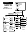
Contents
1
Overview
1-1
■ Managing
the System
and Capabilities
■ System Components
■ An Example System Setup
■ Specifications
1-1
1-2
1-3
1-6
1-8
Installing the Hardware
2-i
■ Important
Safety Instructions
Guidelines
■ Installing the Control Unit
■ Installing Telephones and Other Equipment
■ Removing and Replacing Modules
2-ii
2-1
2-2
2-4
2-6
System Programming
3-i
■ Overview
■ General
Instructions
■ Programming Procedures
3-1
3-4
3-5
Telephone Programming
4-i
■ Overview
a Receptionist Extension
■ General Programming Instructions
■ Programming Procedures
4-1
4-3
4-4
4-6
Using Telephones
5-i
■ System
5-1
5-7
5-10
5-11
■ Features
2
■ General
3
4
■ Programming
5
Telephones — Overview
Telephones — Overview
■ Combination Extensions
■ Using Your Telephone
■ Standard
i
6
Using Auxiliary Equipment
6-i
■ Fax
Machines
Machines
■ Modems
■ Credit Card Scanners
■ Night Service Operation
■ Call Reporting Devices (SMDR)
6-1
6-6
6-10
6-12
6-13
6-14
A
Dialing Restrictions Summary
A-1
B
User Forms.
B-1
C
Maintenance
C-1
D
Troubleshooting
D-1
IN
Index
IN-1
Programming Quick Reference
inside back cover
■ Answering
ii
1
Overview
Contents
Managing the System
Features and Capabilities
System Components
■ Contol
Unit
■ PARTNER Telephones
■ Auxiliary Equipment
An Example System Setup
Specifications
1-1
1-2
1-3
1-3
1-3
1-4
1-6
1-8
l-i
Managing the System
This guide explains everything you need to know about using your PARTNERTM
Plus Communications System. If you are responsible for managing the
system—whether you are a receptionist, an office manager, or the “resident
expert” on using it—you will find instructions and advice on the following topics:
Installing System Hardware. You may be able install the system hardware
and connect telephones yourself if your location already has modular jacks
for all outside lines and inside extensions. Chapter 2 helps you determine if
the existing wiring is usable and gives instructions for installing the system.
If the wiring is not usable or you prefer, a qualified technician can install the
system. Contact your AT&T Authorized Distributor for assistance.
The system supports a wide variety of auxiliary equipment, including fax
machines, modems, answering machines, credit card scanners, and SMDR
printers. See chapter 6 for advice on setting up such devices to work
effectively with the system.
Changing System Settings. You can change your system’s settings easily
to accommodate new or expanding needs. Chapter 3 gives instructions for
making whatever system changes are needed-from adding lines and
extensions to changing the features on a single extension. The chapter also
includes instructions for programming the entire system.
Programming Telephones. in addition to system programming, you can
program features on individual phones. You can complete this programming
either at the phone itself or from extension 10. Chapter 4 gives instructions
for programming telephones.
Training Co-Workers. Chapter 5 explains how to handle calls and use
system features effectively. To help with this task, give each telephone user
a Quick Reference card and filled-in copies of the “Speed Dial” and
“Extension Programming Information” forms in appendix B.
Solving Problems. Appendixes C and D provide information on maintaining
the system and solving problems. If your system or telephones malfunction,
you may be able to solve the problem by following the steps provided in
appendix D, “Troubleshooting.” If you still need help, contact your AT&T
Authorized Distributor.
Daily Operation. Depending on how your system is set up, you may need to
oversee some of the system’s daily operations, For example, if your system
is programmed to use the Night Service feature, you will need to turn on
Night Service at the end of each day before leaving the office. (See “Using
Night Service” in chapter 5.)
Overview
1-1
Features and Capabilities
The PARTNER Plus system is a digital telephone system that accommodates up
to eight telephone lines and up to 24 extensions. Although the system is sophisticated and powerful, it is easy to use and can readily change to meet your
company’s growing needs. The PARTNER Plus system includes all the features
and capabilities listed below:
Display-assisted programming makes it easy to reconfigure the system
yourself when you need to.
Direct connection of standard telecommunications devices means you
do not have to buy extra lines or expensive adapters to connect devices
such as standard touch-tone and rotary telephones, answering machines,
and fax machines to the PARTNER Plus system.
Fax Management feature lets users monitor fax machines from their telephones and transfer calls to them with a single touch.
Dialing restriction features allow you to control telephone activity and keep
phone bills down by restricting the kinds of calls your users can make,
including international calls and calls to certain districts.
Programmable telephone buttons give quick and convenient use of call
handling features such as Last Number Redial, Do Not Disturb, Auto Dialing,
and Privacy.
Quick Dialing allows users to call frequently used numbers by dialing a
short code or pressing a single button.
Group features allow users to call or page a group of phones simultaneously
and to automatically pickup calls ringing at a group of extensions.
Night Service prevents unauthorized use of telephones after normal business hours while allowing incoming calls to be answered.
Hotline feature lets you create a special hotline telephone that automatically
calls a predetermined extension when someone lifts the handset.
Doorphone feature lets you screen visitors through your phone without having to walk to and from a normally locked door.
Direct connection of a loudspeaker paging system and an audio source
for Music On Hold* means you do not have to buy special adapters or additional phone lines to connect loudspeakers or an audio source.
Interchangeable system components make the PARTNER Plus system
easy to install, maintain, and upgrade.
* If you use equipment that rebroadcasts music or other copyrighted materials, you maybe required to obtain a license
from a third party such as ASCAP or BMI. Or, you can purchase a Magic On Hold® system from AT&T that does not
require you to obtain such a license.
1-2
Overview
System Components
The PARTNER Plus system’s modular hardware design makes it easy to install
and expand. The main system component is the control unit, to which you connect telephones and other equipment.
Control Unit
The control unit includes:
Processor Module. The processor module contains the software that controls the system’s features. It also has 3 jacks for connecting a loudspeaker
paging system, SMDR, and an audio source for music on hold.
206 Modules. Phone lines, phones, and other equipment connect to the
modular jacks on 206 modules. Each module has jacks for 2 lines and 6
extensions. A system can have up to four 206 modules for a maximum of 8
lines and 24 extensions. The system requires at least one 206 module (purchased separately). A special 206 module containing hardware for periodic
pulse metering is also available.*
Backplane. All the modules slide easily into the backplane, which channels
power to the system.
Cover. The cover slides onto the front of the backplane.
PARTNER Telephones
AT&T manufactures four telephones specifically designed to work with your
PARTNER PlUS system:
Model MLS-34D, for up to 8 outside lines, has 34 buttons with dual lights, a
built-in speaker and microphone, and a display.
Model MLS-12D, for up to 8 outside lines, has 12 buttons with dual lights, 6
buttons without lights, a built-in speaker and microphone, and a display.
Model MLS-12 is the same as model MLS-12D without the display.
Model MLS-6, for up to 4 outside lines, has 6 buttons with dual lights and a
built-in speaker.
The system can have any combination of these phones, but extension 10 must
have a PARTNER display phone (MLS-34D or MLS-12D), for system programming.
* Periodic pulse metering is a means of determining call charges.
Overview
1-3
Auxiliary Equipment
The PARTNER Plus system also supports many telecommunications devices,
not only system telephones. You can connect almost any indusry-standard
device to your system and certain models of other devices, all without expensive
adapters or additional phone lines.
Industry-Standard
Devices
For best results, connect any
device with more than one line as
a single-line device.
Many types of industry-standard, single-line telecommunications devices will
work with your system:
Touch-tone and rotary telephones
Fax machines
Answering machines
Modems
Credit Card scanners
Cordless telephones
Limitations
You can connect almost any standard device to your system, regardless of the
manufacturer. However, note the following limitations for any such device:
It must be a single-line unit.
It must be industry standard and non-proprietary, That is, it cannot be made
specifically for use on a particular telephone system. (For example, you cannot connect an AT&T MERLIN® phone because it is specifically designed for
use on a MERLIN system.)
Its Ringer Equivalence Number (REN*) cannot be greater than 2.0. (The REN
is shown on a label, usually on the bottom of the device.)
Connecting and Using Standard Devices
You can connect a standard device so that it is on an extension by itself, or so
that it shares an extension with another piece of equipment (either another standard device or a system phone). For example, you can connect a standard
touch-tone phone and an answering machine to the same extension. (The total
RENs for both devices must not exceed 2.) To connect two devices on one
extension, you need an inexpensive AT&T 267F2 bridging adapter. Two
adapters are provided with each 206 module. See chapter 2 for installation
instructions.
For additional information on programming and using fax machines, answering
machines, modems, or credit card scanners, see chapter 6.
* REN is a measure of the power it takes to ring a phone. A typical home phone line can handle 4.0-5.0 RENs; each
extension jack in the PARTNER Plus system can handle 2.0 RENs.
1-4
Overview
Other Devices
You can connect non-standard devices to your system, but only specific models
are compatible with the system. Contact your AT&T Authorized Distributor for
details. These devices include:
Loudspeaker paging systems allow you to broadcast a message over a
large area, by connecting the paging system to the control unit processor
module. The system supports certain paging systems. Please check with
your AT&T Authorized Distributor. For information on how to use a
loudspeaker paging system with the system, see chapter 6.
Music-on-hold systems allow you to play recorded music to callers while
they are on hold, by connecting the music-on-hold system to the control unit
processor module, The system supports certain music-on-hold systems.
Please check with your AT&T Authorized Distributor.
Doorphones allow visitors to ring up to five extensions at once by pressing a
button on the doorphone; the person who answers a doorphone call can then
use the phone to speak to the visitor over the doorphone. The system supports up to two AT&T PARTNER Plus doorphones, which can be installed
indoors or outdoors. A doorphone is especially useful for providing access
to offices or departments after hours. For example, you can install a doorphone outside your building entrance to allow visitors to call selected extensions when the receptionist is not there and the front door is locked.
SMDR (Station Message Detailed Recording) tracks telephone usage on an
extension basis and prints this information in a standard report. SMDR
requires a suitable printer connected to the SMDR port on the PARTNER Plus
Turbo Processor. The SMDR feature provides detailed information on outgoing and incoming calls including date, time, duration, line number, extension
number, telephone number dialed, and pulse count. To collect the pulse
count, the feature requires 206 modules equipped with Periodic Pulse Metering hardware.
Headsets allow users to have private, hands-free conversations. A headset
is a combination earphone and microphone worn on the head, useful for
receptionists, salespeople or others who may need to have their hands free
while talking on the phone. AT&T sells several headsets.
Extra alerts are strobes, lights, chimes, horns, or bells that respond on
incoming calls. AT&T sells several extra alerts.
See chapter 2 for installation instructions.
Overview
1-5
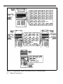
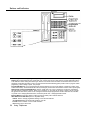
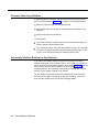
An Example System Setup
This PARTNER Plus System has 4 outside lines and 8 extensions connected to a variety of PARTNER phones and other equipment.
The boldface numbers refer to the following list, which gives a brief description of the system’s hardware components.
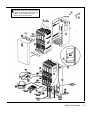
Control Unit. The heart of the PARTNER Plus system, the
control unit consists of a backplane, cover (not shown), one
processor module, plus up to four 206 modules. The
backplane channels power to the system and connects the
incoming telephone lines to the system.
Processor Module. The processor module contains the
electronics that provide most of the system features. It also
has audio, paging, and SMDR jacks.
Page Jack. The loudspeaker paging system plugs directly
to this modular jack.
Music-On-Hold Jack. The audio source plugs directly
into this RCA jack.
SMDR Jack. A call reporting device connects directly to
this jack.
206 Module. Each 206 module has jacks for 2 incoming
telephone lines and 6 extensions. The system can have up to
four 206 modules.
Line Jacks. Outside telephone lines connect to the top 2
jacks on each 206 module.
Extension Jacks. Telephones and other telecommunications equipment connect to the bottom 6 jacks on the 206
modules.
AC Power. An ordinary 220 VAC grounded wall outlet (not
controlled by an on/off switch) supplies power to the control
unit.
On/Off Switch.
Network Interface Jacks. Incoming telephone tines
service the system through these jacks. These lines can be
from the local telephone company or another system, such as
a PBX (Private Branch Exchange).
PARTNER Display Phone: Extension 10. The system
operator in this example is the receptionist on extension 10
and has a PARTNER MLS-12D phone. This phone can
handle 8 outside lines and has a display showing the time,
number dialed, duration of call, and programming messages.
Also, its programmable buttons (two with lights) can be
programmed to store additional features Auto Dial
numbers. Because the display is required for system
programming, extension 10 on your system must also have
an PARTNER display phone (MLS-12D or MLS-34D).
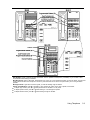
Standard Touch-Tone TeIephone Used as a Power
Failure Telephone. In a power failure, the first two
extension jacks on each 206 module connect to the outside
lines on that module to provide continuous service to standard non-PARTNER telephones. In this example system, the
PARTNER phone on extension 10 will not work during a
power failure. However, the receptionist can use the standard touch-tone phone connected to extension 10 to place
and receive calls on line 1.
AT&T 267F2 Bridging Adapter. This adapter combines
the standard touch-tone phone and the PARTNER display
phone on one extension jack. The adapter has two modular
jacks, one for each phone. You can use the bridging adapter
to combine any two devices (PARTNER telephones, industrystandard telephones, or other equipment) on one extension
jack as long as the totaI Ringer Equivalence Number on each
extension jack is 2 or less. The bridging adapter plugs into a
wall jack or directly into an extension jack on the 206 module.
Figure 1-1 Example System Setup
1-6
Overview
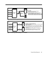
PARTNER MLS-12. This phone is like the PARTNER
MLS-12D phone, but it has no display.
PARTNER MLS-6 Phone and Answering Machine.
Using a 267F2 bridging adapter, both a MLS-6 phone and
an answering machine are connected to one extension. The
PARTNER MLS-6 phone accommodates up to 4 outside
lines.
lndustry-Standard Telephone. A standard single-line
touch-tone or rotary phone (such as you might have in your
home) is connected directly to the extension jack.
Doorphone. A doorphone is installed at the entrance.
When someone at the entrance presses the button on the
doorphone, up to 5 designated telephones in the office ring
automatically.
Bell. A Ioud bell connected directly to the extension jack
rings when the extension is called.
Fax Machine and Standard TeIephone. A fax
machine and standard touch-tone phone are connected
together on an extension jack.
Modem. A modem connected directly to an extension jack
provides data communications capability to the personal
computer.
Loudspeaker Paging System A paging system is
connected to the modular PAGE jack on the processor
module. The PARTNER Plus system is compatible with
AT&T’s paging systems.
Music-On-Hold Source. AT&T’s Magic on Hold®
cassette deck is connected to the RCA jack on the processor module to provide customized music and messages for
callers on hold. For information on Magic on Hold, call your
AT&T Authorized Distributor. You can connect any type of
audio equipment to your system (including a CD player,
casette player, stereo receiver, etc.), but you must supply an
audio cord with an RCA plug.
NOTE: Users of equipment that rebroadcasts copyrighted
music or other material maybe required to obtain a license
from a third party such as ASCAP or BMI.
1-7
Overview
Specifications
Table 1-1 Technical and Environmental Specifications
System
206 Module
Capacities
8 outside lines via line jacks on
four 206 modules
24 extensions via extension jacks
on four 206 modules
loudspeaker paging system via
PAGE jack on processor module
1 audio source via MUSIC ON
HOLD jack on processor module
1 SMDR device via SMDR jack on
processor module
2 doorphones, using 2 extension
jacks
Dimensions
Processor/206 modules
Control unit
MLS-34D telephone
Other PARTNER telephones
2 outside lines
6 extensions
Mansion Jack
Maximum 2 devices per extension
jack, total REN on jack not to
exceed 2 (2 devices require AT&T
267F2 bridging adapter). If a device lists 2 RENs, use the higher
number.
A PARTNER display phone
must be connected to
extension 10.
27.9cm(D) x 43.2cm(H) x 3.8cm(W)
(11" x 17" x 1.5")
30.5cm(D) x 48.3cm(H) x 27.9cm(W) (assembled)
(12" x 19" x 11")
24.6cm(D) x 13.5cm(H) x 25.4cm(W) (assembled)
(9.7" x 5.3" x 10")
24.1crn(D) x 12.7cm(H) x 17.1cm(W) (assembled)
(9.5" x 5" x 6.5")
Weights
(approx.)
Processor module
206 module
Backplane and cover
MLS-6 telephone
MLS-12 telephone
MLS-12D telephone
MLS-34D telephone
Switch Fabric
Full digital, nonblocking
Electrical
Specifications
2.2 amps peak current
200 watts at full system capacity
30-day memory backup (except clook and calendar)
Dissipation of power (65 watts during normal operation)
684 BTUs/hour at peak 225 BTUs/hr at normal
Extension Jack
Specifications
Ringing Voltage: +5 VDC, -200 VDC peak to peak trapezoidal wave shaping
Talk battery: 35 to 38 volts
Ringing frequency: 25 Hz
Environmental
Requirements—
Control Unit
Mount on a wall or sturdy, level surface at least 0.6 meters (2 feet) from the floor (wall mounting strongly recommended)
Locate within 1.5 meters (5 feet) of an electrical outlet not controlled by a switch and within
1.5 meters (5 feet) of the network interface jacks, when using supplied 2.1-meter (7-foot)
cords.
Operating temperature 0° to +40°C (32° to 104°F), not in direct sunlight
Humidity 15%-90%, noncondensing
Ventilation (2.4cm (6") space minimum on top, front, and right sides to avoid heat)
Locate in an area free of excess moisture, corrosive gases, dust, and chemicals
1-8
Overview
1.8 kgs (4.0 Ibs)
2.0 kgs (4.5 lbs)
2.5 kgs (5.5 Ibs)
0.8 kgs (1 .8 Ibs)
0.9 kgs (2.0 Ibs)
1.0 kgs (2.1 lbs)
1.2 kgs (2.6 Ibs)
Table 1-1 Technical and Enviromental Specifications (cont)
Electrical
Requirements
180-264 VAC, 50-60 Hz, 3-prong outlet separate ground, separately fused at 10 amps
Outlet must not be controlled by an on/off switch
Grounding
A. An insulated grounding conductor that is not smaller in size and equivalent in insulation
material and thickness to the grounded and ungrounded branch circuit supply conductors, except that it is green with or without one or more yellow stripes, is to be installed
as part of the circuit that supplies the product or system.
B. The grounding conductor mentioned in item A is to be connected to ground at the service equipment.
C. The attachment-plug receptacles in the vicinity of the product or system are all to be of
a grounding type, and the grounding conductors serving these receptacles are to be
connected to earth ground at the service equipment.
Wiring
MLS telephones: both AT&T PDS and at least 2-pair (4-wire) star (“home run” not “loop”)
Other standard telecommunications equipment (single-line phones, fax machines, answering
machines, etc.): 1-pair (2-wire) mounting cords (AT&T D2R or equivalent mounting cords
recommended)
Bridging adapter: AT&T 267F2
Local Phone
Company
Information
REN: 0.9A for each outside line jack
Jack type: RJ11C or equivalent
Loop start lines
Overview
1-9
Installing the Hardware
2
Contents
Important Safety Instructions
General Guidelines
Installing the Control Unit
Installing Telephones and Other Equipment
Removing and Replacing Modules
■ Removing
a Module
■ Removing a Module
2-ii
2-1
2-2
2-4
2-6
2-6
2-6
2-i
Important Safety Instuctions
Always follow these basic safety precautions when using the system:
1.
Read and understand all instructions.
2.
Follow all warnings and instructions marked on the product.
3.
DO NOT block or cover the ventilation slots and openings. They
prevent the product from overheating. DO NOT place the product in a
separate enclosure, unless proper ventilation is provided.
4.
Never spill liquid on the product or drop objects into the ventilation
slots and openings. Doing so may result in serious damage to the
components.
5.
Repair or service must be performed by a qualified repair person.
6. The product is provided with a 3-wire grounding type plug. This is a
safety feature. DO NOT defeat the safety purpose of the grounding
type plug. DO NOT staple or otherwise attach the AC power supply
cord to building surfaces.
7.
DO NOT use the product near water or in a wet or damp place (such as
a wet basement).
Additional Safety Instructions for Installation Personnel
Install the product to meet all environmental and electrical requirements
listed in the specifications (see pages 1-8 and 1-9).
1.
DO NOT install telephone wiring during a lightning storm.
2.
DO NOT install telephone jacks in a wet location unless the jack is
specifically designed for wet locations.
3.
Never touch uninsulated telephone wires or terminals, unless the
telephone line has been disconnected at the network interface.
4.
Use caution when installing or modifying telephone lines.
5. The system control unit must be securely wall mounted.
CAUTION:
Do not install PARTNER telephones out of the building.
CAUTION
Use only AT&T-manufactured PARTNER modules in the PARTNER Plus
Communications System.
SAVE THESE INSTRUCTIONS
2-ii
Installing the Hardware
General Guidelines
Instructions for installing the control unit, telephones, and other equipment are
on the following pages (figures 2-1 to 2-4). Before you begin, please note the
following guidelines:
Install the control unit so that it meets the environmental and electrical
requirements listed in Table 1-1 (pages 1-8 and 1-9).
If wall mounting the control unit, you will need four#12 screws appropriate
for the type of wall and weight of the control unit.
When connecting wires to the jacks on a 206 module, leave at least 60 cm
(2 ft.) of slack for removing the module without first disconnecting the wires.
If you later replace the module, you can remove the old module with the
wires in place and plug them into the new module one at a time.
PARTNER phones require at least 2-pair wiring and are compatible with
AT&T 4-pair PDS wiring or equivalent.
Standard phones and other equipment require l-pair mounting cords (AT&T
D2R or equivalent mounting cords recommended).
When connecting two devices to a single extension, use only an AT&T 267F2
bridging adapter.
Connect a PARTNER display phone to extension 10 for system programming.
Do not connect doorphones to extensions 10, 11, 16, 17, 22, 23, 28, or 29.
Do not install PARTNER phones out of the building.
A hotline phone must be a standard, single-line phone, not a PARTNER telephone. However, the hotline phone can ring any type of phone.
During a power outage, neither the system’s features nor PARTNER phones
work. However, standard, single-line touch-tone or rotary phones connected
to extensions 10, 11, 16, 17, 22, 23, 28 and/or 29 can be used to place and
receive calls. These extensions connect directly to the outside lines in the
system. To prepare for a power failure, AT&T recommends:
If you combine a standard phone
and PARTNER phone on one
extension, you may want to turn
off the ringer of the standard
phone during normal use.
Store standard phones close to extensions 10, 11, 16, 17, 22, 23, 28
and/or 29. During a power failure, replace the PARTNER phone with the
standard phone. Or, connect a standard phone to these extensions at all
times, either by itself or combined with an PARTNER phone via a 267F2
bridging adapter.
Do not program a Hotline on these extensions to keep them available for
power failure use.
If upgrading from a one-module PARTNER system, remove the rubber feet
that may be attached to the 206 module before installing.
If upgrading from a two-module PARTNER system, remove the module connector from the the two modules.
Installing the Hardware
2-1
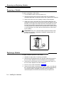
Installing the Control Unit
CAUTION: To prevent electrostatic discharge, overheating or
other damage, environmental and electrical conditions must meet
the specifications on pages 1-8 and 1-9.
MOUNT THE BACKPLANE ON A WALL
Press the On/Off switch to the "on" position.
Check all green lights on the front of the unit. lf any lights are out
turn off the system and reseat the module.
To test the lines, plug a PARTNER MLS-34D or MLS-12D phone
into extension 10. Press the line button for each outside line and
listen for dial tone. Repeat for extensions 11, 16, 17, 22, 23, 28
and 29.
Turn off and disconnect the power cord from the wall outlet before
continuing.
Hold the backplane in place on the wall. Using the four screw
keyholes in the backplane as a template, mark the screw locations
on the wall.
Start the four #12 screws, leaving them about 6.3cm (1/4") out
from the wall. Use screws appropriate for the wall surface —
CONNECT THE MODULAR TELEPHONE CORDS
when loaded with five modules, the control unit weighs 17kg
Connect the modular telephone cords from the telephones to the
(37.5) pounds.
extension jack on the 206 modules, starting with the top extenSlip the Backplane onto the screws and tighten them.
sion jack on the leftmost 206 moduIe. Route the cords though the
hook on the front of the module, then though the slot between the
INSERT THE MODULES
module and the base of the backplane. Leave at least 60 cm
(2 feet) of slack in the cords so that you can easily reconnect the
CAUTION: Do not connect AC power cord before inserting
cords during replacement.
modules.
SOURCE (OPTIONAL)
Slide the first 206 modules straight into the leftmost slot of the CONNECT THE MUSIC-ON-HOLD
backplane. Push slowly but firmly until the module snaps into
Follow these steps to connect audio source to the control unit. (Assemble)
place (you should hear and feel two snaps). The module must be and use according to the manufacturer's directions.)
securely attached to the rear of the backplane and held into place
Using a flathead screwdriver, turn the volume control on the
by the locking tab on the bottom front of the backplane/module
processor couterclockwise to the lowest setting.
slot. lnsert the next 206 module in the second slot from the left.
lnsert the RCA plug into the RCA jack on the processor (labeled
Note the alignment of dovetails between each module when
MUSIC ON HOLD). Route the cord through the hook on the front
modules are installed next to each other.
of the module and the slot between the module and the base of
the backplane.
CAUTION: Do not force the module. If it does not insert easily,
put down on the front locking tab, remove the module, clear any
Connect the cord to the music-on-hold source according to the
obstruction, and insert the module again.
manufacturer's directions. Use programming procedure #602 to
enable music on hold, then adjust the volume using the volume
Insert the processor module in the center slot. lnsert the other 206
control on the processor. Place a call on hold and listen to the
modules from left to right, without skipping slots.
Ievel while adjusting.
Label the line and extension jacks as shown below:
CONNECT THE LOUDSPEAKER PAGING SYSTEM
(OPTIONAL)
LINES
Only the steps for connection to the control unit are included here. Follow the
manufacturer's directions for setting up and using it.
Insert the modular plug for the paging system into the modular
jack labeled PAGE on the processor. Route the cord as described
in step 15.
EXTENSIONS
Connect the cord to the loudspeaker paging system according to
the manufacturer's directions.
CONNECT THE STATION MESSAGE DETAIL RECORDING
(SMDR) DEVICE (OPTIONAL)
Only the steps for connection to the control unit are included here. Follow the
CONNECT THE OUTSIDE TELEPHONE LINE CORDS
manufacturer's directions for setting up and using it.
Test for dial tone at the network interface jacks before connecting outside lines.
Insert the modular plug for the SMDR device into the modular jack
labeled SMDR on the processor. Route the cord as described in
Connect the outside telephone line cords to the line jacks on the
step 15.
206 rnodules, starting with the top line jack on the leftmost 206
module. Route the cords along the telephone cords. Leave
Connect the cord to the SMDR device according to the
at least 60 cm (2 feet) of slack in the cords so that you can easily
manufacturer's directions.
reconnect the cords during replacement.
CONNECT THE AC POWER CORD
Connect the free end of each line cord to th appropriate network
Connect the power cord as described in steps 9 and 10.
interface jacks.
ON/OFF SWITCH
Connect the AC power cord to the power jack on the top right rear Press AC power switch to "power-up" the system.
of the backplane. Press firmly until it locks into place.
INSTALL THE OUTSIDE COVER
Plug the other end of the power cord into a grounded 3-prong wall
Holding the cover, slide the cover onto the front of the
oulet not controlled by a switoh.
modules until it meets the backplane.
TEST THE SYSTEM
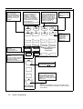
Figure 2-1 Control Unit Installtion
2-2
Installing the Hardware
WARNlNG: There are no field-serviceable
components inside 206 modules, processor
modules or the backplane. Hazardous
voltages within. DO NOT OPEN!
Installing the Hardware
2-3
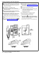
Istalling Telephones and Other Equipment
CAUTION: PARTNER phones must be connected with a
2-pair telephone wire. Other equipment must be connected
with a 1-pair mounting cord (AT&T D2R mounting cords or
equivalent recommended).
DESK MOUNTING A PARTNER PHONE
Plug one end of the handset cord into the jack on the
handset. Plug the other end of the cord into the small jack on
the left side of the base.
Plug one end of the telephone mounting cord into the big
jack on the base of the phone. Push the cord in place along
the channel on the base of the telephone.
If the telephone has an adjustable stand, snap it onto the
base of the telephone. The stand can be installed in one of
two positions (high or low) to change the angle of the
telephone. Refer to the instructions included with the stand.
Plug the other end of the mounting cord into the modular wall
jack.
Test the intercom. Lift the handset, then press an [ Intercom ]
button. You should hear an intercom dial tone. If not, see
appendix D (“Phone Has Lights but No Dial Tone”).
Figure 2-2 Desk Mounting a PARTNER Telephone
2-4
Installing the Hardware
Test the outside line connection. Lift the handset and press an
outside line button. You should hear an outside dial tone. If
not, see appendix D (“Phone Has Lights but No Dial Tone”).
Slide the Quick Reference card under the telephone.
Label the button sheet and insert as follows:
1 Remove the clear plastic cover from the phone—gently
press down on the center tab, then lift.
2 Place a button label sheet on the phone so the holes on
the sheet fit over the buttons.
3 Replace the plastic cover.
TEST PROCEDURE FOR PARTNER PHONES
To test the power and lights on a PARTNER phone:
1 Press and hold the [ # ] button for 5 seconds.
2 Before releasing the [ # ] button, lift the handset. All lights
should light, the ringer should sound, and on the PARTNER
display phone, a test pattern should appear on the display.
If not, call your service representative.
3 Replace handset. The phone is in normal operating mode.
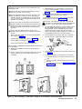
WALL MOUNTING A PARTNER TELEPHONE
Reverse the plastic hook that sits in the earpiece part of the
handset cradle.
Remove the screws in the base of the telephone. Turn the
base 180° and screw it back into place.
3 Test a telephone by lifting the handset. You should hear a
dial tone, indicating a good connection on the Iine. If you
don’t, see appendix D (“Phone Has Lights but No Dial
Tone”).
Plug the telephone mounting cord into the large jack on the
base of the telephone. Push the cord into place along the
channel on the base of the telephone. If you need a shorter
cord, use AT&T’s 61 cm (2-foot) D4BU-29 mounting cord or
equivalent (not provided).
If you install a fax machine and want to assign a Fax Management button,
see page 3-33 to program the extension as a fax extension.
Plug the other end of the mounting cord into the wall jack.
INSTALLING TWO DEVICES ON ONE EXTENSION
CAUTION: To avoid malfunction, follow these Installation
instructions, not the ones provided with the equipment.
Mount the telephone on the wall phone jack using the screw
keyholes on the base of the telephone. For proper mounting,
the wall jack must bean AT&T 630B connecting block or
equivalent.
If you install a doorphone, program the system to recognize the Doorphone
and Doorphone Alert extensions. See pages 3-36 — 3-38.
Plug one end of the handset cord into the jack on the
handset. Plug the other end into the small jack on the side of
the base.
1 After assembling the equipment, plug the mounting cord of
the non-PARTNER device into the top jack of the 267F2
brigding adapter. Plug the PARTNER phone or second
standard device into the bottom jack (the one with four
wires). If the standard device’s mounting cord is loose, use
an AT&T D2R mounting cord or equivalent instead.
Test the inside and outside line connections as described in
steps 5 and 6 of figure 2-2.
2 Plug the adapter into the modular wall jack or directly into
the extension jack of a 206 module. Below is an example:
Label the phone as described in step 8 of figure 2-2.
Test the telephone as described in figure 2-2.
Place the Quick Reference card near the telephone.
INSTALLING STANDARD TELEPHONES AND OTHER
EQUIPMENT
1 Assemble the equipment according to the manufacturer’s
instructions.
2 Plug the mounting cord into the modular wall jack. If the plug
is loose in the jack, use an AT&T D2R mounting cord or
equivalent.
3 Test the inside and outside lines as described in steps 5 and
6 of figure 2-2.
4 If installing two phones on one extension, test connection:
1 Pickup the handset of the first phone and listen for dial
tone.
2 Pickup the handset of the second phone and listen for
dial tone.
3 If no dial tone, see appendix D ("Phone Has Lights but
No Dial Tone").
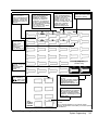
Figure 2-3 Wall Mounting a PARTNER Telephone and Installing Other Equipment
Installing the Hardware
2-5
Removing and Replacing Modules
Removing a Module
To remove a processor or 206 module:
1. Turn the ON/OFF switch to the OFF position (“O”).
2. Disconnect the AC power cord from the wall outlet. Do not attempt to
disconnect the power cord from the control unit; a special tool is required.
3. Remove the control unit cover by sliding it directly off the backplane.
4. Grasp the front top of the module with one hand while holding down the
locking tab at the base of the module with the other hand. With the locking
tab down, put one finger of the same hand in the wire bracket on the bottom front of the module. Using both hands, pull the module forward and
out, being careful not to strain the wires connected to the module, (If there
is not enough slack in the wires, label and disconnect them before removing the module.)
WARNING There are no field-serviceable components inside the 206
modules, the processor, or backplane. Hazardous voltages within. DO
NOT OPEN THE MODULES!
Replacing a Module
To replace a defective processor or 206 module:
1. Complete the steps above for removing the module.
2. Disconnect the first telephone line from the old module and connect it to
the new module. Repeat for the second telephone line (if applicable).
3. Disconnect the first extension line from the old module and connect it to
the new module. Repeat for the other extensions.
4. Insert the new module as described in figure 2-1.
5. Connect the AC power cord and press the ON/OFF switch to the ON position. The system performs the necessary reset procedures automatically.
You should not need to reprogram the system unless you added or
removed telephone lines and/or extensions during the replacement.
2-6
Installing the Hardware
System Programming
Contents
Overview
■ Programming
Methods
Programming Extension
■ The Programming Overlay
■ The
General Programming Instructions
Programming Procedures
■ #101
System Date
■ #102 System Day
■ #103 System Time
■ #104 Number of Lines
■ #105 Transfer Return Rings
■ #106 PBX Dial-Out Code
■ #107 Recall Timer Duration
■ #108 Rotary Dialing Timeout
■ #110 System Programming Password
■ #201 Dial Mode
■ #202 Line Type
■ #301 Line Assignment
■ #302 Line Use Restriction
■ #303 Display Language
■ #304 Automatic Privacy
■ #305 Abbreviated Ringing
■ #306 Joining a Call
■ #307 Call Waiting
■ #399 Copy Settings
■ #401 Outgoing Call Restrictions
■ #403 System Password
■ #404 Disallowed Phone Number Lists
■ #405 Disallowed List Assignment
■ #406 Emergency Phone Number List
■ #407 Allowed Phone Number Lists
■ #408 Allowed List Assignment
■ #501 Pickup Group Extensions
3-1
3-1
3-1
3-1
3-4
3-5
3-5
3-5
3-6
3-7
3-8
3-9
3-10
3-11
3-11
3-12
3-13
3-14
3-15
3-16
3-17
3-18
3-19
3-20
3-21
3-22
3-23
3-24
3-25
3-26
3-27
3-28
3-29
3-i
■ #502
Calling Group Extensions
Night Service Button
■ #504 Night Service Group
■ #601 Fax Machine Extensions
■ #602 Music On Hold
■ #603 Hotline
■ #604 Doorphone 1 Extension
■ #605 Doorphone 2 Extension
■ #606 Doorphone Alert Extensions
■ #607 SMDR Output
■ #728 System Reset-Programming Saved
■ System Speed Dial Numbers
■ #503
3-ii
3-30
3-31
3-32
3-33
3-34
3-35
3-38
3-37
3-38
3-39
3-40
3-40
Overview
This chapter provides instructions for programming your system. Your
PARTNER PIUS system was programmed at the factory so that it works when
installed. However, the needs of your business may require that you change
some or all of the factory settings. System programming allows you to change
these factory settings.
For example, after a power failure, you will need to reset the system time to be
accurate. This change is easy to make through system programming. System
programming also lets you customize the system to work best for your business.
For example, you may not want all extensions to have all outside lines. Using
system programming, you can assign lines on an extension-by-extension basis.
Programming Methods
The PARTNER Plus system has more than 30 system programming procedures,
each identified by a 3-digit code. Using these codes, you can program the
system in one of two ways:
Direct Method. With this method, you enter the procedure’s 3-digit code
followed by data. This method is best for completing one or two procedures
at a sitting.
Cycle Method. With this method, you cycle through the procedures in
numerical order. This method is best for programming the system thefirst
time or for changing several settings. You can skip procedures without
changing their settings.
Detailed instructions for programming are included in the rest of this chapter,
beginning on page 3-4. Once you are familiar with the basic programming
steps, the Programming Quick Reference on the inside back cover of this guide
is especially useful. This chart lists all the procedures and possible settings.
The Programming Extension
System programming must be performed at extension 10 on a PARTNER
display phone (MLS-12D or MLS-34D). As you program, messages on the
display prompt you to enter data. You can program the system with the handset
on or off the phone; you may even be on a call. This capability is useful for
working with technical support personnel on troubleshooting. However, you
cannot be on the speaker or microphone during programming.
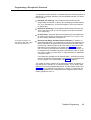
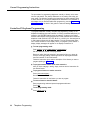
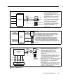
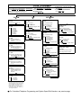
The Programming Overlay
The normal functions of several buttons on the display phone at extension 10
change during system programming. For example, the left [ Intercom ] button
becomes [ System Program ] , the button used to enter program mode. To identify
these buttons while programming, place the appropriate programming overlay
provided with the system on the dial pad of extension 10. Figures 3-1 and 3-2
show the programming overlays for the MLS-12D and MLS-34D phones, with
descriptions of the special buttons.
System Programming
3-1
Next Prodcedur/
Prev Procedure
Cycles forward/backward
through the programming
procedures. You can use
these buttons to select a
procedure.
Next Data/Prev Data
Cycles forward/backward
through the valid data entries.
These buttons work only for
fixed data, such as a line or
extension number. They do
not work for variable data such
as date, time, password,
telephone numbers, or
doorphone assignments.
Next ltem/Prev Item
Cycles forward/backword
through a procedure’s
parameters. A parameter
is usually an outside line,
an extension, or a telephone
list entry. If a procedure has
two parameters (for example,
a lined extension),
Next Item/Prev Item affects
only the second one.
Remove
Returns the current
setting to the factory
setting.
Enter
Ends an entry of
variable length, such
as a telephone
number in an
Allowed Phone
Number List.
System Program
(Intercom)
Starts the system
programming process.
PARTNER Plus communications System
Programming Overlay
(use at Ext 10 only)
Central Tel Program
(Intercom)
Starts the centralized telephone
programming process (that is,
custimizing individual
telephones from extension 10).
Feature
When followed by [ 0 ][ 0 ] , enters
or exits programming mode.
Wild
Enters a "wildcard" (a character
that matches any digit dialed
in telephone numbers in Allowed,
Disallowed, and emergency Phone
Number Lists.
AT&T 518-455-220
Comcode 846546687
NOTE:
This is a full-size illustration. If you lose the original, you can
photocopy this illustration and carefully cut out the openings
for the bottons.
Figure 3-1 Programming Overlay for MLS-12D Phone
3-2
System Programming
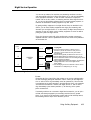
Next Procedure/
Prev Procedure
Cycles forward/backward
through the programming
procedures. You can use
these buttons to select a
procedure.
Next Item/Prev Item
Cycles forward/backward
through a procedure’s
parameters. A parameter
is typically an outside line,
an extension, or a telephone
list entry. If a procedure has
two parameters (for example,
a line and extension),
Next Item/Prev Item affects
only the second one.
Next Data/Prev Data
Cycles forward/backward
through the valid data entries.
This button works o for
fixed data, such as a line or
extension number. They do
not work for variable data such
as date, time, password,
telephone numbers, or
doorphone assignments.
Remove
Returns the current setting
to the factory setting.
Enter
Ends an entry of
variable length,
such as a
telephone number
in an Allowed
Phone Number List.
PARTNER Plus Communication System
Programming Overlay
(use at Ext. 10 only)
System Program
(Intercom)
starts the system
programming
process.
System
Program
Feature
When followed by
[ 0 ][ 0 ] , enters or exits
programming mode.
Central
Tel Program
Central Tel Program
(Intercom)
Starts the centralized telephone
programming process (that is,
customizing individual
telephones from extension 10).
Wild
Enters a "wildcard" (a character
that matches any digit dialed)
in telephone numbers in Allowed,
Disallowed, and Emergency Phone
Number Lists.
AT&T
518-455-221
Comcode
846704088
Figure 3-2 Programming Overlay for MLS-34D Phone
NOTE:
This is a full-size illustration. If you lose the original,
photocopy the illustration and carefully cut out the openings
for the buttons.
System Programming
3-3
General Programing Instructions
Programming the PARTNER Plus system requires no complicated steps or
intensive training. By following the detailed instructions given in therest of this
chapter, you can quickly change system settings. As you become familiar with
programming, use the Programming Quick Reference on the inside back cover
of this guide for procedure codes and settings.
The detailed instructions for each procedure include:
A brief description of the procedure
Valid data entries or procedure settings
Considerations for how the procedure interacts with other procedures (if
appropriate)
Remember to place the programming overlay on the dial pad of
extension 10 before starting.
Programming notes and steps including:
Entering system program mode, including password when required
Selecting the procedure
Selecting items-fines, extensions, list, and phone numbers—if necessary
Entering data
The instructions use the initial factory setting (designated with an ✓ in the valid
entries section). If your system has been previously programmed, the displays
may differ.
Once you’ve completed the steps in the detailed instructions, the data setting is
saved. You can now
When you go to another procedure, start with step 2 of the
instructions for the new procedure.
go to another procedure,
return the data to the factory setting, or
exit program mode.
Instructions for these choices are given in the box shown on the bottom of every
two pages:
You can also exit program mode
by lifting and replacing the
handset, or by replacing it if it
has bean lifted.
✔ = Factory Setting
To go to a specific procedure: [ # ] [ x ] [ x ] [ x ]
To go to the next procedure: [ Next Proc ]
To go to the previous procedure: [ Prev Proc ] (where X X X is the Procedure number)
To return data to the factory setting: [ Remove ] To exit system programming: [ Feature ] [ 0 ] [ 0 ]
IMPORTANT: To change most of the programming procedures, you must
enter a 4-digit system programming password. This password is shown by
[ x ] [ x ] [ x ] [ x ] in the programming instructions. You may change the system
programming password through programming procedure #110 or use the factory set password, 7 7 7 7 . You do not need to enter the password for changing
the System Date (#101 ), System Day (#102), System Time (#103), and System
Password (#403). For more information on the System Programming Password,
see page 3-11.
3-4
System Programming
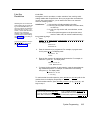
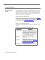
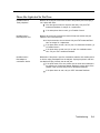
Programming Procedures
System Date
Code: #101
If your system has been previously programmed, the displays
may differ.
Description: The day, month, and year that appears on PARTNER display
phones
Valid Entries: Any date
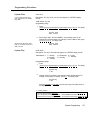
Programming Step:
1. Press:
[ Feature ] [ 0 ] [ 0 ] [ System Program ] [ System Program ] [ # ] [ 1 ] [ 0 ] [ 1 ] .
reads.
The display
System Date
Data 010100
2. Enter today’s date in the form DDMMYY, using leading zeroes for all
single-digit months and dates. For example, to enter 4 March 1992, press
[ 0 ] [ 4 ] [ 0 ] [ 3 ] [ 9 ] [ 2 ] . The display reads:
See the box at the bottom of this
page for a summary of options of
what to do next.
System Day
System Date
Data 040392
Code: #102
Description: The day of the week that appears on PARTNER display phones
4 = Wednesday 6 = Friday
Valid Entries: ✔ 1 = Sunday
7 = Saturday
5 = Thursday
2 = Monday
3 = Tuesday
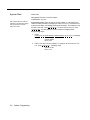
Programming Steps:
1. Press:
[ Feature ] [ 0 ] [ 0 ] [ System Program ] [ System Program ] [ # ] [ 1 ] [ 0 ] [ 2 ] .
The display
reads:
System Day
1 Sun
2. Change the day by entering a new setting number as listed above. For
example, to set the day to Tuesday, press [ 3 ] . The display reads:
System Day
3 Tue
Or press [ Next Data ] or [ Prev Data ] until the correct day of the week shows on
the display.
✔ = Factory Setting
To go to a specific procedure: [ # ] [ x ] [ x ] [ x ]
To go to the next procedure: [ Next Proc ]
To go to the previous procedure: [ Prev Proc ] (where X X X is the procedure number)
To return data to the factory setting: [ Remove ] To exit system programming: [ Feature ] [ 0 ] [ 0 ]
System Programming
3-5
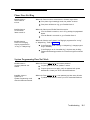
System Time
Code: #103
Description: The time, in 24-hour notation
Valid Entries: Any time
After a power failure you will see
asterisks in the telephone display
and you will have to reset the
time to be correct.
Programming Notes: Enter the time in 24-hour notation. In this scheme, the
hours of the day are 0000 (12 midnight) to 2359 (11:59 p.m.). Since each time
must have four digits, use leading zeroes when necessary. For example, to set
the time to 9:00 a.m., enter [ 0 ] [ 9 ] [ 0 ] [ 0 ] . To set the time to 4:45 p.m., enter
[ 1 ] [ 6 ] [ 4 ] [ 5 ] . The time appears in 24-hour notation on display phones.
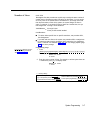
Programming Steps:
1. Press:
[ Feature ] [ 0 ] [ 0 ] [ System Program ] [ System Program ] [ # ] [ 1 ] [ 0 ] [ 3 ] .
The display
reads:
System Times
Data 0000
2 . Enter a new time in 24-hour notation. For example, to set the time to 2:15
p.m., press [ 1 ] [ 4 ] [ 1 ] [ 5 ] . The display reads:
System Time
Data 1415
3-6
System Programming
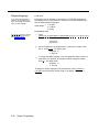
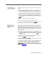
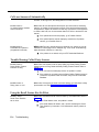
Number of Lines
Code: #104
Description: Use this procedure as a quick way to assign the same number of
outside lines to all extensions when first setting up the system. You can assign
all or only some of the outside lines to all extensions. If you assign fewer lines
than the total number of lines in the system, the system assigns the lines in
order. For example, if you assign 5 lines but there are 8 outside lines, the system assigns lines 1 through 5 to all extensions.
Valid Entries:
0 through 8 lines
✔ 2 lines per 206 module installed
Considerations:
To add or delete specific lines on specific extensions, use procedure #301,
Line Assignment.
If you later add more lines to the system, use procedure #301 to assign them
to extensions rather than this procedure, which returns the Line Assignment
(#301), Automatic Line Selection (page 4-6), and Line Ringing Options (page
4-7) to the factory settings.
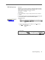
Programming Steps
[ x ] [ x ] [ x ] [ x ] Stands for the Sys-
tem Programming Password.
See procecure #110.
1. Press:
[ Feature ] [ 0 ] [ 0 ] [ System Program ] [ System Program ] [ x ] [ x ] [ x ] [ x ] [ # ] [ 1 ] [ 0 ] [ 4 ] .
The display reads:
Number Of Lines
8 Lines
2. Enter the correct number of lines. For example, to tell the system there are
7 outside lines, press [ 7 ] . The display reads:
Number Of Lines
7 Lines
✔ = Factory Setting
To go to the next procedure: [ Next Proc ]
To go to the previous procedure: [ Prev Proc ]
To return data to the factory setting: [ Remove
To go to a specific procedure: [ # ] [ x ] [ x ] [ x ]
(where X X X is the procedure number)
] To exit system programming: [ Feature ] [ 0 ] [ 0 ]
System Programming
3-7
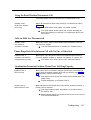
Transfer Return
Rings
Code: #105
Description: Defines the number of times an extension should ring with a
transferred call before the call returns to the originating extension.
Valid Entries:
0 (transferred calls not returned to originating extension)
1 through 9
✔4
Considerations: If you have a fax machine or an answering machine connected
to the system, set this number greater than the number of rings at which these
devices answer. Doing so prevents a call transferred to a fax or answering
machine from returning before it is answered.
Progamming Steps:
[ x ] [ x ] [ x ] [ x ] stand for the Sys-
tem Programming Password.
See procedure #110.
1 . Press:
[ Feature ] [ 0 ] [ 0 ] [ System Program ] [ System Program ] [ x ] [ x ] [ x ] [ x ] [ # ] [ 1 ] [ 0 ] [ 5 ] .
The display reads:
Transfer Return
4 Rings
2. Enter a different setting. For example, to set a transfer return of 5 rings,
press [ 5 ] . The display reads:
Transfer Return
5 Rings
3-8
System Programming
.
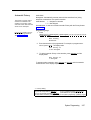
PBX Dial-Out Code
Code: #106
Description: If your system is connected to a PBX (Private Branch Exchange)
instead of directly to the local phone company’s switching system, use this procedure to identify the digit you dial to get an outside line.
Valid Entries:
0 through 9
✔0
Considerations:
Use procedure #202, Line Type, to identify the lines that are connected to
the PBX.
Do not include the dial-out code in System Speed Dial, Personal Speed Dial,
and Auto Dial numbers. The system automatically supplies it.
Programmi ng Steps:
[ x ] [ x ] [ x ] [ x ] stands for the Sys-
tem Programming Password.
See procedure #110.
1. Press:
[ Feature ] [ 0 ] [ 0 ] [ System Program ] [ System Program ] [ x ] [ x ] [ x ] [ x ] [ # ] [ 1 ] [ 0 ] [ 6 ] .
The display reads:
PBX DialOut Code
Data 0
2 . Enter the correct dial-out code. For example, if you dial [ 8 ] to dial out,
press [ 8 ] . The display reads:
PBX DialOut Code
Data 8
✔ = Factory Setting
To go to a specific procedure: [ # ] [ x ] [ x ] [ x ]
To go to the next procedure: [ Next Proc ]
To go to the previous procedure: [ Prev Proc ] (where X X X is the procedure number)
To return data to the factory setting: [ Remove ] To exit system programming: [ Feature ] [ 0 ] [ 0 ]
System Programming
3-9
Recall Timer
Duration
Code: #107
Description: Changes the length of the timed signal (a switchhook flash) executed by the Recall feature (page 4-10) and by the Recall function of speed dialing (page 3-42). Recall sends this timed signal over the phone line to the local
telephone company or PBX to which the system is connected. Typicallyyou use
the Recall feature to access PBX features such as Call Waiting.
Change the factory setting of the recall timer only under two conditions:
If your PARTNER Plus system is connected to a PBX and Recall drops calls,
shorten the time.
If pressing Recall has no effect, lengthen the time.
Valid Entries:
01 through 80 (25 to 2000 msec in 25 msec increments)
✔ 32 (800 msec)
Programming Steps:
[ x ] [ x ] [ x ] [ x ] stands for the Systern Programming Password.
See procodure #110.
1 . Press:
[ Feature ] [ 0 ] [ 0 ] [ System Program ] [ System Program ] [ x ] [ x ] [ x ] [ x ] [ # ] [ 1 ] [ 0 ] [ 7 ]
.
The display reads
Recall Timer
32 800-msec
2 . Enter a different recall timer setting by pressing [ Next Data ] or [ Prev Data ] . For
example, to shorten the recall timer to 750 msec, press [ Prev Data ] twice.
The display reads:
Recall Timer
30 750-msec
Or enter the setting number directly. For example, to set the recall timer to
750 msec, press [ 3 ] [ 0 ] .
3 . If you are using Recall to access PBX features, test the new Recall Timer
Duration by trying to use these features:
If the call is disconnected, shorten the time.
If the Recall signal has no effect, lengthen the time.
✔ = Factory Setting
To go to the next procedure: [ Next Proc ]
To go to a specific procedure: [ # ] [ x ] [ x ] [ x ]
To go to the previous procedure: [ Prev Proc ] (where X X X is the procedure number)
To return data to the factory setting: [ Remove ] To exit system programming: [ Feature ] [ 0 ] [ 0 ]
3-10
System Programming
Rotary Dialing
Timeout
Code: #108
Description: If you have any rotary lines and are having trouble calling out on
standard touch-tone phones, use this procedure to change the length of the
Rotary Dialing Timeout, For example, if users dial slowly and calls are not completed or are connected to wrong numbers, lengthen the timeout. Do not
change this setting unless the system is experiencing problems.
Valid Entries:
1 = 4 seconds
✔ 2 = 8 seconds
3 = 12 seconds
Considerations: Use this procedure only if the Dial Mode (#201) for at least one
outside line in the system is set to rotary.
Programmi ng Steps:
[ x ] [ x ] [ x ] [ x ] stands for the Sys-
tem Programming Password.
See procedure #110.
1. Press:
[ Feature ] [ 0 ] [ 0 ] [ System Program ] [ System Program ] [ x ] [ x ] [ x ] [ x ] [ # ] [ 1 ] [ 0 ] [ 8 ]
.
The display reads:
Rotary Timeout
2 8-secs
2. Change the Rotary Dialing Timeout by entering the setting number as
listed above. For example, to lengthen the Rotary Dialing Timeout to 12
seconds, press [ 3 ] . The display reads:
Rotary Timeout
3 12-sees
System Programming
Password
Code: #110
Description: Required for changing all system programming settings except
System Date (#101), System Day (#102), System Time (#103), and System
Password (#403).
Valid Entries:
Any 4 digits
✔ 7777
Programming Steps:
[ x ] [ x ] [ x ] [ x ] stand for the System programming Password.
See procedure #110.
1. Press:
[ Feature ] [ 0 ] [ 0 ] [ System Program ] [ Sys tem Program ] [ x ] [ x ] [ x ] [ x ] [ # ] [ 1 ] [ 1 ] [ 0 ] .
The display reads:
Set Password
Data XXXX
2. Change the password using the dial pad. For example, to set the password to 1001, press [ 1 ] [ 0 ] [ 0 ] [ 1 ] . The display reads:
Set Password
Data 1001
System Programming
3-11
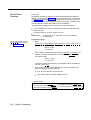
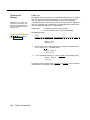
Dial Mode
Code: #201
Description: Identifies each outside line as either touch-tone or rotary.
Valid Entries:
1 = Touch-tone line
✔ 2 = Rotary line
Considerations: If you are using touch-tone phones on rotary lines, you may
need to adjust the Rotary Dialing Timeout (#108).
Programming Steps:
[ x ] [ x ] [ x ] [ x ] stand for the Sys-
tem Programming Password.
See procedure #110.
1. Press:
[ Feature ] [ 0 ] [ 0 ] [ System Program ] [ System Program ] [ x ] [ x ] [ x ] [ x ] [ # ] [ 2 ] [ 0 ] [ 1 ] .
The display reads:
Dial Mode
Line:
2. Enter the first line to be programmed. For example, to program line 8,
press [ 8 ] . The display reads:
Dial Mode L8
2 Rotary
3. To change the dial mode, press [ Next Data ] . The display reads:
Dial Mode L8
1 Touch Tone
To program another line, press [ Next Item ] or [ Prev Item ] until the correct line
number shows on the display. Follow step 3 to change the dialing mode.
Repeat for all lines that you want to change.
3-12
System Programming
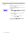
Line Type
Code: #202
Description: Identifies each outside line as being connected to the local telephone company or to a PBX system.
Valid Entries: ✔ 1 = CO (local telephone company line)
2 = PBX line
NOTE:
If any lines are connected to a PBX system, use procedure #106, PBX Dial-Out
Code, to identify the PBX dial-out code.
[ x ] [ x ] [ x ] [ x ] stands for the Sys-
tem Programming Password.
See procedure #110.
Programmi ng Steps:
1. Press:
[ Feature ] [ 0 ][ 0 ] [ System Program ] [ System Program ] [ x ] [ x ] [ x ] [ x ] [ # ] [ 2 ] [ 0 ] [ 2 ]
.
The display reads.
Line Type
Line:
2 . Enter the first line to be programmed. For example, to program line 1,
press [ 1 ] . The display reads:
Line Type L1
1 CO
3 . To change the line type, press [ Next Data ] . The display reads:
Line Type L1
2 PBX
To program another line, press [ Next Item ] or [ Prev Item ] until the correct line
number shows on the display. Follow step 3 to change the line type. Repeat for
every line in the system.
✔ = Factory Setting
To go to a specific procedure: [ # ] [ x ] [ x ] [ x ]
To go to the next procedure: [ Next Proc ]
To go to the previous procedure: [ Prev Proc ] (where X X X is the Procedure number)
To return data to the factory setting: [ Remove ] To exit system programming: [ Feature ] [ 0 ] [ 0 ]
System Programming
3-13
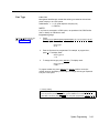
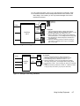
Line Assignment
Code: #301
Description: Use this procedure to change the line assignments on specific
extensions. These changes include adding lines, deleting lines, and setting the
order of the lines on a PARTNER phone’s line buttons.
Valid Entries: ✔ 1 = Assigned
2 = Not assigned
Hotline and doorphone extensions should not have outside
lines assigned to them, to
prevent calls from being made or
received on them.
Art: Put the button figure here
Considerations: Use this procedure to fine tune the number of lines you
assigned to all extensions through procedure #104, Number of Lines. For
example, if you assigned 5 lines to all extensions and there are 8 lines in the
system, use procedure #301 to assign lines 6, 7, and 8 to specific extensions.
Programming Notes: When you use procedure #301 to assign a line to an
extension with a PARTNER phone, the line goes to the first unused line button on
the phone. The order in which line buttons are assigned appears at the left. For
example, if the extension has no lines assigned to it and you assign line 4 first,
that line is put on line button A. If the extension had two other lines already
assigned to it, line 4 would be put on line button C.
To change the order of existing line assignments, first unassign the lines and
then reassign them in the desired order.
Programming Steps:
Assigning lines to particular line
buttons is useful for grouping
similar lines on adjacent line buttons (such as D and H).
Assign only as many lines to an
extension as that extension can
use. For example, a PARTNER
6-button phone can have only
four outside lines.
1. Press:
[ Feature ] [ 0 ] [ 0 ] [ System Program ] [ System Program ] [ x ] [ x ] [ x ] [ x ] [ # ] [ 3 ] [ 0 ] [ 1 ] .
The display reads:
LineAssign
Extension:
2. Enter the extension number to be programmed (10 through 33). For
example, to program extension 15, press [ 1 ] [ 5 ] . The display reads:
LineAssign 15
Line:
[ x ] [ x ] [ x ] [ x ] stands for the Sys-
tem Programming Password.
See procedure #110.
3. Enter the line to be assigned or unassigned. For example, to select line 1,
press [ 1 ] . The display reads:
LineAssign 15 L1
1 Assigned
If you don’t want an extension to have the line, press [ Next Data ] . The
display reads
LineAssign 15 L1
2 Not Assigned
To program another line for this extension, press [ Next Item ] or [ Prev Item ] until the
correct line number shows on the display. Repeat step 3.
Label the line assignments on each PARTNER phone.
To program another extension, press [ Next Proc ] [ Prev Proc ] (or [ # ] [ 3 ] [ 0 ] [ 1 ] ), and
begin at step 2.
3-14
System Programming
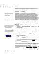
Line Use
Restriction
Restricting the use of a line is the
most extreme way to restrict dialing on the PARTNER Plus system. For example, an extension
with a line set to "in only" or “no
access," cannot select the line to
dial out, even emergency
numbers. There are other, less
extreme ways to restrict dialing.
See appendix A for a sunmary of
dialing restrictions.
Code: #302
Description: Use this procedure to restrict extensions from receiving and/or
making outside calls on specific lines. Since you program line use restrictions
for each line at each extension, you can restrict some lines on an extension
while not restricting others.
Valid Entries: ✔ 1 = No restriction (all calls permitted on that line)
2 = Out only (can only make outside calls, not receive them,
on that line)
3 = In only (can only receive calls, not make them, on that
line)
4 = No access (the line appears on the phone but cannot
receive or make calls; can receive transferred calls)
Programmi ng Steps:
1.
Press:
[ Feature ] [ 0 ] [ 0 ] [ System Program ] [ System Program ] [ x ] [ x ] [ x ] [ x ] [ # ] [ 3 ] [ 0 ] [ 2 ] .
[ x ] [ x ] [ x ] [ x ] stands for the Sys-
The display reads:
tem Programming Password.
See procedure #110.
Restrict
Extension:
2.
Enter the extension to be programmed. For example, to program extenion 23, press [ 2 ] [ 3 ] . The display reads:
Restrict 23
Line:
3.
Enter the line number to be restricted at this extension. For example, to
restrict line 2, press [ 2 ] . The display reads:
Restrict 23 L3
1 No Restriction
4.
To change the line restriction for this extension, enter the appropriate setting number listed above. For example, to restrict the line to incoming
calls, press [ 3 ] . The display reads:
Restrict 23 L3
3 In Only
To restrict another line at this extension, press [ Next Item ] or [ Prev Item ] until the line
number shows on the display. Repeat step 4.
To restrict another extension, press [ Next Proc ] [ Prev Proc ] (or [ # ] [ 3 ] [ 0 ] [ 2 ] ), and
begin at step 2.
✔ = Factory Setting
To go to a specific procedure: [ # ] [ x ] [ x ] [ x ]
To go to the next procedure: [ Next Proc ]
To go to the previous procedure: [ Prev Proc ] (where X X X is the procedure number)
To return data to the factory setting: [ Remove ] To exit system programming: [ Feature ] [ 0 ] [ 0 ]
System Programming
3-15
Display Language
Code: #303
If you change the language for
extension 10, the display rnessages imrnediately start appearing in the new language.
Description: Sets the language on the display of a PARTNER display phone.
The language is set for each extension, so phones on the same PARTNER systern can display different languages.
Valid Entries: ✔ 1 = English
2 = Spanish
3 = Italian
Programmi ng Steps:
[ x ] [ x ] [ x ] [ x ] stands for the Sys-
tem Programming Password.
See procedure #110.
1. Press:
[ Feature ] [ 0 ] [ 0 ] [ System Program ] [ System Program ] [ x ] [ x ] [ x ] [ x ] [ # ] [ 3 ] [ 0 ] [ 3 ] .
The display reads:
Language
Extension:
2. Enter the extension to be programmed. For example, to program extension 11, press [ 1 ] [ 1 ] . The display reads:
Language 11
1 English
3. To change the display language, enter the appropriate setting number as
listed above. For example, to change the display messages to Italian,
press [ 3 ] . The display reads:
Language 11
3 Italian
To change the display language for another extension, press [ Next Item ] or
[ Prev Item ] until the extension number shows on the display. Repeat step 3.
3-16
System Programming
Automatic Privacy
Code: #304
Description: Automatically prevents users with the same lines from joining
telephone conversations on a specific extension.
This feature is typically used for
extensions connected to fax
machines and modems, which
make and receive datas calls that
should not be interrupted.
Valid Entries:
1 = Assigned to extension
✔ 2 = Not assigned
Considerations: A user can override Automatic Privacy with the Privacy feature
(page 4-12).
Programmi ng Steps:
[ x ] [ x ] [ x ] [ x ] stands for the Sys-
tem Programming Password.
See procedure #110.
1 . Press:
[ Feature ] [ 0 ] [ 0 ] [ System Program ] [ System Program ] [ x ] [ x ] [ x ] [ x ] [ # ] [ 3 ] [ 0 ] [ 4 ] .
The display reads:
Auto Privacy
Extension:
2 . Enter the extension to be programmed. For example, to program extension 16, press [ 1 ] [ 6 ] . The display reads:
Auto Privacy 16
2 Not Assigned
3 . To assign Automatic Privacy to the extension, press [ Next Data ] until the
display reads:
Auto Privacy 16
1 Assigned
To program another extension, press [ Next Item ] or [ Prev Item ] until the extension
number shows on the display. Repeat step 3.
✔ = Factory Setting
To go to the next procedure: [ Next Proc ]
To go to the previous procedure: [ Prev Proc ]
To return data to the factory setting: [ Remove
To go to a specific procedure: [ # ] [ x ] [ x ] [ x ]
(where X X X is the procedure number)
To
exit system programming: [ Feature ] [ 0 ] [ 0 ]
]
System Programming
3-17
Abbreviated
Ringing
Receptionists, and others who
handle many calls quickly, often
leave Abbreviated Ringing off so
they have an audible reminder of
incoming calls.
Code: #305
Description: Use this procedure to turn Abbreviated Ringing on or off. When a
user is on a call and Abbreviated Ringing is on, an incoming call rings only
once. The light next to the line button flashes until the call is answered
or the caller hangs up. This feature prevents an incoming call from distracting a
user busy on another call. To allow calls to ring repeatedly at a specific extension, turn Abbreviated Ringing off for that extension.
Valid Entries
1 = Active/On (incoming calls ring once)
✔ 2 = Not active/Off (incoming calls ring repeatedly)
Programming Steps:
[ x ] [ x ] [ x ] [ x ] stands for the Sys-
tem Programming Password.
See procedure #110.
1. Press:
[ Feature ] [ 0 ] [ 0 ] [ System Program ] [ System Program ] [ x ] [ x ] [ x ] [ x ] [ # ] [ 3 ] [ 0 ] [ 5 ] .
The display reads:
Abbrev. Ring
Extension:
2 . Enter the extension to be programmed. For example, to program extension 12, press [ 1 ] [ 2 ] . The display reads:
Abbrev. Ring 12
2 Not Active
3.
To turn Abbreviated Ringing on, press [ Next Data ] until the display reads:
Abbrev. Ring 12
1 Active
To program another extension, press [ Next Item ] or [ Prev Item ] until the extension
number shows on the display. Repeat step 3.
3-18
System Programming
Joining a Call
Code: #306
Description: Allows or denies users to join an active call on an extension basis.
Even if a user’s extension allows joining calls, the user must first dial a feature
code ( [ Feature ] [ 1 ] [ 4 ] ) before the connection is completed. When another user
joins a call, the system notifies the other users with a brief tone.
If a person needs to join a call
but the extension does not allow
it, the other party must conference that person in on the call.
[ x ] [ x ] [ x ] [ x ] stands for the Sys-
tem Programming Password.
See procedure #110.
Valid Entries: ✔ 1 = Allowed
2 = Disallowed
Programming Steps:
1. Press:
[ Feature ] [ 0 ] [ 0 ] [ System Program ] [ System Program ] [ x ] [ x ] [ x ] [ x ] [ # ] [ 3 ] [ 0 ] [ 6 ] .
The display reads
Bridging
Extension:
2. Enter the extension to be programmed. For example, to program extension 13, press [ 1 ] [ 3 ] . The display reads:
Bridging 13
1 Allowed
3. To prevent users on this extension from joining calls, press [ Next Data ] until
the display reads:
Bridging 13
2 Disallowed
To program another extension, press [ Next Item ] or [ Prev Item ] until the extension
number shows on the display. Repeat step 3.
✔ = Factory Setting
To go to a specific procedure: [ # ] [ x ] [ x ] [ x ]
To go to the next procedure: [ Next Proc ]
To go to the previous Procedure: [ Prev Proc ] (where X X X is the procedure number)
To return data to the factory setting: [ Remove ] To exit system programming: [ Feature ] [ 0 ] [ 0 ]
System Programming
3-19
Call Waiting
Code: #307
Call waiting will not work on a
standard phone that is in a combination extension with a system
phone.
Description: For extensions having standard telephones (but not in combination with a system phone), the Call Waiting feature sends a tone to notify a user
talking on the phone of another incoming call. The call waiting tone works for
standard telephones in two situations: 1) when Night Service is on and a call
comes in to an extension in the Night Service group; and 2) when a call is
transferred to the extension. The user can answer the call by doing a
switchhook flash (putting the active call on hold) or the user can hang up and
end the current call, then answer the incoming call.
Valid Entries: ✔ 1 = Allowed
2 = Disallowed
Considerations:
For Call Waiting to work when Night Service is on, make sure extensions with
basic telephones are members of the Night Service Group (#504).
To avoid corrupting data transmissions, do not allow Call Waiting on extensions with credit card scanners, modems, and fax machines.
Programming Steps:
[ x ] [ x ] [ x ] [ x ] stand for the Sys-
tem Programming Password.
See procedure #110.
1. Press:
[ Feature ] [ 0 ] [ 0 ] [ System Program ] [ System Program ] [ x ] [ x ] [ x ] [ x ] [ # ] [ 3 ] [ 0 ] [ 7 ] .
The display reads:
Call Waiting
Extension:
2 . Enter the extension to be programmed. For example, to program extension 14, press [ 1 ] [ 4 ] . The display reads:
Call Waiting 14
1 Allowed
3 . To prevent the call waiting tone, press [ Next Data ] until the display reads:
Call Waiting 14
2 Disallowed
To program another extension press [ Next Item ] or [ Prev Item ] until the extension
number shows on the display. Repeat step 3.
3-20
System Programming
Copy Settings
Code: #399
Description: Copies the following settings from any extension to any other
extension:
#301 Line Assignment
#405 Disallowed List Assignment
#408 Allowed List Assignment
#302 Line Use Restriction
#303 Display Language
#501 Pickup Group Extensions
#304 Automatic Privacy
#502 Calling Group Extensions
#504 Night Service Group
#305 Abbreviated Ringing
#306 Joining a Call
#601 Fax Machine Extensions
#307 Call Waiting
Automatic Line Selection (page 4-6)
#401 Outgoing Call Restrictions
Line Ringing Options (page 4-7)
Valid Entries: Any valid source extension number (the extension copied from)
and any valid target extension number (the extension copied to)
Programming Notes: This procedure is skipped in the sequence of programming procedures. To use this procedure, enter the procedure code directly
(see step 1).
Programming Steps:
[ x ] [ x ] [ x ] [ x ] stands for the Sys-
tem Prograrnming Password.
See procedure #110.
1.
Press:
[ Feature ] [ 0 ] [ 0 ] [ System Program ] [ System Program ] [ x ] [ x ] [ x ] [ x ] [ # ] [ 3 ] [ 0 ] [ 9 ] .
The display reads:
Copy
Extension:
2. Enter the extension to copy from. For example, to copy extension 18,
press [ 1 ] [ 8 ] . The display reads:
Copy 18
Data --
3 . Enter the extension to copy to. Any extension except the source extension
is valid. For example, to copy to extension 22, press [ 2 ] [ 2 ] . The display
reads:
Copy 18
Data 22
To copy the same settings to another extension, enter the new extension
number.
To copy another extension’s settings, press [ Next Item ] or [ Prev Item ] until the extension shows on the display. Repeat step 3.
✔ = Factory Setting
To go to a specific procedure: [ # ] [ x ] [ x ] [ x ]
To go to the next procedure: [ Next Proc ]
To go to the previous procedure: [ Prev Proc ] (where X X X is the procedure number)
To return data to the factory setting: [ Remove ] To exit system programming: [ Feature ] [ 0 ] [ 0 ]
System Programming
3-21
Outgoing Call
Restrictions
See appendix A for a complete
summary of dialing restrictions.
Code: #401
Description: Restricts the types of calls an extension can make. An extension
can be restricted to inside calling only, or to local and inside calling. Outgoing
Call Restrictions apply to all lines assigned to the extension. The System Password (#403), Emergency Phone Number List (#406), Disallowed and Allowed
Phone Number Lists (#404 and #407) override Outgoing Call Restrictions.
Valid Entries: ✔ 1 = No restriction (can make toll, local, and inside calls)
2 = Inside only (can make inside calls only)
3 = Local only (can make outside calls
that do not begin with zero, and inside
calls only)
Considerations: While procedures that restrict dialing are very effective, absolute protection against misuse cannot be guaranteed. PARTNER phones give
you more protection against such misuse than standard phones. Therefore, we
strongly recommend that you install PARTNER phones where restricting phone
use is important.
Programming Steps:
[ x ] [ x ] [ x ] [ x ] stands for the Sys-
tem Programming Password.
See procedure #110.
1. Press:
[ Feature ] [ 0 ] [ 0 ] [ System Program ] [ System Program ] [ x ] [ x ] [ x ] [ x ] [ # ] [ 4 ] [ 0 ] [ 1 ] .
The display reads:
Call Restrict
Extension:
2. Enter the extension to be programmed. For example, to select extension
30, press [ 3 ] [ 0 ] . The display reads:
Call Restrict 30
1 No Restriction
3. To change the type of call restriction, enter the appropriate setting number
as listed-above. For example, to restrict this extension to local and intercom calling, press [ 3 ] . The display reads:
Call Restrict 30
3 Local Only
To program another extension, press [ Next Item ] or [ Prev Item ] untiI the extension
number shows on the display. Repeat step 4.
3-22
System Programming
System Password
Code: #403
Description: Identifies the 4-digit password that lets a user override Outgoing
Call Restrictions (#401). You can also use the password with Night Service
(#503 and #504) to restrict after-hours dialing.
Valid Entries: Any 4 digits
Entering the password allows you
to override several dialing restrictions. See appendix A for a summary of dialing restrictions.
Considerations: If you assign a password using this procedure, you must enter
the password when turning Night Service (#503) on or off.
Programming Steps:
1. Press:
[ x ] [ x ] [ x ] [ x ] stands for the Sys-
tem Programming Password.
See procedure #110.
[ Feature ] [ 0 ] [ 0 ] [ System Program ] [ System Program ] [ x ] [ x ] [ x ] [ x ] [ # ] [ 4 ] [ 0 ] [ 3 ] .
The display reads:
Set Password
Data----
If a password has previously been set, it will appear on the display.
2. Enter or change the password using the dial pad. For example, to set the password to 5747, press [ 5 ] [ 7 ] [ 4 ] [ 7 ] . The display reads:
Set Password
Data5747
To remove a password, press [ Remove ] .
✔ = Factory Setting
To go to the next procedure: [ Next Proc ]
To go to a specific procedure: [ # ] [ x ] [ x ] [ x ]
To go to the previous procedure: [ Prev Proc ] (where X X X is the procedure number)
To return data to the factory setting: [ Remove ] To exit system programming: [ Feature ] [ 0 ] [ 0 ]
System Programming
3-23
Disallowed
Phone Number
Lists
See appendix A for a summary of
dialing restrictions.
Code: #404
Description: Specifies telephone numbers that users cannot dial. For example,
you may want to prevent calls to a specific telephone number or to categories of
numbers, such as international numbers. Use this procedure to create up to
four lists of up to 10 telephone numbers each. Then use procedure #405,
Disallowed List Assignment, to assign the lists to specific extensions.
Valid Entries:
List numbers 1 to 4
Maximum 10 telephone numbers per list
Maximum 22 digits per telephone number
Wildcard character (!) to match any single digit
Programming Notes: To program telephone numbers, dial the number as you
would normally. You can also use the “wildcard” character to stand for any digit
in a phone number. To use the wildcard, press [ Wild ] . The wildcard character
appears as a “!” on the display.
Programming Steps:
[ x ] [ x ] [ x ] [ x ] stands for the
System Programming Password.
See procedure #110.
1.
Press:
[ Feature ] [ 0 ][ 0 ] [ System Program ] [ System Program ] [ x ] [ x ] [ x ] [ x ] [ # ] [ 4 ] [ 0 ] [ 4 ] .
The display reads
DisallowLst
List No:
2.
Enter the list to be set up (1 through 4). For example, to select list 1, press
[ 1 ] . The display reads:
DisallowLst 1
Entry:
3.
Select a list entry (01 through 10). For example, to select entry 01, press
[ 0 ] [ 1 ] . The display reads:
DisallowLst 1 01
Data ------------
4.
Enter the first telephone number. For example, to prevent calls to 976,
press [ 9 ] [ 7 ] [ 6 ] . The display reads:
DisallowLst 1 01
Data976
5. To save the telephone number in memory, press [ Enter ] .
To enter other phone numbers in this list, press [ Next Item ] and repeat steps
4 and 5.
To change a phone number, press [ Remove ] and repeat steps 4 and 5.
To delete a phone number, press [ Remove ] .
To create another list, press [ # ] [ 4 ] [ 0 ] [ 4 ] and start at step 2 above.
3-24
System Programming
Disallowed List
Assignment
Code: #405
Description: After creating Disallowed Phone Number Lists (#404), use this
procedure to assign them to specific extensions. For example, you can assign
list 1 to extensions 27 and 28, and list 2 to extension 28 only.
Valid Entries:
[ x ] [ x ] [ x ] [ x ] stands for the Sys-
tem Programming Password.
See procedure #110.
1 = Assigned to extension
✔ 2 = Not assigned to extension
Programming Steps:
1. Press:
[ Feature ] [ 0 ] [ 0 ] [ System Program ] [ System Program ] [ x ] [ x ] [ x ] [ x ] [ # ] [ 4 ] [ 0 ] [ 5 ] .
The display reads:
DisallowTo
Extension:
2. Enter the extension to be programmed. For example, to program extension 27, press [ 2 ] [ 7 ] . The display reads:
DisallowTo
List No:
27
3. Enter the list to be assigned to the extension. For example, to select list 1,
press [ 1 ] . The display reads:
DisallowTo 27 1
2 Not Assigned
4. To assign the list, press [ Next Data ] until the display reads:
DisallowTo 27 1
1 Assigned
5. To assign another list to this extension, press [ Next Item ] or [ Prev Item ] until the
list number shows on the display. Repeat step 4.
To program another extension, press [ Next Proc ] [ Prev Proc ] (or [ # ] [ 4 ] [ 0 ] [ 5 ] ), and
begin at step 2.
✔ = Factory Setting
To go to a specific procedure: [ # ] [ x ] [ x ] [ x ]
To go to the next procedure: [ Next Proc ]
To go to the previous procedure: [ Prev Proc ] (where X X X is the procedure number)
To return data to the factory setting: [ Remove ] To exit system programming: [ Feature ] [ 0 ] [ 0 ]
System Programming
3-25
Emergency
Phone Number
List
See appendix A for a summary of
dialing restrictions.
Code: #406
Description: Specifies emergency telephone numbers that can be dialed from
any extension regardless of other dialing restrictions, except Line Use Restriction (#302).
Valid Entries: 10 telephone numbers, 1 to 22 digits each
Programming Notes: The emergency list can contain specific telephone
numbers or categories of telephone numbers. See Disallowed Phone Number
Lists (#404) for detailed instructions on programming telephone numbers.
Typical list entries include:
Emergency public services
Fire
Police
IMPORTANT: When programming emergency numbers and/or making test
calls to emergency numbers:
1. Remain on the line and briefly explain to the dispatcher the reason for the
call before hanging up.
2. Perform such activities in the off-peak hours, such as early morning or late
evening.
Programming Steps:
[ x ] [ x ] [ x ] [ x ] stands for the Sys-
tem Programming Password.
See procedure #110s.
1. Press:
[ Feature ] [ 0 ] [ 0 ] [ System Program ] [ [ System Program ] [ x ] [ x ] [ x ] [ x ] [ # ] [ 4 ] [ 0 ] [ 6 ] .
The display reads:
EmergencyList
Entry:
2. Select a list entry (01 through 10). For example, to select entry 03, press
[ 0 ] [ 3 ] . The display reads:
EmergencyList 03
Data ------------
3. Enter the telephone number. For example, press [ 4 ] [ 1 ] [ 1 ] . The
display reads:
EmergencyList
Data411
03
To select another list entry, press [ Next Item ] or [ Prev Item ] until the new entry
number shows on the display. Repeat step 3.
TO correct an incorrect telephone number, press [ Remove ] and enter the correct
phone number.
To delete a telephone number, press [ Remove ] .
3-26
System Programming
Allowed
Phone Number
Lists
See appendix A for a summary of
dialing restrictions.
Code: #407
Description: Specifies telephone numbers that users can dial regardless of
other dialing restrictions. For example, if you restrict an entire category of call
through Disallowed Phone Number Lists (#404), you can permit calls to a
specific number in that category by placing that number on an allowed list.
Using this procedure, you can create up to four lists of up to 10 telephone
numbers each. Use procedure #408 (Allowed List Assignment) to assign the
lists to specific extensions.
Valid Entries:
List numbers 1 to 4
Maximum 10 telephone numbers per list
Maximum 22 digits per telephone number
Wildcard character(!) to match any single digit
Programming Steps:
[ x ] [ x ] [ x ] [ x ] stands for the Sys-
tem Programming Password.
See procedure #110.
1. Press:
[ Feature ] [ 0 ] [ 0 ] [ System Program ] [ System Program ] [ x ] [ x ] [ x ] [ x ] [ # ] [ 4 ] [ 0 ] [ 7 ]
The display reads:
AllowList
List No:
2.
Selecting lists and entering phone numbers is the same for this procedure
as for Disallowed Phone Number Lists (#404). See page 3-24 for instructions on creating lists of phone numbers.
✔ = Factory Setting
To go to a specific procedure: [ # ] [ x ] [ x ] [ x ]
To go to the next procedure: [ Next Proc ]
To go to the previous procedure: [ Prev Proc ] (where X X X is the procedure number)
To return data to the factory setting: [ Remove ] To exit system programming: [ Feature ] [ 0 ] [ 0 ]
System Programming
3-27
.
Allowed List
Assignment
Code: #408
Description: After creating Allowed Phone Number Lists (#407), use this procedure to assign them to specific extensions. For example, you can assign list 1
to extensions 17 and 18, and list 2 to extension 18 only.
Valid Entries:
1 = Assigned to extension
✔ 2 = Not assigned to extension
Programming Steps:
[ x ] [ x ] [ x ] [ x ] stands for the Sys-
tem Programming Password.
See procedure #110.
1. Press:
[ Feature ] [ 0 ] [ 0 ] [ System Program ] [ System Program ] [ x ] [ x ] [ x ] [ x ] [ # ] [ 4 ] [ 0 ] [ 8 ] .
The display reads:
AllowTo
Extension:
2. Selecting extensions and lists for for this procedure is the same as for
Disallowed List Assignment (#405). See page 3-25 for instructions on
assigning lists to extensions.
3-28
System Programming
Pickup Group
Extensions
You can answer calls to the
Pickup Group with one touch by
programming if on a button. See
page 4-15.
[ x ] [ x ] [ x ] [ x ] stands for the Sys-
tem Programming Password.
See procedure #110.
Code: #501
Description: Identifies the extensions in the Pickup Group-the group of
extensions whose outside calls can be answered by any extension on the system. When an outside call rings at an extension in the Pickup Group, any other
extension on the system can answer the ringing line by pressing [ Intercom ] [ 6 ] [ 6 ] .
The system automatically connects the call to the extension, even though the
extension may not be in the group and may not have that line assigned to it.
The Pickup Group feature is useful when an extension needs to answer calls on
lines not assigned to that phone. For example, during lunch, one person may
be designated
to answer all calls that come into the Pickup Group.
—
Valid Entries:
✔ 1 = Assigned (extension is in the Pickup Group)
2 = Not assigned (extension is not in the Pickup Group)
Considerations: The system can have only one Pickup Group.
Programming Steps:
1. Press:
[ Feature ] [ 0 ] [ 0 ] [ System Program ] [ System Program ] [ x ] [ x ] [ x ] [ x ] [ # ] [ 5 ] [ 0 ] [ 1 ] .
The display reads:
Pickup Group
Extension:
2. Enter the extension to be programmed. For example, to program extension 29, press [ 2 ] [ 9 ] . The display reads:
Pickup Group 29
1 Assigned
3
To remove the extension from the group, press [ Next Data ] until the display
reads:
Pickup Group 29
2 Not Assigned
To program another extension, press [ Next Item ] or [ Prev Item ] until the extension
number shows on the display. Repeat step 3.
✔ = Factory Setting
To go to a specific procedure: [ # ] [ x ] [ x ] [ x ]
To go to the next procedure: [ Next Proc ]
To go to the previous procedure: [ Prev Prod ] (where X X X is the procedure number)
To return data to the factory setting: [ Remove ] To exit system programming: [ Feature ] [ 0 ] [ 0 ]
System Programming
3-29
Calling Group
Extensions
Code: #502
Description: Identifies the extensions in the Calling Group-the group of extensions that can be called at the same time. Any user on the system can ring all
the phones in the Calling Group by dialing [ Intercom ] [ 7 ] [ 1 ] . Users can also voice
signal the phones in the Calling Group by dialing [ Intercom ] [ * ] [ 7 ] [ 1 ] (or [ 7 ] [ 9 ]
[ 7 ] [ 1 ] from rotary phones). This feature is useful for conversing with or transferring calls to a group of users such as a sales pool.
Valid Entries: ✔ 1 = Assigned (extension in the Calling Group)
2 = Not assigned (extension not in the Calling Group)
Considerations:
The system can have only one Calling Group.
Do not assign extensions with fax machines, answering machines, hotline
phones, and doorphones to the Calling Group.
Programming Steps:
[ x ] [ x ] [ x ] [ x ] stands for the Sys-
tem Programming Password.
See procedure #110.
1.
Press:
[ Feature ] [ 0 ] [ 0 ] [ System Program ] [ System Program ] [ x ] [ x ] [ x ] [ x ] [ # ] [ 5 ] [ 0 ] [ 2 ] .
The display reads:
Calling Group
Extension:
2.
Enter the extension to be programmed. For example, to select extension
31, press [ 3 ] [ 1 ] . The display reads:
Calling Group 31
1 Assigned
3.
To remove the extension from the group, press [ Next Data ] until the display
reads
Calling Group 31
2 Not Assigned
To program another extension, press [ Next Item ] or [ Prev Item ] until the extension
number shows on the display. Repeat step 3.
3-30
System Programming
Night Service Button
Code: #503
Description: To use the Night Service feature, you must program it onto the
PARTNER display phone at extension 10. This procedure assigns Night Service
to the second programmable feature button with lights. Figure 4-1 on page 4-2
shows the location of the Night Service button.
Night Service is useful if you want
all phones to ring after hours.
For example, the Shipping
Department does not answer
calls during the day, but after
hours you want them to answer
incoming calls.
Night Service with a System
Password is useful for controlling
unauthorized use of phones after
hours.
To turn Night Service on and off, simply press the Night Service button. When
Night Service is on, all lines ring immediately, regardless of their normal Line
Ringing Options (see page 4-7). Night Service affects only the extensions in the
Night Service Group. Use procedure #504 to setup the Night Service Group.
Valid Entries:
1 = Night Service assigned
✔ 2 = Night Service not assigned
Considerations: If you programmed a System Password (#403), you must enter
the password when turning Night Service on or off. In addition, when Night Service is on, users in the Night Service Group can dial only Emergency Numbers
(#406) and Marked System Speed Dial Numbers (page 3-40) without entering
the System Password.
Programming Notes:
This procedure erases any feature or Auto Dial number you may have previously programmed onto the Night Service button.
If Night Service is assigned, you cannot program another feature on this button, unless you remove Night Service first.
A Night Service button can be programmed only for extension 10.
Programming Steps:
[ x ] [ x ] [ x ] [ x ] stands for the Sys-
tem Programming Password.
See procedure #110.
1. Press:
[ Feature ] [ 0 ] [ 0 ] [ System Program ] [ System Program ] [ x ] [ x ] [ x ] [ x ] [ # ] [ 5 ] [ 0 ] [ 3 ] .
The display reads:
Night Service
2 Not Assigned
2. To program Night Service onto the Night Service button, press [ Next Data ]
until the display reads:
Night Service
1 Assigned-Ext 10
3.
Label the Night Service button on extension 10.
✔ = Factory Setting
To go to a specific procedure: [ # ] [ x ] [ x ] [ x ]
To go to the next procedure: [ Next Proc ]
To go to the previous procedure: [ Prev Proc ] (where X X X is the procedure number)
To return data to the factory setting: [ Remove ] To exit system programming: [ Feature ] [ 0 ] [ 0 ]
System Programming
3-31
Night Service Group
Code: #504
Standard phones that are not
assigned to the Night Service
Group will still have Call Waiting
on transfered calls.
Description: Identifies the extensions in the Night Service Group. When Night
Service is on and a call comes in, all extensions in the Night Service Group ring
immediately or users with standard phones go to Call Waiting if busy. In addition, restricted Night Service (when the system has a password) limits the Night
Service Group extensions to dialing only numbers on the Emergency Phone
Number List (#403) and Marked System Speed Dial Numbers (page 3-40).
Valid Entries : ✔ 1 = Extension is in the group
2 = Extension is not in the group
Considerations: Do not include hotline extensions in the Night Service Group.
[ x ] [ x ] [ x ] [ x ] stands for fhe Sys-
tem Programming Password.
See procedure #110.
Programming Steps:
1. Press:
[ Feature ] [ 0 ] [ 0 ] [ System Program ] [ System Program ] [ x ] [ x ] [ x ] [ x ] [ # ] [ 5 ] [ 0 ] [ 4 ] .
The display reads:
NS Group
Extension:
2. Enter the extension to be programmed. For example, to program extension 13, press [ 1 ] [ 3 ] . The display reads:
NS Group 13
1 Assigned
3.
To remove the extension from the group, press [ Next Data ] until the display
reads:
NS Group 13
2 Not Assigned
TO program another extension, press [ Next Item ] or [ Prev Item ] until the extension
number shows on the display. Repeat step 3.
3-32
System Programming
Fax Machine
Extensions
Code: #601
Description: If you have a fax machine connected to the system and want to
monitor its status with a Fax Management button (see chapter 6) use this procedure to identify the fax extension.
Valid Entries:
1 = Extension assigned
✔ 2 = Etension not assigned
Considerations:
■
To prevent other extensions from interrupting a fax call, program the fax
extension for Automatic Privacy (#304) and turn Call Waiting (#307) off.
Programming Steps:
[ x ] [ x ] [ x ] [ x ] stands for the Sys-
tem Programming Password.
See procedure #110.
1. Press:
[ Feature ] [ 0 ] [ 0 ] [ System Program ] [ System Program ] [ x ] [ x ] [ x ] [ x ] [ # ] [ 6 ] [ 0 ] [ 1 ] .
The display reads:
Facsimile
Extension:
2. Enter the extension to be programmed. For example, to select extension
30, press [ 3 ] [ 0 ] . The display reads:
Facsimile 30
2 Not Assigned.
3. To identify the extension as a fax machine, press [ Next Data ] until the
display reads:
Facsimile 30
1 Assigned
To program another extension, press [ Next Item ] or [ Prev Item ] until the extension
number shows on the display. Repeat step 3.
✔ = Factory Setting
To go to the next procedure: [ Next Proc ]
To go to a specific procedure: [ # ] [ x ] [ x ] [ x ]
To go to the previous procedure: [ Prev Proc ] (where X X X is the procedure number)
To return data to the factory setting: [ Remove ] To exit system programming: [ Feature ] [ 0 ] [ 0 ]
System Programming
3-33
Music On Hold
Code: #602
Description: Activates or deactivates the Music-on-Hold jack on the processor
module. To provide music or taped messages to callers on hold, the Music-onHold jack must be active and an audio source attached to the jack.
Valid Entries:
1 = Active
✔ 2 = Not Active
Considerations:
If the audio source develops trouble (such as a bad tape), you can quickly
turn it off by setting the jack to “not active” until you are able to solve the
problem.
Users of equipment that rebroadcasts copyrighted music or other material
may be required to obtain a license from a third party such as ASCAP or
BMI.
If Music-On-Hold is not active callers on hold hear a repeating tone.
Programming Steps:
1. Press:
[ x ] [ x ] [ x ] [ x ] stands for the Sys-
tem Programming Password.
See procedure #110.
[ Feature ] [ 0 ] [ 0 ] [ System Program ] [ System Program ] [ x ] [ x ] [ x ] [ x ] [ # ] [ 6 ] [ 0 ] [ 2 ] .
The display reads:
Music On Hold
2 Not Active
2. To activate the music-on-hold jack press [ Next Data ] until the display reads:
Music On Hold
1 Active
✔ = Factory Setting
To go to a specific procedure: [ # ] [ x ] [ x ] [ x ]
To go to the next procedure: [ Next Proc ]
To go to the previous procedure: [ Prev Proc ] (where X X X is the procedure number)
To return data to the factory setting: [ Remove ] To exit system programming: [ Feature ] [ 0 ] [ 0 ]
3-34
System Programming
Hotline
Code: #603
Description: Identifies the “hotline” extension and the extension it automatically
rings (the “alert” extension). When someone lifts the handset of the hotline telephone, the alert extension rings. You can set up several hotline and alert extension pairs. The alert extension can be the same or different for one or more hotline extensions.
Valid Entries:
✔
A hotline extension
An alert extension
No hotline or alert assigned
Considerations:
The hotline telephone must be a standard, single-line touch-tone or rotary
telephone.
A hotline cannot be a doorphone. Assigning a hotline to a doorphone extension cancels the doorphone setting.
To prevent outside calls from being made or received on the hotline, use
Line Assignment (#301 ) to remove all outside lines from the hotline extension.
Include only intercoms in the Automatic Line Selection for the hotline extension (page 4-6).
Remove hotline extensions from the Night Service Group (#504) and Calling
Group (#502).
Do not program hotlines on power failure extensions (10, 11, 16, 17,22,23,
28, 29).
Programming Notes: When programming the hotline, you first enter the hotline
extension and then the alert extension. Enter the hotline and alert extensions as
different extensions. Extension 10 cannot be a hotline extension (although it can
be an alert extension).
Programming Steps:
[ x ] [ x ] [ x ] [ x ] stands for the Sys-
tem Programming Password.
See procedure #110.
1. Press:
[ Features ] [ 0 ] [ 0 ] [ System Program ] [ System Program ] [ x ] [ x ] [ x ] [ x ] [ # ] [ 6 ] [ 0 ] [ 3 ] .
The display reads:
Hot Line
Extension:
2. Enter the hotline extension(11 through 33). For example, to program
extension 33 as the hotline, press [ 3 ] [ 3 ] . The display reads:
Hot Line 33
Data --
3. Enter the alert extension (10 through 33). For example, to use extension
32 as the alert extension, press [ 3 ] [ 2 ] . The display reads:
Hot Line 33
Data 32
To program another hotline, press [ Next Item ] or [ Prev Item ] until the new hotline
extension number shows on the display. Repeat step 3.
System Programming
3-35
Doorphone 1
Extension
A doorphone consists of a
speaker and a button. It is usually placed near an entrance for
screening visitors.
Code: #604
Description: You can connect up to two doorphones to the PARTNER Plus
system. Each doorphone can ring up to five other “alert” extensions. Use this
procedure to identify the extension to which the first doorphone is connected.
Use procedure #605 to identify the second doorphone extension. Use procedure #606 to assign the alert extensions for both doorphones.
Valid Entries:
Extensions 12, 13, 14, 15, 18, 19, 20,21,24,25,26,27,
30,31,32,33
✔ None assigned
Considerations: A doorphone extension cannot be a hotline extension at the
same time. Assigning a doorphone on a hotline (or other doorphone) extension
cancels the hotline (or doorphone) programming. However, hotlines and doorphones can have the same alert extensions.
Programming Steps:
[ x ] [ x ] [ x ] [ x ] stands for the Sys-
tem Programming Password.
See procedure #110.
1. Press:
[ Feature ] [ 0 ] [ 0 ] [ System Program ] [ System Program ] [ x ] [ x ] [ x ] [ x ] [ # ] [ 6 ] [ 0 ] [ 4 ] .
The display reads:
Door Phone 1
Data --
2. Enter the doorphone extension. For example, to select extension 20,
press [ 2 ] [ 0 ] . The display reads:
Door Phone 1
Data 20
3-36
System Programming
Doorphone 2
Extension
Code: #605
Description: See the description for Doorphone 1 Extension (#604), above.
Doorphone 2 has a different ring from Doorphone 1.
Valid Entries:
Extensions 12, 13, 14, 15, 18, 19, 20, 21, 24, 25, 26, 27,
30,31,32,33
✔ None assigned
Considerations: See the considerations for Doorphone 1 Extension (#604).
Programming Steps:
[ x ] [ x ] [ x ] [ x ] stands for the Sys-
tem Programming Password.
See procedure #110.
1. Press:
[ Feature ] [ 0 ] [ 0 ] [ System Program ] [ System Program ] [ x ] [ x ] [ x ] [ x ] [ # ] [ 6 ] [ 0 ] [ 5 ] .
The diplay reads:
Door Phone 2
Data --
2. Enter the doorphone extension. For example, to select extension 21,
press [ 2 ] [ 1 ] . The display reads:
Door Phone 2
Data 21
✔ = Factory Setting
To go to a specific procedure: [ # ] [ x ] [ x ] [ x ]
To go to the next procedure: [ Next Proc ]
To go to the previous procedure: [ Prev Proc ] (where X X X is the procedure number)
To return data to the factory setting: [ Remove ] To exit system programming: [ Feature ] [ 0 ] [ 0 ]
System Programming
3-37
Doorphone
Alert
Extensions
Code: #606
Description: Identifies the extension or extensions that ring when someone
presses the button on a doorphone. Each doorphone can have up to five alert
extensions. The doorphones can have five individual alert extensions or they
can share alert extensions. Use procedures #604 and #605 (Doorphone 1 and
Doorphone 2 Extensions) to assign doorphone extensions.
Valid Entries:
✔ 1 = Not an alert extension
2 = Doorphone 1 alert extension
3 = Doorphone 2 alert extension
4 = Both doors alert extension
Programming Steps:
[ x ] [ x ] [ x ] [ x ] stands for the System Programming Password.
See procedure #110.
1. Press:
[ Feature ] [ 0 ] [ 0 ] [ System Program ] [ System Program ] [ x ] [ x ] [ x ] [ x ] [ # ] [ 6 ] [ 0 ] [ 6 ] .
The display reads:
DoorPhneAlert
Extension:
2. Enter the first alert extension. For example, to select extension 10, press
[ 1 ] [ 0 ] . The display reads:
DoorPhneAlert
1 No Alert
10
3. To change the alert status, enter the appropriate setting as listed above.
For example, to make this extension an alert for both doorphone extensions, press [ 4 ] . The display reads:
DoorPhneAlert 10
4 Doors 1 and 2
TO select another alert extension, press [ Next Item ] or [ Prev Item ] until the extension
number shows on the display. Repeat step 3.
3-38
System Programming
SMDR Output
Code: #607
SMDR requires special hardware.
See page 1-5.
Description: Station Message Detail Recording (SMDR) provides detailed
tracking of telephone usage in a printed report. This procedure allows you to
specify what information is to be included on the printed report.
Valid Entries :
✔ 1 = All outgoing calls
2 = All outgoing and incoming calls
3 = Outgoing calls with pulses
4 = Outgoing calls with pulses and all incoming calls
Considerations:
For entries 3 and 4 above, you must have the Pulse Metering option.
To ensure that the correct time and date appears on the SMDR, set them
correctly using #101 and #103.
Programmi ng Steps:
[ x ] [ x ] [ x ] [ x ] stands for the Sys-
tem Programming Password.
See procedure #110.
1. Press:
[ Feature ] [ 0 ] [ 0 ] [ System Program ] [ System Program ] [ x ] [ x ] [ x ] [ x ] [ # ] [ 6 ] [ 0 ] [ 7 ] .
The display reads:
SMDR Records
1 out calls
2. To change the contents of the SMDR report, enter the appropriate setting
number as listed above. For example, to change the report output to
include all outgoing and incoming calls, press [ 2 ] .
SMDR Records
2 All calls
IMPORTANT: If you press [ Next Proc ], the system skips procedure #728, System Reset—Programming Saved and returns to procedure #101, System Date.
To use procedure #728 at this point, you must enter [ # ] [ 7 ] [ 2 ] [ 8 ] .
✔ = Factory Setting
To go to a specific procedure: [ # ] [ x ] [ x ] [ x ]
To go to the next procedure: [ Next Proc ]
To go to the previous procedure: [ Prev Proc ] (where X X X is the procedure number)
To return data to the factory setting: [ Remove ] To exit system programming: [ Feature ] [ 0 ] [ 0 ]
System Programming
3-39
System Reset—
Programming
Saved
Code: #728
Description: Resets the system while retaining the currently programmed
settings. Reset the system only when it fails to function correctly after a power
failure or down period.
Considerations:
The system reset begins immediately and takes only a few seconds.
You cannot interrupt the reset process. You cannot use any telephones in
the system during the reset process.
Resetting the system disconnects all active calls.
Programming Steps:
[ x ] [ x ] [ x ] [ x ] stands for the
System Programming Password.
See procedure #110.
1.
Press:
[ Feature ] [ 0 ] [ 0 ] [ System Program ] [ System Program ] [ x ] [ x ] [ x ] [ x ] [ # ] [ 7 ] [ 2 ] [ 8 ] .
The display reads
Reset-Save All
When the reset is completed, the system is no longer in program mode and the
current date and time appear on the display. If a power failure has occurred,
the time may not be correct. Reset it using #103.
System Speed Dial
Numbers
Description: You can program a list of up to 80 frequently dialed numbers into
the PARTNER Plus system. Anyone on the system can then dial these numbers
by pressing [ Feature ] and the 2-digit code you assign the number during
programming.
Regular System Speed Dial numbers do not override other dialing restrictions for
an extension. To program System Speed Dial numbers that override these
restrictions, “mark” them by entering a star ( [ * ] ) before the phone number.
Valid Entries:
See appendix A for a summary of
dialing restrictions.
Any phone number (up to 22 digits) assigned codes 20
through 79
✔ No number assigned to any code
Considerations: Individuals can program up to 20 additional speed dial
numbers on their own telephones. These Personal Speed Dial numbers use
codes 80 through 99 (see p. 4-8). You can also program Personal Speed Dial
numbers from extension 10.
Programming Notes:
System Speed Dial numbers can be programmed only from extension 10.
Refer to the System Speed Dial forms in Appendix B for the list of numbers to
be programmed.
When entering a phone number, you can include special functions as well as
digits (see table 3-1 on page 3-42).
3-40
System Programming
Programming Steps:
1. Press [ Feature ] [ 0 ] [ 0 ] . The display reads:
PROGRAM EXT 10
2. Enter the 2-digit code you want to assign the phone number by pressing
[ Feature ] and 2 digits between 20 and 79. For example, to assign code 20,
press [ Feature ] [ 2 ] [ 0 ] . If a number is already assigned to the code, it
appears in the display. If no number is assigned to the code, the display
reads:
Blank
3. Enter the phone number. For example, to program 555 4757 to code 20,
press [ 5 ] [ 5 ] [ 5 ] [ 4 ] [ 7 ] [ 5 ] [ 7 ] . The display reads:
5554757
To mark the speed dial number, precede the number by *. For example,
to mark the number 5551001, enter [ * ] [ 5 ] [ 5 ] [ 5 ] [ 1 ] [ 0 ] [ 0 ] [ 1 ] . The
display reads:
*5551001
To include special functions in the phone number, see table 3-1 on
page 3-42.
To program another System Speed Dial number, start from step 2.
To program over an existing number, enter the new number after selecting the
2-digit code.
To remove a System Speed Dial number, enter the number’s 2-digit code and
press [ Mic ] once.
To exit the program mode at any time, press [ Feature ] [ 0 ] [ 0 ] .
✔ = Factory Setting
To go to the next procedure: [ Next Proc ]
To go to a specific procedure: [ # ] [ x ] [ x ] [ x ]
To go to the previous procedure: [ Prev Proc ] (where X X X is the procedure number)
To return data to the factory setting: [ Remove ] To exit system programming: [ Feature ] [ 0 ] [ 0 ]
System Programming
3-41
Table 3-1 Special Dialing Functions
Function Button Display
Pause
[ Hold ]
P
Inserts a 1.5-second pause in the dialing sequence to wait
for a response, such as a dial tone or computer voice message.
Example: To call an answering machine at 555 0529, wait
4.5 seconds, then dial 321 to retrieve messages, enter [ 5 ]
[ 5 ] [ 5 ] [ 0 ] [ 5 ] [ 2 ] [ 9 ] [ Hold ] [ Hold ] [ Hold ] [ 3 ] [ 2 ] [ 1 ] .
Recall
[ Spkr ]
R
Sends a timed switchhook flash needed to alert the system
on the other end (such as a PBX), and to use some local
telephone company custom calling features (such as Call
Waiting). Use Recall only as the first entry in a speed dial
number.
Example: To use a favorite PBX feature, you have to send
a timed switchhook flash and then dial the feature, like this:
[ Spkr ] [ 3 ] [ 8 ] [ 8 ] .
Stop
[ Mic ]
S
Stops the dialing sequence so the user can enter additional digits, such as a credit card number or password.
Press [ Feature ] and the 2-digit speed dial code to continue.
Note: Since PARTNER 6-button phones have [ Mic ] button, the Stop dialing function is not available on those
phones.
Example: You need to access a databank that requires
you to enter a password before the access number. To
program a marked speed dial number to call the databank
at 555 7898, include a stop for manually entering the password, and continue with the access number (679 88),
enter [ # ] [ 5 ] [ 5 ] [ 5 ] [ 7 ] [ 8 ] [ 9 ] [ 8 ] [ Mic ] [ 6 ] [ 7 ] [ 9 ] [ 8 ] [ 8 ] .
T
Sends touch tones over a rotary line to electronic equipment such as answering machines and bank computers.
Example: Your system is connected to rotary lines but
you want to call an answering machine at 555 3454 to
retrieve messages. Since the answering machine requires
touch tones, enter [ 5 ] [ 5 ] [ 5 ] [ 3 ] [ 4 ] [ 5 ] [ 4 ] [ Transfer ] . All
digits pressed during the rest of the call are sent as touch
tones.
Touch-Tone
Enable
3-42
Description and Example
[ Transfer ]
System Programming
Telephone Programming
4
Contents
Overview
Programming a Receptionist Extension
General Programming Instructions
Centralized Telephone Programming
Extension Programming
Programming Procedures
Automatic Line Selection
Line Ringing Options
Personal Speed Dial Numbers
Auto Dial Numbers
Do Not Disturb
Exclusive Hold
Recall
Save Number Redial
Last Number Redial
Conference Drop
Privacy
Touch-Tone Enable
Message Light On
Message Light Off
Barge-In
Call Forwarding
Call Back Features
Joining a Call
Call Pickup
Pickup Group
Loudspeaker Paging
Calling Group
4-1
4-3
4-4
4-4
4-5
4-6
4-6
4-7
4-8
4-9
4-10
4-10
4-10
4-11
4-11
4-11
4-12
4-12
4-12
4-13
4-13
4-13
4-14
4-14
4-15
4-15
4-15
4-16
4-i
Overview
Like the PARTNER Plus system, PARTNER telephones are ready to use when
installed. However, just as the system can be programmed to meet your
business’s needs, the phones can be programmed to meet users’ needs.
individual users can program their own phones. In addition, you can program
any phone on the system from extension 10. Programming from extension 10 is
called centralized telephone programming. Centralized telephone programming
provides an easy way to customize phones for users. Of course, any time users
need to reprogram their phones, they can do so directly at their own phones.
This chapter discusses both types of programming.
Through telephone programming you can program the following:
Quick Dial Numbers include Personal Speed Dial and Auto Dial numbers.
Personal Speed Dial numbers are phone numbers that the user can dial by
pressing [ Feature ] and a 2-digit code assigned during programming. Auto
Dial numbers are programmed onto a telephone button for one-touch dialing.
Unlike System Speed Dial numbers, Personal Speed Dial and Auto Dial
numbers are available only at the phone on which they are programmed.
Most of the dialing features can
be used without programming
them on buttons. See chapter 5.
Dialing Features include a variety of useful features such as Privacy and
Loudspeaker Paging. Through telephone programming, you can put these
features on the programmable buttons of PARTNER phones to give users
one-touch access to the feature.
In addition to the items listed above, you can program the followingonly through
centralized telephone programming:
Automatic Line Selection sets up the order of lines that the user is
connected to when he or she lifts the handset.
Line Ringing Options defines how the lines at each phone ring.
As you program, keep in mind the following:
The Privacy and Do Not Disturb features require buttons with lights. They
are noted by a
in the instructions.
If you program a feature on an unused line button and later assign a line to
that button, the programming is erased.
A PARTNER MLS-6 phone with 4 lines assigned to it has no programmable
buttons.
As you program buttons, mark their functions on the labeling sheet provided
with the user’s phone (see figure 4-1 ).
Telephone Programming
4-1
Figure: 4-1. Programmable Buttons and Sample Labels on Labeling Sheets
4-2
Telephone Programming
Programming a Receptionist Extension
A receptionist extension provides a centralized telephone answering position at
extension 10. To program extension 10 as a receptionist extension, use the following settings:
Immediate call answering. If the receptionist should answer all calls,
assign all lines to extension 10 (#301). Set Line Ringing for all lines atextension 10 to “immediate ring;” set the lines assigned to each user’s extension
to “delayed ring.”
Backup call answering. If the receptionist should answer some lines only
when a user does not pick up, set Line Ringing for those lines at extension
10 to “delayed ring.”
No answering. If some lines should not be picked up by the receptionist at
all, either set Line Ringing for those lines at extension 10 to "no ring" or simply do not assign those lines to extension 10.
To program the system, you
must install an MLS-34D or MLS12D phone at extension 10.
Extension Auto Dialing and Busy Extension Indication. If extension 10
has an MLS-34D phone, you can program the phone so the receptionist can
dial any extension in the system with one touch and can see which extensions are busy. Simply program the MLS-34D phone to have Intercom Auto
Dial buttons for every extension in the system (see page 4-9). The lights
next to an Intercom Auto Dial button will show the status of the extension, so
the receptionist can tell whether the phone at the extension is idle (no lights),
busy (red on), calling you (green flash), or ringing back after you transferred
a call (green flutter).
If the extension is identified as a fax extension (#601 ), the button also shows
when the fax machine at the extension is not responding (for example, when
it is out of paper), For more information, see “Lights” in chapter 5.
Your system can have a maximum of 23 extensions in addition to extension 10.
After setting up the extension as an answering position, you can assign calling
features to any unused programmable buttons. The MLS-34D phone shown in
figure 4-1 has Auto Dial buttons for extensions 11 through 31, starting with the
top left programmable button. Calling features are assigned to three unused
buttons (just above Lines 5-7).
Telephone Programming
4-3
General Programming Instructions
The procedures for programming telephones centrally or directly at the extension are quite similar. The primary differences are in entering and exiting program mode. The following sections give instructions for those activities. Refer
to these sections as you program telephones as described in the remainder of
this chapter. As you become familiar with programming, use the Programming
Quick Reference at the back of this guide for codes and settings.
Centralized Telephone Programming
To program telephones centrally, first place the programming overlay on the
dialpad of the display phone at extension 10. During centralized telephone programming, the PARTNER display phone at extension 10 takes on the characteristics of the telephone being programmed. These characteristics include the
telephone model (MLS-34D, MLS-12D, MLS-12, or MLS-6), the lines assigned to
it, and system programming for that extension. The only characteristic extension 10 does not take on is the display. When you program a phone without a
display, display messages still appear on the display at extension 10.
To enter programming mode:
Press [ Feature ] [ 0 ] [ 0 ] [ System Program ] [ System Program ] .
Dial the extension number to be programmed.
Buttons on which lines are assigned to the extension light up to show the
current Line Ringing setting; remaining buttons can be programmed with
Auto Dial numbers or dial code features.
Follow the instructions given with the description of the feature you want to
program (starting on page 4-6).
To program another feature on the same extension:
After you finish changing a setting, simply continue with the instructions for
the desired feature.
To program a feature on another extension:
Press [ Central Tel Program ] .
Dial the new extension number.
Follow the instructions for the feature you want to program.
To erase a feature or auto dial button:
Enter programming mode and press the programmed button.
Press [ Mic ] .
To exit programming mode:
Press [ Feature ] [ 0 ] [ 0 ] .
4-4
Telephone Programming
Extension Programming
Programming a telephone directly at the extension allows users to quickly customize their calling features. Users with PARTNER MLS telephones can program any feature directly except Automatic Line Selection and Line Ringing
Options. In addition, users of standard telephones cannot program Personal
Speed Dial numbers at their telephones. These features must be programmed
centrally from extension 10.
To enter programming mode:
Press [ Feature ] [ 0 ] [ 0 ] .
Follow the instructions given with the feature you want to program, starting
on page 4-6.
To program another feature:
After you finish changing a setting, simply continue with the instructions for
the desired feature.
To erase a feature or auto dial button:
Enter program mode and press the programmed button.
Press [ Mic ] .
To erase another feature or number, press the button and press [ Mic ] .
To exit programming mode:
Press [ Feature ] [ 0 ] [ 0 ] .
Telephone Programming
4-5
Programming Procedures
Automatic Line
Selection
For example, lines 1 and 2 are
assigned to an extension. If line
1 is free, the system connects
the user to that line. If line 1 is
busy but line 2 is free, the system connects the user to line 2.
If both lines are busy, the system
connects the user to an intercom
line (if available).
Description: When a user lifts the handset to make a call without first pressing
a line button, the system connects him or her to a line, as determined by the
Automatic Line Selection. The factory set order connects the user to the first
available outside line assigned to the extension, in numerical order. This procedure changes the factory setting.
Valid Entries:
Any available lines (outside and intercom) for that
extension, in any order
✔ Line 1, 2, 3, 4, 5, 6, 7, 8, Intercom
(at an extension with all lines assigned)
Considerations:
You must set the Automatic Line Selection before completing any other centralized telephone programming. (Or skip it for the factory setting.)
For extensions used mainly to call other extensions, program Intercom first.
For standard touch-tone or rotary phones, program Intercom first.
For hotline and doorphone extensions, program Intercom only.
Programming Notes:
Program this feature from extension 10 only, using centralized telephone programming. Individual users cannot program this feature directly.
You do not need to include all available lines for an extension, only the ones
you want the system to search through and connect automatically. If you
include a line that is not assigned to the extension, the system skips it when
connecting the user to a line.
Programming Steps:
For extensions with standard
touch-tone and rotary phones,
remember to press an intercom
button first.
To copy the Automatic line
Selection (as well as other system settings) to other extensions,
use Copy Settings (#399).
4-6
Telephone Programming
1.
Enter centralized telephone programming mode and select an extension
as described on page 4-4.
2.
Press the star twice: [ * ] [ * ]
3.
Press the line and/or intercom buttons in the desired order. For each button pressed, the display reads:
Auto Line Select
4.
To exit Automatic Line Selection, press the star twice: [ * ] [ * ]
5.
Continue or exit programming as described on page 4-4.
Line Ringing
Options
Description: Each outside line assigned to an extension can ring immediately,
be delayed 20 seconds before ringing, or not ring at all. “Delayed ring” is useful
for backup coverage on shared lines, such as for secretaries who cover each
other’s lines. “No ring” is useful for phones with no regular users, such as in
conference rooms.
Valid Entries: ✔ Immediate ring
Delayed ring
No ring
Programming Notes: Program this feature from extension 10 only, using centralized telephone programming. Individual users cannot program this feature
directly.
Programmi ng Steps:
1. Enter centralized telephone programming mode and select an extension
as described on page 4-4.
2. To view or change the ringing option on any line, press the outside line
button until the correct setting appears on the display. If a line is not
assigned to that button, the green light next to the line button is off. The
following examples set different options for lines 1, 2, and 3 on this extension. The line number appears in the display as L1, L2, or L3.
Immediate Ring. The green light next to the button for line 1 is on
steady and the display shows the ring option and line number:
Immed. Ring - L1
Delayed Ring. The green light next to the button for line 2 flashes
slowly and the display shows the ring option and line number:
Delayed Ring - L2
No Ring. The green light next to the button for line 3 flutters quickly
and the display shows the ring option and line number:
No Ring - L3
To copy the Line Ringing Options
(as well as other system settings)
to other extensions, use Copy
Settings (#399).
3. Continue or exit programming as described on page 4-4.
Telephone Programming
4-7
Personal Speed Dial
Numbers
Description: You can program up to 20 frequently dialed numbers on each
extension, which can be dialed by pressing [ Feature ] and the 2-digit code you
assign the number during programming. Personal Speed Dial numbers do not
override other restrictions assigned to an extension.
Valid Entries:
Any phone number (up to 22 digits) assigned codes 80
through 99
✔ No number assigned to any code
Considerations: You cannot program a Personal Speed Dial code onto a button.
Programming Notes: If you program emergency numbers as Personal Speed
Dial numbers, follow these guidelines when testing them:
1.
Remain on the line and briefly explain to the dispatcher the reason for the
call before hanging up.
2.
Perform such activities in the off-peak hours, such as early morning or late
evening.
Programming Steps:
1.
Enter programming mode as described on pages 4-4 and 4-5.
2.
Enter the 2-digit code you want to assign the phone number by pressing
[ Feature ] and 2 digits between 80 and 99. For example, to assign code 80,
press [ Feature ] [ 8 ] [ 0 ] . If you are programming centrally and a number is
already assigned to the code, it appears in the display. If no number is
assigned to the code, the display reads:
Blank
4-8
Telephone Programming
3.
Enter the phone number according to the instructions given for System
Speed Dial numbers on pages 3-40 and 3-41.
4.
Continue or exit programming as described on pages 4-4 and 4-5.
Auto Dial Numbers
Description: Use this procedure to program outside telephone numbers or
other extension numbers onto buttons for one-touch dialing. Auto Dial numbers
do not override the dialing restrictions for the extension.
Consideration:
Programming an Auto Dial extension provides one-touch transfer
of calls to that extension, and
one-touch conferencing.
Programming an Auto Dial extension number onto a button with
lights shows the calling activity at
the extension.
You cannot program System and Personal Speed Dial codes as Auto Dial
numbers.
To set up a Fax Management button, program the fax extension (assigned
through Fax Management Extensions, #601 ) as an Auto Dial number on a
button with lights. See chapter 6 for instructions on using the Fax Management button.
Programming Notes: If you program emergency numbers for Auto Dialing, follow these guidelines when testing them:
1. Remain on the line and briefly explain to the dispatcher the reason for the
call before hanging up.
2. Perform such activities in the off-peak hours, such as early morning or late
evening.
Programming Steps:
1. Enter programming mode as described on pages 4-4 and 4-5.
2. Select a button to program by pressing any programmable button.
3. Enter either an outside phone number or an extension number:
You can include special functions
(such as a Pause or Stop) in the
phone number. See page 3-42.
Outside Telephone Number. Simply dial the telephone number
(up to 22 digits). For example, to program 555 2398, press
[ 5 ] [ 5 ] [ 5 ] [ 2 ] [ 3 ] [ 9 ] [ 8 ] . If you are programming from extension 10.
the display reads:
5552398
Extension Number. Press the left [ Intercom ] button followed by the 2digit extension number. For example, to assign extension 20, press
[ Intercom ] [ 2 ] [ 0 ] . If you are programming from extension 10, the display
reads:
Intercom 20
4. Continue or exit programming as described on pages 4-4 and 4-5.
Telephone Programming
4-9
Do Not Disturb
Feature Code: 01
Description: Prevents a telephone from ringing. When Do Not Disturb is on,
outside callers hear ringing while inside callers hear a busy signal. By programming this feature on a button, the user can turn Do Not Disturb on and off with
one touch.
You cannot use this feature
unless you program it on a
button with lights.
Programming Notes: The Do Not Disturb feature requires a programmable
button with lights. When the Do Not Disturb feature is on, the light is alsoon,
indicating that the phone will not ring. To avoid missing calls when this feature is
not needed, turn it off.
Programming Steps:
1. Enter programming mode as described on pages 4-4 and 4-5.
2. Select a button to program by pressing any programmable button with
lights.
3. Press [ Feature ] [ 0 ] [ 1 ] .
4. Continue or exit programming as described on pages 4-4 and 4-5.
Exclusive Hold
Feature Code: 02
Description: Keeps a call private when it is placed on hold by preventing other
users with that line from picking it up. By programming this feature on a button,
the user can place a call on Exclusive Hold with one touch.
Programming Steps:
1. Enter programming mode as described on pages 4-4 and 4-5.
2.
Select a button to program by pressing any programmable button.
3 . Press [ Feature ] [ 0 ] [ 2 ] .
4.
Recall
Continue or exit programming as described on pages 4-4 and 4-5.
Feature Code: 03
Description: Sends a timed switchhook flash over the telephone line. The user
may need to send a recall signal to use certain PBX features, such as Call Waiting. By programming this feature on a button, the user can send a recall signal
with one touch.
If users have problems with the
recall signal, you may need to
reset the Recall Timer Duration
(#107).
4-10
Programming Steps:
1.
Enter programming mode as described on pages 4-4 and 4-5.
2.
Select a button to program by pressing any programmable button.
3.
Press [ Feature ] [ 0 ] [ 3 ] .
4.
Continue or exit programming as described on pages 4-4 and 4-5.
Telephone Programming
Save Number Redial
Feature Code: 04
Unlike Last Number Redial
this feature lets the user make
other calls before redialing the
saved number.
Description: Saves an outside phone number into temporary memory for later
redialing. The number stays in the memory until the user saves a new number.
By programming this feature on a button, the user can save the number with
one touch and later dial it with one touch. System Speed Dial numbers cannot .
be saved.
Programmi ng Steps:
A phone can have more than one
Save Number Redial button.
1. Enter programming mode as described on pages 4-4 and 4-5.
2. Select a button to program by pressing any programmable button.
3. Press [ Feature ] [ 0 ] [ 4 ] .
4. Continue or exit programming as described on pages 4-4 and 4-5.
Last Number Redial
Feature Code: 05
Description: Redials the last outside number dialed at the extension. By programming this feature on a button, the user can redial the number with one
touch. System Speed Dial numbers cannot be saved for redialing.
Programming Steps:
1. Enter programming mode as described on pages 4-4 and 4-5.
2. Select a button to program by pressing any programmable button.
3. Press [ Feature ] [ 0 ] [ 5 ] .
4. Continue or exit programming as described on pages 4-4 and 4-5.
Conference Drop
Feature Code: 06
Description: Drops the outside party from a conference call without disconnecting the inside parties. By programming this feature on a button, the user
can use the Conference Drop feature with one touch.
Programming Steps:
1. Enter programming mode as described on pages 4-4 and 4-5.
2. Select a button to program by pressing any programmable button.
3. Press [ Feature ] [ 0 ] [ 6 ] .
4. Continue or exit programming as described on pages 4-4 and 4-5.
Telephone Programming
4-11
Privacy
Feature Code: 07
Description: Prevents other users with the same line from joining telephone
conversations. By programming this feature on a button, the user can turn
Privacy on and off with one touch.
Considerations: If an extension has Automatic Privacy (#304), the user can
turn it off and on with Privacy.
You cannot use this feature
unless you program it on a
button with lights.
Programming Notes: Privacy requires a programmable button with lights.
When Privacy is on, the light is also on indicating that others cannot join calls.
Programming Steps:
1. Enter programming mode as described on pages 4-4 and 4-5.
2. Select a button to program by pressing any programmable button with
lights.
3. Press [ Feature ] [ 0 ] [ 7 ] .
4. Continue or exit programming as described on pages 4-4 and 4-5.
Touch-Tone Enable
Feature Code: 08
Use Touch-Tone Enable only after
a call is connected.
Description: If the system has rotary lines, this features enables the phone to
send touch-tone signals over a rotaty line. For example, a user may need
to send touch tones to retrieve messages from an answering machine. By programming this feature on a button, the user can turn on Touch-Tone Enable with
one touch.
Programming Steps:
1. Enter programming mode as described on pages 4-4 and 4-5.
2. Select a button to program by pressing any programmable button.
3. Press [ Feature ] [ 0 ] [ 8 ] .
4. Continue or exit programming as described on pages 4-4 and 4-5.
Message Light On
Feature Code: 09
Description: Alerts another extension that there is a message for it by turning
on the Message light at that extension. By programming this feature on a button,
the user can turn on the message light at a PARTNER phone by pressing the
button and dialing the extension.
Programmi ng Steps:
1. Enter programming mode as described on pages 4-4 and 4-5.
2. Select a button to program by pressing any programmable button.
3 . Press [ Feature ] [ 0 ] [ 9 ] .
4 . Continue or exit programming as described on pages 4-4 and 4-5.
4-12
Telephone Programming
Message Light Off
Feature Code: 10
Description: Turns off the Message light at another extension. By programming this feature on a button, the user can turn off the message light at a
PARTNER phone by pressing the button and dialing the extension.
Programming Steps:
1. Enter programming mode as described on pages 4-4 and 4-5.
2 . Select a button to program by pressing any programmable button.
3 . Press [ Feature ] [ 1 ] [ 0 ] .
4 . Continue or exit programming as described on pages 4-4 and 4-5.
Barge-In
Feature Code: 11
Description: Allows the operator at extension 10 to barge into or join an active
call at another extension. The Barge-In feature can be used when the destination extension is connected with only one other party, whether it is an intercom
or outside call. By programming this feature on a button, the operator can join
an active call by pressing the button and dialing the extension or auto dial button.
Programming Steps:
Barge-In can be programmed
only for extension 10.
1. Enter programming mode on extension 10 as described on pages 4-4 and
4-5.
2 . Select a button to program by pressing any programmable button.
3 . Press [ Feature ] [ 1 ] [ 1 ] .
4 . Continue or exit programming as described on pages 4-4 and 4-5.
Call Forwarding
Feature Code: 12
Description: Redirects all incoming calls to another extension. By programming this feature on a button, the user can redirect calls by pressing the button
and dialing the extension.
Programming Steps:
1.
Enter programming mode as described on pages 4-4 and 4-5.
2.
Select a button to program by pressing any programmable button.
3.
Press [ Feature ] [ 1 ] [ 2 ] .
4.
Continue or exit programming as described on pages 4-4 and 4-5.
Telephone Programming
4-13
Call Back Features
Feature Code: 13
Description: The Call Back feature causes the system to call back the user in
one of three situations:
Call Back on Line Reserve—lf all outside lines are busy when the user tries
to place an outside call, the user can request that the system signal the user
when an outside line becomes available.
Call Back on Busy—If the user makes an intercom call and that extension is
busy, the user can request that the system signal the user when the extension is available.
Call Back on No Answer—If the user makes an intercom call and that extension doesn’t answer, the user can request that the system signal the user
when the extension is available.
In each of these cases, the dial code is the same. By programming this dial
code on a button, the user can activate the Call Back features by pressing the
button.
Programming Steps:
1. Enter programming mode as described on pages 4-4 and 4-5.
2. Select a button to program by pressing any programmable button.
3. Press [ Feature ] [ 1 ] [ 3 ] .
4. Continue or exit programming as described on pages 4-4 and 4-5.
Joining a Call
Feature Code: 14
Users cannot join intercom calls.
Description: Allows a user to connect to an outside call that originated at
another extension. By programming this feature on a button, the user can join
another call by pressing the button and the busy line button.
Considerations: Joining calls is permitted only for extensions that have been
programmed for that capability through system programming procedure #306.
Programming Steps:
1. Enter programming mode as described on pages 4-4 and 4-5.
2. Select a button to program by pressing any programmable button.
3. Press [ Feature ] [ 1 ] [ 4 ] .
4. Continue or exit programming as described on pages 4-4 and 4-5.
4-14
Telephone Programming
Call Pickup
This feature is useful for
officemates who agree to answer
each other’s calls.
Description: Enables the user to answer any call ringing on a specific extension. By programming this feature on a button, the user can pickup a call on
that extension with one touch.
Programming Steps:
1. Enter programming mode as described on pages 4-4 and 4-5.
2. Select a button to program by pressing any programmable button.
3. Enter the extension to be answered by pressing the left [ Intercom ] button,
followed by [ 6 ] [ x ] [ x ] , where X X is the extension number (10 through 33).
For example, to answer calls on extension 23, press [ Intercom ] [ 6 ] [ 2 ] [ 3 ] .
4. Continue or exit programming as described on pages 4-4 and 4-5.
Pickup Group
Description: Enables the user to answer an outside call ringing on any extension in the Pickup Group even if the user’s phone does not have that line. By
programming this feature on a button, the user can pickup calls in the group
with one touch. The Pickup Group is assigned through system programming
procedure #501.
Programming Steps:
1. Enter programming mode as described on pages 4-4 and 4-5.
2. Select a button to program by pressing any programmable button.
3. Press the left [ Intercom ] button, followed by [ 6 ] [ 6 ] .
4. Continue or exit programming as described on pages 4-4 and 4-5.
Loudspeaker
Paging
Description: If the system has a loudspeaker paging system, this feature
activates it. By programming this feature on a button, the user can activate the
loudspeaker with one touch.
Programming Steps:
1. Enter programming mode as described on pages 4-4 and 4-5.
2. Select a button to program by pressing any programmable button.
3. Press the left [ Intercom ] button, followed by [ 7 ] [ 0 ] .
4. Continue or exit programming as described on pages 4-4 and 4-5.
Telephone Programming
4-15
Calling Group
Description: Enables the user to simultaneously call all the extensions in the
Calling Group. By programming this feature on a button, the user can call the
group with one touch. The Calling Group is assigned through system programming procedure #502.
Programmi ng Steps:
1. Enter programming mode as described on pages 4-4 and 4-5.
2. Select a button to program by pressing any programmable button.
3. Press the left [ Intercom ] button, followed by [ 7 ] [ 1 ] .
4. Continue or exit programming as described on pages 4-4 and 4-5.
4-16
Telephone Programming
Using Telephones
5
Contents
System Telephones — Overview
5-1
Buttons and Indicators
5-2
Lights
5-4
Ringing Patterns
5-5
Dial Tones
5-5
Using the Handset, Speaker, and Microphone on MLS-Model Phones5-5
Standard Telephones — Overview
Ringing Patterns
Dial Tones
Using the Switchhook
Limitations
Feature Phones
Combination Extensions
Using Your Telephone
Placing Calls
Putting a Call on Hold
Answering a Call
Transferring a Call
Making a Conference Call
Joining a Call
Barge-In
Loudspeaker Paging
Using Night Service
Dial Code Features
5-7
5-7
5-8
5-8
5-8
5-9
5-10
5-11
5-11
5-15
5-17
5-18
5-19
5-21
5-22
5-23
5-24
5-25
5-i
System Telephones—Overview
System phones have some common buttons and indicators. The following
pages explain where they are and how they work.
Call handling instructions for both system and industry-standard phones begin
on page 5-11.
Using Telephones
5-1
Buttons and Indicators
The following buttons and displays appear on system phones. (Some controls and indicators are not available on all phones.)
Display. (MLS-12D and MLS-34D only). Shows date, day, and time when phone is idle, extension number dialed when placing
a call, extension number calling when receiving an intercom call, transfer return information for transferred calls that were not
answered, and duration and pulse count (if you have the Periodic Pulse Metering option) while a call is in progress. When
programming, shows settings, options, and prompts.
Programmable Buttons. Can be programmed with dial-code features (such as Do Not Disturb) or telephone numbers (such
as Auto Dial numbers). The MLS-34D has 24 buttons (all with lights), and the MLS-12D and MLS-12 have 8 buttons (2 with lights).
Dual-Purpose Line/Programmable Buttons. Used for outside lines or (if no line is assigned on a button) for programming
dial-code features or telephone numbers. When a line is assigned, you can press the line button to make a call on a specific
line (lights show status of line). When no line is assigned, the button maybe programmed. The MLS-34D, MLS-12D, and MLS12 phones have 8 line/programmable buttons; the MLS-6 phones have 4 line/programmable buttons.
Intercom Button. Press either button to place an intercom (inside) call to another extension.
Other Buttons and Indicators (shown in exploded views)
Feature. Press to change programmed settings or use dial-code features.
Conf (Conference). Press to add other parties to your call.
Transfer. Press to transfer a call to another extension.
Hold. Press to put a call on hold.
5-2
Using Telephones
Spkr (Speaker). Press to talk without lifting the handset. Turns on speaker and microphone (if available), so you can dial or have
a conversation without Iiftng the handset.
Mic (Microphone). (MLS-12, MLS-12D, and MLS-34D only). Leave on to use Hands-Free Answer on Intercom feature. The light next
to this button shows when the microphone is turned on; press this button to turn off the microphone when you are using the built-in
speaker.
Message Indicator. Lights when someone signals you with the Message Light On feature.
Volume Control Buttons. Press ▼ to decrease or ▲ to increase the volume of the ringer, speaker, and handset.
To adjust ringer volume, press ▼ or ▲ while phone is idle and handset is on the phone.
To adjust speaker volume, press ▼ or ▲ while listening to a call through the speaker.
To adjust handset volume, press ▼ or ▲ white listening through the handset.
Using Telephones
5-3
Lights
Each line button has a green light and a red light. These lights work in different
ways to show calling activity on each line, Green lights indicate activity at your
extension; red lights indicate activity at other extensions. The various light patterns are shown below.
These light patterns apply on/y
for buttons that have lines
assigned to them. Lights for
unused buttons are always off.
Light patterns are different when
the phone is in program mode.
When a feature is programmed
on an unused line button, the
green on light indicates that the
programmed feature is in use.
Steady On
A steady on light signifies a busy line. When the green light is on, your
extension is busy on that line. When the red light is on, someone at another
extension is busy on that line.
Off (off continuously)
An off light signifies an idle line, or an unused button.
Flash
A flash pattern (long off, long on) signifies a ringing call. When the green
light flashes, a call is ringing on that line at your extension. When the red
light flashes, it means that the line is ringing, but not at your extension.
Wink
A wink pattern (long on, short off) signifies a call on hold. When the green
light winks, a call is on hold at your extension. When the red light winks, a
call is on hold at another extension.
Flutter
A flutter pattern (short on, short off) signifies a call on Exclusive Hold (only
you can retrieve the call). When the green light flutters, a call is on Exclusive
Hold at your extension.
Broken Flutter
A broken flutter (short on and off followed by long off) signifies fax trouble
when the button is programmed as a Fax Management Button (see “Fax
Management Button” in chapter 6).
Alternate Red/Green Flash
An alternating red and green flash (red on, green on, red on, green on)
appears on both extensions on a joined call. It also appears on an extension
connected in a conference call or attendant barge-in.
NOTE:
When a phone is in programming mode, the lights show information about programmed settings. See chapter 3 for details.
5-4
Using Telephones
Ringing Patterns
You can tell what kind of call you are receiving by the way your telephone rings.
A transferred call will ring like an
intercom call (ring BEEP or, on a
standard phone, ring-ring) until
the person transfering the call
hangs up, at which time the call
will ring like a transferred call
(ring BEEP BEEP or, on a standard phone, ring-ring-ring).
A single ring (ring. . . ring. . . ring. ..) means you are receiving an outside
call.
Two rings (ring BEEP.. . ring BEEP.. . ring BEEP . ..) means you are
receiving an intercom call. If you have a system display phone, the number
of the extension calling you appears on the display.
Three rings (ring BEEP BEEP. . . ring BEEP BEEP. . . ring BEEP BEEP. . .)
means either that a transferred call is coming in, or that a transferred call
was not answered and is ringing back.
Dial Tones
You will encounter two different dial tones when making calls with the PARTNER
Plus system.
Outside dial tone is generated by your local phone company, and indicates
that you are connected with an outside line.
Intercom dial tone is generated by the PARTNER Plus system. It indicates
that you are connected with an inside line and can make inside, or intercom,
calls.
To hear the difference between the two types of dial tones, press a line button.
The dial tone you hear is an outside dial tone. To hear an intercom dial tone,
press either [ Intercon ] button.
Using the Handset, Speaker, and Microphone on MLS-Model Phones
Every MLS telephone has a speaker, which you can turn on by pressing [ Spkr ] .
When the green light next to the [ Spkr ] button is on, the speaker is on.
MLS-34D, MLS-12D, and MLS-12 phones also have a microphone. On these
phones, pressing [ Spkr ] turns on both the speaker and the microphone. In addition, you can turn just the microphone on and off by pressing [ Mic ] . When the
green light next to the [ Mic ] button is on, the microphone is on.
On phones that have both a speaker and a microphone, you can make and
answer calls without lifting the handset by turning both the speaker and the
microphone on. When you turn on the speaker, you will hear a dial tone. Turning the speaker on and off is the same as lifting and replacing the handset.
On phones that have a speaker only, you can turn on the speaker to get a dial
tone, dial the call, and hear the call ringing. When the other party answers, you
must lift the handset to talk.
Using Telephones
5-5
You can switch from the handset to the speaker and microphone by pressing
[ Spkr ] and [ Mic ] and hanging up the handset. To go from the speaker and microphone to the handset, lift the handset.
Hands-Free Answer
on Intercom (HFAI)
Since MLS-6 phones do not have
microphones, you must lift the
handset to answer voicesignslled calls to those phones.
When you receive a voice-signalled intercom call (are “paged”), your phone
beeps to indicate that your speaker has been turned on, and you hear the
caller’s voice over your phone’s speaker. If you leave the microphone on all the
time, you can simply start talking when you hear the caller, without having to lift
the handset. This feature is called Hands-Free Answer on Intercom.
Any user in the system can make a voice-signalled call to a system telephone
by pressing [ * ] and then dialing an extension number (from a rotary phone, dial
7 9 and then the extension number). You can make a voice-signalled call from
either a system phone or a standard phone. However, if you try to make a
voice-signalled call to a standard phone, it will ring.
NOTE:
The HFAI feature can only be turned on or off when your phone is idle.
Speakerphone
Performance Tips
Your MLS-34D, MLS-12, or MLS-12D telephone’s speakerphone has a soundactivated switch that turns the microphone on when you talk, and turns the
speaker on when a caller talks. Room acoustics and background noise can
affect the proper operation of the speakerphone.
To ensure that your speakerphone works effectively, follow these guidelines:
Avoid placing your phone in areas with high background noise caused by
loud voices, radios, printers, copiers, typewriters, other noisy office equipment, and heater and air conditioning fans.
Avoid rustling papers near the microphone (lower right corner of your
phone).
Avoid talking before the other person is finished speaking. When you both
talk at the same time, only one person’s voice comes through.
When talking, always face your phone and stay within 60 centimeters (two
feet) of it.
Place your phone at least 15 centimeters (six inches) away from the edge of
your desk.
If you have diffculty hearing the other party, increase the speaker volume. If
the diffculty persists, lift your handset to continue the conversation.
5-6
Using Telephones
Standard Telephones—Overview
Single-line cordless phones and
fax machines and answering
machines with built-in phones
function the same way standard
phones do as described in this
chapter.
In addition to system phones, you can connect standard touch-tone or rotary
dial telephones-and even some standard phones with built-in calling
features-directly to the system. You can also combine standard phones on the
same extension with system phones or other devices, without using expensive
adapters or connectors.
Standard telephones can do many of the things that system telephones can do,
and you can save money by using them in certain situations when a system telephone is not needed. Follow these guidelines when using standard phones:
Use standard phones as power failure backups. In the event of a power
failure, standard phones at extensions 10, 11, 16, 17, 22, 23, 28, and 29 connect to lines 1 through 8 respectively, for continued operation; but system
phones will not work. You can connect standard phones in combination with
system phones at power failure extensions, or you can simply keep spare
standard phones at those extensions to serve as replacements in case of a
power failure.
To use a dial code feature on a standard phone, dial [ 8 ] and then dial the
feature’s dial code. (For details, see “Using Dial Code Features With Standard Phones” on page 5-25.)
To use a Speed Dial number on a standard phone, dial [ 8 ] followed by its
two-digit code. (For programming information, see “System Speed Dial
Numbers” in chapter 3.)
Use the switchhook on a standard phone to place calls on hold, transfer a
call, or setup a conference call. (For details, see “Using the Switchhook” on
page 5-8, or the call handling instructions later in this chapter.)
To use [ * ] on a rotary phone, dial 7 9 .
Ringing Patterns
You can tell what kind of call you are receiving by the way your standard telephone rings.
A transferred call will ring like an
intercom call (ring-ring) until the
person transferring the call hangs
up, at which time the call rings
like a transferred call (ring-ring
ring).
A single ring pattern (ring . . . ring. . . ring. . .) means you are receiving an
outside call.
Two rings (ring-ring . . . ring-ring. . . ring-ring . . .) means you are receiving
an intercom call.
Three rings (ring-ring-ring... ring-ring-ring... ring-ring-ring. . .) means
you are receiving a transferred call, or, that a call you transferred was not
answered and is returning to you.
Using Telephones
5-7
Dial Tones
A standard phone has two different dial tones:
Outside dial tone is generated by your local phone company, and indicates
that you are connected with an outside line.
Intercom dial tone is generated by the PARTNER Plus system. It indicates
that you are connected with an inside line and can make inside, or intercom,
calls.
To hear the difference between the two types of dial tones, lift the handset. The
dial tone you hear is an intercom dial tone. To hear an outside line dial tone,
press [ 0 ] .
Using the Switchhook
Some of the call handling instructions in this chapter direct you to “rapidly press
and release the switchhook.” Pressing the switchhook down for 1/4 to 3/4
second sends a signal over the line called a switchhook flash. However, do not
press the switchhook too quickly. If you press the switchhook and nothing happens, try again, pressing a little longer.
NOTE:
If your feature phone has a button labeled “Recall” or “Flash,” you can use it
instead of pressing the switchhook. However, this button may not work, in
which case you can manually press the switchhook.
Limitations
Because standard phones do not have system line buttons, feature buttons, or
dedicated function buttons, basic call handling procedures are sometimes
different from those for system telephones. In addition, the following actions
cannot be performed at a standard telephone:
Because a standard phone does not have line buttons, you cannot make or
answer a call on a specific line. You can only make outside calls on
automatically selected lines.
You cannot join a call at another extension.
You cannot pick up a call on hold at another extension.
You cannot enter program mode.
You cannot use the System Password.
5-8
Using Telephones
You cannot use the following dial code features: Do Not Disturb, Exclusive
Hold, Save Number Redial, or Privacy.
If a standard phone has a message waiting light, it will not work.
Feature Phones
A feature phone is a standard telephone that has additional buttons other than
the regular 12-key dial pad. For example, there are feature phones that have
programmable auto dial buttons, last number redial buttons, hold buttons, and
built-in speakerphones. Most of the features on these phones will work with the
PARTNER Plus system. You can use the PARTNER Plus system’s dial code
features from a feature phone, and program them onto a feature phone button.
However, there are some limitations to what these phones can do.
The capabilities of a feature phone are in the phone itself. For example, if you
store a number on a feature phone’s auto dial button, that number is stored in
the feature phone. (This is different from storing a number on a PARTNER
phone’s Auto Dial button. When you program a button on a PARTNER phone,
the number is actually stored in the control unit.) Similarly, when you press a
[ Hold ] button on a feature phone, the call is held at the phone itself. Other
phones in the system cannot see that the call is on hold (it appears as a busy
line). Nor can you retrieve a call on hold at a feature phone from another extension.
If you want to program an outside number on a feature phone’s auto dial button,
must add a [ 0 ] [ pause ] [ pause ] before each outside number. (The [ 0 ] gets an
outside line, and the [ pause ] accounts for the few seconds it takes for the outside
line to connect.)
YOU
Note that the feature phone’s last number redial button will not work for an outside call. To redial the last number, use the PARTNER Plus system’s Last
Number Redial feature by dialing [ 8 ] [ 0 ] [ 5 ] .
Using Telephones
5-9
Combination Extensions
A combination extension is a PARTNER telephone and a standard telephone
that share a single extension. For complete instructions on how to install a combination extension, see figure 2-3 in chapter 2.
The following are examples of useful combination extensions:
PARTNER phone plus standard telephone, for power failure backup (extensions 10, 11, 16, 17, 22, 23, 28, and 29)
PARTNER phone plus answering machine with built-in phone
PARTNER phone plus fax machine with built-in phone.
Using the telephones in a combination extension is fairly simple. The two telephones share a single PARTNER Plus extension in the same way several home
telephones share a single number. For example:
Both phones share the same extension number.
Both phones share the same voicepath; that is, when either one is busy, the
extension is busy.
The lights on the PARTNER phone show what the standard telephone is
doing as well as what the PARTNER phone is doing, For an explanation of
light patterns on PARTNER phones, see “Lights” on page 5-4.
An incoming call rings at both phones.
In the combination extension, a PARTNER telephone works like it always does
and a standard telephone works like it always does when connected to the
PARTNER Plus system. And, only one phone can be used at a time, unless you
want to join the two on a single call, the same way you canon your home
phones have two people on the same call on different telephones.
There are, however, the following differences from normal operation:
You can handle a call on the standard telephone by pressing buttons on the
PARTNER telephone. For example, you can use the PARTNER phone to
select a specific outside line, and conduct the call on the standard phone.
Or, if someone is on a call using the standard telephone, someone else can
put that can on hold by pressing [ Hold ] on the PARTNER phone. To do this, it
is not necessary to lift the handset of the PARTNER phone.
You can also activate dial code features from the PARTNER telephone while
the standard phone is on a call. Simply press [ Feature ] plus the 2-digit dial
code.
A voice-signalled call will not signal at the standard phone.
Held calls cannot be retrieved from the standard phone.
Call Waiting (on transferred calls and on Night Service) will not work on the
standard phone.
5-10
Using Telephones
Using Your Telephone
The following pages describe how to handle calls with both system and standard phones. Some features are not available with standard phones.
When prior programming is required, the page number where you can find programming instructions is given.
Placing Calls
You can place a call by dialing the entire outside phone number or an extension.
There are also several ways to “speed dial” a number that has been stored in
your telephone or in the system.
If dialing restrictions have been programmed for an extension, the system may
prevent you from placing certain calls. For example, an extension maybe programmed to take incoming calls only, so that you will not be able to dial out at
all. If a system password has been programmed, you can enter the password
to override all dialing restrictions (see appendix A for a summary of dialing restrictions).
Making an Outside Call
System Phone:
If you lift the handset before pressing a line button, you will be automatically
connected to the first idle line. The sequence of idle lines to which you are connected is determined by the Automatic Line Selection procedure. See chapter
3.
To make an outside call on a system phone:
1. Press any idle line button. (An idle line button is one that is unlit.)
The light next to the line button is steady green.
2. Lift the handset.
3.
Dial the number.
On a PARTNER display telephone, the dialed number appears on the display.
Standard Phone:
To make an outside call on a standard phone:
1.
Lift the handset.
You hear the intercom dial tone.
2.
Dial [ 0 ] to get an outside line.
You hear the outside line dial tone.
3.
Auto Dialing
Dial the number.
Auto Dialing allows any user to dial a number with a single touch. This feature is
available with system phones only.
TO use the Auto Dial feature, you must first program the number onto a programmable button. You can program both outside numbers and intercom
numbers for Auto Dialing. See page 4-9 for programming information.
Using Telephones
5-11
There are added benefits when you store an intercom number for Auto Dialing.
They are:
One Touch Transfer. You can transfer a call to an extension simply by
pressing the Auto Dial button.
Intercom Status. You can monitor the calling activity at another extension
by programming the extension onto a button with a light. The light patterns
next to the button show the activity at the extension, Table 5-1 shows what
each light pattern means.
Table 5-1 Light Patterns on Intercom Auto Dial Button
Light Pattern
Status
steady red
extension is busy or has Do Not Disturb on
green flash
green flutter
extension is calling you
a call you transferred to that extension is
returning
To dial an Auto Dial number:
You can dial an Auto Dial number
while on an outside call. For
example, you can do this to dial
an account number for an
automatic banking service. However, you cannot dial an Auto Dial
number while on an intercom call.
Personal Speed Dialing
Press the programmable button on which the Auto Dial number is programmed.
A line is automatically selected, the speaker comes on, and the Auto Dial number dials
automatically.
If you want to call on a specific line, press the line button before pressing the
Auto Dial button.
Personal Speed Dialing allows anyone to store up to 20 numbers that can be
dialed with only three button presses. (This is different from Auto Dialing, which
allows you to dial a number with a single button press.) Personal Speed Dial
numbers are stored into memory and assigned a 2-digit code from 80 through
99.
Only outside numbers can be stored for Personal Speed Dialing. See page 4-8
for programming instructions.
Personal Speed Dialing is used for those personal numbers that are dialed frequently, but not frequently enough to be programmed onto a button as an Auto
Dial number. The Quick Reference Card has a form on which each user can
record Personal Speed Dial numbers.
5-12
Using Telephones
System Phone:
You can dial a Personal Speed
Dial number while on an outside
call. For example, you can do
this to dial an account number for
an automatic banking service.
However, you cannot dial a Personal Speed Dial number while
on an intercom call.
Standard Phone:
You may dial Speed Dial
numbers on a standard phone,
but the numbers must be programmed from extension 10.
See page 4-8.
Intercom Calls
System Phone:
To dial a Personal Speed Dial number:
Press [ Feature ] and then dial the 2-digit Personal Speed Dial number code.
A line is automatically selected, and the Personal Speed Dial number dials automatically.
If you want to call on a specific line, press the line button before pressing
[ Feature ] .
To dial a Personal Speed Dial number on a standard phone:
Dial [ 8 ] and then dial the 2-digit Personal Speed Dial number code.
A line is automatically selected, the speaker comes on, and the Personal Speed Dial
number dials automatically.
An intercom call, or inside call, is a call between two extensions in the PARTNER
Plus system. When you make an intercom call, there are two ways you can signal the extension you are calling: by ringing or by voice. A ringing intercom call
causes the called telephone to ring, whereas a voice-signalled call causes the
caller’s voice to be heard on the called telephone’s speaker.
To make a ringing Intercom call on a a system phone:
1 . Lift the handset.
2 . Press an idle [ Intercom ] button.
You hear the intercom dial tone, and the light next to the Intercom button is green
steady.
3 . Dial the 2-digit extension number.
To make a voice-signalled Intercom call on a system phone:
You can only voice-signal a
PARTNER phone.
1. Lift the handset.
2. Press an idle [ Intecom ] button.
You hear the intercom dial tone, and the light next to the Intercom button is green
steady.
3. Press [ * ] and the 2-digit extension number. Speak into the handset.
Your voice is heard on the other extension’s speaker. If the other extension is
busy, it will ring instead.
Using Telephones
5-13
Standard Phone:
To make a ringing intercom call on a standard phone:
1.
Lift the handset.
You hear the intercom dial tone.
2.
Dial the 2-digit extension number.
To make a voice-signalied intercom call on a standard phone:
You can only voice-signal a system phone.
1.
Lift the handset.
You hear an intercom dial tone.
2.
Press [ * ] on a touch-tone phone, or dial 7 9 on a rotary phone.
3.
Dial the 2-digit extension number.
4.
When you hear a “beep,” speak into the handset.
Your voice is heard on the other extension’s speaker. If the extension you are calling is a busy PARTNER phone, it will ring instead, and you will hear a ringing signal instead of a “beep.” If it is a standard phone, you will hear a busy signal.
Calling Group
Anyone can ring or voice-signal a group of extensions at once. For example, if
you need to talk to anyone in the sales group, you can call all the phones in the
group at the same time. See page 3-30 for instructions on setting up a Calling
Group.
This feature is available on system and standard phones.
To make a ringing call to the Calling Group:
You can program [ Intercom ] [ 7 ] [ 1 ]
onto a programmable button to
call the Calling Group with a single touch.
Starting with an intercom dial tone, dial [ 7 ] [ 1 ] .
All available extensions in the Calling Group ring.
To make a voice-signalled call to the Calling Group:
1.
Starting with an intercom dial tone, dial [ * ] [ 7 ] [ 1 ] (or on a rotary phone,
dial 7 9 7 1).
2.
Speak into handset.
Your voice is heard through the speakers of all PARTNER telephones that are not
busy in the calling group. When the call is answered, either by someone lifting
the handset or pressing [ Mic ] , your voice is no longer heard on all telephones, only
on the phone that answered the call.
5-14
Using Telephones
Putting a Call on Hold
There are three types of hold: Hold, Exclusive Hold, and Park, each described
below.
Some general information about these features:
You are free to make and receive other calls while you have a call on hold.
If a call is left on hold for longer than one minute, the extension at which the
call is held generates a short Hold Reminder Tone. The reminder tone is
sounded once every minute until the held call is retrieved, or until the caller
hangs up.
If an outside call is left on hold for more than 15 minutes, the outside party is
automatically disconnected.
Only one party on an intercom call can put the call on hold. If both parties
try to put the call on hold, the call will be disconnected.
You can provide music or news to outside callers on hold. If this audio
option is not set up, the caller hears a repeating tone while on hold. See
chapter 2 for instructions on how to connect a stereo or other audio source,
and chapter 3 for programming instructions (#602).
Hold
When a call is put on hold, any extension can retrieve the call as long as the
extension has access to the line on which the call is held.
You can put both outside calls and intercom calls on Hold. Note, however, that
a held intercom call is always on Exclusive Hold (see Exclusive Hold, below).
System Phone:
To put an outside or Intercom call on Hold on a system phone:
Press [ Hold ] .
The light next to the line button winks green.
To retrieve a call from Hold:
Press the line button on which the call is held.
The light next to the line button changes frorn winking or fluttering to steady green.
Standard Phone:
Only one call at a time can be on
hold at a standard phone. To put
more than one call on hold, you
may use the Park feature, which
allows you to park multiple calls.
To put a call on Hold on a standard phone:
While active on the call, press the switchhook down once rapidly. When you
hear the intercom dial tone, the call is on hold. Do not hangup the handset
while the call Is on hold. If you do hang up the handset, the phone will ring.
Answering the ring will reconnect you with the held call.
Using Telephones
5-15
To retrieve a call from Hold:
1. Hang up.
The call “rings back.”
2. Lift the handset.
You are reconnected with the held call.
Exclusive Hold
If you put calls on Exclusive Hold
frequently, you may program a
button to do if with a single
touch. See “Did Code Features”
later in this chapter.
A call on Exclusive Hold can only be retrieved at the telephone at which it is
held.
You cannot put a call on Exclusive Hold at a standard phone.
To put an outside call on Exclusive Hold:
Press [ Feature ] [ 0 ] [ 2 ] .
The light next to the line button flutters green.
To retrieve a call from Exclusive Hold:
Press the line button on which the call is held. (For a call on Exclusive Hold, you
must beat your own phone.)
The light next to the line button changes frorn winking or fluttering to steady green.
Park
This feature allows you to put a call into a special hold or parked condition so it
can be picked up from any phone in the system using Call Pickup.
If more than one call is parked at a particular extension, the order that the
parked calls are retrieved in is determined by the line connections at the control
unit. Calls are retrieved from the “’highest” line first; that is, a call parked on Line
5 will be retrieved before a call parked on Line 1.
System Phone:
To Park a call on a system phone:
1. Press [ Transfer ] and dial your two-digit extension.
2. Hang up.
If the call is not picked up within 3 minutes, the call will ring back at your extension.
To retrieve a Parked call with Call Pickup:
1. Starting with an intercom dial tone, dial [ 6 ] .
2. When you no longer hear the intercom dial tone, dial the extension number
where the call is parked.
5-16
Using Telephones
Standard Phone:
To Park a call on a standard phone:
1. While active on the call, press the switchhook down once rapidly.
You hear the intercom dial tone. The call is put on hold.
2. Dial your own 2-digit extension number.
3. Hang up.
If the call is not picked up within 3 minutes, the call will ring back at your
extension.
To retrieve a Parked call with Call Pickup:
1. Starting with an intercom dial tone, dial [ 6 ] .
2. When you no longer hear the intercom dial tone, dial the extension number
where the call is parked.
Answering a Call
System Phone:
To answer a call on a system phone:
When the telephone is ringing, lift the handset.
If a call comes in on a line that
has been programmed for
“delayed ring” or “no ring,” or if
the Do Not Disturb feature is
turned on, the call will appear as
a flashing red light, but will not
audibly ring. To answer the call,
press the line button and lift the
handset.
You are connected to the incoming call. If more than one line is ringing, you are connetted to the line that has been ringing longest.
To answer a call ringing on a specific line (when more than one line is ringing):
-.
1. Press the line button for the line you want to answer.
2. Lift the handset.
You are connected to the incoming call.
Standard Phone:
To answer a call on a standard phone:
Lift the handset.
You are connected to the incoming call.
Call Pickup
You can answer any type of call ringing at another extension, including a
transferred call, or an intercom call. It can even be a call on a line not assigned
to your extension.
To answer a call ringing at another extension:
Starting with an intercom dial tone, dial [ 6 ] plus the 2-digit extension for the
phone that is ringing.
You are connected to the incoming call.
Using Telephones
5-17
Transferring a Call
To transfer a call means to pass the call from one extension to another. You can
transfer both outside calls and intercom calls.
A transferred call will ring like an
intercom call (ring BEEP) until the
person transferring the call hangs
up, at which time the call will ring
like a transferred call (ring BEEP
BEEP).
Your system is set at the factory to return a transferred call after it rings four
times with the transfer ring pattern. You can change this number if you need to.
See “Transfer Return Rings” in chapter 3.
If you program an extension number onto a button, you can transfer calls to that
extension simply by pressing the button. See “Auto Dial Numbers” in chapter 4.
There are three ways to transfer a call:
You can announce the call when it is picked up.
You can announce the call through the speaker.
You can transfer the call with no announcement.
System Phone:
To transfer a call with an announcement over the handeet:
1.
While active on a call, press [ Transfer ] .
You hear the intercom dial tone. The call is put on Hold and its associated light
winks green.
2.
Dial the 2-digit number of the extension to which you want the call
transferred.
3.
When someone answers, announce the call. If the call is accepted, hang
up. If no one answers or the call is refused, press the held line button next
to the winking light and you are reconnected with the caller.
To transfer a call with announcement over speaker:
You can only announce a call
through the speaker of a
PARTNER phone. If it is busy, or
if it is a standard phone, it will
ring instead.
1.
While active on a call, press [ Transfer ] .
You hear the intercom dial tone. The call is put on Hold and its associated light
winks green.
2.
3.
Dial [ * ] plus the 2-digit number of the extension to which you want the call
transferred.
Announce the call.
The other party’s speaker is automatically turned on, and your voice is heard on it.
The other party can pickup the call by pressing [ Mic ] or lifting the handset.
4.
5-18
Using Telephones
If you hangup and the party does not pickup the call, the call will ring
back at your phone. Press the held line button next to the winking light (or
press the lit [ Intercom ] button), and you are reconnected with the caller.
To transfer a call with no announcement:
Another way to transfer an outside call is to put it on Hold, and
then have another user pick the
call up at another extension by
pressing the line button (they see
it as winking red) of the held call.
1.
While active on a call, press [ Transfer ] .
You hear the intercom dial tone. The call is put on Hold.
2.
Dial the 2-digit number of the extension to which you want the call
transferred.
3.
Hang up.
If no one answers, the call will ring back at your extension.
Standard Phone:
Transfer a call with an announcement on a standard phone:
1 . While active on the call, press the switchhook down once rapidly.
You hear the intercom dial tone. The call is put on hold.
2 . Dial the 2-digit number of the extension to which you want the call
transferred.
3 . When someone answers, announce the call. If the call is accepted, hang
up. If no one answers, press the switchhook down once rapidly and you
are reconnected with the caller. If the call is refused, wait for the person
who refused the transfer to hang up. Then, hang up, and the call will ring
back. (If the person who refused the transfer does not hang up, press the
switchhook twice and you will be reconnected with the call.)
To transfer a call with no announcement:
1. While active on the call, press the switchhook down once rapidly.
You hear the intercom dial tone. The call is put on hold.
2. Dial the 2-digit number of the extension to which you want the call
transferred.
3. Hang up.
If no one answers, the call will ring back.
Call Waiting
on Standard Phones
When a call is transferred to a standard telephone that’s active with another call,
the person at the standard telephone will hear a Call Waiting Tone. See page
3-18 for instructions on programming Call Waiting for standard telephones.
Making a Conference Call
A conference call connects up to five parties (including the conference originator) in a single call. Only one of the parties in a conference call may be an outside call. All other parties must be intercom calls.
During the conference call, any inside party can exit the call at anytime simply
by hanging up. However, if an outside party hangs up during a conference call,
the callers that remain on the conference may hear a dial tone. A PARTNER Plus
system feature called Conference Drop removes the outside party from a
conference call.
Using Telephones
5-19
The conference originator can put his or her end of the call on Hold during the
conference. Other parties can continue to talk while the call originator is on
Hold. Other inside parties cannot put their extensions on Hold. When the
conference originator hangs up, the conference is disconnected.
NOTES:
You can use System Speed Dial, Personal Speed Dial, or Auto Dial numbers
to add calls to the conference.
You should not add a busy or ringing outside call to a conference; if you do,
all callers will hear the busy or ringing signal. If you hear a busy signal or the
party does not answer, reconnect with the held party by pressing the line
button.
You cannot transfer a conference call.
You cannot join a conference call. That is, the conference initiator must add
each party to the conference.
You can use Speed Dialing or Auto Dialing to add parties to the conference
call.
System Phone:
To set up a conference call on a system phone:
1. Setup the call to the first party. (You can call the party, or pickup the call
from Hold, or answer an incoming call.)
You are connected with the first party.
2. Press [ Conf ] .
The first party is now on Hold.
3. Setup the call to the second party.
You are connected with the second party.
4. Press [ Conf ] again.
You can now speak with the first and second parties.
5. Return to step 2 to add one or two more parties.
5-20
Using Telephones
To drop the outside party from a conference call:
If you make conference calls frequently, you can program the
Conference Drop feature onto a
button. See "Dial Code
Features” in this chapter.
Standard Phone:
Press [ Feature ] [ 0 ] [ 6 ] .
The outside call is dropped.
To setup a conference call on a standard phone:
1 . Setup the call to the first party, (You can call the party, or pickup the call
from Hold, or answer an incoming call.)
You are connected with the first party.
2 . Press the switchhook down once rapidly.
The first party is now on Hold. You hear the intercom dial tone
3 . To add an outside party, dial [ 0 ] plus the outside number. If the number is
busy or does not answer, hangup and the first party rings back.
To add an inside party, dial the two-digit extension number.
If the extension is busy or does not answer, press the switchhook down
once rapidly and you will be reconnected with the first party.
4 . When the second party answers, press the switchhook down once rapidly
You are now connected with both parties.
To drop the outside party from a conference call:
Press the switchhook down once rapidly.
The outside party is dropped.
Joining a Call
One extension can connect itself to an outside call at another extension by joining. For example, if John is on an outside call and wants you to participate in
that call, you can join the call following the steps below. You cannot join an
intercom call, and you can only join a call on a line that is assigned to your
extension. You cannot use this feature at a standard phone.
NOTE:
Individual extensions can be programmed to allow or deny joining. If joining
doesn’t work at your extension, it maybe because your extension has been programmed that way. See page 3-19 for programming instructions.
To join a call:
A steady red light at a line button indicates a call in progress . . .
1. Lift the handset.
2. Press [ Feature ] [ 1 ] [ 4 ] .
3. Press the line button.
An intrusion tone sounds and the red and green lights alternately flash. You are
now joined with the call.
Using Telephones
5-21
NOTES:
You can tell when someone has joined your call when the intrusion tone
sounds. This tone alerts all parties involved in the call that someone else has
just joined the call. The tone is repeated every 10 seconds until there are
only two parties on the call or the call ends.
You will also notice that the steady green light next to the line button
changes to an alternately flashing red and green light.
Do not confuse joining with conferencing. In joining, you add yourself to a
call in progress in the same way you would on a home telephone by picking
up an extension. In conferencing, the call originator calls you in the process
of setting up the call.
You cannot put a joined call on hold.
The Privacy feature can be turned on and off as needed to prevent other
extensions from joining a call on your telephone. Any user can program
Privacy onto a button so that it can be turned on and off as needed. See
“Dial Code Features” in this chapter.
The Automatic Privacy feature prevents other extensions from joining calls
on a specific extension. This is typically used for answering machines, fax
machines, modems, and credit card verification terminals, because trying to
join one of these devices could interfere with its operation. See “Automatic
Privacy” in chapter 3.
Barge-In
This feature allows the attendant from extension 10 only to Barge-In or join an
active call at another extension (the destination extension). For example, if the
attendant tries to contact a busy extension by placing an intercom call, and the
extension does not answer, the attendant can Barge-In. The Barge-In feature
can be used when the destination extension is connected with only one other
party, whether it is an intercom or outside call.
To Barge-In from extension 10:
While receiving a busy tone or unanswered ringing for the destination extension,
press [ Feature ] [ 1 ] [ 1 ] .
Once the Barge-in is active:
all parties participating on the destination extension’s call will hear an intrusion tone;
the red and green lights will alternately flash on all system phones participating in this call;
5-22
Using Telephones
the attendant’s voice now can be heard by all parties involved in the call at
the destination extension;
the intrusion tone will continue to sound every 10 seconds while three parties
remain on the call;
when the person at the destination extension hangs up, the other parties are
disconnected.
The Barge-In feature will not work if:
the Privacy feature is on at the destination extension or at any extension
involved in the call;
if the destination extension is in the middle of placing an intercom call;
if any party involved in the call is on hold.
the destination extension is active on a five-party call or a conference call;
Loudspeaker Paging
You can connect a loudspeaker paging system directly to your system without
having to buy additional jacks or phone lines. Any phone can make an
announcement over the loudspeaker paging system.
To make an announcement over the Ioudspeaker paging system:
1.
Starting with an intercom dial tone, dial [ Feature ] [ 7 ] [ 0 ] .
2. If your paging system is an AT&T PagePac 6, speak into the handset.
Your voice is heard through the system.
If your paging system is an AT&T PagePac 6 Plus, dial [ 1 ] to make an
announcement in zone 1; dial [ 2 ] for zone 2; dial [ 3 ] for zone 3; dial [ 4 ] for
zones 2 and 3; dial [ 5 ] for zones 1 and 3; dial [ 6 ] for zones 1 and 2; dial
[ 7 ] for all zones. Speak into the handset. Your voice is heard through the
selected zone.
If you have a paging system other than a PagePac 6 or PagePac 6 Plus,
follow the manufacturer’s instructions.
Using Telephones
5-23
Using Night Service
If your system uses Night Service with a System Password defined, users can
enter the password when Night Service is on to override calling restrictions for
the duration of a call. See page 4-23 for instructions on entering a System Password.
To turn Night Service ON (no password):
Press the Night Service button on extension 10.
The light is steady green. Night Service is on.
To turn Night Service ON (with a password):
1.
Press the Night Service button on extension 10.
The light is flashing green.
2.
Enter the password.
The light is steady green. Night Service is on.
To turn Night Service OFF (no password):
Press the Night Service button on extension 10.
The green light goes off. Night Service is off.
To turn Night Service OFF (with a password):
1.
Press the Night Service button on extension 10.
The light is flashing green.
2.
Enter the password.
The green light goes out. Night Service is off.
Call Waiting
on Standard Phones
5-24
Using Telephones
When Night Service is on, users talking on standard telephones will receive a
tone indicating that another outside call is waiting to be answered. The user can
answer the call by doing a switchhook flash (putting the active call on hold) or
the user can hang up and end the current call, then answer the incoming call.
Standard telephones must be included in the Night Service Group and must
have Call Waiting enabled for this feature to work, and the Night Service must
be turned on. See page 3-29 for instructions on programming the Night Service
Group, and page 3-18 for instructions on programming Call Waiting.
Dial Code Features
Dial code features are features that you can use by dialing a code. The most
popular features are Exclusive Hold, Conference Drop, and Last Number Redial.
These user-programmable features described on the following pages can be
used by anyone on the PARTNER Plus system.
Two dial code features, Do Not
Disturb and Privacy, must be
programmed onto a button with a
light.
If there are certain dial code features that someone uses often, he or she can
program those features onto a programmable button. This allows the feature to
be activated or turned on and off with a single touch. All dial code features can
be programmed onto a button. Since there are more features than buttons,
each person should decide which features are most useful to him or her before
assigning them to a button.
Instructions on how to program a dial code feature onto a button appear in
chapter 4.
Using Dial Code Features with Standard Telephones
The following dial code features are available on standard touch-tone and rotary
telephones: Recall, Last Number Redial, Touch-Tone Enable, Message Light
On, Message Light Off, Call Back on Line Reserve, Call Back on Busy, Call Back
on No Answer, and Call Forwarding.
You cannot use Do Not Disturb, Exclusive Hold, Save Number Redial, or Privacy
with standard telephones.
Instead of pressing the [ Feature ] button when using a dial code feature, dial [ 8 ] .
For example, for Call Back on Busy, dial [ 8 ] [ 1 ] [ 3 ] . To use a dial code feature
while you are on an outside call, place the call on hold to get an intercom dial
tone, then dial the code for the dial code feature. Once you dial the feature, the
system automatically returns you to the outside call and then activates the
feature.
Do Not Disturb
(System phones only) This feature prevents your phone from ringing. Outside
callers hear ringing; intercom callers hear a busy signal. If you transfer a call
and it is not answered and returns to you, your phone will ring even if Do Not
Disturb is on.
This feature must be programmed onto a button with a light. (See instructions at
the end of this chapter.) Use button like a switch-when the light is on, Do Not
Disturb is on.
Exclusive Hold
[ Feature ] [ 0 ] [ 2 ]
(System phones only) This feature prevents any other extension from picking up
a call you put on hold.
Press [ Feature ] [ 0 ] [ 2 ] , or the programmed button, to hold call. Retrieve the call
by pressing the line button on which the call is held.
Using Telephones
5-25
Recall
[ Feature ] [ 0 ] [ 3 ]
Recall gives you a dial tone without having to press the switchhook. (Many PBX
features require a Recall operation in order to wok.) Recall will disconnect an
intercom call.
Press [ Feature ] [ 0 ] [ 3 ] or the programmed button.
Save Number Redial
[ Feature ] [ 0 ] [ 4 ]
(System phones only) Save Number Redial saves the most recently dialed outside number. After it is saved, the number can be redialed any time until you
save a different number. Allows you to make calls before redialing a number.
To save a number into memory before hanging up on the outside call, press
[ Feature ] [ 0 ] [ 4 ] the programmed button.
To redial the saved number: lift the handset, then press [ Feature ] [ 0 ] [ 4 ] , or the
programmed button.
Last Number Redial
[ Feature ] [ 0 ] [ 5 ]
This feature radials the last outside number dialed, which is useful for redialing a
busy number.
Lift the handset and press [ Feature ] [ 0 ] [ 5 ] , or press the programmed button.
Conference Drop
[ Feature ] [ 0 ] [ 6 ]
The Conference Drop feature drops the outside party from a conference call
without disconnecting the other parties.
Press [ Feature ] [ 0 ] [ 6 ] or the programmed button.
Privacy
[ Feature ] [ 0 ] [ 7 ]
(System phones only) The Privacy feature prevents other extensions who share
lines with you from joining a call on your phone. (If Automatic Privacy-a system programming procedure—is programmed for an extension, using Privacy
will override it.)
This feature must be programmed onto a button with a light. Use the button like
a switch; when the light is on, Privacy is on.
Touch-Tone Enable
[ Feature ] [ 0 ] [ 8 ]
This feature causes dialed digits to be sent as touch-tone signals. Touch-Tone
Enable is useful for services that require touch-tone digits, such as telephone
banking, paging, and automatic answering.
Press [ Feature ] [ 0 ] [ 8 ] or the programmed button, at the point in the call when you
need touch-tone signals. Touch-Tone Enable stays on for the rest of the call.
5-26
Using Telephones
Message Light On
[ Feature ] [ 0 ] [ 9 ]
Turns on the Message light on another PARTNER phone. Although anyone can
use this feature, it is typically used by a receptionist to let someone know a message is waiting.
Press [ Feature ] [ 0 ] [ 9 ] , or the programmed button, then dial the extension number
or press an Intercom Auto Dial button.
Message Light Off
[ Feature ] [ 1 ] [ 0 ]
Barge-In
[ Feature ] [ 1 ] [ 1 ]
This feature turns off a previously lit Message light. Press [ Feature ] [ 1 ] [ 0 ] , or the
programmed button, then dial the extension number or press an Intercom Auto
Dial button.
This feature allows the attendant (from extension 10 only) to Barge-In or join an
active call at another extension. (See pages 5-22 and 5-23 for a full explanation
of this feature.)
While receiving a busy tone or unanswered ringing for the destination extension,
press [ Feature ] [ 1 ] [ 1 ] or the programmed button.
Call Forwarding
[ Feature ] [ 1 ] [ 2 ]
Call Forwarding allows you to redirect all your incoming calls to another extension.
1 . Starting with an intercom dial tone, press [ Feature ] [ 1 ] [ 2 ] (or press a programmed button).
2 . Dial the 2-digit extension number of the extension you wish to forward your
calls to.
3 . Hang up.
To cancel Call Fowarding, start with the intercom dial tone and enter the feature
code [ Feature ] [ 1 ] [ 2 ] without dialing an extension number; then hang up.
If someone at the receiving extension (the extension your calls are forwarded to)
calls your extension, the call will ring at your extension.
If the receiving extension forwards its calls to another extension, your calls will
not be forwarded to that third extension; they will ring at the extension you
requested.
Call Back on
Line Reserve
[ Feature ] [ 1 ] [ 2 ]
If all outside lines are busy when you try to place an outside call, you can
request the system to signal you when an outside line becomes available. To
use this feature, do one of the following:
When you receive a busy signal instead of an outside dial tone, press [ Feature ]
[ 1 ] [ 3 ] and hang up; or
Starting with an intercom dial tone, press [ Feature ] [ 1 ] [ 3 ] , then dial [ 0 ] ; or
Press [ Feature ] [ 1 ] [ 3 ] , and when you hear the intercom dial tone through your
speaker, dial [ 0 ] .
Using Telephones
5-27
When an outside line becomes available, you’ll receive four intercom rings (one
of your intercom buttons must be available). To place an outside call, answer
the ringing intercom. The call will automatically be switched to an outside line.
Once you hear the outside dial tone, you can begin dialing your call.
To cancel this feature, enter the feature code [ Feature ] [ 1 ] [ 3 ] (or programmed
button) and hang up.
If you don’t cancel the call back and you don’t answer the call back within the
four rings, the call back is automatically canceled.
Call Back on
Busy or No Answer
[ Feature ] [ 1 ] [ 3 ]
If you make an intercom call and that extension is busy or there is no answer,
you can request the system to signal you when the extension is available. To
use this feature, do one of the following:
When you receive a busy signal or unanswered ringing, press [ Feature ] [ 1 ] [ 3 ]
and hang up; or
Starting with an intercom dial tone, press [ Feature ] [ 1 ] [ 3 ] , then dial the extension you’re trying to reach; or
Press [ Feature ] [ 1 ] [ 3 ] , and when you hear the intercom dial tone through your
speaker, dial the extension you’re trying to reach.
On a Call Back on Busy, the system assumes the extension is available once
the current phone activity has ended. On a Call Back on No Answer, the system
assumes the extension is available once a subsequent call or other phone
activity has taken place at that extension.
When the extension becomes available, you’ll receive four intercom rings (one of
your intercom buttons must be available). If you answer the intercom ringing
within the four rings, the system will automatically dial the extension for you. The
call will continue as an intercom call.
To cancel this feature, enter the feature code [ Feature ] [ 1 ] [ 3 ] (or a programmed
button) and hang up.
If you don’t cancel the call back and you don’t answer the call back within the
four rings, the call back is automatically canceled. If the other extension calls
you first, the call back is canceled.
Joining a Call
[ Feature ] [ 1 ] [ 4 ]
(System phones only) This feature allows you to join an outside call at another
extension. (See pages 5-21 and 5-22 for a full explanation of this feature.)
Starting with either an intercom or outside dial tone, press [ Feature ] [ 1 ] [ 4 ] or the
programmed button. Then press the line button for the call you wish to join.
5-28
Using Telephones
Using Auxiliary Equipment
6
Contents
Fax Machines
■ Setting
Up Fax Machines
Fax Machine
■ Fax Line Saver
■ Send and Receive Fax Machines
■ Using Fax Machines
■ Single
Answering Machines
■ Single
Answering Machine
■ Multiple Answering Machines
■ Personal Answering Machine
■ Answering Machine Backup for Fax Machine
Modems
■ Stand-Alone
Modem
and Receive Modem
■ Modem Pool
■ Send
Credit Card Scanners
Night Service Operation
Call Reporting Devices (SMDR)
■ Call
■ Call
Reports
Accounting Devices
6-1
6-1
6-2
6-2
6-2
6-4
6-6
6-6
6-6
6-8
6-8
6-10
6-10
6-10
6-10
6-12
6-13
6-14
6-14
6-16
6-i
There are many ways to setup auxiliary equipment—the setup
you choose depends upon your needs and the number of
devices you have. This chapter presents the most common
setups.
It does not cover how to physically connect the equipment or
how to perform each programming procedure. See chapter 2
for installation instructions and chapters 3 and 4 for
programming instructions.
6-ii
Fax Machines
This section presents several ways that you can set up and use fax machines to
work with your system. It includes instructions for programming and using a Fax
Management button on a system phone (in order to monitor the status of a fax
machine and transfer calls to it with a single touch), transferring calls to the fax
machine extension, and using an AT&T fax machine’s Notify button.
Setting Up Fax Machines
There are many ways to setup fax machines. The following configurations are
basic and easy to use:
Single fax machine. Good for light or moderate fax traffic. This basic setup
uses a published fax number.
Fax line saver. Good for light fax traffic, with no need for a published fax
number. Works well with the Fax Management button.
Send and receive fax machines. Good for high volume fax traffic. One
machine sends, the other receives.
If your fax traffic is either very important or very heavy, there are several different
ways you can set up a backup fax machine so that you will not miss a fax
transmission:
Backup fax machine. If one machine is busy or not working, the backup
machine will get the incoming calls. Each machine is connected to its own
extension.
Line saver backup fax. If you want a backup machine, but cannot spare an
extra extension for it, you can connect both machines to a single extension.
Double backup fax machines. Good for heavy traffic situations. This setup
has two fax machines and two dedicated fax lines. Each machine sends and
receives full time, and each serves as a backup for the other.
Restricting Dialing
from a Fax Machine
You can use dialing restrictions to restrict calling activity on a fax machine. For
example, you can use the Line Use Restriction (#302) procedure to restrict the
fax machine to local calls only. For a more detailed discussion of dialing restrictions, see appendix A.
Using Auxiliary Equipment
6-1
Single Fax Machine
If you have programmed a Fax
Management button, you can
transfer the call with a single
touch, as well as monitor the
status of the fax machine (see
"Fax Management Feature" later
in this chapter).
The single fax machine setup (see figure 6-1) is good for moderate traffic.
The fax machine has its own line (Line A), the number of which is published as
the fax number. The fax machine is connected to its own extension (extension
X).
To use:
The fax machine automatically answers all calls that come in on the fax line.
When you send a fax, the fax line will be automatically selected when you lift the
handset on the fax machine, if programmed as in figure 6-1. If a fax call comes
in on a line other than the fax line, you can transfer the call to the fax extension
(see in this section, “Transferring a Call to the Fax Machine”).
Fax Line Saver
If you have programmed a Fax
Management button, you can
transfer the call with a single
touch, as well as monitor the
status of the fax machine (see
"Fax Management Feature" later
in this chapter).
If you don’t use your fax machine enough to justify paying for its own outside
line, you can put the fax on its own extension. With this setup, you must transfer
calls to it manually. Figure 6-2 shows the setup.
To use:
The person at extension X answers a call and hears a fax machine signaling on
the other end. Realizing that a fax call is coming in, this person transfers the
call to extension Y—the fax machine extension. To send a fax transmission in
this configuration, simply lift the handset on the fax machine—an outside line will
be automatically selected if programmed as in figure 6-2.
Send and Receive Fax Machines
If you have programmed a Fax
Management button, you can
transfer the call with a single
touch, as wall as monitor the
status of the fax machine (see
“Fax Management Feature” later
in this chapter).
6-2
If your business has high volume fax traffic, you can setup two fax machines,
one that only sends and the other that only receives. For example, in figure 6-3,
there are two fax machines. Fax 1 is the send machine, fax 2 is the receive
machine. Line B is the fax line, the number of which is published as the fax
number.
To use:
When you want to send a fax, just lift the handset of fax 1 and an outside line will
be automatically selected. Incoming fax calls on the fax line are answered
automatically by fax 2. If a fax comes in on a line other than line B, you can
transfer the call to fax 2 (see in this chapter, “Transferring a Call to the Fax
Machine”). If you program Fax Management buttons, you can transfer the call
with a single touch, as well as monitor the status of the fax machines (see in this
chapter, “Fax Management Feature”).
Using Auxiliary Equipment
Fax line A
To program:
1. Use Line Assignment (#301) to assign only line A to extension X.
2. Set Automatic Privacy (#304) for extension X to “on.”
3. Set Call Waiting (#307) for extension X to “off.”
4. Use Fax Machine Extensions (#601) to designate extension X as
a fax extension.
5. Remove extension X from the Calling Group (#502), the Pickup
Group (#501), and the Night Service Group (#504).
6. Set Line Ringing for line A on extension X to “immediate ring.”
(On all other extensions, set line A to “delayed ring” or “no ring.”)
7. Set Automatic Line Selection for extension X to “line A only.”
(Use Automatic Line Selection to make line A the last line selected
on all other extensions.)
CONTROL
UNIT
Ext X
FAX
Figure 6-1 Single Fax Machine
Ext Y
Line A
FAX
CONTROL
UNIT
B
C
ExtX
H
To program:
1. Use Line Assignment (#301) to assign all lines to extension Y.
2. Set Automatic Privacy (#304) to “on.”
3. Set Call Waiting (#307) for extension Y to “off.”
4. If you want to program a Fax Management Button, use
Fax Machine Extensions (#601 ) to designate extension Y
as the fax extension.
5. Remove extension Y from the Calling Group (#502), the Pickup
Group (#501 ), and the Night Service Group (#504).
6. Set Line Ringing for all lines on extension Y to “no ring.”
7. Set Automatic Line Selection for extension Y to “lines A, B, C, etc.”
Figure 6-2 Fax Line Saver
To Program:
Line A
CONTROL
UNIT
Line B
Fax 2 (Ext. Y):
Fax 1 (Ext. X):
Procdure
Line B only
Any lines except B
Line Assignment (#301)
On
On
Automatic Privacy (#304)
Off
Call Waiting (#307)
Off
Ext Y
Fax Machine Extensions (#601)*Ext X
Remove Ext Y
Remove Ext X
Pickup Group (#501)
Remove Ext Y
Remove Ext X
Calling Group (#502)
Remove Ext Y
Remove Ext X
Night Service Group (#504)
Ext Y
FAX 2 Automatic Line Selection
“Intercom first”’
All lines (Except B)
Receive Line Ringing
All lines except B = no ring Line B = Immediate ring
Line B = delayed ring
† If machine has
* Only if you want to monitor
Ext X
FAX 1
Send
the machine using a Fax
Management button
Notify feature
Figure 6-3 Send and Receive Fax Machines
Using Auxiliary Equipment
6-3
Using Fax Machines
Fax Management
Feature
You can program a button with a light on any PARTNER telephone to serve as a
Fax Management button. The light next to this button can tell you when the fax
machine is in use, when it is available, or when it is not answering (for example,
when it is out of paper). You can also use the button to transfer calls from your
extension to the fax machine with a single touch.
Programming for Fax Management
To program a Fax Management button, you must first designate the fax machine
extension using the Fax Machine Extensions procedure (#601). (See chapter 3
for more details.) Then you can program an intercom Auto Dial button for the
fax machine extension. See “Telephone Programming,” in chapter 4.
Using the Fax Management Button
The light next to the fax management button shows what is happening at the fax
machine.
Table 6-1 Fax Management Button Light Patterns
Indicates . . .
Light Pattern
6-4
Red broken flutter
Fax trouble. Fax machine is not answering. If
broken flutter occurs because machine is out of
paper, refill the paper. The light clears the next
time machine makes or answers a call. If
machine takes longer than 4 rings to answer,
light shows fax trouble; when machine does
answer, light changes to fax busy.
Red steady
Fax busy. Fax machine is busy making or
answering a call.
Green flash
Fax calling. An AT&T fax machine with the
“Notify” feature can call you after it receives a
transmission. See in this chapter, ‘“Using the
Fax Machine’s Notify Feature.”
Green flutter
Fax transfer return. A call you transferred to
the fax machine is returning.
Using Auxiliary Equipment
Transferring Call
to the Fax Machine
There are two situations in which you would want to transfer a call to your fax
machine:
You might answer an outside call and hear a fax machine signaling. (A fax
signal is a single beep sequent— beep. . . . beep. . . . beep). If you hear
this, you should transfer the call immediately to the fax machine extension.
You might be on a call and the person to whom you are speaking has a fax
machine connected to his or her phone and wants to fax you something.
You can receive the fax by transferring the call to the fax extension. Tell the
other party to wait until he or she hears the fax tone before pressing the
[ Start ] button.
There are two ways to transfer the call to the fax extension:
If you have a Fax Management button, simply press the button.
If you do not have a Fax Management button, press [ Transfer ] plus the fax’s
extension number. When the fax machine answers, hang up.
Using the Fax
Machine’s Notify
Feature
Some AT&T fax machines (for example, models 9025FX and 9035FX) have a
feature called Notify. After such a machine receives a fax call, it automatically
dials a number and plays a recorded message, such as, “You have just
received a fax.” If you need to know exactly when a fax comes in, or if your fax
machine is located in an isolated part of your building, you can use Notify in any
of the following ways:
Program the fax machine to make a ringing or voice-signalled intercom call
to an individual extension or to a Calling Group. (Program the fax machine to
dial [ * ] plus the extension number for a voice-signalled call; [ 7 ] [ 1 ] for a call
to the Calling Group.)
Program the fax machine to turn on the Message light at someone’s extension by dialing [ 8 ] [ 0 ] [ 9 ] plus the extension number.
Program the fax machine to dial [ 7 ] [ 0 ] to make its recorded announcement
over your loudspeaker paging system.
For all of the above examples, program the fax machine extension’s Automatic
Line Selection for “Intercom first,” followed by whatever outside lines you
want to assign to it. If the machine has an auto dial feature, program a
[ 0 ] [ pause ] [ pause ] before each auto dial number. When manually making a call,
dial [ 0 ] to get an outside line. For instruction on how to set the Automatic Line
Selection, see chapter 3.
Using Auxiliary Equipment
6-5
Answering Machine
You can use an answering machine to answer calls at night when no one is
around, or during business hours when no one can get to the phone. The following are ways you can connect answering machines to your system:
Single answering machine. This basic setup can cover all the lines in the
system. Anyone on the system can call the machine to retrieve messages.
Multiple answering machines. If you get too many calls for one machine to
cover, you can connect two or more machines to cover all calls.
Personal answering machine. An answering machine can share an extension with a phone (via a bridging adapter) to answer all calls to the extension.
Answering machine backup for fax machine. You can back up your fax
machine with an answering machine so that no incoming fax call goes
unanswered.
The following pages describe the programming required for each of these
examples.
Single Answering Machine
The single answering machine setup (figure 6-4) serves the entire system. It is
connected to its own extension, and can cover all the lines in the system, or as
many lines as you assign to it.
To retrieve messages:
Go to the machine to manually play back messages.
From inside the system, make an intercom call to the answering machine
extension. When the machine answers, dial its message retrieval code.
From outside the system, call in on any line assigned to the machine. When
the machine answers, dial its message retrieval code.
Multiple Answering Machines
If a single answering machine cannot handle all your calls, you can setup two
or more machines to answer (figure 6-5). A setup such as this might be used by
a movie theater to announce movie times to people calling for information.
To retrieve messages:
Go to the machines to manually play back messages.
From inside the system, make an intercom call to an answering machine
extension. When the machine answers, dial its message retrieval code.
6-6
Using Auxiliary Equipment
From outside the system, call in on any line assigned to the machine. When
the machine answers, dial its message retrieval code. Note, however, that
when calling in from outside, you can only retrieve messages from the first
machine that answers.
-------Ext X
Lines
267F2
Bridging
Adapter
(optional)
Ext Y
CONTROL
UNIT
Ext Z
Telephone
(optional)
ANS
MACH
To program:
1. Use Line Assignment (#301) to assign all the lines to
extension X that you want the answering machine to cover
2. Set Call Waiting (#307) for extension X to “off.”
3. Remove extension X from the Calling Group (#502), the
Pickup Group (#501 ), and the Night Service Group (#504).
4. Set Line Ringing for all lines assigned to extension X to
“immediate ring.”
5. Adjust the answering machine to answer according to
your needs. For example, after 4 rings in the daytime,
after 1 ring at night.
Figure 6-4 Single Answering Machine
Lines
CONTROL
UNIT
Ext X
ANS
MACH
1
Ext Y
ANS
MACH
2
To program:
1. Use Line Assignment (#301) to assign all the lines to
extensions X and Y that you want the machines to cover.
2. Set Call Waiting (#307) for extensions X and Y to “off .“
3. Remove extensions X and Y from the Calling Group (#502),
the Pickup Group (#501), and the Night Service Group (#504).
4. For extensions X and Y, set Line Ringing for all lines to “immediate
ring.”
5. Adjust both answering machines to answer on a different number
of rings (so they don’t both try to pick up the same call).
Figure 6-5 Multiple Answering Machines
Using Auxiliary Equipment
6-7
Personal Answering Machine
A personal answering machine is used to answer all the calls that ring on the
lines at a certain extension (figure 6-6). It is useful for the following situations:
When the extension receives a lot of intercom calls
When outside calls come through a receptionist and are transferred to the
extension
When an extension has a private line.
To retrieve calls:
From inside the system, make an intercom call to the extension. When the
machine answers, dial the retrieval code.
From outside the system, call in and have someone transfer you to the extension. When the machine answers, dial the message retrieval code. Or, call
in when no one will answer before the answering machine does.
Answering Machine Backup for Fax Machine
If you have a fax machine, and do not want to let an incoming fax call go
unanswered because the fax machine is busy or out of paper, you can back up
the fax machine with an answering machine. In this setup (figure 6-7), if for any
reason your fax machine does not answer, the call is switched over to the
answering machine. The answering machine plays a message like: “The fax
machine is busy—please call back in five minutes.”
You can install the answering machine in two different ways: the answering
machine and fax machine can each go on their own extensions, or they can
share the same extension via an AT&T 267F2 bridging adapter.
6-8
Using Auxiliary Equipment
Lines
ANS
MACH
CONTROL
UNIT
Ext
X
267F2
Bridging
Adapter
To program:
1. Set Line Ringing for all lines assigned to
extension X to "delayed ring."
2. Set Call Waiting (#307) for extension X to "off."
3. If the lines assigned to extension X are also
assigned to other extensions, adjust the answering
machine to answer on the third or fourth ring so that
it does not answer calls before someone else can.
Figure 6-6 Personal Answering Machine
Lines
Ext X
ANS To program on separate extensions:
MACH 1. Program Fax Machine Extensions (#601) as described under
CONTROL
UNIT
Fax Line A
Ext Y
FAX
"Single Fax Machine."
2. Remove extensions X and Y from the Calling Group (#502),
the Pickup Group (#501), and the Night Service Group (#504).
3. Use Line Assignment (#301) to assign only fax line A to
extension Y.
4. Set Line Ringing for Iine A at extension Y to “delayed ring.”
5. Set Call Waiting (#307) for extensions X and Y to “off.”
6. Record appropriate message on answering machine.
Figure 6-7 Answering Machine Backup for Fax Machine
Using Auxiliary Equipment
6-9
Modems
Modems can connect directly to an extension jack without an adapter. To connect modems to the system, see chapter 2.
Stand-Alone Modem
A modem and a terminal allow you to dial out and connect to computer bulletin
boards and other data services. The setup is shown in figure 6-8. Note that the
267F2 bridging adapter and telephone are optional, and can be used if you
want the terminal to share an extension with a phone.
To use:
Follow the modem manufacturer’s instructions.
Send and Receive Modem
If you need to place and receive calls with the modem, use the setup shown in
figure 6-9. This setup makes line B the primary modem line, but keeps the line
available for users at other extensions when all other lines are busy.
To use:
Calls on the modem line (Line B) ring only at extension X. Likewise, line B is the
last line selected by other extensions in the system, so the modem line is unavailable for the modem only when all lines in the system are being used.
Modem Pool
You can set up your PARTNER Plus system as a small data switch that allows
several people to simultaneously use a single on-premises computer (figure
6-10).
To Install:
Plug each modem connected to the computer into its own extension.
To use:
Any extension with a modem can dial into the computer by making a call to the
Calling Group. It will be connected to the first available modem.
6-10
Using Auxiliary Equipment
To program:
1. Use Line Assignment (#301) to assign
one or more Iines to extension X.
2. Set Automatic Extension Privacy (#304)
for extension X to "on."
3. Set Call Waiting (#307) for extension X
PC
to "off."
4. Remove extension X from the Calling
or
Terminal
Group (#502), the Pickup Group (#501).
and the Night Service Group (#504).
5. Set Automatic Line Selection for
X to “outside lines first.”
Telephone 6. extension
Set Line Ringing for all lines assigned
(optional)
to extension X to “no ring.”
7. Set the auto answer feature of the
modem to “off.”
Lines
267F2
bridging
adapter
(optional)
CONTROL
UNIT
Modem
Ext
X
- - - - - - - -
Figure 6-8 Stand-Alone Modem
Ext X
Line A
CONTROL
UNIT
To set up:
MODEM 1. Set Line Ringing for line B on extension X to "immediate ring."
2.
3.
4.
5.
6.
Set Line Ringing for all other lines on extension X to "no ring."
Set Line Ringing for line B on all other extensions to “no ring.”
Turn Auto Privacy (#304) for extension X to “on.”
Set Call Waiting (#307) for extension X to "off."
Set Automatic Line Selection for extension X so that line B is
the first line in the selection sequence. When the modem
makes a call, it automatically connects to the modem line.
7. Set Automatic Line Selection for all other extensions so that
line B is the last line in the select sequence. That way, the modem
line is used for outgoing voice calls only when all other lines
are busy.
Ext Y
Modem line B
Ext Z
Figure 6-9 Send and Receive Modem
To program:
267F2
Bridging
Adapter
CONTROL
UNIT
Modem
PC or 1. Set Automatic Extension Privacy (#304) for
Terminal extensions V, W, X, Y, and Z to “on.”
Ext
V
- - - - - Ext W
X
Y
Z
Modems
COMPUTER
Telephone
(optional)
2. Use Line Assignment (#301) to remove
all lines from extensions W, X, Y, and Z.
3. Set Call Waiting (#307) for extensions V, W, X, Y,
and Z to "off."
4. Use Calling Group (#502) to put all the modems
connected to the computer (extensions W, X, Y, Z)
into the Calling Group. These must be the only
extensions in the Calling Group.
5. Remove extension V from the Calling Group (#502).
6. Remove extensions V, W, X, Y, and Z from the
Pickup Group (#501 ) and the Night Service
Group (#504).
7. Adjust each modem in the Catting Group to answer
on a progressively higher ring. For example, set
modem 1 to answer on the first ring; set modem 2
to answer on the second ring: etc.
Figure 6-10 Modem Pool
Using Auxiliary Equipment
6-11
Credit Card Scanners
Many retail businesses and restaurants use credit card scanners to get instant
approval of credit card purchases. The PARTNER Plus system allows your
credit card scanners to share the lines in your system.
To Use:
When you make a call on the credit card scanners, an outside line is automatically selected.
Telephone
(optional)
Lines
----CONTROL
UNIT
Ext X
267F2
Brigding
Adapter
(optional)
Figure 6-11 Credit Card Scanner
6-12
Using Auxiliary Equipment
Credit
Card
Scanner
To program:
1. Use Line Assignment (#301) to assign the lines you want
the terminal to use to extension X.
2. Set Automatic Privacy (#304) for extension X to “on.”
3. Set Call Waiting (#307) for extension X to "off ."
4. Set Automatic Line Selection for extension X to “outside
lines first.”
5. Remove extension X from the Calling Group (#502), the
Pickup Group (#501 ), and the Night Service Group (#504).
6. For multiple scanners, follow procedure for each extension.
Night Service Operation
You can set up modems, fax machines, and answering machines to receive
calls automatically after hours. When Night Service is on, calls ring immediately
at the appropriate extensions, so that no human intervention is required to
transfer calls to the fax, modem, or answering machine. When Night Service is
off, you can use the auxiliary equipment lines for normal business purposes, so
that lines are dedicated to auxiliary equipment only after hours.
By putting auxiliary equipment in the Night Service Group as described in this
section, you can have auxiliary equipment start ringing and answering calls
whenever you turn Night Service on. In other words, the Night Service button at
extension 10 acts as a switch, turning auxiliary equipment on and off as well as
putting the system into Night Service.
Figure 6-12 shows a system with a fax machine and a modem connected to
separate extension. Line A is published as the fax line, and line B is published
as the modem tine.
Lines
Ext X
A
B
C
CONTROL
UNIT
Ext Y
FAX
MODEM
Ext Z
To program:
1. Use Line Assignment (#301) to assign Line A to
extension X (for the fax machine to cover), line B to
extension Y (for the modem to cover), and all lines
to extension Z.
2. Set Auto Privacy (#304) for extensions X and Y to “on.”
3. Set Call Waiting (#307) for extensions X and Y to ‘off.”
4. Remove extensions X and Y from the Calling Group (#502)
and the Pickup Group (#501).
5. Assign a Night Service button at extension 10 (#503) and
asssign extensions X and Y to the Night Service
Group (#504).
6. Set Line Ringing for Line A at extension X and for Line B
at extenstion Y to "delayed ring" or "no ring."
Figure 6-12 Night Service with Fax and Modem
To use:
During the day, lines A and B ring after a delay or do not ring at all-depending
on the Line Ringing settings-at extensions X and Y. When you turn Night Service on, calls on line A ring immediately at the fax (extension X). Since that line
is not assigned to any other extension in the Night Service Group, only extension
X receives fax transmissions. Likewise, with Night Service on, calls on line B
rings immediately at the modem (extension Y). All lines ring at the system
phone at extension Z.
If answering machines are connected to Night Service extension, you can join a
call that was already answered by an answering machine from any system
phone. If you have an AT&T answering machine with the Call Intercept feature,
the answering machine drops off the call when you do it.
Using Auxiliary Equipment
6-13
Call Reporting Devices (SMDR)
SMDR (Station Message Detail Recording) is a call reporting feature that provides records of call activity. Call reporting information provides you with the
ability to:
Detect any unauthorized calls
Bill clients or projects
Reduce telephone costs by identifying the need to change telecommunications services.
Call reporting information is recorded as calls occur. The system sends the
information via a 300-baud serial interface to either a serial printer or a call
accounting device.
The device connects directly to the SMDR jack on the processor module. The
system records information for each call. See page 3-35 for instructions on programming which calls will be reported. For outgoing calls, the timing begins
when you go off hook. For incoming calls, the timing begins when you answer
the call. Timing stops when the call is disconnected.
Call Reports
A call report is a page of information that begins with a header. The header
includes field names that describe the information in each call record. The call
record is a“ line of information that includes the fields shown in Figure 6-13.
TIME DUR.
PULSE T
DATE
30-12 14:18 1:28:5 0053 T
LN.
8
CALLED NUMBER
99999999999
STN.
18
Figure 6-13. Sample Call Report Record
Each page includes 59 records. The report has the following fields:
Date. The date of the call is shown in the format dd-mm, where dd is the
day and mm is the month. The system uses the date set with System Date
(#101).
Time. The time of the connection is shown in hh:mm format, where hh is the
hour and mm is the minute. The system uses the time set with System Time
(#103) and is shown in 24-hour (military) time.
6-14
Using Auxiliary Equipment
Duration. The duration of the call is listed in the format h:mm:s representing
the hours, minutes, and seconds, with the last digit of the seconds-count
truncated. For example, a call that lasts for 3 minutes and 45 seconds will be
recorded as 3:4.
Pulse. The pulse count, if any, is listed in this field.
Transfer. If this call was transferred from another station, a T will appear in
this column.
Line Number. This is the outside line (1-8) that was used to make or receive
the call.
Called Number. For an outgoing call, this is the dialed number (up to 24
digits). For an incoming call, the word “incoming” appears in this field.
Station (Extension). This is the extension that answered or placed the call.
Considerations:
The System Date (#101 ) and System Time (#103) must be set correctly to
ensure accurate call reports.
If a report cannot print because the printer is jammed or out of paper, the
system will store up to 45 records in its memory until they can be printed.
Additional calls will not be recorded.
In the event of a power failure, any calls in progress are lost; call records for
those calls are also lost.
Inside (intercom) calls are not recorded.
If you place a call on hold and the caller hangs up, the call is considered
complete and the record is sent to the call reporting device.
Using Auxiliary Equipment
6-15
Serial Printers
A 355AF adapter lets you connect a serial printer, such as AT&T’s 572 Serial
Printer, to the processor module. If you connect a printer, make sure the
printer’s switches are set as follows (refer to the printer’s instructions if you need
help):
300 baud
No parity
8 data bits
2 stop bits
(The call reporting feature also supports XON/XOFF protocol, carriage returns,
and line feeds.)
Call Accounting Devices
You can send call information to a call accounting device if you want to further
analyze call activity. The device stores rate table information and processes the
information it receives into meaningful reports that can help you optimize your
communications system. For example, you can use it to determine the best
combination of local and long distance lines for your business. The call accounting device connects directly to the SMDR jack on the processor module and can
also print out reports that include summaries by hour, line, and extension. Refer
to the manual provided with the call accounting device for instructions on connecting it to your system.
6-16
Using Auxiliary Equipment
Appendix A: Dialing Restrictions Summary
The PARTNER Plus system includes several ways to restrict dialing from
individual extensions. This appendix discusses the dialing restrictions and ways
to override the restrictions. The system programming procedures necessary to
set the restrictions are also included.
While procedures that restrict
dialing are very effective,
absolute protection against
misuse cannot be guaranteed.
PARTNER phones give more
protection than standard phones.
Therefore, we strongly
recommend that you install
PARTNER phones where
restricting phone use is
important.
In general, you can restrict all outside dialing from an extension or allow outside
dialing with varying limitations. These limitations may be as simple as
preventing calls to a specific phone number through a Disallowed Phone
Number List. Or they maybe as complex as combining Allowed Phone Number
Lists, Disallowed Phone Number Lists, and Outgoing Call Restrictions to allow a
user to call just the numbers he or she needs for business. All of the restrictions
work on a per extension basis so you can tailor the restrictions to your users.
This appendix is designed to give you information about the restrictions and how
they interact. As you decide on the restrictions to assign users, be careful not
to make them too tight or too loose. And remember, you can change them at
any time through system programming.
No Outside Line Access
Three programming procedures prevent an extension from ever dialing out on a
specific line. Two of them work by not assigning the line (or lines) to the
extension. The third restricts the type of calls that can be placed on the line.
These restrictions cannot be overridden.
#301—Line Assignment Using this procedure, you can selectively assign
lines to extensions. To prevent an extension from having access to a line,
unassign it.
#302—Line Use Restriction. Using this procedure, you can restrict the type
of calls allowed on a line assigned to an extension. A line can be
unrestricted (that is, any type of call is allowed), restricted to making
“outgoing calls only,” restricted to receiving “incoming calls only,” or
restricted to “no access.”
If you restrict a line on an extension to incoming calls only, the user cannot
select the line to dial out at all (even numbers on the Emergency Phone
Number List or Marked System Speed Dial numbers). If a line is unrestricted
or restricted to outgoing calls only, use the restrictions discussed in the rest
of this appendix to restrict dialing.
Dialing Restrictions Summary
A-1
Outside Dialing Allowed
When an extension is allowed access to an outside line, several dialing restrictions can apply. First, regardless of other restrictions, some types of calls are
always allowed. Second, you can restrict dialing after normal business hours
through Night Service. Finally, you can limit dialing through Allowed Phone
Number Lists, Disallowed Phone Number Lists, and Outgoing Call Restrictions.
Calls Always Allowed
Three types of calls are always allowed:
#406—Emergency Phone Numbers. A number on the Emergency List is
always allowed.
Marked System Speed Dial Numbers. System Speed Dial Numbers programmed with a star (*) are always allowed. Unmarked System Speed Dial
Numbers are allowed only if they meet the other restrictions listed in the following two sections.
#403–System Password Entered Before Dialing. Phone numbers dialed
after entering the system password are always allowed.
Night Service
Restrictions
There are two types of Night Service: without the system password and with the
system password. Night Service without a password has no additional effect on
dialing restrictions. Night Service with a password places additional dialing restrictions on the members of the Night Service Group. Use procedures #503
(Night Service Button) and #504 (Night Service Group) to program Night Service. Use procedure #403 (System Password) to assign a password.
When Night Service with a password is on, extensions in the Night Service
Group are prevented from dialing all numbers except:
Emergency Numbers
Marked System Speed Dial Numbers
Phone numbers dialed after entering the System Password.
Limited Outside
Dialing
During normal operation or when Night Service is on without a password, dialing
can be restricted by these additional procedures:
#407 and #408—Allowed Phone Number Lists. A user can dial a number
on an Allowed Phone Number List assigned to the extension. Allowed Phone
Number Lists override Disallowed Phone Number Lists (#404) and Outgoing
Call Restrictions (#401) but not Night Service with a password.
#404 and #405—Disallowed Phone Number Lists. A user cannot dial a
number on a Disallowed Phone Number List assigned to the extension,
unless it is an Allowed Phone number, an Emergency Phone number, or a
Marked System Speed Dial number.
A-2
Dialing Restrictions Summary
#401—Outgoing Call Restrictions. Using this procedure, you set one of
three dialing restrictions for each extension:
“No restriction” allows long distance, local, and inside calling.
“Local only” allows local and inside calling only.
“Inside only” allows inside calls only.
The Outgoing Call Restrictions apply to all lines assigned to that extension.
If the call has not been allowed or stopped by any of the preceding procedures, the system looks at the Outgoing Call Restrictions for that extension
and determines whether or not the call is allowed.
Dialing Restrictions:
An Example
The following diagram shows what happens when a user makes a call. The systern checks the number against all the dialing restrictions set on the system and
the extension. When the number passes a restriction, it goes to the next one, if
necessary. When the number violates a restriction, the call is stopped and the
user hears a reorder (fast busy signal) tone.
In this example, the user is dialing on a line that has an Outgoing Call Restriction
set to “local only.” In addition, the extension has an Allowed Phone Number List
with a”1 800” entry on it. Notice that the system keeps checking the number
until it finds a valid reason to complete it or stop it.
Dial: 1 201 555-XXXX
Dial: 1 800 555-XXXX
Emergency Number?
No, keep checking
Emergency Number?
No, keep checking
Marked System
Speed Dial Number?
No, keep checking
Marked System
Speed Dial Number?
No, keep checking
System Password Entered?
No, keep checking
System Password Entered?
No, keep checking
Night Service On?
No, keep checking
Night Service On?
No, keep checking
Allowed Phone Number?
No, keep checking
Allowed Phone Number?
Yes, call completed
↓
↓
↓
↓
↓
↓
↓
↓
Disallowed Phone Number?
No, keep checking
↓
Outgoing Call Restrictions
Violated?
Yes, call dropped and
reorder tone given
Dialing Restrictions Summary
A-3
Appendix B: User Forms
This appendix contains two forms to be photocopied and handed out to system
users. These forms are:
System Speed Dial Form. Provides space on which to write System Speed
Dial numbers and system extension numbers. For instructions on
programming System Speed Dial numbers, see chapter 3 in this guide.
Extension Programming information Form. Provides information for users
about what their phones can and cannot do, according to how each
extension is programmed.
We suggest you fill in a photocopy of the forms, leaving blank originals in the
book, in case you need to distribute revisions in the future.
User Forms
B-1
Appendix C: Maintenance
Your system is designed to provide trouble-free performance without any
special maintenance procedures. To reduce the risk of accidental damage:
Keep the system modules in an area free of dust, smoke, and moisture, and
do not block the air vents by placing objects on top of the control unit.
Do not place telephones near a heating duct, radiator, or other heat source,
and do not drop or expose to excessive shock or vibration.
Unplug the telephone if its cord is damaged, if liquid is spilled into it, or if its
housing becomes cracked or otherwise damaged.
To clean your telephone, wipe the outside housing with a soft, dust-free
cloth. If absolutely necessary, you may use a soft cloth slightly dampened
with a mild soap and water solution. Dry quickly with a soft cloth.
CAUTION:
Your telephone contains sensitive electronic parts. Never submerge it in
any kind of liquid, and never use detergents, alcohols, solvents, abrasive
cleaners, or an excessive amount of water when cleaning the housing and
faceplate. To do so could result in irreparable damage.
Maintenance
C-l
AT&T
To Dial
SYSTEM SPEED DIAL NUMBERS
● On
MLS model telephone, press [ Feature ] + Code
CODE Name/Company * Telephone Number
20
21
22
23
24
25
26
27
28
29
30
31
32
33
34
35
36
37
38
39
● On
standard touch-tone or rotary telephones, press [ 8 ] + Code while receiving intercom dial tone.
CODE Name/Company * Telephone Number CODE Name/Company
* Telephone Number CODE Name/Company
80
81
82
83
84
85
86
87
88
89
90
91
92
93
94
95
96
97
98
99
60
61
62
63
64
65
66
67
68
69
70
71
72
73
74
75
76
77
78
79
40
41
42
43
44
45
46
47
48
49
50
51
52
53
54
55
56
57
58
59
Telephone Number
* You can dial System Speed Dial codes with a (*) at any time, regardless of dialing restrictions placed on your extension.
Hit: You can program your phone to store 20 more telephone numbers for your personal use. See Personal Speed Dial Numbers on the Quick Reference card.
System Speed Dial numbers are programmed by the System Manager. Report problems and suggested revisions to your System Manager.
SYSTEM EXTENSI0NS
To call another extension
EXT
NAME
▲ 10
11
12
13
14
15
16
17
CALL
PICKUP
GROUP*
● On
MLS model telephone, press [ Intercom ] + Ext
NIGHT
CALLING SERVICE
GROUP* GROUP*
EXT
NAME
CALL
PICKUP
GROUP*
18
19
20
21
22
23
24
25
* An “X” in the column means the extension is a member of the Call Pickup, Calling, or Night Service Groups.
▲ System Manager’s extension.
● On
standard telephone, dial Ext while receiving intercom dial tone
CALLING
GROUP*
NIGHT
SERVICE
GROUP*
EXT
26
27
28
29
30
31
32
33
NAME
CALL
PICKUP
GROUP*
CALLING
GROUP*
NIGHT
SERVICE
GROUP*
AT&T
TM
Ext:
PARTNER Plus Communications System
Line Assignments and Ringing. The lines checked are on your extension.
Unless otherwise indicated on the chart, you can use the line to make and
answer calls, your phone will start ringing immediately when a call comes in on
the line, and to get an outside dial tone just press an idle line button.
❑ Outgoing Call Restrictions. You cannot make these kinds of calls:
❑
Long-distance toll calls (extension is programmed for “Local Only”)
❑
Outside calls (extension is programmed for “Inside Only”)
However you can call these numbers if you have an outside line:
You can use line only to... Ringing: the line will... To call
N o t out first
Place Answer Monitor Start Ringing
Line Description Calls* Calls Calls** after 20 sec delay Ring dial...
❑
❑
❑
❑
❑
❑
❑
❑
❑ Allowed Phone Numbers
1
❑ see
separate list
2
3
4
5
6
7
8
❑
Disallowed Phone Numbers
Following are numbers you cannot call:
❑ see
separate list
*
You cannot receive regular inside or outside calls, but calls on the line
can be transferred to you.
**
The line appears on your phone and you cannot use it to place or answer
regular calls, but calls on the line can be transferred to you.
Transfer Return Rings. If a call you transfer is not answered within
it will ring back at a) your phone or b) the Transfer Return Extension.
❑ Emergency Phone Numbers. You can dial these numbers at any
time, reguardless of any dialing restrictions:
rings,
❑ Transfer Return Extension. If a call transferred to your extension is not
answered, it returns to extension
.
❑ Outside Conference Restriction. Conferencing outside parties is not
permitted on this system.
❑ No Abbreviated Ringing. When you are on a line when another call comes in,
your phone will ring repeatedly until the call is picked up or the caller hangs up.
(If box is not checked, your phone will ring once, and the light next to the line
button will flash repeatedly.)
❑ Automatic Privacy. Others on the same line cannot join your calls. If you want
the abililty to let others join in when you want them to, program Privacy on a
programmable button. (See p. 4, Quick Reference.)
❑ Pickup Group. You are in this group. An outside call ringing at your phone
can be answered by any other extension. (See p. 6, Quick Reference.)
❑ Night Service. Your extension is in the Night Service Group.
❑ After hours all lines will ring immediately when calls come in. You can
only dial Emergency numbers or Marked System Speed Dial numbers.
❑ After hours all lines will ring immediately, and you can dial normally.
❑ Hotline The following hotlines are on our system. When someone picks up
the handset of a hotline phone, the extension shown will ring automatically.
Ext.
Rings Ext.
Instructions
❑ Doorphones. The following doorphones are connected to our system. When
someone presses the button at a doorphone, the extensions shown will ring
automatically, with unique DING-DONG ringing.
Ext.
❑ Calling Group. You are in this group. Anyone on the system can place a
single call to all extensions in your group simultaneously. If you pick up first,
you will be connected to the call. (Seep. 6, Quick Reference.)
Description
Description
Rings Ext.
Instructions
Appendix D: Troubleshooting
If you should have a problem with your system, there is a good chance you can
solve it by following the appropriate procedure in this section.
If you need help, contact your AT&T Authorized Distributor. Your AT&T
Authorized Distributor can better help you if you have the following information
ready:
the kind of system you have (PARTNER Plus, Release 2)
the number of lines and extensions in your system
the model number of the problem phone, if applicable (located on the upper
right-hand corner of the phone—MLS-34D, MLS-12D, MLS-12, or MLS-6).
If you followed a troubleshooting procedure and need more help, tell your AT&T
Authorized Distributor what you did.
Power Failure Operation
If you see a line of asterisks where the date usually appears on your phone
display, a power failure has occurred. When power to the system is cutoff, the
outside lines on each 206 module automatically connect to the first two
extensions on the module, as follows:
Line
Line
Line
Line
Line
Line
Line
Line
1 — extension
2 — extension
3 — extension
4 — extension
5 — extension
6 — extension
7 — extension
8 — extension
10
11
16
17
22
23
28
29
To answer calls during a power failure, you must use a standard touch-tone or
rotary telephone at one of the above extensions. For this reason, it is strongly
suggested that you have a standard telephone connected-either directly or by
267F2 bridging adapter—to the first and second extension jack of every 206
module (extensions 10, 11, 16, 17, 22, 23, 28, and 29).
The system can stay programmed for approximately 30 days after it stops
receiving power. After 30 days elapse, all of the system’s programmed settings
return to the factory settings.
NOTES:
the clock must always be reset after a power failure.
SMDR reports are not generated during a power failure.
asterisks will appear on the phone’s display if a power failure occurs.
Troubleshooting
D-1
All Phones Dead: No Dial Tone or Lights
Possible Cause 1:
Control unit not
receiving power.
What to do: Locate the control unit. Make sure the power cord is plugged
securely into the wall outlet. Also make sure the on/off switch is in the “’ON” position. (For the location of the on/off switch, see figure 1-1 in chapter 1.)
If the green indicator lights on the modules are “ON” and the trouble is
gone, the problem is corrected.
If the green indicator lights on the modules are “ON” but the trouble
remains, call your AT&T Authorized Distributor.
If the green indicator lights on the modules are “OFF,” go to Possible
Cause 2.
If any green indicator lights on the modules are “OFF” or “FLASHING,”
call your AT&T Authorized Distributor.
Possible Cause 2:
Power outlet may
be faulty.
What to do: Test the outlet by plugging in an appliance, like a lamp or radio.
If the appliance does not work, the outlet is faulty. If possible, plug the
control unit into a different outlet. Check fuse box or call an electrician.
If the appliance works, call your AT&T Authorized Distributor.
Time and Date Incorrect
Possible Cause:
Power Failure.
What to do: Determine if power has been restored. Reset clock (see pages
3-5 and 3-6).
If the time and date are still incorrect, contact your AT&T Authorized
Distributor.
D-2
Troubleshooting
Phone Has Lights but No Dial Tone
Possible Cause 1:
Faulty telephone.
What to do: Unplug the cord from the base of the problem phone and plug it
into a phone that works.
If the other phone works, the old phone was faulty. Call your AT&T
Authorized Distributor to arrange for a replacement.
If the other phone does not work, go to Possible Cause 2.
Possible Cause 2:
Bad telephone cord.
What to do: Unplug the cord from the base of the phone and the wall jack.
Replace it with a cord that works.
If the phone works, the cord is bad. Call your AT&T Authorized Distributor to arrange for a replacement.
If the phone does not work, and it is part of a combination extension, go
to Possible Cause 3.
If the phone does not work, and it is not part of a combination extension, call your AT&T Authorized Distributor.
Possible Cause 3:
Bad adapter or
combination device.
What to do: If the phone is part of a combination extension with another phone
or device, unplug the adapter from the wall jack. Unplug the phone’s cord from
the adapter and plug it directly into the wall jack.
If the phone works, there is a problem with the other device attached to
the extension or the bridging adapter. Replace the other device. If the
problem is still not fixed, call your AT&T Authorized Distributor.
If the phone does not work, call your AT&T Authorized Distributor.
Troubleshooting
D-3
Trouble Making Outside Calls
Trouble making outside calls could be one of the following:
You hear a dial tone, but the dial tone continues as you try to dial.
You hear a dial tone, and the dial tone cuts off when you dial, but the line
does not ring.
You hear a busy signal as you dial.
You hear nothing at all.
Possible Cause 1:
Local phone company
changed service from
rotary to touch-tone.
What to do: If your system was setup for rotary service, find out if your local
telephone company has changed to touch-tone. If it has changed, you must
change the Dial Mode (#201) from “’rotary” to “touch-tone.” See chapter 3.
If you can make a call, the problem is solved.
If the dial mode is already set correctly, go to Possible Cause 2.
Possible Cause 2:
Someone may have
changed the Outgoing
Call Restriction setting.
What to do: Find out if you were able to make a call without any trouble
before.
Possible Cause 3:
Local phone company
is not accurately receiving
the dialing signals.
What to do: Make calls on the telephone using different lines. Then, make
calls on different phones using the same line.
If you were able to call on the phone before, someone may have intentionally changed the system’s or extension’s setting. Check to see if
this is true. If you find out that no one has changed any system settings, and the phone used to work, go to Possible Cause 3.
If you cannot make calls from one phone on all lines, follow procedure
for “Phone Has Lights but No Dial Tone,” Possible Cause 1.
If you cannot make calls using different phones, go to Possible Cause
4.
Possible Cause 4:
Local phone company
wiring is faulty.
What to do: One at a time, unplug each outside line from the 206 module.
Plug it into a standard telephone and try to make a call.
If the trouble appears on the standard phone, there may be a problem
with your outside line. Report the trouble to your local phone company.
If the trouble does not appear on the standard phone, the trouble is
with the 206 module. Call your AT&T Authorized Distributor.
Possible Cause 5:
You are using a standard
phone and no DTMF
receiver is available
to place your call.
D-4
Troubleshooting
What to do: Hang up. Wait a few seconds and try your call again.
If the problem is not resolved, plug a different phone into the extension
and try to place a call. If problem still exists, contact your AT&T
Authorized Distributor.
Phone Does Not Ring
Possible Cause 1:
Volume control set
too low.
What to do: Press the volume control button to increase ringer volume.
If the phone rings increasingly louder, the problem is solved.
If the phone still does not ring, go to Possible Cause 2.
Possible Cause 2:
Do Not Disturb
feature turned on.
What to do: Check to see if Do Not Disturb is turned on.
If Do Not Disturb is turned on, turn it off by pressing the programmed
button.
If Do Not Disturb is not turned on, go to Possible Cause 3.
Possible Cause 3:
Phone’s Line Ringing
may be programmed for
“no ring” or “delayed ring.”
What to do: Check to see if phone’s Line Ringing is programmed for “no ring”
or “delayed ring.” Refer to chapter 4.
If Line Ringing is set for “no ring” or “delayed ring,” change programming if necessary.
If Line Ringing is set for “immediate ring,” the phone may be faulty.
Follow troubleshooting procedure for “Phone Has Lights but No Dial
Tone.”
System Programming Does Not Work
Possible Cause 1:
Incorrect password was
entered.
What to do: Press [ Feature ] [ 0 ] [ 0 ] and reenter password.
If system gives no error tone, problem is solved.
If system gives error tone again, verify the password with system
administrate. Contact your AT&T Authorized Distributor.
Possible Cause 2:
System not in
System Programming mode
when dial code was entered.
What to do: Press [ Feature ] [ 0 ] [ 0 ] , enter password, and then enter dial code.
If problem is not resolved, contact your AT&T Authorized Distributor.
Troubleshooting
D-5
Calls are Answered Automatically
Problem: A call rings once, then disappears as if it were answered.
Possible Cause 1:
An optional device answers
when it should not.
What to do: Be sure the optional device (such as a fax machine, answering
machine, or modem) is set to answer correctly. If the device answers before it
is supposed to, adjust it to answer on a later ring. If the device is not supposed
to answer calls at all, turn its auto-answer feature off. Refer to the device’s user
manual.
If the optional device was set properly, go to Possible Cause 2.
If the optional device was set improperly, reset device. If problem
remains, go to Possible Cause 2.
Possible Cause 2:
PARTNER Plus system is
programmed incorrectly.
What to do: For every optional device connected to your system, be sure its
extension’s Line Ringing is set to “delayed ring.” If it is set to “immediate ring,”
adjust the device to answer on a later ring.
If the problem is not solved, call your AT&T Authorized Distributor.
Trouble Hearing Called Party Answer
Possible Cause 1:
Rotary Dialing Timeout
interval is too long.
What to do: If the system is set for rotary dialing, the Rotary Dialing Timeout
interval may be too long. Reset the Rotary Dialing Timeout interval. Refer to
chapter 3.
If you can hear the called party answer, the problem is solved.
If the problem is not solved, reset the Rotary Dialing Timeout interval to
12 seconds. If problem is still not solved, call your AT&T Authorized
Distributor.
Possible Cause 2:
Faulty phone or cord.
What to do: If the system is set for touch-tone dialing, you could have a faulty
phone and/or cord. See "Phone Has Lights but No Dial Tone."
Using the Recall Feature Has No Effect
Possible Cause:
Recall Timer Duration
set too short.
What to do: Increase the Recall Timer Duration by 100 milliseconds. Refer to
chapter 3.
If the Recall feature works, the problem is solved.
If the Recall feature still doesn’t work, continue increasing the Recall
Timer Duration by increments of 100 milliseconds until the problem is
solved.
D-6
Troubleshooting
Using the Recall Feature Disconnects Call
This problem applies when the PARTNER Plus is installed behind a PBX.
Possible Cause:
Recall Timer Duration
set too long.
What to do: Decrease the Recall Timer Duration by 100 milliseconds. Refer to
chapter 3.
If the Recall feature works properly, the problem is solved.
If the Recall feature still disconnects calls, continue decreasing the
Recall Timer Duration by increments of 100 milliseconds until the problem is solved.
Calls on Hold Are Disconnected
Possible Cause:
Call on hold for
more than 15 minutes.
What to do: Nothing. Calls are automatically disconnected after 15 minutes.
This cannot be changed.
If call was disconnected before 15 minutes, go to Possible Cause 2.
Phone Rings Back After Intercom Call with No One at Other End
Possible Cause 1:
Automatic Line Selection
is programmed incorrectly.
What to do: If one of the phones involved is a standard single-line rotary or
touch-tone telephone, program its Automatic Line Selection to “Intercom first.”
If the problem is not solved, call your AT&T Authorized Distributor.
Combination Extension Problem: Phone Does Not Ring Properly
Possible Cause 2:
REN is too high.
What to do: If this is a combination extension (two devices), be sure the total
of their Ringer Equivalence Numbers (REN) does not exceed 2. (See chapter
2.) If it exceeds 2, unplug the extra device.
If the ringer functions properly, the problem is with optional device. The
system is okay.
If trouble still appears, go to Possible Cause 2.
Possible Cause 2:
Optional device is faulty.
What to do: Remove the optional device (fax machine, answering machine, or
modem) from the extension.
If the ringer functions properly, the problem is in the optional device.
The system is okay.
If the trouble still appears, the problem is with the control unit. Call your
AT&T Authorized Distributor.
Troubleshooting
D-7
Phone Display Does Not Work
Possible Cause 1:
Phone need to be reset.
What to do: To reset the phone, unplug the cord from the bottom of the phone
and plug it in again.
lMPORTANT: Make sure the handset is hung up when you plug the cord in.
If the display works, the problem is solved.
If the display still does not work, follow procedure for “Phone Has
Lights but No Dial Tone.”
Possible Cause 2:
Phone is faulty.
What to do: Replace problem phone with another PARTNER display phone.
If the new phone works, the old phone was bad. Call your AT&T Authorized Distributor to arrange for a replacement.
If the new phone does not work, call your AT&T Authorized Distributor.
PARTNER Phone Does Not Work When Standard Phone Handset Is
Lifted
This problem relates to combination extensions that have a PARTNER phone
and a standard phone.
Possible Cause:
Wrong cord and wrong
bridging adapter used
to connect standard phone.
What to do: First, unplug the bridging adapter from the wall jack. then, unplug
the PARTNER phone from the adapter and plug it into the wall jack.
If the PARTNER phone works properly, either the cord or the adapter
must be replaced. (Use only an AT&T 267F2 bridging adapter.) Call
your AT&T Authorized Distributor for details.
Combination Extension Problem: PARTNER Phone Shows Line Is Busy
Possible Cause:
Standard phone is
not hung up.
What to do: Hang up standard phone.
If the PARTNER phone light goes off, the problem is solved.
If the standard phone is hung up, reset PARTNER phone according to
procedure given under “Other Problems with Phones.”
D-8
Troubleshooting
You Get Reorder Tone (Fast Busy)
Possible Cause 1:
You are using a standard
phone and no DTMF
receiver is available
to place your call.
What to do: Hang up. Wait a few seconds and try your call again.
Possible Cause 2:
Other party hangs up.
What to do: Hang up.
Possible Cause 3:
Miscellaneous situations
that require you
to hang up.
What to do: Hang up. Wait a few seconds before trying to use the phone
again.
If the problem is not resolved, plug a different phone into the extension and
try to place a call. If problem still exists, contact your AT&T Authorized
Distributor.
Other Problems with Phones
This procedure resets a PARTNER telephone. Use it if you have any problems
that are not mentioned above.
Possible Cause:
Phone needs to be reset.
What to do: Unplug the cord from the bottom of the phone and plug it in
again.
IMPORTANT: Make sure the handset is hung up when you plug the cord in.
If the problem remains, call your AT&T Authorized Distributor.
Other Problems With System
These procedures reset the system. Use them when you have any problems
that are not mentioned above.
NOTE: The procedures given below will disconnect ail calls in progress.
Software and hardware resets will not erase any system settings, but a frigid
start will return all system settings to default value.
Possible Cause 1:
System needs a
software reset.
What to do: At extension 10
1. Press [ Feature ] [ 0 ] [ 0 ] .
2. Press [ Intercom ] [ Intercom ] (the left [ Intercom ] button).
[ x ] [ x ] [ x ] [ x ] stands for the System Programming Password.
See procedure #110.
Possible Cause 2:
System needs a
hardware reset.
3. Press [ x ] [ x ] [ x ] [ x ] [ # ] [ 7 ] [ 2 ] [ 8 ] .
If the problem is not solved, go to Possible Cause 2.
What to do: Unplug the control unit’s power cord from the wall. Wait 10
seconds, then plug it back in.
If the problem is not solved, call your AT&T Authorized Distributor.
Troubleshooting
D-9
IMPORTANT: Because the frigid start procedure (below) wilt return all system
settings to default values, please contact your AT& T Authorized Distributor
before using this procedure.
Possible Cause 3:
System may need a
frigid start.
[ x ] [ x ] [ x ] [ x ] stands for the Sys-
tem Programming Password.
See procedure #110.
D-10
Troubleshooting
What to do: At extension 10,
1.
Press [ Feature ] [ 0 ] [ 0 ] .
2.
Press the left [ Intercom ] button twice.
3.
Press [ x ] [ x ] [ x ] [ x ] [ # ] [ 9 ] [ 8 ] [ 9 ] [ 2 ] [ 5 ] [ 3 ] [ 2 ] [ 7 ] .
The system will restart. All system programming settings will be returned to the
default values. You must reprogram your system after performing this procedure.
Index
Abbreviated Ringing, 3-18
Allowed List Assignment,
3-28
Allowed Phone Number
Lists, 3-27
Answering calls, 5-17
Answering machines, 6-6
to 6-9
Auto Dial Numbers, 4-9
Auto Dialing, 5-11 to 5-12
Automatic Line Selection,
4-6
Automatic Privacy, 3-17
Auxiliary equipment, 1-4 to
1-5, 6-1 to 6-16
Barge-In, 4-13, 5-22 to
5-23, 5-27
Call accounting devices,
6-16
Call Back Features, 4-14
Call Back on Busy or No
Answer, 5-28
Call Back on Line Reserve,
5-27 to 5-28
Call Forwarding, 4-13, 5-27
Call handling, 5-11 to 5-28
Call Pickup, 4-15, 5-17
Call Reporting Devices
(SMDR), 6-14 to 6-16
Call reports, 6-14 to 6-16
Call Waiting, 3-20, 5-24
Calling Group Extensions,
3-30
Calling Group, 4-16, 5-14
Combination extensions
installation, 2-7
use, 5-10
Components
system, 1-3 to 1-7
Conference Drop, 4-11,
5-26
Conferencing calls, 5-19 to
5-21
Control unit, 1-3, 2-4 to 2-5
Copy Settings, 3-21
Credit card scanners, 6-12
Dial code features, 5-25
Dial Mode, 3-12
Dial tones
PARTNER phone, 5-5
standard phone, 5-8
Dialing restrictions, A-1 to
A-3
Disallowed List Assignment, 3-25
Disallowed Phone Number
Lists, 3-24
Display Language, 3-16
Do Not Disturb, 4-10, 5-25
Doorphone 1 Extension,
3-36
Doorphone 2 Extension,
3-37
Doorphone Alert Extensions, 3-38
Emergency Phone Number
List, 3-26
Exclusive Hold, 4-10, 5-16,
5-25
Extension, combination,
2-7
Fax line saver, 6-2 to 6-3
Fax Machine Extensions,
3-33
Fax machines
and dialing restrictions, 6-1
fax line saver, 6-2 to
6-3
Fax Management
feature, 6-4
Notify feature, 6-5
send and receive, 6-2
to 6-3
setting up, 6-1 to 6-3
single, 6-2 to 6-3
transferring calls to,
6-5
using, 6-4 to 6-5
Fax Management feature,
6-4
Feature phones, 5-9
Hands-Free Answer on
Intercom (HFAI), 5-6
Hold, 5-15 to 5-16
Holding calls, 5-15 to 5-17
Hotline, 3-35
Inside dialing, 5-13 to 5-14
Installation
combination extension, 2-7
control unit, 2-4 to 2-5
guidelines, 2-3
loudspeaker paging
system, 2-4
modules, 2-8
music-on-hold source,
2-4
PARTNER phones, 2-6
SMDR device, 2-4
telephones, 2-6 to 2-7
Intercom dialing, 5-13 to
5-14
Joining calls
allow/disallow, 3-19
telephone programming, 4-14
usage instructions,
5-21 to 5-22, 5-28
Labeling sheets, 4-2
Last Number Redial, 4-11,
5-26
Lights
Fax Management button, 6-4
telephone, 5-4
Line Assignment, 3-14
Line Ringing Options, 4-7
Line Type, 3-13
Line Use Restriction, 3-15
Loudspeaker paging
installation, 2-4
one touch, 4-15
usage instructions,
5-23
Maintenance, C-1
Message Light Off, 4-13,
5-27
Message Light On, 4-12,
5-27
Microphone, 5-5 to 5-6
Modems, 6-10 to 6-11
Modules, 2-8
Music On Hold
installation, 2-4
programming, 3-34
Night Service
with auxiliary equipment, 6-13
button, 3-31
group, 3-32
using, 5-24
Notify, 6-5
Number of Lines, 3-7
Outgoing Call Restrictions,
3-22
Outside calling, 5-11
Park, 5-16 to 5-17
PARTNER phones
buttons and indicators, 5-2 to 5-3
dial tones, 5-5
handset, speaker, and
microphone, 5-5 to
5-6
installation, 2-6 to 2-7
list, 1-3
lights, 5-4
ringing patterns, 5-5
test, 2-6 to 2-7
Pause, 3-42
PBX Dial-Out Code, 3-9
Personal Speed Dial
Numbers, 4-8
PersonaI Speed Dialing,
5-12 to 5-13
Pickup Group Extensions,
3-29
Pickup Group, 4-15
Placing calls, 5-11 to 5-14
IN-1
Power Failure Operation,
D-1
Privacy, 4-12, 5-26
Programmable buttons,
4-2
Programming
extension, 3-1
general instructions,
3-4
methods, 3-1
overlay, 3-1 to 3-3
procedures, 3-5 to
3-42
system, 3-1 to 3-42
Recall, 3-42, 4-10, 5-26
Recall Timer Duration, 3-10
Receptionist extension, 4-3
Ringing patterns
PARTNER phones, 5-5
standard phones, 5-7
Rotary Dialing Timeout,
3-11
Safety instructions, 2-ii
Save Number Redial, 4-11,
5-26
SMDR (Station Message
Detail Recording), 2-4,
3-39, 6-14 to 6-16
Speaker, 5-5 to 5-6
Specifications, 1-8
Speed Dialing, 5-12 to
5-13
Standard devices, 1-4
Stop, 3-42
Switchhook, 5-8
System Date, 3-5
System Day, 3-5
System Password, 3-23
System Programming
Password, 3-11
System Reset, 3-40
System Speed Dial
Numbers, 3-40 to 3-41
System Time, 3-6
IN-2
System
components, 1-3 to
1-7
programming, 3-1
Telephone programming
centralized, 4-4
at extensions, 4-5
from extension 10, 4-4
general instructions,
4-4 to 4-5
overview, 4-1
procedures, 4-6 to
4-16
programmable buttons, 4-2
receptionist extension,
4-3
Telephones
buttons and indicators, 5-2 to 5-3
call handling, 5-11 to
5-28
combination extensions, 5-10
dial tones, 5-5, 5-8
feature, 5-9
installation, 2-6 to 2-7
lights, 54
PARTNER, 5-1 to 5-6
ringing patterns, 5-5,
5-7
standard, 5-7 to 5-9
switchhook, 5-8
Touch-Tone Enable, 3-42,
4-12, 5-26
Transfer Return Rings, 3-8
Transferring calls, 5-18 to
5-19
Troubleshooting, D-1 to
D-10
User forms, B-1 to B-3
Programming
Quick Reference
SYSTEM SPEED DIAL NUMBERS (p. 3-40)
PRESS [ Feature ] [ 0 ] [ 0 ] to enter system program mode
PRESS [ Feature ] followed by a 2-digit code (20 to 79)
Centralized Telephone
Programming & System
Speed Dial Numbers
Perform these procedures at extension 10, using
a PARTNER display phone
Place the Programming Overlay on the dial pad
Dial the telephone number (up to 22 digits and Special functions)
To include special functions in the telephone number
PRESS [ Transfer ] for Touch-Tone Enable
PRESS [ Mic ] to Stop dialing
PRESS [ Hold ] for Pause
PRESS [ Spkr ] for Recall
To mark a number (which overrides dialing restrictions)
DIAL [ * ] before the telephone number
To remove the number
DIAL the 2-digit code
PRESS [ Mic ]
To have program mods
PRESS [ Feature ] [ 0 ] [ 0 ]
CENTRALIZED TELEPHONE PROGRAMMING
TO ENTER PROGRAM MODE1. PRESS [ Feature ] [ 0 ] [ 0 ]
2. PRESS [ System Program ] [ System Program ] [ Central Tel Program ]
3. DIAL the extenaion number to be preprogrammed
TO ERASE A FEATURE OR AUTO DIAL BUTTON 1. PRESS the programmed button
2. PRESS [ Mic ]
TO LEAVE PROGRAM MODE 1. PRESS [ Feature ] [ 0 ] [ 0 ]
▼
NOTE: Program Automatic
Line Selection first.
▼
▼
MESSAGE LIGHT ON (p. 4-12)
AUTOMATIC LINE SELECTION
(p. 4-6)
EXCLUSIVE HOLD (p. 4-10)
PRESS a programmable button
PRESS [ * ] [ * ]
PRESS the line/intercom buttons in
PRESS [ Feature ] [ 0 ] [ 2 ]
PRESS a programmable button
PRESS [ Feature ] [ 0 ] [ 9 ]
PRESS [ * ] [ * ]
RECALL (p. 4-10)
PRESS a programmable button
MESSAGE LIGHT OFF (p. 4-13)
PRESS a programmable button
LINE RINGING OPTIONS (p. 4-7)
PRESS each line button until the
desired ringing option appears
in the display
PRESS [ Feature ] [ 0 ] [ 2 ]
PRESS [ Feature ] [ 1 ] [ 0 ]
SAVE NUMBER REDIAL (P. 4-11)
PRESS a programmable button
BARGE-IN (p. 4-13)
PRESS a programmable button
PERSONAL SPEED DIAL
NUMBERS (p. 4-8)
PRESS [ Feature ]
DIAL a 2-digit code (80 to 99)
DIAL the telephone number 9 up to 22
digits and special functions)
See System Speed Dial
Numbers for special functions
PRESS [ Intercom ] [ 6 ]
DIAL the extension number
PRESS [ Feature ] [ 0 ] [ 4 ]
LAST NUMBER REDIAL (p. 4-11)
PRESS a programmable button
PRESS [ Feature ] [ 0 ] [ 5 ]
CONFERENCING DROP (p. 4-11)
PRESS a programmable button
AUTO DIALING—INSIDE AND
OUTSIDE NUMBER (p. 4-9)
PRESS [ Feature ] [ 0 ] [ 6 ]
PRESS a programmable button
To program an outside number:
DIAL the number
To program an extension:
PRESS left [ Intercom ]
PRESS the ext #
PRIVACY (p. 4-12)
PRESS a programmable button with
lights
PRESS [ Feature ] [ 0 ] [ 7 ]
DO NOT DISTURB (p. 4-10)
TOUCH-TONE ENABLE (p. 4-12
PRESS a programmable button
PRESS a programmable button with
lights
PRESS [ Feature ] [ 0 ] [ 1 ]
▼
CALL PICKUP (p. 4-15)
PRESS a programmable button
PRESS [ Feature ] [ 0 ] [ 8 ]
PRESS [ Feature ] [ 1 ] [ 1 ]
CALL FORWARDING (p. 4-13)
PRESS a programmable button
PRESS [ Feature ] [ 1 ] [ 2 ]
CALL BACK (p. 4-14)
PRESS a programmable button
PRESS [ Feature ] [ 1 ] [ 3 ]
PICKUP GROUP (p. 4-15)
PRESS a programmable button
PRESS [ Intercom ] [ 6 ] [ 6 ]
LOUDSPEAKER PAGING (p. 4-15)
PRESS a programmable button
PRESS [ Intercom ] [ 7 ] [ 0 ]
CALLING GROUP (p. 4-16)
PRESS a programmable button
PRESS [ Intercom ] [ 7 ] [ 1 ]
NOTE: When programming emergency
numbers (such as a Speed Dial and
Auto Dial numbers) and/or
placing test calls to emergency
JOINING (p. 4-14)
PRESS a programmable button
PRESS [ Feature ] [ 1 ] [ 4 ]
1 . Remain on the tine and briefly
explain to the dispatcher the
reason for the call before
hanging up.
2 . Perform such activities in the
off-peak hours, such as early
morning or late evening.
For System Programming, see next page.
☛
— — — — — — — — — — —
SYSTEM RESET - PROGRAMMING
SAVED (p. 3-40)
DIAL #728
▲ CAUTION: Disconnects active calls.
— — — — — — — — — — —
GROUPS
RESTRICTIONS
▼
▼
DIAL
1 = No Restiction ✔
2 = Inside (intercom) Only
3 = local {intercom and local)
DIAL #406
PRESS [ Next Item ] to select another
extension
SYSTEM PASSWORD (p. 3-23)
DIAL #403
DIAL 4 digits to set the password
DISALLOWED PHONE NUMBER
LISTS (p. 3-24)
DIAL an extension number
DIAL
1 = Assign to group ✔
2 = Not assigned to group
PRESS [ Next Item ] to select another
extension
PRESS [ Next Item ] to select another
extension
CALLING GROUP EXTENSIONS
(p. 3-30)
MUSIC ON HOLD (p. 3-34)
DIAL #501
EMERGENCY PHONE NUMBER
LIST (p. 3-26)
DIAL a list entry (01 to 10)
To add entry:
DIAL the telephone number (up to
22 digits)
PRESS [ Enter ]
To remove entry:
PRESS [ Remove ]
DIAL #502
DIAL an extension number
1 = Assigned to group✔
DIAL
2 = Not assigned to group
PRESS [ Next Item ] to program another
list entry
PRESS [ Next Item ] to select another
extension
ALLOWER PHONE NUMBER LISTS
(p. 3-27)
DIAL #407
DIAL a list number (1 to 4)
NIGHT SERVICE BUTTON (p. 3-31)
DIAL #503
DIAL #404
DIAL a list number (1 to 4)
DIAL a list entry (01 to 10)
To add entry:
DIAL the telephone number (up to
12 digits
PRESS [ Enter ]
To remove entry:
PRESS [ Remove ]
PRESS [ Next Item ] to select another list
entry
DISALLOWED LIST ASSIGNMENT
(p. 3-25)
DIAL a list entry (01 to 10)
To add entry:
DIAL the telephone number (up to
22 digits
PRESS [ Enter ]
To remove entry:
PRESS [ Remove ]
PRESS [ Next ltem ] to select another list
entry
DIAL #405
DIAL an extension number
DIAL a list number
DIAL
1 = Assigned
2 = Not Assigned ✔
PRESS [ Next Item ] to program another
ALLOWED LIST ASSIGNMENTS
(p. 3-26)
DIAL #408
DIAL a extension number
DIAL a list number
DIAL 1 = Assigned
2 = Not Assigned ✔
PRESS [ Next Item ] to select another list
Programming
Quick Reference
System Programming
Perform these procedures at extension 10, using
a PARTNER display phone
Place the Programming Overlay on the dial pad
EQUIPMENT
▼
FAX MACHINE EXTENSIONS
(p. 3-33)
DIAL #601
DIAL an extension number
DIAL 1 = Assigned
2 = Not Assigned ✔
PICKUP GROUP EXTENSIONS
(p. 3-29)
OUTGOING CALL RESTRICTIONS
(p. 3-22)
DIAL #401
DIAL an extension number
OPTlONAL
1 = Assigned tp ext 10
2 = Note assigned ✔
PRESS [ Next Item ] to select another
extension
DIAL
DIAL #602
DIAL 1 = Active
2 = Not Active ✔
HOTLINE (p. 3-35)
DIAL #603
DIAL an extension number (except 10)
to be the hotline
DIAL an extension number ( except the
hotline) to be the alerted
extension
To remove the hotline and alert:
PRESS [ Remove ]
DOORPHONE 1 EXTENSION (p. 3-36)
NIGHT SERVICE GROUP (p. 3-32)
DIAL #604
DIAL an extension number
DIAL 1 = Assigned to group ✔
2 = Not assigned to group
PRESS [ Next Item ] to select another
extension
DIAL #604
DIAL an extension number (12-15,
18-21, 24-27, 30-33)
DOORPHONE 2 EXTENSION (p. 3-37)
DIAL #605
DIAL an extension number (12-15,
18-21, 24-27, 30-33
DOORPHOONE ALERT EXTENSION
(p. 3-38)
DIAL #606
DIAL an extension number (except a
doorphone extension)
DIAL 1 = Not an alert ✔
2 = Doorphone 1 alert
3 = Doorphone 2 alart
4 = Doorphones 1 and 2
PRESS [ Next Item ] to select another
extension (up tp 5 alert extensions per doorphone)
SMDR OPERATION (p. 3-39)
DIAL #607
DIAL an extension number (12-15,
18-21, 24-27, 30-33)
DIAL 1 = All outgoing calls✔
2 = All CO calls (all outgoing
and incoming calls
3 = Outgoing calls with pulses
4 = Outgoing calls with pulses
and incoming calls.
SYSTEM PROGRAMMING
TO CYCLE THROUGH THE PROCEDURES
TO ENTER PROGRAM MODE
Press [ Next Procedure ] or [ Prev Procedure ]
Press [ Feature ] [ 0 ] [ 0 ] [ System Program ] [ System Program ]
TO GO TO A PARTICULAR PROCEDURE,
and the system programming password
NOTE: The system programming password is not
DIAL ITS 3-DIGIT CODE
necessary for procedures 101, 102, and 103.
Example: [ # ] [ 1 ] [ 0 ] [ 1 ]
TO RETURN DATA TO FACTORY SETTING:
Press [ Remove ]
TO LEAVE SYSTEM PROGRAM MODE:
Press [ Feature ] [ 0 ] [ 0 ]
✔ = Factory Setting
LINE
SYSTEM
▼
▼
SYSTEM DATE (p. 3-5)
DIAL #101
DIAL the date in DDMMYY form
SYSTEM DAY (p. 3-5)
DIAL #102
DIAL 1 = Sunday ✔
2 = Monday
3 = Tuesday
4 = Wednesday
5 = Thursday
6 = Friday
7 = Saturday
DIAL MODE (p. 3-12)
DIAL #201
DIAL a line number
DIAL
PRESS [ Next Item ] to program another
line
DIAL #103
DIAL the date in hhmm form
Use 24–hour, military–style
notation
▼
LINE ASSIGNMENT (p. 3-14)
DIAL #301
DIAL an extension number
DIAL a line number (1 to 8)
DIAL 1 = Assigned ✔
2= Not Assigned
PRESS [ Next Item ] to program another
extension
LINE TYPE (p. 3-13)
DIAL #202
LINE RESTRICTION (p. 3-15)
DIAL a line number
DIAL #302
1 = CO (outside line) ✔
2 = PBX
PRESS [ Next Item ] to program another
extension
DIAL
SYSTEM TIME (p. 3-6)
1 = Touch-Tone
2 = Rotary ✔
EXTENSION
TRANSFER RETURN RINGS (p. 3-8)
DIAL #105
DIAL one digit for the number of rings
befor a transferred call returns
to the originator (0 to 9)( ✔ = 4)
PBX DIAL-OUT CODE (p. 3-9)
DIAL #106
DIAL the digit for the code needed to
reach a PBX or Centrex (0 to 9)
( ✔ = 0)
RECALL TIMER DURATION (p. 3-10)
DIAL #107
DIAL two digit to set the length of a
switchhook flash (01 to 80)
where 1 = 25 msec ( 4 = 32,
800 msec)
ROTARY DIALING TIMEOUT (p. 3-11)
DIAL an extension number
DIAL 1 = Brigding Allowed ✔
2 = Brigding Not Allowed
PRESS [ Next Item ] to program another
extension
DIAL an extension number
DIAL a line number
DIAL 1 = No Restriction✔
2 = Outgoing Only
3 = Incomoing Only
4 = No Acsess
PRESS [ Next Item ] to program another
extension
NUMBER OF LINES (p. 3-7) ✱
DIAL #104
DIAL one digit for the number of outside lines in the system (0 to 8)
( ✔ = 2 per 206 module)
JOINING (p. 3-19)
DIAL #306
DISPLAY LANGUAGE (p. 3-16)
DIAL #303
DIAL an extension number
DIAL 1 = English ✔
2 = Spanish
3 = Italian
CALL WAITING (p. 3-20)
DIAL #307
DIAL an extension number
DIAL
1 = Allowed ✔
2 = Disallowed
PRESS [ Next Item ] to program another
extension
COPY SETTINGS (p. 3-21)
(skipped when cycling)
DIAL #399
DIAL a source extension number
DIAL a target extenxion number
PRESS [ Next Item ] to program another
extension
AUTOMATIC PRIVACY (p. 3-17)
DIAL #304
DIAL an extension number
DIAL 1 = Assigned
2 = Not Assigned✔
PRESS [ Next Item ] to program another
extension
ABBREVIATED RINGING (p. 3-18)
DIAL #305
DIAL an extension number
DIAL 1 = Active (On—1 ring)
2 = Not Active (Off—repeated
ringing) ✔
PRESS [ Next Item ] to program another
extension
DIAL #108
DIAL 1 = 4 seconds
2 = 8 seconds ✔
3 = 12 seconds
*
Procedures #104 is a "shortcut" procedure
that assigns all extensions and changes the
following procedures to their factory settings:
Line Type (#202), Hold Disconnect Time
(#203), Automatic Line Selection, and Line
Ringing Options. To change line assignments without affecting other settings, use
Line Assignments (#301).
For Centralized Telephone Programming and System Speed Dial Numbers, see previous page.