1
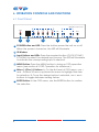
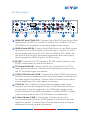
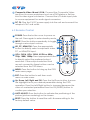
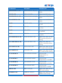
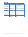
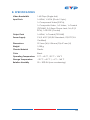
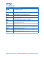
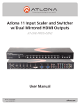
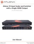
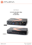
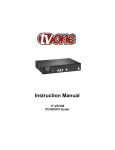
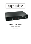
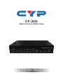
CP-255I Multi-Format to HDMI Scaler Operation Manual DISCLAIMERS The information in this manual has been carefully checked and is believed to be accurate. Cypress Technology assumes no responsibility for any infringements of patents or other rights of third parties which may result from its use. Cypress Technology assumes no responsibility for any inaccuracies that may be contained in this document. Cypress also makes no commitment to update or to keep current the information contained in this document. Cypress Technology reserves the right to make improvements to this document and/or product at any time and without notice. COPYRIGHT NOTICE No part of this document may be reproduced, transmitted, transcribed, stored in a retrieval system, or any of its part translated into any language or computer file, in any form or by any means— electronic, mechanical, magnetic, optical, chemical, manual, or otherwise—without express written permission and consent from Cypress Technology. © Copyright 2011 by Cypress Technology. All Rights Reserved. Version 1.1 August 2011 TRADEMARK ACKNOWLEDGMENTS All products or service names mentioned in this document may be trademarks of the companies with which they are associated. SAFETY PRECAUTIONS Please read all instructions before attempting to unpack, install or operate this equipment and before connecting the power supply. Please keep the following in mind as you unpack and install this equipment: • Always follow basic safety precautions to reduce the risk of fire, electrical shock and injury to persons. • To prevent fire or shock hazard, do not expose the unit to rain, moisture or install this product near water. • Never spill liquid of any kind on or into this product. • Never push an object of any kind into this product through any openings or empty slots in the unit, as you may damage parts inside the unit. • Do not attach the power supply cabling to building surfaces. • Use only the supplied power supply unit (PSU). Do not use the PSU if it is damaged. • Do not allow anything to rest on the power cabling or allow any weight to be placed upon it or any person walk on it. • To protect the unit from overheating, do not block any vents or openings in the unit housing that provide ventilation and allow for sufficient space for air to circulate around the unit. REVISION HISTORY VERSION NO. DATE (DD/MM/YY) SUMMARY OF CHANGE VS1 25/11/11 First release VR2 03/07/13 Input 1080i resolution @60/50 VR3 18/10/13 RS-232 Port CONTENTS 1. Introduction���������������������������������������������� 1 2. Applications��������������������������������������������� 1 3. Package Contents���������������������������������� 1 4. System Requirements������������������������������ 1 5. Features���������������������������������������������������� 2 6. Operation Controls and Functions��������� 3 6.1 Front Panel�������������������������������������������3 6.2 Rear Panel�������������������������������������������4 6.3 Remote Control�����������������������������������5 6.4 OSD Menu��������������������������������������������6 6.5 RS-232 Pin Assignment������������������������7 6.6 RS-232 Setting Commands�����������������8 6.7 RS-232 Status Commands����������������12 6.8 Resolution Supports���������������������������14 8. Specifications���������������������������������������� 16 9. Acronyms����������������������������������������������� 17 1. INTRODUCTION The Multi-Format to HDMI Scaler is designed to upscale digital/analog video signals from Composite, S-Video, PC, Component (HD) and HDMI input sources, to digital HDMI output of a wide range of HDTV and PC resolutions including 1080p and WUXGA (1920 x 1200). As well as upscaling video, the scaler box also converts digital/analog audio signals to digital format, which can then be output either through HDMI combined with the video signal or separately via the discrete Coaxial S/PDIF output. The Scaler has a comprehensive on-screen display (OSD) menu that allows the user to select a variety of output resolutions and adjust them for the best picture quality. 2. APPLICATIONS • Upscale the video from standard definition sources or a PC/Laptop to a HDMI equipped display. 3. PACKAGE CONTENTS • Multi-Format to HDMI Scaler • Remote Control • 1×D-Sub 15-pin Cable • 1×Composite Video Cable (3 RCA) • 5 V/3 A DC Power Supply Adaptor • Operation Manual 4. SYSTEM REQUIREMENTS • INPUT: Composite, Component, S-Video or HDMI, or PC VGA video/ audio source. • OUTPUT: HDMI equipped TV or monitor, optional Coaxial (S/PDIF) equipped receiver/amplifier. 1 5. FEATURES • HDMI, HDCP 1.1 and DVI 1.0 compliant • Scales any PC (VGA~WUXGA) or HD (480i~1080p) resolutions to from another PC/HD resolutions • Automatically detects the correct settings of the connected display and outputs the corresponding resolution and refresh rate, when the NATIVE output is selected • Supports 50/60 Hz frame rate conversion • Supports 3D motion video adaptive, 3D de-interlacing, and 3:2 / 2:2 pull-down detection and recovery • Provides output picture adjustment on contrast, brightness, hue, saturation, sharpness, RGB (color tone) level, and aspect ratio size • Supports high resolution input/output: PC: VGA, SVGA, XGA, SXGA, UXGA, WXGA, WSXGA, and WUXGA HDTV: 480i, 576i, 480p, 576p, 720p, 1080i and 1080p • Supports digital and analog audio input and digital output 2 6. OPERATION CONTROLS AND FUNCTIONS 6.1 Front Panel Digital Video Scaler Processor POWER CV SV COMP PC HDMI MENU 1 2 3 4 - + 5 ENTER 6 1 POWER Button and LED: Press the button power the unit on or off. When the power is turned on, the LED will illuminate. 2 IR Window 3 Input Buttons and LEDs: Press the required button (CV/SV/COMP/ PC/HDMI) to select the desired input source. The LED will illuminate to indicate the corresponding input is selected. 4 MENU Button: Press the MENU button to bring up OSD operation menu (see section 6.3 OSD Operation for reference.) 5 Minus (-)/Plus (+) Buttons: A. On the first level of OSD menu, use + and − buttons to move up/down the menu to highlight the item for selection. B. Once the desired option is selected, use + and − buttons to toggle between setting values. 6 ENTER Button: In the OSD menu, use the ENTER button to confirm the selection. 3 6.2 Rear Panel 3 CO-AX OUT AUX IN 6 RS-232 PC IN R L CO-AX 8 R CV L DC 5V PC IN HDMI OUT HDMI IN Cr/Pr 1 2 4 Cb/Pb 5 Y R L SV 7 9 1 HDMI OUT and COAX OUT: Connect the HDMI OUT port to an HDMI display such as HDTV or monitor. Connect the COAXIAL OUT port (TOSLINK) to an amplifier for separate digital audio output. 2 HDMI IN and AUX IN: Connect the HDMI IN port to an HDMI source device such as a DVD player or set-top box or connect to a DVI source equipment such as a PC with an HDMI to DVI cable. Use the AUX IN port to input the audio signal when the video signal input through the HDMI IN port is an DVI source. 3 RS-232: Connect to a PC/Laptop or RS-232 control system to use RS-232 commands to control the device. 4 PC IN and Audio IN: Connect the D-sub 15-pin port to a PC for video signal conversion. Connect the 3.5mm phone jack port to the PC for audio signal conversion. 5 YCbCr/YPbPr IN and L/R IN: Connect the YCbCr/YPbPr input ports (3 RCA) to source equipment such as a DVD player or set-top box for video signal conversion. Connect the L/R audio input ports to source equipment for audio signal conversion. 6 COAX IN: The COAXIAL port provides the digital audio input support, and can be assigned to any of the video inputs. Once connected, it can be assigned in the OSD Menu under Audio Source Selection by selecting between Coaxial (S/PDIF) or other audio source (see section '6.4 OSD Menu' for reference). 7 S-Video IN and L/R IN: Connect the S-Video input port to source equipment such as a DVD player or set-top box for vido signal conversion. Connect the L/R audio input ports to source equipment for audio signal conversion. 4 8 Composite Video IN and L/R IN: Connect the Composite Video input port to source equipment such as a DVD player or Set-top box for video signal conversion. Connect the L/R audio input ports to source equipment for audio signal conversion. 9 DC 5V: Plug the 5 V DC power supply into the unit and connect the adaptor to AC wall outlet. 6.3 Remote Control 1 POWER: Press the button once to power on the unit. Press again to enter standby mode. 2 2 INPUT: Press the button repeatedly to toggle 3 1 through various input sources. 3 HD, PC, HDMI/DVI: Press the appropriate button to directly select component video, PC, or HDMI/DVI input. 4 4 VGA, SVGA, XGA, SXGA, UXGA or 480p, 6 720p, 1080i, 1080p: Press appropriate button to directly select the preferred output resolution. Other output resolutions that 9 are not covered by these buttons can be selected from the OSD Menu. 5 MENU: Press the button to bring up the OSD main menu page. 6 EXIT: Press the button to exit from a sub menu or main menu. 7 Up, Down, Left, Right and OK: Press the Up/Down button to move the highlight bar to your desired parameter during the OSD operation. Press the Left/Right button to increase/decrease the value of a selected parameter.Press the OK (ENTER) button to confirm your selection. 8 AUTO ADJUST: Press the button to optimize the positioning of the picture (picture centering) on the screen. 9 RESET: Press the button to reset the unit's firmware setting to the factory default value. 5 5 7 8 6.4 OSD Menu MAIN MENU SUBMENU ADJUSTMNET VIDEO PICTURE MODE USER, STANDARD, VIVID, MOVIE CONTRAST 0~100 (50) BRIGHTNESS 0~100 (45) HUE 0~100 (50) SATURATION 0~100 (60) SHARPNESS 0~100 (32) SCALE OVERSCAN, UNDERSCAN, LETTERBOX, PANSCAN, FULL COLOR OUTPUT NR LOW, MIDDLE, HIGH, OFF EXIT - COLOR TONE USER, NORMAL, WARM, COOL RED 0~100 (47) GREEN 0~100 (47) BLUE 0~100 (47) EXIT - - NATIVE, VGA, SVGA, XGA, SXGA, UXGA, 480I, 480P, 720P@60 HZ, 1080I@30 HZ, 1080P@60 HZ, 576I, 576P, 720P@50 HZ, 1080I@25 HZ, 1080P@50HZ, WXGA, WSXGA, WUXGA OSD HPOSITION 0~100 (50) VPOSITION 0~100 (50) TIMER (SEC) 0~100 (10) TRANSP 0~8 (5) EXIT - 6 MAIN MENU SUBMENU ADJUSTMNET AUDIO SOURCE HDMI, L/R, COAXIAL DELAY OFF, 40ms, 110ms, 150ms SOUND ON, MUTE EXIT - - SOURCE (Input interface) INFORMATION INPUT (Input resolution) OUTPUT (Output resolution) VERSION (Firmware version) EXIT - - Note: Items in brackets are the default values for those settings. 6.5 RS-232 Pin Assignment HDMI SCALER PIN ASSIGNMENT PIN ASSIGNMENT 1 NC 1 NC 2 TXD 2 RXD 3 RXD 3 TXD 4 NC 4 NC 5 GND 5 GND 6 NC 6 NC 7 NC 7 NC 8 NC 8 NC 9 NC 9 NC Baud Rate: 19200 bps Data Bit: 8-bits Parity: None Stop Bit: 1-bit 7 REMOTE CONTROL 6.6 RS-232 Setting Commands COMMAND RESPONSE DESCRIPTION S POWER 0 POWER OFF Power OFF the unit S POWER 1 POWER ON Power ON the unit S SOURCE 0 SOURCE CV Set the source to the Composite Video input S SOURCE 1 SOURCE SV Set the source to the S-Video input S SOURCE 2 SOURCE COMP Set the source Component Video input S SOURCE 3 SOURCE PC Set the source to the PC input S SOURCE 4 SOURCE HDMI Set the source to the HDMI input S OUTPUT 0 OUTPUT NATIVE Set the output resolution to the display's Native resolution S OUTPUT 1 OUTPUT VGA Set the output resolution to VGA S OUTPUT 2 OUTPUT SVGA Set the output resolution to SVGA S OUTPUT 3 OUTPUT XGA Set the output resolution to XGA S OUTPUT 4 OUTPUT SXGA Set the output resolution to SXGA S OUTPUT 5 OUTPUT UXGA Set the output resolution to UXGA S OUTPUT 6 OUTPUT 480I Set the output resolution to 480i S OUTPUT 7 OUTPUT 480P Set the output resolution to 480p S OUTPUT 8 OUTPUT 720P Set the output resolution to 720p@60 Hz S OUTPUT 9 OUTPUT 1080I Set the output resolution to 1080i@60 Hz S OUTPUT 10 OUTPUT 1080P Set the output resolution to 1080p@60 Hz 8 COMMAND RESPONSE DESCRIPTION S OUTPUT 11 OUTPUT 576I Set the output resolution to 576i@60 Hz S OUTPUT 12 OUTPUT 576P Set the output resolution to 576p@60 Hz S OUTPUT 13 OUTPUT 720P Set the output resolution to 720p@50 Hz S OUTPUT 14 OUTPUT 1080I50 Set the output resolution to 1080i@50 Hz S OUTPUT 15 OUTPUT 1080P50 Set the output resolution to 1080p@50 Hz S OUTPUT 16 OUTPUT WXGA Set the output resolution to WXGA resolution S OUTPUT 17 OUTPUT WSXGA Set the output resolution to WSXGA S OUTPUT 18 OUTPUT WUXGA Set the output resolution to WUXGA S SIZE 0 SIZE FULL Set the output size to FULL S SIZE 1 SIZE OVERSCAN Set the output size to OVERSCAN S SIZE 2 SIZE UNDERSCAN Set the output size to UNDERSCAN S SIZE 3 SIZE LETTERBOX Set the output size to LETTERBOX S SIZE 4 SIZE PANSCAN Set the output size to PANSCAN S PICTUREMODE 0 PICTUREMODE STANDARD Set the picture mode to STANDARD S PICTUREMODE 1 PICTUREMODE MOVIE Set the picture mode to MOVIE S PICTUREMODE 2 PICTUREMODE VIVID Set the picture mode to VIVID S PICTUREMODE 3 PICTUREMODE USER Set the picture mode to USER S CONTRAST 0~100 CONTRAST 0~100 (50) Adjust the CONTRAST value 9 COMMAND RESPONSE DESCRIPTION S BRIGHTNESS 0~100 BRIGHTNESS 0~100 (45) Adjust the BRIGHTNESS value S HUE 0~100 HUE 0~100 (50) Adjust the HUE value S SATURATION 0~100 SATURATION 0~100 (60) Adjust the SATURATION value S SHARPNESS 0~100 SHARPNESS 0~100 (32) Adjust the SHARPNESS value S NR 0 NR OFF~HIGH Set the noise reduction to OFF S NR 1 NR LOW Set the noise reduction to LOW S NR 2 NR MIDDLE Set the noise reduction to MIDDLE S NR 3 NR HIGH Set the noise reduction to HIGH S PCHPOSITION 0~100 PCHPOSITION 0~100 Adjust the value for the PC horizontal position setting S PCVPOSITION 0~100 PCVPOSITION 0~100 Adjust the value for the PC vertical position setting S PCCLOCK 0~100 PCCLOCK 0~100 Adjust the value for the PC mode clock setting S PCPHASE 0~63 PCPHASE 0~63 Adjust the value for the PC mode phase setting S COLORTEMP 0 COLORTEMP NORMAL Set the color temperature to NORMAL S COLORTEMP 1 COLORTEMP WARM Set the color temperature to WARM S COLORTEMP 2 COLORTEMP COOL Set the color temperature to COOL S COLORTEMP 3 COLORTEMP USER Set the color temperature to USER S RED 0~100 RED 0~100 (47) Adjust the value for the RED color setting S GREEN 0~100 GREEN 0~100 (47) Adjust the value for the GREEN color setting 10 COMMAND RESPONSE DESCRIPTION S BLUE 0~100 BLUE 0~100 (47) Adjust the value for the BLUE color setting S OSDHPOSITION 0~100 OSDHPOSITION 0~100 (50) Set the value to adjust the horizontal position of the OSD menu S OSDVPOSITION 0~100 OSDVPOSITION 0~100 (50) Set the value to adjust the vertical position of the OSD menu S OSDTIMEOUT 0~100 OSDTIMEOUT 0~100 (10) Set the value for the OSD menu timeout S OSDBACKGROUND 0~8 OSDBACKGROUND 0~8 (5) Set the value for the OSD menu background S AUDIOMUTE 0 AUDIOMUTE OFF Set the audio mute to OFF S AUDIOMUTE 1 AUDIOMUTE ON Set the audio mute to ON S AUDIODELAY 0 AUDIODELAY OFF Set the AUDIO DELAY to OFF S AUDIODELAY 1 AUDIODELAY 40MS Set the AUDIO DELAY to 40ms S AUDIODELAY 2 AUDIODELAY 110MS Set the AUDIO DELAY to 110ms S AUDIODELAY 3 AUDIODELAY 150MS Set the AUDIO DELAY to 150ms S RESET 1 RESET ON System Reset Note: Items in brackets are the default values for those settings. 11 6.7 RS-232 Status Commands COMMAND RESPONSE DESCRIPTION R POWER POWER ON/OFF Reports the current POWER status R SOURCE SOURCE CV~HDMI Report the current SOURCE R OUTPUT OUTPUT NATIVE~WUXGA Reports the current OUTPUT resolution R SIZE SIZE FULL~PANSCAN Reports the current SIZE mode R PICTUREMODE PICTUREMODE STANDARD~USER Reports the picture mode R CONTRAST CONTRAST 0~100 Reports the value (1~100) of the CONTRAST setting R BRIGHTNESS BRIGHTNESS 0~100 Reports the value (1~100) of the BRIGHTNESS setting R HUE HUE 0~100 Reports the value (1~100) of the HUE setting R SATURATION SATURATION 0~100 Reports the value (1~100) of the SATURATION setting R SHARPNESS SHARPNESS 0~100 Reports the value (1~100) of the SHARPNESS setting R NR NR OFF~HIGH Reports the status of the NOISE REDUCTION setting R PCHPOSITION PCHPOSITION 0~100 Reports the value (1~100) of the PC horizantal position setting R PCVPOSITION PCVPOSITION 0~100 Reports the value (1~100) of the PC vertical position setting R PCCLOCK PCCLOCK 0~100 Reports the value (1~100) of the PC CLOCK setting R PCPHASE PCPHASE 0~63 Reports the value (1~63) of the PC PHASE setting R COLORTEMP COLORTEMP NORMAL~USER Reports the current color temperature setting R RED RED 0~100 Reports the value (1~100) of the RED color setting R GREEN GREEN 0~100 Reports the value (1~100) of the GREEN color setting 12 COMMAND RESPONSE DESCRIPTION R BLUE BLUE 0~100 Reports the value (1~100) of the RED color setting R OSDHPOSITION OSDHPOSITION 0~100 Reports the value (1~100) of the OSD MENU horizontal position setting R OSDVPOSITION OSDVPOSITION 0~100 Reports the value (1~100) of the OSD MENU horizontal position setting R OSDTIMEOUT OSDTIMEOUT 0~100 Reports the value (1~100) of the OSD MENU TIMEOUT setting R OSDBACKGROUND OSDBACKGROUND 0~8 Reports the value (1~8) of the OSD MENU BACKGROUND setting R AUDIOMUTE AUDIOMUTE OFF~ON Reports the current AUDIOMUTE status R AUDIODELAY AUDIODELAY OFF~150ms Reports the current AUDIO DELAY status 13 6.8 Resolution Supports HDMI/DVI 480i/576i - * 480i/576i * 480p/576p 480p/576p 720p@50/60 Hz 720p@50/60 Hz 1080i@50/60 Hz - 1080i@25/30 Hz 1080p@50/60 Hz 1080p@50/60 Hz VGA@60/72/75/85 Hz - VGA@60/72/75/85 Hz SVGA@56/60/72/75/85 Hz - SVGA@56/60/72/75/85 Hz XGA@60/70/75/85 Hz - XGA@60/70/75/85 Hz SXGA@60/72/75/85 Hz - SXGA@60/72/75//85 Hz UXGA@60 Hz - UXGA@60 Hz - - - RESOLUTION WXGA@60 Hz (1280×800) WSXGA@60 Hz (1650×1050) WXGA@60 Hz (1920×1200) *480i@30×2/576i@30×2 RESOLUTION WXGA@60 Hz (1280×800) WSXGA@60 Hz (1650×1050) WXGA@60 Hz (1920×1200) HDMI/DVI VGA OUTPUT Component Video INPUT *480i@30×2/576i@30×2 14 7. CONNECTION DIAGRAM Composite Video, Coaxial Digital Audio and Analog Stereo Audio Input RS-232 Control from PC/Laptop or RS-232 Control System RS-232 DVD player DP.BY!PVU BVY!JO ST.343 QD!JO S M DP.BY S M DW ED!6W QD!JO IENJ!PVU IENJ!JO Ds0Qs Dc0Qc Z S M TW Coaxial Digital Audio Output AV Receiver Component Video and Analog Stereo Audio Input DVD player S-Video and Analog Stereo Audio Input Blu-ray player HDMI Output HDMI Input (with Optional Analog Stereo Audio Input) Set-top Box VGA and Analog Stereo Audio Input HDTV 15 Laptop 8. SPECIFICATIONS Video Bandwidth 1.65 Gbps (Single-link) Input Ports 1×HDMI, 1×VGA (D-sub 15-pin), 1×Component Video(3 RCA), 1×Composite Video, 1×S-Video, 1×Coaxial (TSOLINK), 2×3.5mm Phone Jack, 3×L/R (2 RCA), 1×RS-232 (Control) Output Ports 1×HDMI, 1×Coaxial (TSOLINK) Power Supply 5 V/3 A DC (US/EU Standards, CE/FCC/UL Certified) Dimensions 215 mm (W)×154 mm (D)×47 mm (H) Weight 1,000 g Chassis Material Plastic Color Black Operating Temperature 0 ˚C ~ 40 ˚C / 32 ˚F ~ 104 ˚F Storage Temperature −20 ˚C ~ 60 ˚C / −4 ˚F ~ 140 ˚F Relative Humidity 20 ~ 90% RH (non-condensing) 16 9. ACRONYMS ACRONYM COMPLETE TERM COMP Component Video CV Composite Video DVI Digital Visual Interface HDMI High-Definition Multimedia Interface IR Infrared NR Noise Reduction NTSC National Television System Committee OSD On-screen Display (Menu) PAL Phase Alternating Line SV S-Video TOSLINK Toshiba Link UXGA Ultra Extended Graphics Array VGA Video Graphics Array XGA Video Graphics Array WUXGA Wide Ultra Extended Graphics Array 17 CYPRESS TECHNOLOGY CO., LTD Home page: http://www.cypress.com.tw