1
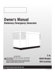
Owner's Manual
Stationary Emergency Generator
NOT INTENDED FOR USE IN CRITICAL LIFE SUPPORT
APPLICATIONS.
ONLY QUALIFIED ELECTRICIANS OR CONTRACTORS
SHOULD ATTEMPT INSTALLATION!
DEADLY EXHAUST FUMES! OUTDOOR INSTALLATION
ONLY!
2.4L
35kW Models
EPA Certified
This manual should remain with the unit.
Cover202 Rev. B 03/11
Part No. 0J2966
Table of Contents
Alarm and Warning Messages..........................................................8-4
Low Oil Pressure Shutdown Alarm ...............................................8-4
High Coolant Temperature Shutdown Alarm ..................................8-4
Overcrank Shutdown Alarm ..........................................................8-4
Overspeed Shutdown Alarm .........................................................8-4
RPM Sensor Failure Shutdown Alarm ...........................................8-4
Under-frequency Shutdown Alarm ................................................8-5
Low Battery Alarm .......................................................................8-5
Low Battery Warning....................................................................8-5
Low Coolant Level Alarm .............................................................8-5
Missing Cam Pulse Alarm ............................................................8-5
Missing Crank Pulse Alarm ..........................................................8-5
Low Fuel Pressure Warning ..........................................................8-5
Governor Sensor Fault Alarm........................................................8-5
Wiring Error Alarm .......................................................................8-5
Undervoltage Alarm .....................................................................8-5
Overvoltage Alarm .......................................................................8-6
Internal Failure Shutdown Alarm ...................................................8-6
Canbus Alarm ..............................................................................8-6
Ignition Alarm ..............................................................................8-6
Maintenance Warning...................................................................8-6
Alarm Cancel ...............................................................................8-6
Common Alarm Relay ......................................................................8-6
Maintenance Alerts ..........................................................................8-6
Menu System...................................................................................8-7
OPERATION .................................................................. 9-1
Stationary Emergency Generator Control and Operation ....................9-1
Operating Unit with Manual Transfer Switch......................................9-1
Engine Start-up and Transfer ........................................................9-1
Retransfer and Shutdown .............................................................9-1
Operating Unit with Automatic Transfer Switch .................................9-1
MAINTENANCE........................................................... 10-1
General Maintenance......................................................................10-1
Check Engine Oil ........................................................................10-1
Changing Engine Oil ...................................................................10-1
Cooling Intake/Outlet ..................................................................10-1
Inspect Cooling System .............................................................10-1
Engine Coolant ...........................................................................10-2
Coolant Change .........................................................................10-2
Overload Protection for Engine DC Electrical System ..................10-2
Exercise System ........................................................................10-2
Perform Visual Inspection ..........................................................10-2
Inspect Exhaust System .............................................................10-2
Check Fan Belt ...........................................................................10-2
Inspect Engine Governor ............................................................10-2
Changing the Engine Air Filter .....................................................10-2
Spark Plugs ...............................................................................10-3
Battery Maintenance ..................................................................10-3
Battery Replacement ..................................................................10-3
Battery Fluid...............................................................................10-3
Cleaning the Stationary Emergency Generator ............................10-3
SERVICE SCHEDULE ................................................. 11-1
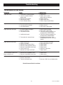
TROUBLESHOOTING ................................................. 12-1
Troubleshooting Guide....................................................................12-1
EMISSIONS WARRANTY............................................ 13-1
NOTES
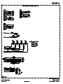
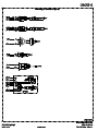
EXPLODED VIEWS & PARTS LISTS
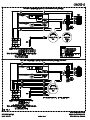
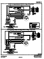
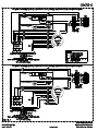
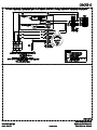
WIRING DIAGRAMS & SCHEMATICS
Content048 Rev. A 05/10
SECTION
PAGE
INTRODUCTION ........................................................... 1-1
Read this Manual Thoroughly .......................................................1-1
Operation and Maintenance ..........................................................1-1
How to Obtain Service .................................................................1-1
SAFETY RULES ............................................................ 1-2
GENERAL INFORMATION ............................................ 2-1
Identification Record ........................................................................2-1
Data Label ...................................................................................2-1
EQUIPMENT DESCRIPTION ........................................ 3-1
Equipment Description .....................................................................3-1
Engine Oil Recommendations ...........................................................3-1
Coolant Recommendations ..............................................................3-1
ENGINE PROTECTIVE DEVICES ................................. 4-1
Engine Protective Devices ................................................................4-1
High Coolant Temperature Sender ................................................4-1
Low Coolant Level Sensor............................................................4-1
Low Oil Pressure Switch ..............................................................4-1
Overcrank Shutdown ....................................................................4-1
Overspeed Shutdown ...................................................................4-1
RPM Sensor Loss Shutdown........................................................4-1
DC Fuses .....................................................................................4-1
FUEL SYSTEM .............................................................. 5-1
Fuel Requirements .......................................................................5-1
Natural Gas Fuel System ..............................................................5-1
Propane Vapor Withdrawal Fuel System........................................5-1
LP Liquid Fuel System..................................................................5-1
SPECIFICATIONS ......................................................... 6-1
Stationary Emergency Generator ..................................................6-1
Engine .........................................................................................6-1
Cooling System............................................................................6-1
Fuel System .................................................................................6-1
Electrical System .........................................................................6-1
Weather and Maintenance Kits .....................................................6-2
Reconfiguring the Fuel System .........................................................6-2
Fuel System .................................................................................6-2
Control Panel ...............................................................................6-2
GENERAL INFORMATION ............................................ 7-1
Alternator AC Lead Connections .......................................................7-1
Four-lead, Single-phase Stator......................................................7-1
Alternator Power Winding Connections .............................................7-1
3-phase Alternators ("Y" Configuration) ........................................7-1
3-phase Alternators ("Delta" Configuration)...................................7-2
CONTROL PANEL ......................................................... 8-1
Control Panel Interface .....................................................................8-1
Using the Auto/Off/Manual Switch ................................................8-1
Activate the Generator ......................................................................8-1
Display Interface Menus...................................................................8-1
Activation Chart ...........................................................................8-2
Setting the Exercise Timer ................................................................8-3
Low Speed Exercise .....................................................................8-3
User Adjustable Settings ..................................................................8-3
Fuel Conversion ...............................................................................8-3
Operation .........................................................................................8-3
Automatic Transfer Operation .......................................................8-3
Sequence of Automatic Operation ................................................8-4
Crank Cycles and Overcrank Shutdown ........................................8-4
Auto Start ........................................................................................8-4
Manual Start ....................................................................................8-4
Safety Instructions
THESE INSTRUCTIONS – The manufacturer suggests that these rules for safe operation be copied and posted in potential
nSAVE
hazard areas. Safety should be stressed to all operators, potential operators, and service and repair technicians for this
equipment.
INTRODUCTION
This symbol points out potential electrical shock hazard.
This symbol points out potential fire hazard.
Thank you for purchasing this model of the stationary emergency
generator product line.
Every effort was expended to make sure that the information and
instructions in this manual were both accurate and current at the
time the manual was written. However, the manufacturer reserves
the right to change, alter or otherwise improve this product(s) at
any time without prior notice.
The operator is responsible for proper and safe use of the equipment. The manufacturer strongly recommends that the operator
read this Owner's Manual and thoroughly understand all instructions before using this equipment. The manufacturer also strongly
recommends instructing other users to properly start and operate
the unit. This prepares them if they need to operate the equipment
in an emergency.
READ THIS MANUAL THOROUGHLY
If any portion of this manual is not understood, contact the nearest
Service Dealer for starting, operating and servicing procedures.
For safety reasons, the manufacturer recommends that this
equipment be installed, serviced and repaired by a Service
Dealer or other competent, qualified electrician or installation
technician who is familiar with applicable codes, standards and
regulations. The operator also must comply with all such codes,
standards and regulations.
Throughout this publication, and on tags and decals affixed to the
generator, DANGER, WARNING, CAUTION and NOTE blocks are
used to alert personnel to special instructions about a particular
service or operation that may be hazardous if performed incorrectly or carelessly. Observe them carefully. Their definitions are
as follows:
OPERATION AND MAINTENANCE
It is the operator's responsibility to perform all safety checks, to
make sure that all maintenance for safe operation is performed
promptly, and to have the equipment checked periodically by a
Service Dealer. Normal maintenance service and replacement of
parts are the responsibility of the owner/operator and, as such,
are not considered defects in materials or workmanship within the
terms of the warranty. Individual operating habits and usage contribute to the need for maintenance service.
INDICATES A HAZARDOUS SITUATION OR ACTION WHICH, IF
NOT AVOIDED, WILL RESULT IN DEATH OR SERIOUS INJURY.
Indicates a hazardous situation or action which, if not
avoided, could result in death or serious injury.
Proper maintenance and care of the generator ensure a minimum
number of problems and keep operating expenses at a minimum.
See a Service Dealer for service aids and accessories.
Indicates a hazardous situation or action which, if not
avoided, could result in minor or moderate injury.
NOTE:
Operating instructions presented in this manual assume that the
generator electric system has been installed by a Service Dealer or
other competent, qualified contractor. Installation of this equipment
is not a “do-it-yourself” project.
Notes contain additional information important to a procedure
and will be found within the regular text body of this manual.
These safety warnings cannot eliminate the hazards that they
indicate. Common sense and strict compliance with the special
instructions while performing the service are essential to preventing accidents.
HOW TO OBTAIN SERVICE
When the generator requires servicing or repairs, simply contact
a Service Dealer for assistance. Service technicians are factorytrained and are capable of handling all service needs.
Four commonly used safety symbols accompany the DANGER,
WARNING and CAUTION blocks. The type of information each
indicates is as follows:
When contacting a dealer about parts and service, always supply
the complete Model Number, Serial Number and Type Code (where
applicable) from the DATA LABEL that is affixed to the unit.
This symbol points out important safety information that,
if not followed, could endanger personal safety and/or
property of others.
n
This symbol points out potential explosion hazard.
Safety004 Rev. F 05/10
1-1
Safety Instructions
SAFETY RULES
• The engine exhaust fumes contain carbon monoxide gas, which
can be DEADLY. This dangerous gas, if breathed in sufficient
concentrations, can cause unconsciousness or even death. For
that reason, adequate ventilation must be provided. This should
be considered prior to installing the generator. The unit should
be positioned to direct exhaust gasses safely away from any
building where people, animals, etc., will not be harmed. Any
exhaust stacks that ship loose with the unit must be installed
properly per the manufacturer's instruction, and in strict compliance with applicable codes and standards.
• Keep hands, feet, clothing, etc., away from drive belts, fans,
and other moving or hot parts. Never remove any drive belt or
fan guard while the unit is operating.
• Adequate, unobstructed flow of cooling and ventilating air is
critical in any room or building housing the generator to prevent
buildup of explosive gases and to ensure correct generator
operation. Do not alter the installation or permit even partial
blockage of ventilation provisions, as this can seriously affect
safe operation of the generator.
• Keep the area around the generator clean and uncluttered.
Remove any materials that could become hazardous.
• When working on this equipment, remain alert at all times.
Never work on the equipment when physically or mentally
fatigued.
• Inspect the generator regularly, and promptly repair or replace
all worn, damaged or defective parts using only factoryapproved parts.
• Before performing any maintenance on the generator, disconnect its battery cables to prevent accidental start-up. Disconnect
the cable from the battery post indicated by a NEGATIVE, NEG
or (–) first. Reconnect that cable last.
• Never use the generator or any of its parts as a step. Stepping
on the unit can stress and break parts, and may result in dangerous operating conditions from leaking exhaust gases, fuel
leakage, oil leakage, etc.
Study these SAFETY RULES carefully before installing, operating
or servicing this equipment. Become familiar with this Owner’s
Manual and with the unit. The generator can operate safely, efficiently and reliably only if it is properly installed, operated and
maintained. Many accidents are caused by failing to follow simple
and fundamental rules or precautions.
The manufacturer cannot anticipate every possible circumstance
that might involve a hazard. The warnings in this manual, and on
tags and decals affixed to the unit are, therefore, not all inclusive.
If a procedure, work method or operating technique is used that
the manufacturer does not specifically recommend, ensure that it
is safe for others. Also make sure the procedure, work method or
operating technique utilized does not render the generator unsafe.
the safe design of this generator,
nDespite
operating this equipment imprudently, neglecting its maintenance or being careless can cause
possible injury or death. Permit only responsible and capable persons to install, operate or
maintain this equipment.
these machines. Ensure all steps are taken to
Potentially lethal voltages are generated by
render the machine safe before attempting to
work on the generator.
of the generator are rotating and/or hot
nParts
during operation. Exercise care near running
generators.
GENERAL HAZARDS
• For safety reasons, the manufacturer recommends that this
equipment be installed, serviced and repaired by a Service
Dealer or other competent, qualified electrician or installation
technician who is familiar with applicable codes, standards
and regulations. The operator also must comply with all such
codes, standards and regulations.
• Installation, operation, servicing and repair of this (and related)
equipment must always comply with applicable codes, standards, laws and regulations. Adhere strictly to local, state and
national electrical and building codes. Comply with regulations
the Occupational Safety and Health Administration (OSHA) has
established. Also, ensure that the generator is installed, operated and serviced in accordance with the manufacturer’s instructions and recommendations. Following installation, do nothing
that might render the unit unsafe or in noncompliance with the
aforementioned codes, standards, laws and regulations.
ELECTRICAL HAZARDS
• All stationary emergency generators covered by this manual
produce dangerous electrical voltages and can cause fatal
electrical shock. Utility power delivers extremely high and dangerous voltages to the transfer switch as well as the generator.
Avoid contact with bare wires, terminals, connections, etc.,
on the generator as well as the transfer switch, if applicable.
Ensure all appropriate covers, guards and barriers are in place
before operating the generator. If work must be done around
an operating unit, stand on an insulated, dry surface to reduce
shock hazard.
• Do not handle any kind of electrical device while standing in water, while barefoot, or while hands or feet are wet.
DANGEROUS ELECTRICAL SHOCK MAY RESULT.
1-2
Safety004 Rev. F 05/10
Safety Instructions
FIRE HAZARDS
• If personnel must stand on metal or concrete while installing,
operating, servicing, adjusting or repairing this equipment,
place insulative mats over a dry wooden platform. Work on the
equipment only while standing on such insulative mats.
• The National Electrical Code (NEC) requires the frame and
external electrically conductive parts of the generator to be connected to an approved earth ground. This grounding will help
prevent dangerous electrical shock that might be caused by a
ground fault condition in the generator or by static electricity.
Never disconnect the ground wire.
• Wire gauge sizes of electrical wiring, cables and cord sets must
be adequate to handle the maximum electrical current (ampacity) to which they will be subjected.
• Before installing or servicing this (and related) equipment, make
sure that all power voltage supplies are positively turned off at
their source. Failure to do so will result in hazardous and possibly fatal electrical shock.
• Connecting this unit to an electrical system normally supplied
by an electric utility shall be by means of a transfer switch so as
to isolate the generator electric system from the electric utility
distribution system when the generator is operating. Failure to
isolate the two electric system power sources from each other
by such means will result in damage to the generator and may
also result in injury or death to utility power workers due to
backfeed of electrical energy.
• Stationary emergency generators installed with an automatic
transfer switch will crank and start automatically when normal
(utility) source voltage is removed or is below an acceptable
preset level. To prevent such automatic start-up and possible
injury to personnel, disable the generator’s automatic start circuit (battery cables, etc.) before working on or around the unit.
Then, place a “Do Not Operate” tag on the generator control
panel and on the transfer switch.
• In case of accident caused by electric shock, immediately
shut down the source of electrical power. If this is not possible, attempt to free the victim from the live conductor. AVOID
DIRECT CONTACT WITH THE VICTIM. Use a nonconducting
implement, such as a dry rope or board, to free the victim from
the live conductor. If the victim is unconscious, apply first aid
and get immediate medical help.
• Never wear jewelry when working on this equipment. Jewelry
can conduct electricity resulting in electric shock, or may get
caught in moving components causing injury.
• Keep a fire extinguisher near the generator at all times. Do NOT
use any carbon tetra-chloride type extinguisher. Its fumes are
toxic, and the liquid can deteriorate wiring insulation. Keep the
extinguisher properly charged and be familiar with its use. If
there are any questions pertaining to fire extinguishers, consult
the local fire department.
EXPLOSION HAZARDS
• Properly ventilate any room or building housing the generator to
prevent build-up of explosive gas.
• Do not smoke around the generator. Wipe up any fuel or oil
spills immediately. Ensure that no combustible materials are left
in the generator compartment, or on or near the generator, as
FIRE or EXPLOSION may result. Keep the area surrounding the
generator clean and free from debris.
• These generators may operate using one of several types
of fuels. All fuel types are potentially FLAMMABLE and/or
EXPLOSIVE and should be handled with care. Comply with all
laws regulating the storage and handling of fuels. Inspect the
unit’s fuel system frequently and correct any leaks immediately.
Fuel supply lines must be properly installed, purged and leak
tested according to applicable fuel-gas codes before placing
this equipment into service.
• Diesel fuels are highly FLAMMABLE. Gaseous fluids such
as natural gas and liquid propane (LP) gas are extremely
EXPLOSIVE. Natural gas is lighter than air, and LP gas is heavier
than air; install leak detectors accordingly.
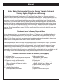
CALIFORNIA PROPOSITION 65 WARNING
Engine exhaust and some of its constituents are known
to the State of California to cause cancer, birth defects
and other reproductive harm.
CALIFORNIA PROPOSITION 65 WARNING
This product contains or emits chemicals known to the
State of California to cause cancer, birth defects and
other reproductive harm.
Safety004 Rev. F 05/10
1-3
General Information
IDENTIFICATION RECORD
NOTE:
For actual information related to this particular model, please
refer to the Manual Drawing Listing located at the end of this
manual, or to the data label affixed to the unit.
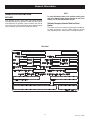
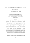
DATA LABEL
Every generator set has a DATA LABEL that contains important
information pertinent to the generator. The data label, which can be
found attached to the generator’s lower connection box, lists the
unit’s serial number and its rated voltage, amps, wattage capacity,
phase, frequency, rpm, power factor, production date, etc.
Stationary Emergency Generator Model and Serial
Number
This number is the key to numerous engineering and manufacturing details pertaining to your unit. Always supply this number
when requesting service, ordering parts or seeking information.
Data Label
Identy005 Rev. D 05/10
2-1
Equipment Description
EQUIPMENT DESCRIPTION
COOLANT RECOMMENDATIONS
This equipment is a revolving field, alternating current Stationary
Emergency Generator. It is powered by a gaseous fueled engine
operating at 1800 rpm for 4-pole direct drive units, 3600 rpm for
2-pole direct drive units and 2300 - 3000 rpm for quiet drive gear
units. See the Specifications section for exact numbers. The unit
comes complete with a sound attenuated enclosure, internally
mounted muffler, control console, mainline circuit breaker, battery charger, and protective alarms as explained in the following
paragraph.
Use a mixture of half low silicate ethylene glycol base anti-freeze
and deionized water. Cooling system capacity is listed in the
specifications. Use only deionized water and only low silicate
anti-freeze. If desired, add a high quality rust inhibitor to the recommended coolant mixture. When adding coolant, always add the
recommended 50-50 mixture.
not use any chromate base rust inhibitor
nDo
with ethylene glycol base anti-freeze or chromium hydroxide (“green slime”) forms and will
All AC connections, including the power leads from the alternator, 120 volt battery charger input and control connections to the
transfer switch are available in the main connection box.
cause overheating. Engines that have been
operated with a chromate base rust inhibitor
must be chemically cleaned before adding ethylene glycol base anti-freeze. Using any high
silicate anti-freeze boosters or additives will
also cause overheating. The manufacturer also
recommends that any soluble oil inhibitor is
NOT used for this equipment.
The Stationary Emergency Generator incorporates the following
alternator features:
• Rotor and Stator insulation class is rated as defined by NEMA
MG1-32.6, NEMA MG1-1.66. The generator is self ventilated
and drip-proof constructed. Refer to the Specifications section
or the data label for the class ratings.
• The voltage waveform deviation, total harmonic content of the
AC waveform and telephone influence factor have been evaluated and are acceptable according to NEMA MG1-32.
not remove the radiator pressure cap while
nDo
the engine is hot or serious burns from boiling
liquid or steam could result.
ENGINE OIL RECOMMENDATIONS
The unit has been filled with 5W-20 engine oil at the factory. Use
a high-quality detergent oil classified “For Service SJ or SH.”
Detergent oils keep the engine cleaner and reduce carbon deposits.
When changing the engine oil, be sure to use 5W-30 engine oil.
glycol base antifreeze is poisonous.
nEthylene
Do not use mouth to siphon coolant from the
radiator, recovery bottle or any container. Wash
hands thoroughly after handling. Never store
used antifreeze in an open container because
animals are attracted to the smell and taste of
antifreeze even though it is poisonous to them.
attempt to crank or start the engine before
nAny
it has been properly serviced with the recommended oil may result in an engine failure.
NOTE:
If not already equipped, it is strongly recommended to use the
optional Cold Weather Start Kit for temperatures below 32° F.
The part number for the Cold Weather Start Kit can be found
in the Specifications section or by contacting an authorized
dealer. The oil grade for temperatures below 32° F is 5W-30
synthetic oil.
Equip001 Rev. G 05/10
3-1
Engine Protective Devices
ENGINE PROTECTIVE DEVICES
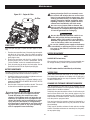
OVERCRANK SHUTDOWN
The Stationary Emergency Generator may be required to operate
for long periods of time without an operator on hand to monitor
such engine conditions as coolant temperature, oil pressure or
rpm. For that reason, the engine has several devices designed to
protect it against potentially damaging conditions by automatically
shutting down the unit when the oil pressure is too low, the coolant
temperature is too high, the coolant level is too low, or the engine
is running too fast.
After a prespecified duration of cranking, this function ends the
cranking if the engine has failed to start. The overcrank message
will turn ON. Turn OFF the AUTO/OFF/MANUAL switch, then turn
switch back to AUTO to reset the generator control board.
NOTE:
If the fault is not corrected, the overcrank feature will continue
to activate.
NOTE:
Approximate Crank Cycle Times
Engine protective switches and sensors are mentioned here for
the reader’s convenience. Also refer to the applicable control
panel manual for additional automatic engine shutdown information.
•
•
•
•
•
•
HIGH COOLANT TEMPERATURE SENDER
An analog coolant temperture sender, located in the engine's
cooling system will cause an engine shutdown if the temperature
should exceed approximately 125° C (257° F). The generator will
automatically restart once the temperature has returned to a safe
operating level.
15 seconds ON
7 seconds OFF
7 seconds ON
7 seconds OFF
Repeat for 45 seconds
Approximately 90 seconds total.
OVERSPEED SHUTDOWN
A speed circuit controls engine cranking, start-up, operation and
shutdown. Engine speed signals are delivered to the circuit board
whenever the unit is running. Should the engine overspeed above
a safe, preset value, the circuit board initiates an automatic engine
shutdown. Contact the nearest Authorized Dealer if this failure
occurs.
LOW COOLANT LEVEL SENSOR
To prevent overheating, the engine has a low coolant level sensor.
If the level of engine coolant drops below the level of the low coolant level sensor, the engine automatically shuts down.
RPM SENSOR LOSS SHUTDOWN
If the speed signal to the control panel is lost, engine shutdown
will occur.
LOW OIL PRESSURE SWITCH
This switch has normally closed contacts that are held open by
engine oil pressure during cranking and operating. Should oil pressure drop below the 8 psi range, switch contacts close, and the
engine shuts down. The unit should not be restarted until oil is
added, and the AUTO/OFF/MANUAL switch must be turned to OFF
and then back to AUTO.
DC FUSES
A fuse (7.5 amp) is located on the control panel. It protects the
panel components from damaging overload. Always remove this
fuse before commencing work on the generator. The unit will not
start or crank if the fuse is blown.
A fuse (25 amp) is located in the engine wire harness adjacent
to the DC alternator. It is used to prevent circuit failure due to DC
alternator falure. It will also protect the system in the event of a
wiring short-dircuit. If this fuse is blown, the generator will not
operate. Replace these fuses with the same size, type, and rating.
EngProt003 Rev. B 05/10
4-1
Fuel System
FUEL SYSTEM
NATURAL GAS FUEL SYSTEM
Natural gas is supplied in its vapor state. In most cases, the gas
distribution company provides piping from the main gas distribution line to the standby generator site. The following information
applies to natural gas fuel systems.
FUEL REQUIREMENTS
The Stationary Emergency Generator may be equipped with one of
the following fuel systems:
• Gas pressure in a building is usually regulated by national, state
and local codes.
• To reduce gas pressure to a safe level before the gas enters a
building, a primary regulator is needed. The natural gas supplier
may or may not supply such a regulator.
• It is the responsibility of the gas supplier to make sure sufficient
gas pressure is available to operate the primary regulator.
• Gas pressure at the inlet to the fuel shutoff solenoid must never
exceed approximately 14 inches water column (0.5 psi).
• Natural gas fuel system
• Propane vapor (LPV) fuel system
Recommended fuels should have a Btu content of at least 1,000
Btu's per cubic foot for natural gas; or at least 2,520 Btu's per
cubic foot for LP gas. Ask the fuel supplier for the Btu content of
the fuel.
NOTE:
The fuel consumption requirements are identified in the
Specifications section of the Owner's Manual. Refer to the
Installation Manual if assistance is required for the sizing of
the pipe diameter for the generator. Any piping used to connect
the generator to the fuel supply should be of adequate size to
achieve the 100% load fuel consumption requirements identified in the Specifications section regardless of actual load.
PROPANE VAPOR WITHDRAWAL FUEL SYSTEM
This type of system utilizes the vapors formed above the liquid
fuel in the supply tank. Approximately 10 to 20 percent of the tank
capacity is needed for fuel expansion from the liquid to the vapor
state. The vapor withdrawal system is generally best suited for
smaller engines that require less fuel. The installer should be aware
of the following:
NOTE:
The recommended fuel pressure is identified in the Specifications
section this manual.
• When ambient temperatures are low and engine fuel consumption is high, the vapor withdrawal system may not function
efficiently.
• Ambient temperatures around the supply tank must be high
enough to sustain adequate vaporization, or the system will not
deliver the needed fuel volume.
• In addition to the cooling effects of ambient air, the vaporization
process itself provides an additional cooling effect.
5-1
FuelSys001 Rev. F 04/11
NOTE:
It is the responsibility of the installer to make sure that only
the correct recommended fuel is supplied to the generator fuel
system. Thereafter, the owner/operator must make certain that
only the proper fuel is supplied.
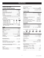
Specifications
SPECIFICATIONS
Engine Lubrication System
Type of Oil Pump ...............................................................Gear
Oil Filter ......................................... Full Flow Spin-on, Cartridge
Crankcase Oil Capacity ...........................................5.25 U.S. qts.
(including filter capacity)
STATIONARY EMERGENCY GENERATOR
Type......................................................................Synchronous
Rotor Insulation..............................................................Class F
Stator Insulation ............................................................Class H
Telephone Interference Factor (TIF) .................................. < 50
Alternator Output Leads 3-phase ..................................... 4-wire
Bearings .................................................................. Sealed Ball
Coupling ................................................................Flexible Disc
Load Capacity (Standby Rating) .....................................35kW*
* NOTE: Generator rating and performance in accordance with ISO8528-5, BS5514, SAE
COOLING SYSTEM
Type............................................. Pressurized Closed Recovery
Water Pump ............................................................. Belt Driven
Fan Speed ..................................................................1500 rpm
Fan Diameter..............................................................22 inches
Fan Mode......................................................................... Puller
Air Flow (inlet air including alternator and
combustion air) ................................................. 2200 ft3/min.
Coolant Capacity ................................................. (2.5 U.S. gal.)
Heat Rejection to Coolant (35kW) .......................145,000 Btu/h
Maximum Operating Air Temp. on Radiator ......... 60° C (150° F)
Maximum Ambient Temperature ......................... 50° C (140° F)
J1349, ISO3046 and DIN 6271 Standards. KW rating is based on LPG fuel and may derate
with natural gas.
Excitation System ............................................................Direct
Generator Output Voltage/kW - 60 Hz kW
Amp
CB Size
120/240V, 1-phase, 1.0 pf
35
146
175
120/208V, 3-phase, 0.8 pf
35
121
150
120/240V, 3-phase, 0.8 pf
35
105
125
277/480V, 3-phase, 0.8 pf
35
53
60
Generator Locked Rotor KVA Available @ Voltage Dip of 35%
Single-phase or 208, 3-phase (35kW) ........................ 59 KVA
480V, 3-phase (35kW) ................................................ 68 KVA
FUEL SYSTEM
Type of Fuel ....................................Natural Gas, Propane Vapor
Carburetor............................................................... Down Draft
Secondary Fuel Regulator............................................ Standard
Fuel Shut-off Solenoid ................................................. Standard
Operating Fuel Pressure ................. 5 in. - 14 in. Water Column
ENGINE
Make ........................................................................... Generac
Model .............................................................................In Line
Cylinders and Arrangement .....................................................4
Displacement ............................................................... 2.4 Liter
Bore.............................................................................. 3.41 in.
Stroke ........................................................................... 3.94 in.
Compression Ratio....................................................... 9.5-to-1
Air Intake System .............................. Turbocharged/Aftercooled
Valve Seats ................................................................ Hardened
Lifter Type.................................................................. Hydraulic
Spark Plug Gap ........................................0.71mm (0.028 inch)
Fuel Consumption - ft3/hr (Natural Gas/LPV)
Exercise
25%
50%
75%
Cycle
Load
Load
Load
35kW 48/19
156/62
282/112
392/156
100%
Load
503/200
ELECTRICAL SYSTEM
Battery Charge Alternator ......................................12V, 30 Amp
Static Battery Charger ..................................................2.5 Amp
Recommended Battery .................................Group 26, 525CCA
System Voltage ............................................................ 12 Volts
Engine Parameters
Rated Synchronous RPM .......................................60 Hz, 1800
Voltage Regulator
Type...........................................................................Electronic
Sensing ................................................................ Single-phase
Regulation........................................................................± 1%
Features ......................................... Adjustable Voltage and Gain
Exhaust System
Exhaust Flow at Rated Output 60 Hz (35kW) ................300 cfm
Exhaust Temp. at Rated Output (35kW) .........................1075° F
Power Adjustment for Ambient Conditions
Temperature Deration
3% for every 10° C above °C (35kW) ..................................25
1.65% for every 10° above °F (35kW) .................................77
Altitude Deration
1% for every 100 m above m (35kW) ...............................915
3% for every 1000 ft. above ft. (35kW)...........................3000
Combustion Air Requirements (Natural Gas)
Flow at rated power, 60 Hz (35kW) ..............................106 cfm
Governor
Type...........................................................................Electronic
Frequency Regulation .............................................Isochronous
Steady State Regulation ..............................................± 0.25%
Controller ................................................................. Nexus
GenSpec093 Rev. B 05/11
6-1
Specifications
WEATHER AND MAINTENANCE KITS
9.
Install the previously removed black pipe onto the outlet
port of the demand regulator. Use pipe sealant on the pipe
threads.
10. Reverse steps 1-4 in this procedure to reactivate the demand
regulator.
11. Follow the instructions in the Control Panel section.
To keep the generator running at its peak, the following kits are
offered:
• Cold Weather Kit
~ Recommended for climates with temperatures below 32° F.
• Scheduled Maintenance Kit
~ Kit includes the recommended parts to maintain the generator. Refer to the Service Schedule for regular maintenance
intervals.
For additional information, or to order any of these kits, please
contact an Authorized Service Dealer or Customer Service
Representative.
injury, including death, or damage
Serious
will occur if not configured properly. Please
consult an Authorized Dealer with any questions.
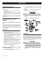
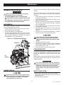
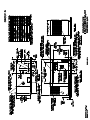
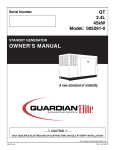
Figure 6.1 — Reconfigure the Fuel System
RECONFIGURING THE FUEL
SYSTEM
NOTE:
All models are configured to run on natural gas from the factory.
Before the generator can be operated using a LP fuel source, the
fuel system and control panel (refer to the installation drawing for
location) must be reconfigured. The steps to reconfigure the generator from a natural gas (NG) to a liquidified petroleum (LP) fuel
source are as follows:
FUEL SYSTEM
1.
2.
3.
4.
5.
6.
7.
Turn the main gas supply off and disconnect the battery.
Remove the carburetor fuel hose from the outlet port of the
demand regulator (see Figure 6.1).
Disconnect the power wires from the fuel solenoid located
on top of the regulator assembly by removing the screw on
the front of the connector and pulling the connector forward,
away from the solenoid body.
Loosen the spring clamp on the small fuel enrichment line and
remove the hose from the hose barb.
Remove the black pipe assembly from the outlet port of the
demand regulator. The solenoid assembly may need to be
removed before performing this operation (Figure 6.1).
Remove the NG fuel jet (loosen counter clockwise) from the
outlet port.
Remove the LP fuel jet (loosen counter clockwise) from the jet
keeper port on the side of the regulator housing. Install this jet
into the outlet port in the regulator casting.
CONTROL PANEL
The FUEL TYPE must be reconfigured in the control panel to finalize the conversion process. This generator is configured at the
factory to operate on natural gas. If conversion to LP is required,
please complete the mechanical conversion process and then call
888-9ACTIVATE for the control panel password. This fuel selection
conversion is required to be password protected by Environmental
Protection Agency [EPA] regulations.
the Generator’s Fuel Regulator is
Whenever
converted from one Fuel type to the other,
the Control Panel must be reconfigured for
the correct fuel type. Failure to convert both
the Regulator and Control Panel will result in
decreased performance and an increase in
emissions, and is a violation of EPA regulations.
NOTE:
The jet sizes are stamped on the individual jets. The larger jet
size is used for running on NG.
8.
Install the previously removed NG jet into the jet keeper port
on the side of the regulator housing.
6-2
GenSpec093 Rev. B 05/11
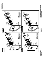
General Information
ALTERNATOR AC LEAD
CONNECTIONS
ALTERNATOR POWER WINDING
CONNECTIONS
The electrical wires in the unit’s AC connection (lower) panel
should be installed according to the number of leads and the
voltage/phase required for the application. The voltage and phase
are described on the generator data label. The number of lead
wires can be identified using the Specifications section and the
power output rating on the generator data label. For example, if
the generator produces 130kW, 277/480 Volt, 3-phase power, the
generator has 12 alternator output leads. Figure 7.3 describes the
stator power winding connection for the generator.
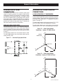
3-PHASE ALTERNATORS ("Y" CONFIGURATION)
The Stationary Emergency Generator is designed to supply
3-phase electrical loads. Electric power is produced in the alternator power windings. These windings were connected at the factory
to the main circuit breaker with a “Y” configuration as shown in
Figures 7.2 through 7.6.
The rated voltage between circuit breaker terminals E1-E2, E1-E3
and E2-E3 is 480V, 208V or 600V depending on the model.
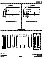
FOUR-LEAD, SINGLE-PHASE STATOR
The rated voltage between each circuit breaker terminal and the
neutral point 00 is 277V, 120V, or 346V depending on the model.
Four-lead alternators (see Figure 7.1) are designed to supply electrical loads with voltage code “A” (240V, 1-phase, 60 Hz). Electrical
power is produced in the stator power windings. These windings
were connected at the factory to the main circuit breaker as shown
in Figure 7.1.
Figure 7.2 — Stator Power Winding
Connections - 3-phase, 277/480V (6 Lead)
E1
The rated voltage between each circuit breaker terminal is 240V.
The rated voltage between each circuit breaker terminal and the
neutral point 00 is 120V.
INTERNAL
CONNECTIONS
S1
Figure 7.1 — Four-lead, Single-phase Stator
L-L
S4
S6
00 (NEUTRAL)
S5
S2
S3
E3
E2
L-N
Figure 7.3 — Stator Power Winding
Connections - 3-phase, 277/480V (12 Lead)
E1
S1
S4
S7
L-L
S6
S9
S10
S11
S8
S5
S2
S3
E3
7-1
L-N
E2
ACConn007 Rev. B 05/10
S12
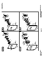
General Information
3-PHASE ALTERNATORS ("DELTA" CONFIGURATION)
Figure 7.4 — Stator Power Winding
Connections - 3-phase, 120/208V (6 Lead)
INTERNAL CONNECTIONS
The Stationary Emergency Generator is designed to supply
3-phase electrical loads. Electric power is produced in the alternator power windings. These windings were connected at the factory
to the main circuit breaker with a “Delta” configuration as shown
in Figures 7.7 and 7.8.
E1
S1
S1
The rated voltage between circuit breaker terminals E1-E2, E1-E3
and E2-E3 is 240V.
S6
S3
E3
S5
The rated voltage between E1 or E3 and the neutral point 00 is
120V.
L-L
S4
S4
00 (NEUTRAL)
Figure 7.7 — Stator Power Winding
Connections - 3-phase, 120/240V (6 Lead)
S2
S6 S5
S3
E2
E2
S2
S6
S2
L-N
INTERNAL
CONNECTIONS
Figure 7.5 — Stator Power Winding
Connections - 3-phase, 120/208V (12 Lead)
L-L
E1
S1
S7
S3
S5
S12
S9
E3
E1 S1
L-L
S4
S10
S4
E3
L-N
S5
00 (NEUTRAL)
S2
S6 S11
S3
S8
Figure 7.8 — Stator Power Winding
Connections - 3-phase, 120/240V (12 Lead)
E2
L-N
E2
S2
Figure 7.6 — Stator Power Winding
Connections - 3-phase, 346/600V (6 Lead)
E1
INTERNAL
CONNECTIONS
S12
S5
S1
S9
L-L
S8
L-L
S4
S6
S6
S3
S11
E1 S1
00 (NEUTRAL)
S5
S10 E3
L-N
00 (NEUTRAL)
S2
S3
E3
L-N
E2
7-2
ACConn007 Rev. B 05/10
Control Panel
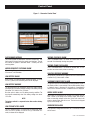
CONTROL PANEL INTERFACE
Upon power up, this controller will go through a system self test
which will check for the presence of utility voltage on the DC
circuits. This is done to prevent damage if the installer mistakenly
connects AC utility power sense wires into the DC terminal block.
If utility voltage is detected, the controller will display a warning
message and lock out the generator, preventing damage to the
controller. Power to the controller must be removed to clear this
warning.
USING THE AUTO/OFF/MANUAL SWITCH
the switch set to AUTO, the engine may
crank and start at any time without warning.
With
Such automatic starting occurs when utility
2.
3.
NOTE:
DAMAGE CAUSED BY MISWIRING OF THE INTERCONNECT
WIRES IS NOT WARRANTABLE!
This test will be performed each time the controller is powered
up.
Next, the user must enter the minimum settings to operate. These
settings are current date and time and exercise day and time. The
maintenance intervals will be initialized (i.e. started) the first time
the clock is set. If the clock is never set at power up, the maintenance intervals will be reset every time power is applied.
If a subsequent power loss (loss of battery power) occurs the
Installation assistant will operate upon power restoration. The self
test routine will be run and then the customer will be required to
re-enter the time and date, as this is not retained during a power
loss. The unit will not require re-activation.
ACTIVATE THE GENERATOR
DISPLAY INTERFACE MENUS
When battery power is applied to the generator during the installation process, the controller will turn ON and the LCD screen will
illuminate. However, the generator still needs to be activated before
it will automatically run in the event of a power outage.
The LCD display is organized as detailed below:
• The “Home” page, this page is the default page which will be
displayed if no keys are pressed for 30 seconds. This page
normally shows the current Status message and the current
date and time. The highest priority active Alarm and/or Warning
will be automatically posted on this page as well as flashing
the backlight when such an event is detected. In the case of
multiple Alarms or Warnings, only the first message will be
displayed. To clear an Alarm or Warning, see the Protection
Systems section - Clear Alarm.
• The display backlight is normally off. If the user presses any
key, the backlight will come on automatically and remain on for
30 seconds after the last key was pressed.
• The “Main Menu” page will allow the user to navigate to all other
pages or sub-menus by using the Left/Right and Enter keys.
This page can be accessed at any time with several presses of
the dedicated Escape key. Each press of the Escape key takes
you back to the previous menu until the main menu is reached.
This page displays the following options: HISTORY; STATUS;
EDIT; AND DEBUG. (See the Appendix - "Menu System".)
Activating the generator is a simple one time process that is guided
by the controller screen prompts. Once the product is activated,
the controller screen will not prompt you again, even if you disconnect the generator battery.
To obtain the activation code, record the generator serial number
and log onto www.activategen.com or call 1-888-9ACTIVATE and
follow the steps to retrieve the activation code.
After obtaining your activation code, please complete the following
steps at the generator’s control panel in the Activation Chart on the
following page.
NOTE:
The generator will only run in manual until the passcode has
been entered.
8-1
CntrlNexusus001 Rev. D 04/11
1.
Utility voltage must be turned on and present at the N1 and N2
terminals inside the generator control panel for this test to be
performed and pass.
power source voltage drops below a preset
level or during the normal exercise cycle. To
prevent possible injury that might be caused
by such sudden starts, always set the switch
to OFF and remove the fuse before working on or around the generator or transfer
switch. Then, place a “DO NOT OPERATE”
tag on the generator panel and on the transfer switch.
“AUTO” Position – Selecting this switch activates fully automatic system operation. It also allows the unit to automatically start and exercise the engine every seven days with the
setting of the exercise timer (see the Setting the Exercise
Timer section).
“OFF” Position – This switch position shuts down the engine.
This position also prevents automatic operation.
“MANUAL” Position – Set the switch to MANUAL to crank
and start the engine. Transfer to standby power will not occur
unless there is a utility failure.
Control Panel
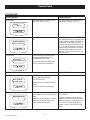
ACTIVATION CHART
CHOOSE LANGUAGE
TROUBLESHOOTING
Display Reads:
Language
English
Escape
Use ARROW keys to scroll to desired language. Press ENTER to select.
If the wrong language is chosen, it can be
changed later using the “edit” menu.
Press ENTER to begin the activation process.
If ESCAPE is pressed instead of ENTER,
your generator will only run in manual mode
(for test purposes) and NOT ACTIVATED will
be displayed. You will need to remove the
generator control panel fuse AND disconnect
the T1, N1 and N2 connector in the external
connection box (if equipped); or disconnect
utility input (main breaker) to the transfer
switch for 3-5 seconds and reconnect, then
begin with Step 1.
+
Enter
Display Reads:
Activate me (ENT) or
ESC to run in manual
Escape
Enter
Display Reads:
To Activate go to
www.activategen.com
Escape
If you do not have your activation code,
go to www.activategen.com or call
1-888-9ACTIVATE (922-8482).
If you already have your activation code,
wait 3-5 seconds for the next display.
Enter
ENTER ACTIVATION CODE (Passcode)
Display Reads:
TROUBLESHOOTING
Use ARROW keys to scroll and find the first
number of your Activation Code.
Serial 123456789
Passcode XXXXX +/-
Press ENTER to select.
Escape
Use ESCAPE to correct previous digits.
Enter
Display Reads:
“SELECT HOUR (0-23)”
“6
+”
Escape
Enter
Repeat this step until all digits have been
entered.
Activation is complete when all digits are
entered above and your screen shows this
display.
Follow the controller prompts to continue
setting the time function. Refer to your
Owner’s Manual with questions.
8-2
What happens if “Wrong Passcode Try
Again” appears?
Re-enter the activation code. If a second
attempt is unsuccessful, check the number
against the code given on activategen.com.
If it is correct and the generator will not
accept it, contact 1-888-9ACTIVATE (9228482).
CntrlNexus001 Rev. D 04/11
Control Panel
INSTALLATION ASSISTANT
• If utility is still lost after the “line interrupt period”, run the engine
up to normal RPM and transfer the load. At this time the controller will exit the exercise routine and assume full automatic
operation.
Interconnect System Self Test Feature (follow the on-screen
prompts).
Upon power up, this controller will go through a system self test
which will check for the presence of utility voltage on the DC
circuits. This is done to prevent damage if the installer mistakenly
connects AC utility power sense wires into the DC terminal block.
If utility voltage is detected, the controller will display a warning
message and lock out the generator, preventing damage to the
controller. Power to the controller must be removed to clear this
warning.
USER ADJUSTABLE SETTINGS
Setting
Factory
Default
Minimum
Setting
Maximum
Setting
Increment
Exercise
time
2 pm
00:00 (12 am)
23:59
(11:59 pm)
1 min
Exercise
day
Wed
Sun
Sat
1 day
Current
Time
12 am
00:00 (12 am)
23:59
(11:59 pm)
1 min
Current
Day
Sun
Sun
Sat
1 day
Current
Month
Jan
Jan
Dec
1 month
Current
Year
2008
2008
2100
1 year
Language
English
French
Spanish
N/A
Contrast
80%
0%
100%
1%
Utility voltage must be turned on and present at the N1 and N2
terminals inside the generator control panel for this test to be
performed and pass.
NOTE:
DAMAGE CAUSED BY MISWIRING OF THE INTERCONNECT
WIRES IS NOT WARRANTABLE!
This test will be performed each time the controller is powered
up.
Upon first power up of the generator, the display interface will
begin an installation assistant. The assistant will prompt the user
to set the minimum settings to operate. These settings are simply:
Current Date/Time and Exercise Day/Time. The maintenance intervals will be initialized when the exercise time is entered.
FUEL CONVERSION
The exercise settings can be changed at any time via the "EDIT"
menu (see Appendix, "Menu System").
For fuel conversion steps, refer to the GenSpec section,
RECONFIGURING THE FUEL SYSTEM.
If the 12 volt battery is disconnected or the fuse removed, the
Installation Assistant will operate upon power restoration. The
only difference is the display will only prompt the customer for the
current Time and Date.
OPERATION
IF THE INSTALLER TESTS THE GENERATOR PRIOR TO
INSTALLATION, PRESS THE “ENTER” KEY TO AVOID SETTING
UP THE EXERCISE TIME. THIS WILL ENSURE THAT WHEN
THE CUSTOMER POWERS UP THE UNIT, HE WILL STILL BE
PROMPTED TO ENTER AN EXERCISE TIME.
This system is intended to supply standby power in the event of a
utility failure. The control system will monitor the utility voltage to
determine if stand-by power is required. Should the utility voltage
fail, the generator will start and run normally, detaching from the
utility and supplying the customer load from the generator. When
utility power returns, the controller will re-transfer the customer
load back to utility and shut down the generator.
SETTING THE EXERCISE TIMER
This generator is equipped with an exercise timer. Once it is set,
the generator will start and exercise every seven days, on the day
of the week and at the time of day specified. During this exercise
period, the unit runs for approximately 12 minutes and then shuts
down. Transfer of loads to the generator output does not occur
during the exercise cycle unless utility power is lost.
AUTOMATIC TRANSFER OPERATION
To select automatic operation, do the following:
1.
Make sure the transfer switch main contacts are set to their
UTILITY position, i.e., loads connected to the utility power
source.
2. Be sure that normal UTILITY power source voltage is available to transfer switch terminal lugs N1 and N2 (Refer to the
Electrical Data section).
3. Set the generator’s AUTO/OFF/MANUAL switch to AUTO.
4. Set the generator’s main circuit breaker to its ON (or CLOSED)
position.
With the preceding steps complete, the generator will start automatically when utility source voltage drops below a preset level.
After the unit starts, loads are transferred to the standby power
source. Refer to the Sequence of Automatic Operation section.
The standard start sequence will be initiated.
• All 1800 rpm units will exercise at 1400 RPM
• All 3600 rpm units will exercise at 1800 RPM
If utility is lost during exercise the controller will do the following:
• Wait for the “line interrupt period” for utility to return. If utility
returns within the “line interrupt period”, continue to exercise
at low RPM.
8-3
CntrlNexus001 Rev. D 04/11
LOW SPEED EXERCISE
Control Panel
SEQUENCE OF AUTOMATIC OPERATION
MANUAL START
Initial Conditions: Generator in Auto ready to run, load being supplied by the Utility Source through the transfer switch.
Allows the user to start and run the generator manually.
1.
2.
3.
4.
Transfer of the load to the generator will occur if utility is lost while
the unit is running in the manual mode (only if activated).
When the utility voltage fails (falls below 60% of nominal), a
10-30 second (programmable) “line interrupt” delay timer is
started. The factory set time delay is 10 seconds. If at the
end of the line interrupt time the utility voltage is above 60%
the engine will not crank. If the utility voltage is still below
the 60% of nominal at the end of the line interrupt time, the
unit will crank and start. If the unit cranks for more than 10
seconds and the utility voltage rises above 80% of nominal
(programmed pickup voltage) and the unit has not started, the
crank cycle will abort.
As soon as the unit starts a 5 second “warm-up” timer is initiated. When the warm-up timer expires the control will transfer
the load to the generator (through the RTS switch) if the utility
voltage is less than 80% of nominal. If the utility voltage is
greater than the 80% of nominal at the end of the warm-up
time the load will not be transferred to the generator and a one
minute low-speed cool down period will start. At the end of
the one minute cool down period the generator will stop.
Once the unit is running and the switch has transferred the
load to the generator the unit will monitor utility voltage.
When utility voltage returns (above the programmable pickup
voltage, normally 80% of nominal), a 15 second “Return to
Utility” timer will start. At the end of the return to utility time,
if the utility voltage is still above the pickup voltage, the unit
will transfer the load back to the utility source and run the unit
through a one minute cool down period. When the cool down
period is over the unit will shut down and be ready for the next
outage.
If during the cool down period utility voltage should fall below
60% of nominal the 5 second warm-up timer is initiated and
the unit will transfer the load back to the generator and continue to monitor the utility.
ALARM AND WARNING MESSAGES
Alarms are defined as “Latching” which means they must be
cleared before the alarm message on the screen will clear. They
can be of type “Shutdown” or not and are logged in the alarm log.
Alarms are all annunciated on the display).
Warnings are “Non Latching” meaning the message automatically clears when the warning condition goes away. Warnings can
not be of type “Shutdown” but they are logged in the alarm log.
Warnings are all annunciated on the display.
LOW OIL PRESSURE SHUTDOWN ALARM
There is a 10 second delay before oil pressure is monitored.
HIGH COOLANT TEMPERATURE SHUTDOWN ALARM
There is a 10 second delay before engine temperature is monitored.
Once running there is a 1/4 second delay before shut down. The
limit is set at 125° C or 257° F.
OVERCRANK SHUTDOWN ALARM
Occurs if the engine has not started within the specified crank
cycle.
OVERSPEED SHUTDOWN ALARM
Warning indicator is measured and calculated by the microprocessor. Overspeed is defined as +20% of nominal engine speed for 3
seconds, or +25% immediate.
CRANK CYCLES AND OVERCRANK SHUTDOWN
If the unit fails to start during a cranking period it will display the
Overcrank Shutdown Alarm. The system will control the cranking
cycles as follows:
Nominal engine speed = 60.0 Hz
RPM SENSOR FAILURE SHUTDOWN ALARM
The first crank cycle is a 16 second crank time followed by a 7
second rest. The next 5 cycles will be 7 seconds of cranking time
each followed by a 7 second rest time.
During cranking: If the board does not see a valid RPM signal
within four (4) seconds of cranking it will shut down and lock out
on RPM sensor loss.
If the unit fails to start by the end of the 6 crank/rest cycles
the Overcrank Shutdown Alarm will display and the unit will not
attempt to crank until the alarm is reset.
During running: If the RPM signal is lost for one full second the
board will shut the engine down, wait 15 seconds, then re-crank
the engine if in AUTO, it will not re-crank in MANUAL.
If no RPM signal is detected within the first four (4) seconds of
cranking, the control board will shut the engine down and latch out
on RPM sensor loss.
AUTO START
This unit is designed to automatically start in the event of a utility failure or brown out condition. Brown out is defined as utility
voltage less than 60% nominal, while utility is considered good
when it is restored to at least the pickup value, 80% of nominal.
These levels are fixed. The “Line Interrupt period” is an adjustable
parameter by the dealer. If 2-wire start mode is activated, the unit
will start when 2-wire start is active.
If the RPM signal is detected the engine will start and run normally.
If the RPM signal is subsequently lost the control board will try
two more re-cranks before latching out and flashing the RPM
Sensor Failure message (if it is in AUTO).
8-4
CntrlNexus001 Rev. D 04/11
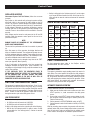
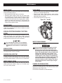
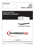
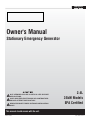
Control Panel
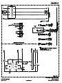
Figure 1 – Generator Control Panel
CHECK ENGINE MESSAGE
MISSING CAM PULSE ALARM
The control system has detected an emissions related fault. This
fault cannot be cleared using the control panel interface. The unit
will continue to operate in automatic mode. Contact your local
servicing dealer.
This is a shutdown alarm. The alarm will activate after five (5)
seconds of continuously missing cam pulses.
UNDER-FREQUENCY SHUTDOWN ALARM
This is a shutdown alarm. The alarm will activate after 12 consecutive revs where crank pulses are missing.
MISSING CRANK PULSE ALARM
After starting, if the generator stays under frequency for more than
30 seconds, it will shutdown.
LOW FUEL PRESSURE WARNING
Fuel pressure is monitored by a digital sensor with a fixed setpoint
of below five (5) inches water column.
LOW BATTERY ALARM
While running, if the average battery voltage falls below 11.9 volts
for one (1) minute, the low battery alarm will be displayed.
GOVERNOR SENSOR FAULT ALARM
The governor position is monitored by an analog feedback signal. If
the throttle position is seen outside of the normal operating range,
a shutdown alarm is displayed. If the throttle is commanded to
move, and no movement is seen, a shutdown alarm is displayed.
LOW BATTERY WARNING
The microprocessor will continually monitor the battery voltage
and display the Low Battery Voltage message if the battery voltage
falls below 12.2 Volts for one (1) minute.
WIRING ERROR ALARM
No other action is taken on a low battery warning condition. The
warning will automatically clear if the battery voltage rises above
12.2 volts.
When power is first apllied to the contoller, the software will perform a check on the wiring of the transfer output, and ensure it
does not have high voltage on the wire. If this is the case, it will
signal a miswire alarm and will not run. The test can be skipped
by use of the escape key.
NOTE:
The battery sentinel is a separate feature that monitors battery
condition.
UNDERVOLTAGE ALARM
LOW COOLANT LEVEL ALARM
If the generator voltage falls below 60% for >5 seconds, an alarm
will be issued.
8-5
CntrlNexus001 Rev. D 04/11
This is a shutdown alarm. The sensor will be continuously monitored. If an error condition is seen for five (5) consecutive seconds, the alarm will be displayed.
Control Panel
OVERVOLTAGE ALARM
ALARM CANCEL
If the generator voltage rises above 110% for >3 seconds, an
alarm will be issued.
If the generator voltage rises above 130% for >0.2 seconds, an
alarm will be issued.
When the generator is shut down due to a latching alarm, the Auto
/Off/ Manual switch must be set to the off position and the ENTER
key pressed to unlatch any active fault and clear the corresponding
fault alarm message.
INTERNAL FAILURE SHUTDOWN ALARM
COMMON ALARM RELAY
Any internal failure that can be detected such as corrupted
firmware will cause this shutdown alarm. This alarm cannot be
cleared.
The common alarm relay will be activated if there is a shutdown
alarm. It will not activate on warnings or indicate that the Auto/Off/
Manual switch is in the OFF position. The OFF position will clear
the alarms and the relay. The relay will not be used to indicate a
generator is not activated.
CANBUS ALARM
The common alarm connections are wired to a set of potentialfree (dry) contacts on the Nexus controller board. These Normally
Open (N.O.) contacts close when an alarm condition occurs and
are used to activate a remote signaling device. The circuit is rated
for a maximum of 130mA at 24 VDC. The connections are a short
set of free hanging wires that exit the engine harness loom directly
behind the Nexus Control Panel and are labeled numbers 209 and
210.
Where applicable, if the Canbus communications link fails to communicate, a “Canbus Alarm” will be generated. This only applies
to systems with external ignition modules. The alarm may be
generated if:
1.
2.
3.
4.
5.
6.
The physical link is broken.
The Ignition Module fails or resets.
The Nexus Controller fails or resets.
Having the Battery Chargers 120 VAC connected without a
battery installed.
A blown 10 amp Ignition Module fuse (approximately 12
inches away from the starter).
A blown 25 amp system fuse (located approximately 12
inches away from the DC alternator).
NOTE:
MAINTENANCE ALERTS
Maintenance alerts will be provided for these conditions (see the
Maintenance Alert Chart).
SERVICE SCHEDULE ‘A’
The “Canbus Alarm” will not clear on its own. To clear the
alarm, press the “enter” key to acknowledge the alarm. The
alarm will clear and if the fault is still present, the alarm will
reoccur.
IGNITION ALARM
When an ignition alarm occurs, a generic message “Ignition Fault”
will be displayed as the fault code.
MAINTENANCE WARNING
Inspect Accessory drive alert
1yr /100hrs
Coolant change & flush
1yr /100hrs
Inspect spark plugs alert
1yr /100hrs
Change oil & filter alert
1yr /100hrs
Inspect battery alert
1yr /100hrs
Change / Inspect air filter alert
1yr /100hrs
SERVICE SCHEDULE ‘B’
When a maintenance period expires, a warning message will be
posted. The warning can be reset by hitting the Enter key. Resetting
will clear the warning and reset the maintenance counters for the
condition annunciated. The history log will reflect the maintenance
warning.
Change / Inspect spark plugs alert
8-6
2yr/ 250hr
CntrlNexus001 Rev. D 04/11
Control Panel
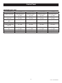
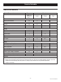
MAINTENANCE ALERT CHART
CONDITION
1.6 CHERY
2.4/1800 MITSU
2.4/3600 MITSU
4.2 FORD
Change oil & filter alert
3mo/30hrs break-in
1yr/100hrs
3mo/30hrs break-in
1yr/100hrs
3mo/30hrs break-in
1yr/100hrs
3mo/30hrs break-in
1yr/100hrs
Inspect/clean air inlet &
exhaust alert
3mo/30hrs break-in
6mo/50hrs
3mo/30hrs break-in
6mo/50hrs
3mo/30hrs break-in
6mo/50hrs
3mo/30hrs break-in
6mo/50hrs
Change / Inspect air filter
alert
1yr/100hr
1yr/100hr
1yr/100hr
1yr/100hr
Inspect spark plugs alert
1yr /100hrs
1yr /100hrs 1yr /100hrs
1yr /100hrs
1yr /100hrs
Change / Inspect spark
plugs alert
2yr/ 250hr
2yr/ 250hr
2yr/ 250hr
2yr/ 250hr
Inspect Accessory drive
alert
3mo/30hrs break-in
1yr /100hrs
3mo/30hrs break-in
1yr /100hrs
3mo/30hrs break-in
1yr /100hrs
3mo/30hrs break-in
1yr /100hrs
Coolant change & flush
1yr /100hrs
1yr /100hrs
1yr /100hrs
1yr /100hrs
Inspect battery alert
1yr /100hrs
1yr /100hrs
1yr /100hrs
1yr /100hrs
CntrlNexus001 Rev. D 04/11
8-7
CntrlNexus001 Rev. D 04/11
8-8
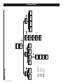
ENTER
+/-
ESC
ALARM LOG
RUN LOG
ESC
Use the “ENTER” key
to select items or
enter data.
Use the “+/-” key
to navigate through
the menu.
Press the “ESCAPE” key
to jump back up through
the menu levels.
HISTORY
MENU SYSTEM
STATE
ESC
BATTERY
VOLTAGE
GENERATOR
FREQUENCY
ENGINE
RPM
ENGINE
HOURS
DISPLAY
STATUS
COMMAND
ESC
VERSIONS
ACTIVATION
MAIN MENU
ESC
RESET
MAINTENANCE
EXERCISE
TIME/SPEED
TIME/DATE
LANGUAGE
EDIT
ESC
INPUTS
OUTPUTS
DEBUG
DISPLAYS
ESC
QT TEST
Control Panel
Operation
STATIONARY EMERGENCY
GENERATOR CONTROL AND
OPERATION
not crank the engine continuously for longer than 30 seconds, or the heat may
nDo
damage the starter motor.
Refer to the appropriate control panel operator’s manual for this
unit.
• Let engine stabilize and warm up.
• Check all applicable instrument and gauge readings. When
certain that all readings are correct, move the transfer switch
manual handle to the STANDBY (or EMERGENCY STANDBY)
position, i.e., load circuits supplied by the generator.
• Set the generator’s main line circuit breaker to its ON (or
CLOSED) position.
• Load circuits are now powered by the generator.
OPERATING UNIT WITH MANUAL
TRANSFER SWITCH
If the Stationary Emergency Generator was installed in conjunction
with a transfer switch capable of manual operation only, the following procedure applies. A manually operated transfer switch is
one that will not provide automatic start-up and does not include
an intelligence circuit.
RETRANSFER AND SHUTDOWN
For additional information, refer to the applicable control panel
manual for this unit, as well as any literature pertaining to the
specific transfer switch.
ENGINE START-UP AND TRANSFER
For additional information, refer to the applicable control panel
manual for this unit, as well as any literature pertaining to the
specific transfer switch.
To transfer the load back to the utility power source and shut down
the generator, follow these directions:
• Set the generator’s main line circuit breaker to its OFF (or OPEN)
position.
• Manually move the transfer switch handle to its UTILITY
(NORMAL) position, i.e., load circuits connected to the utility.
• Turn ON the utility power supply to the transfer switch, using
the means provided (such as the utility power source main line
circuit breaker).
• Let the generator run at no-load for a few minutes to stabilize
internal temperatures.
• Shut down the generator.
Maintenance Disconnect Switch and the
nThe
AUTO/OFF/MANUAL switches (if so equipped)
must be set properly, or the generator will
crank and start as soon as the utility power to
the transfer switch is turned off. Refer to applicable control panel and transfer switch manuals
for more information.
not proceed until certain that utility source
nDo
voltage is available to the transfer switch and
the transfer switch main contacts are set to
OPERATING UNIT WITH AUTOMATIC
TRANSFER SWITCH
UTILITY.
power supplies to the transfer switch have been
If the Stationary Emergency Generator has been installed with an
automatic transfer switch, the engine may be started and stopped
automatically or manually.
Do not attempt manual operation until all
positively turned off, or extremely dangerous possibly lethal - electrical shock will result.
NOTE:
Transfer switch enclosure doors should be kept
closed and locked. Only authorized personnel
should be allowed access to the transfer switch
interior. Extremely high and dangerous voltages
are present in the transfer switch.
In order to transfer load from the utility source to the generator,
follow these directions:
Refer to the applicable manual for your transfer switch and to
“Transfer Switch Start Signal Connections”. In addition, please
note the dangers under “Engine Start-up and Transfer.”
• Turn OFF or disconnect the utility power circuit to the transfer
switch, using the means provided (such as the utility source
main line circuit breaker).
• Set the transfer handle to its UTILITY (NORMAL) position with
load circuits connected to the utility power supply.
• Set the generator’s main line circuit breaker to its OFF (or OPEN)
position.
• Start the generator.
Oper001 Rev. D 05/10
9-1
Maintenance
GENERAL MAINTENANCE
Refer to the Service Schedule for engine oil and filter change frequencies.
Drain the oil while the engine is still warm from running. This
means warm up the engine, shut it down and drain immediately
as follows:
•
•
•
•
Before working on the Stationary Emergency
Generator, ensure the following:
The AUTO/OFF/MANUAL switch is in the OFF position.
The control panel fuse has been removed from the control
box.
The 120VAC supply to the battery charger is switched OFF.
The negative battery cable has been removed.
1.
2.
3.
CHECK ENGINE OIL
4.
Check engine crankcase oil level (Figure 10.1) according to the
Service Schedule and SIB10-10-L24G.
•
•
•
•
5.
Remove oil dipstick and wipe dry with a clean, lint-free cloth.
Install oil dipstick, then remove again.
Oil should be between FULL and ADD marks.
If oil level is below the dipstick ADD mark, remove oil fill cap-.
Add the recommended oil to bring oil level up to the FULL
mark. DO NOT FILL ABOVE THE “FULL” MARK. See “Engine Oil
Recommendations” for recommended oils.
6.
Remove the drain hose from its retaining clip or cut the zip-tie
securing the oil drain hose.
Loosen and remove OIL DRAIN HOSE CAP. Drain oil completely into suitable container.
When all oil has drained, install and tighten OIL DRAIN HOSE
CAP and secure drain hose with a new zip-tie, or place the
hose in its retaining clip.
Turn OIL FILTER (Figure 10.1) counterclockwise and remove.
Properly dispose of old filter.
Apply light coating of new engine oil to seal of new oil filter. Install FILTER and tighten by hand only. DO NOT OVER
TIGHTEN.
Remove OIL FILL CAP and add recommended oil. Crankcase
oil capacity is listed in the "Specifications" section.
refilling the crankcase with oil, always
check oil level on dipstick. NEVER OPERATE
nAfter
ENGINE WITH OIL BELOW THE DIPSTICK “ADD”
Figure 10.1 - Oil Dipstick and Oil Fill Cap
7.
8.
Oil Fill Cap
9.
MARK.
Start engine and check for oil leaks.
Shut OFF engine and wait 10 minutes for the oil to settle down
into the oil pan. Recheck oil level on dipstick. DO NOT fill
above the dipstick "FULL" mark.
Dispose of used oil at a proper collection center.
COOLING INTAKE/OUTLET
Air intake and outlet openings in the generator compartment must
be open and unobstructed for continued proper operation. This
includes such obstructions as high grass, weeds, brush, leaves
and snow.
Oil
Dipstick
Without sufficient cooling and ventilating air flow, the engine/generator quickly overheats, which causes it to shut down. (See the
installation diagram.)
hot and remains hot after shutdown.
extremely
High grass, weeds, brush, leaves, etc. must
The exhaust system parts from this product get
Oil Filter
remain clear of the exhaust. Such materials may
ignite and burn from the heat of the exhaust
system.
CHANGING ENGINE OIL
INSPECT COOLING SYSTEM
• Inspect engine cooling system. See the Service Schedule.
• Check hoses for damage, deterioration, leaks, etc. Correct any
discrepancies found.
• Check hose clamps for tightness.
oil may cause burns. Allow engine to cool
before draining oil. Avoid prolonged or repeatnHot
ed skin exposure with used oil. Thoroughly
wash exposed areas with soap.
Maint025 Rev. A 05/10
10-1
Maintenance
ENGINE COOLANT
CHECK FAN BELT
Check coolant level in coolant recovery bottle. See the Specifications
and Service Schedule sections.
• Inspect fan belts every year. Replace any damaged, deteriorated, worn or otherwise defective belt.
• Check fan belt tension. Thumb pressure, exerted midway
between pulleys, should deflect about 3/8 to 5/8 of an inch.
Adjust belt tension as required.
• Check fan belt alignment (see Figure 10.2).
• Add recommended coolant mixture as necessary.
• Periodically remove radiator pressure cap (only when engine
has cooled down) to make sure the coolant recovery system
is functioning properly. Coolant should be at bottom of radiator filler neck. If coolant level is low, inspect gasket in radiator
pressure cap. Replace cap, if necessary. To have pressure cap
tested, contact a Service Facility. Inspect cooling system and
coolant recovery system for leaks.
Figure 10.2 – Fan Belt
COOLANT CHANGE
Every year, have a service facility drain, flush and refill the cooling
system. See the Specifications and Service Schedule for cooling
system recommendations.
OVERLOAD PROTECTION FOR ENGINE DC ELECTRICAL
SYSTEM
Engine cranking, start up and running are controlled by a solid
state Engine Controller circuit board. Battery voltage is delivered
to that circuit board via the control panel fuse. This overcurrent
protection device will open if the circuit is overloaded.
INSPECT ENGINE GOVERNOR
n
If a circuit breaker opens or a fuse element
melts, find the cause of the overload before
resetting the circuit breaker or replacing the
fuse.
Visually inspect electronic governor.
not attempt to adjust the governor. Only
qualified service facilities should adjust the
nDo
governor. Excessively high operating speeds
EXERCISE SYSTEM
Starts the Stationary Emergency Generator engine once every
seven days and lets it run for 12 minutes.
are dangerous and increase the risk of personal
injury. Low speeds impose a heavy load on the
engine when adequate engine power is not
available and may shorten engine life. Correct
rated frequency and voltage are supplied only
at the proper governed speed. Some connected
electrical load devices may be damaged by
incorrect frequency and/or voltage. Only qualified service technicians should adjust the governed speed.
PERFORM VISUAL INSPECTION
Complete a thorough visual inspection of the entire engine-generator monthly. Look for obvious damage, loose, missing or corroded
nuts, bolts and other fasteners. Look for fuel, oil or coolant leaks.
INSPECT EXHAUST SYSTEM
Inspect the exhaust system at least once every year. Check all
exhaust system pipes, mufflers, clamps, etc. for condition, tightness, leaks, security, damage.
CHANGING THE ENGINE AIR FILTER
To replace the engine air filter, remove the air filter cover and
replace the air filter making sure it is positioned properly before
reattaching the cover (Figure 10.3).
See the Service Schedule for air filter maintenance.
10-2
Maint025 Rev. A 05/10
Maintenance
Figure 10.3 – Engine Air Filter
electrolyte fluid is an extremely corronBattery
sive sulfuric acid solution that can cause severe
burns. Do not permit fluid to contact eyes, skin,
clothing, painted surfaces, etc. Wear protective
goggles, protective clothing and gloves when
handling a battery. If fluid is spilled, flush the
affected area immediately with clear water.
Air Filter
not use any jumper cables or booster battery to crank and start the generator engine. If
nDo
the battery has completely discharged, remove
it from the generator for recharging.
sure the AUTO/OFF/MANUAL switch is set
the OFF position, before connecting the
nBetobattery
cables. If the switch is set to AUTO or
MANUAL, the generator can crank and start as
soon as the battery cables are connected.
is turned OFF, or sparking may occur at the bat-
Be sure the 120VAC power supply to the battery
SPARK PLUGS
Reset the spark plug gap or replace the spark plugs as necessary.
1.
2.
3.
tery posts as the cables are attached and cause
an explosion.
Clean the area around the base of the spark plugs to keep dirt
and debris out of the engine. Clean by scraping or washing
using a wire brush and commercial solvent. Do not blast the
spark plugs to clean.
Remove the spark plugs and check the condition. Replace
the spark plugs if worn or if reuse is questionable. See the
“Service Schedule” section for recommended inspection.
Check the spark plug gap using a wire feeler gauge. See the
Specifications section for the required spark plug gap.
BATTERY REPLACEMENT
NOTE:
Unit DOES NOT include battery.
When supplying or replacing the battery, the recommended number and type of battery is listed in the Specifications Section.
NOTE:
BATTERY MAINTENANCE
The BCI number should be located directly on the battery.
The battery should be inspected per the Service Schedule section.
The following procedure should be followed for inspection:
BATTERY FLUID
2.
3.
Check battery electrolyte fluid based on the Service Schedule.
Fluid should cover separators in all battery cells. If fluid level is
low, add distilled water to cover tops of separators. DO NOT USE
TAP WATER IN BATTERY.
Inspect the battery posts and cables for tightness and corrosion. Tighten and clean as necessary.
Check the battery fluid level of unsealed batteries and, if
necessary, fill with DISTILLED WATER ONLY. DO NOT USE TAP
WATER IN BATTERIES.
Have the state of charge and condition checked. This should
be done with an automotive-type battery hydrometer.
CLEANING THE STATIONARY EMERGENCY GENERATOR
Keep the generator as clean and as dry as possible. Dirt and
moisture that accumulates on internal generator windings have an
adverse effect on insulation resistance.
Periodically clean generator exterior surfaces. A soft brush may be
used to loosen caked on dirt. Use a vacuum system or dry, low
pressure air to remove any accumulations of dirt. The generator is
housed inside an all-weather enclosure, clean the enclosure with a
soft, damp cloth or sponge and water.
gas. This gas can form an explosive mixture
Storage batteries give off explosive hydrogen
around the battery for several hours after
charging. The slightest spark can ignite the gas
and cause an explosion. Such an explosion can
shatter the battery and cause blindness or other
injury. Any area that houses a storage battery
must be properly ventilated. Do not allow smoking, open flame, sparks or any spark producing
tools or equipment near the battery.
Once each year have the generator cleaned and inspected by a
Service Dealer. That dealer will use dry, low pressure air to clean
internal windings.
Finally, have the insulation resistance of stator and rotor windings
checked. If insulation resistances are excessively low, the generator may require drying.
10-3
Maint025 Rev. A 05/10
1.
Service Schedule
SERVICE SCHEDULE
System / Component
Frequency
Procedure
Weekly - W
Monthly - M
Yearly - Y
Inspect
M
X
Oil Level
M
X*
Oil
Y
X**
Oil Filter
Y
X**
Change
Clean
Fuel
Fuel Lines & Connections
Lubrication
Cooling
Engine Coolant Lines & Connections
M
X
Engine Coolant Level
M
X
Engine Coolant
Y
Enclosure Louvers
W
X
Air Cleaner
Y
X
X***
Spark Plugs
Y
X
X***
Remove Corrosion, Ensure Dryness
M
X
X
Clean & Tighten Battery Terminals
M
X
X
Check Charge State
M
X
X***
Check Electrolyte Level
M
X
X***
M
X
X
X
Engine
Battery
General Condition
Vibration, Noise, Leakage, Temperature
Generator System
Complete Tune-up and System Inspection
Y
To be completed by an Authorized Service Dealer.
Footnotes
* Inspect the oil level monthly or every 12 hours during continuous operation.
** Change oil and oil filter after the first 30 hours of operation and then every 100 hours or annually thereafter, whichever occurs first.
Change sooner when operating under heavy load or in a dusty or dirty environment or in high ambient temperatures.
*** Replace as necessary.
SrvSchd004 Rev. B 05/10
11-1
Troubleshooting
TROUBLESHOOTING GUIDE
PROBLEM
CAUSE
CORRECTION
Engine won’t crank.
1. Control panel 7.5 amp fuse blown.
2. Loose or corroded or defective
battery cables.
3. Defective starter contactor.
4. Defective starter motor.
5. Dead or Defective Battery.
1. Replace fuse.*
2. Tighten, clean or replace
battery cables as necessary.*
3. Replace contactor.*
4. Replace starter motor.*
5. Remove, change or replace battery.*
Engine cranks but won't start.
1. Out of fuel.
2. Fuel solenoid (FS) is defective
3. Spark plugs defective.
1. Replenish fuel/turn on fuel valve.
2. Replace solenoid.*
3. Clean, regap or replace plugs.
Engine starts hard, runs rough.
1. Air cleaner plugged or damaged.
2. Defective spark plugs.
3. Fuel pressure incorrect.
1. Clean or replace as needed.
2. Clean, regap or replace plugs.
3. Confirm fuel pressure to regulator is as
recommended in SPECIFICATIONS.*
4. Confirm fuel pressure to regualtor is as
recommended in SPECIFICATIONS.*
5. Reconfigure the fuel system. (See
RECONFIGURING THE FUEL SYSTEM in
manual.*
4. Insufficient fuel supply.
5. Fuel system set to wrong fuel type.
Engine starts then shuts down.
1.
2.
3.
4.
5.
6.
7.
Engine oil level is low.
Engine is overheated.
Defective Low Oil Pressure Switch
Defective Coolant Temperature Switch
Defective Control Module circuit board.
Coolant Level is Low.
Defective Low Coolant Level Switch
1.
2.
3.
4.
5.
6.
7.
Check oil and add oil as needed.
Check cooling system for leaks.
Replace switch.*
Replace switch.*
Replace board.*
Repair leak - Add coolant.
Replace Switch.*
AUTO/OFF/MANUAL Switch at OFF,
engine continues to run.
1. Defective AUTO/OFF/MANUAL switch
2. Defective Control Module circuit board
1. Replace board.*
2. Replace board.*
No AC output from generator.
1. Main line circuit breaker is tripped/open.
2. Generator internal failure.
3. Thermal circuit breaker open.
1. Reset to ON/CLOSED.
2. *
3. Auto-reset - Wait 5 min. and attempt restart.
*Contact the nearest Dealer for assistance.
Trblsht003 Rev. B 05/10
12-1
Warranty
United States Environmental Protection Agency Warranty Statement
Warranty Rights, Obligations and Coverage
The United States Environmental Protection Agency (EPA) and Generac Power Systems, Inc. (Generac), are pleased to
explain the Emission Control System Warranty on your new stationary emergency engine. If during the warranty period, any
emission control system or component on your engine is found defective in materials or workmanship Generac will repair
your engine at no cost to you for diagnosis, replacement parts and labor provided it be done by an Authorized Warranty
Service Facility. Your emission control system may include parts such as the fuel metering, ignition, and exhaust systems
and other related emission related components listed below. Generac will warrant the emissions control systems on your
2009 and later model year engines provided there has been no abuse, neglect, unapproved modification or improper maintenance of your engine. For engines less than 130 HP the warranty period is two years from the date of sale to the ultimate
purchaser. For engines greater than or equal to 130 HP the warranty period is three year from the date of the engine being
placed into service.
Purchaser’s/Owner’s Warranty Responsibilities
As the engine purchaser/owner you are responsible for the following. 1.) The engine must be installed and configured in
accordance to the installation specifications. 2.) The completion of all maintenance requirements listed in your Owner’s
Manual. 3.) Any engine setting adjustment must be done in accordance and consistent with the instructions in the Owner’s
Manual. 4.) Any emission control system or component must be maintained and operated appropriately in order to ensure
proper operation of the engine and control system to minimize emissions at all times.
Generac may deny any, or all Emission Control System Warranty coverage or responsibility of the engine, or an emission
control system or component on your engine thereof, if it has failed due to abuse, neglect, unapproved modification or
improper maintenance, or the use of counterfeit and/or ‘gray market’ parts not made, supplied or approved by Generac.
Warranty service/scheduled maintenance can be arranged by contacting your selling dealer or an Authorized Warranty
Service dealer. The purchaser/owner shall be responsible for any expenses or other charges incurred for service calls and/or
transportation of the product to/from the inspection or repair facilities. The purchaser/owner shall be responsible for any and/
or all damages or losses incurred while the engine is being transported/shipped for inspection or warranty repairs.
Emission Related Parts Include the Following (if so equipped)
3) Ignition System including
a) Spark plug, b) Ignition module,
c) ignition coil, d) Spark plug wirers
4) Exhaust system
a) Catalyst assembly, b) Exhaust manifold,
c) Muffler, d) Exhaust pipe, e) Muffler gasket
5) Crankcase Breather Assembly including
a) Breather connection tube, b) PCV valve
6) Oxygen Sensor
7) Diagnostic Emission-Control System
13-1
EmsnWrnty001 Rev. C 05/10
1) Fuel Metering System
1.1) Gasoline Carburetor assembly and internal components
a) Fuel filter, b) Carburetor, c) Fuel Pump
1.2) Carburetion assembly and its components
a) Fuel controller, b) Carburetor and its gaskets,
c) Mixer and it gaskets, d) Primary gas regulator
e) Liquid vaporizer
1.3) Fuel Regulator
2) Air Induction System including
a) Intake pipe/manifold, b) Air cleaner
Warranty
United States Environmental Protection Agency Compliance Requirements
Purchaser’s/Owner’s Recordkeeping Responsibilities
The United States Environmental Protection Agency (EPA) and Generac Power Systems, Inc. (Generac), are pleased to
explain your recordkeeping requirements for compliance with Subpart JJJJ – Standards of Performance for Stationary Spark
Ignition Internal Combustion Engines as listed in the Electronic Code of Federal Regulations Title 40 Part 60. As the engine
purchaser/owner who operates and maintains their certified emergency stationary engine and emission control system
according to applicable emission related guidelines as specified in this Owner’s Manual you are required to meet the following notification and recordkeeping requirements to demonstrate compliance. 1.) Maintain documentation that the engine
is certified to meet emission standards. 2.) Recordkeeping of maintenance conducted. 3.) Recordkeeping of the provision
allowing natural gas engines to operate using propane for a maximum of 100 hours per year as an alternate fuel solely during emergency operations provided the engine is not certified to operate on propane. 4.) Meet all compliance notifications
submitted to the purchaser/owner and maintain all supporting documentation. 5.) Recordkeeping of hours of operation,
including what classified the operation as emergency and how many hours are spent for non-emergency operation. For
emergency engines greater than or equal to 130 HP, recordkeeping of hours of operation begins January 1, 2011. For emergency engines less than 130 HP, recordkeeping of hours of operation begins January 1, 2009; Engines are equipped with
non-resettable hour meters to facilitate recordkeeping.
Specific Air Quality Management or Air Pollution Control Districts may have different and additional record keeping/ reporting
requirements. Your permit to construct and/or operate the engine may be contingent upon compliance with those requirements. Check with your local Air Quality Management or Air Pollution Control District for specific requirements.
Emergency stationary internal combustion engines (ICE) may be operated for the purpose of maintenance checks and readiness testing, provided that the tests are recommended by Federal, State or local government, Generac, or the insurance company associated with the engine. Maintenance checks and readiness testing of such units is limited to 100 hours per year.
There is no time limit on the use of emergency stationary ICE in emergency situations. The purchaser/owner may petition the
Administrator for approval of additional hours to be used for maintenance checks and readiness testing, but a petition is not
required if the owner maintains records indicating that Federal, State, or local standards require maintenance and testing of
emergency ICE beyond 100 hours per year. Emergency stationary ICE may operate up to 50 hours per year in non-emergency situations, but those 50 hours are counted towards the 100 hours per year provided for maintenance and testing. The 50
hours per year for non-emergency situations cannot be used for peak shaving or to generate income for a facility to supply
power to an electric grid or otherwise supply power as part of a financial arrangement with another entity. For purchaser/
owner of emergency engines, any operation other than emergency operation, maintenance and testing, and operation in nonemergency situations for 50 hours per year, as permitted in this section is prohibited.
If you operate and maintain your certified emergency stationary SI internal combustion engine and emissions control systems in accordance with the specifications and guidelines in the Owner’s Manual, EPA will not require engine performance
testing. If not, your engine will be considered non-certified and you must demonstrate compliance according to Subpart JJJJ
– Standards of Performance for Stationary Spark Ignition Internal Combustion Engines as listed in the Electronic Code of
Federal Regulations Title 40 Part 60.
Emission-Related Installation Instructions
Your certified emergency stationary engine has pre-set emission control systems or components that require no adjustment.
Inspection and replacement of an emissions related component is required to be done in accordance with the requirements
cited in the United States Environmental Protection Agency Warranty Statement or can be arranged by contacting your selling dealer or an Authorized Warranty Service dealer. Failing to follow these instructions when installing a certified engine in a
piece of nonroad equipment violates federal law 40 CFR 1068.105 (b), subject to fines or penalties as described in the Clean
Air Act.
13-2
EmsnWrnty001 Rev. C 05/10
1
0F9677
0G0056
0G0959
0G1155
0G1931
0G2101
0G3734
0G6562
0G6564
1
1
1
1
1
1
1
1
1
ROTOR-2390-45KD1 CPL
ROTOR-2390-35KD1 CPL
ROTOR-2390-45KD1 CPL (G2)
ROTOR-2390-35KD1 CPL (G2)
ROTOR 25KW 3PH DIRECT 390 1800
ROTOR 25KW 1PH DIRECT 390 1800
RTR-2390-60KD2 CPL
RTR 390 35AD1 CPL
RTR 390 35KD1 CPL
2
0F9664
0G0057
0G0058
0G0059
0G0183
0G0184
0G1932
0G2098
0G2099
0G2100
0G3736
0G3737
0G3738
0G6104
0G6563
0G6565
0G6566
0G6567
0H0201
0H1299
0H1300
0H1301
1
1
1
1
1
1
1
1
1
1
1
1
1
1
1
1
1
1
1
1
1
1
STATOR-390 45K 2P 1PH DIRECT
STATOR-2390-35AD1 CPL
STATOR-2390-35KD1 CPL
STATOR-2390-35GD1 CPL
STATOR-2309-45KW 2P 3PH 208V
STATOR-2309-45-KD1 CPL
ASSY STR 390 25GD3 CPL
ASSY STR 390 25AD1 CPL
ASSY STR 390 25KD3 CPL
ASSY STR 390 25JD3 CPL
ASSY STR 2390 60AD2 CPL
ASSY STR 390 60KW 2P 3PH 208V
ASSY STR 390 60KW 2P 3PH 480V
STR-2390--45JD1 CPL
STR 390 35AD1 CPL
STR 390 35GD1 CPL
STR 390 35KD1 CPL
STR 390 35JD1 CPL
STR-2390--60JD2 CPL
ASSY STR 390 36AD1 CPL
ASSY STR 390 36JD1 CPL
ASSY STR 390 36 GD1 CPL
3
4
5
6
7
8
0C9708
SEE ENGINE EV
SEE ENGINE EV
0F5767B
0E5706
0F7874
0F7874A
0G0587
038150
023454
077043E
04576100BU
052646
043123
051779
0A2601
072879
0F8408
046526
0C3992
022264
047248
070892
0G0588
077043A
056326
REF
REF
REF
1
1
1
1
1
4
1
1
4
4
4
4
1
1
4
4
4
4
1
1
1
1
1
9
10
11
12
13
14
15
16
17
18
19
20
21
22
23 *
24 *
25
26
27
INSTR HYPOT TEST (NOT SHOWN)
ENGINE ADAPTER
FLEXPLATE
ASSY FLYWHEEL CPL W/40MM FAN B
REAR BEARING CARRIER 390/DRCT
ASSY BRUSH HOLDER 390/HSB
ASSY BRUSH HOLDER 390/HSB
GUARD REAR BEARING CARRIER
WASHER FLAT #8 ZINC
KEY WOODRUFF #E
CONDUIT FLEX 1.0" ID (35” LG)
STUD M14-2.0 570 G5 ZINC
WASHER FLAT M14
WASHER LOCK M14
NUT HEX M14-2.0 G8 YEL CHR
SCREW HHC M16-2.0 X 45 G8.8
SPACER .69 X 2.75 X .37 ST/ZNC
SCREW HHC M10-1.50 X 16 G10.9
WASHER LOCK M10
SCREW HHTT M4-0.7 X 16 BP
WASHER LOCK #8-M4
BALL BEARING-45 MM
SLIP RING MACHINED
GUARD REAR BEARING CARRIER
CONDUIT FLEX .38" ID (60”)
TRIM VINYL BLACK 1/8GP (16.5”LG)
* ROTOR REPLACEMENT PARTS
EXPLODED VIEW: CONBOX C2 CPL
GROUP A
DRAWING #: 0H7326
APPLICABLE TO:
ITEM
1
2
3
4
5
(6)6
7
8
9
10
11
12
13
14
(6)15
16
(3)17
(3)18
(3)19
(3)20
(3)21
(3)22
(2)23
24
25
26
27
28
29
30
31
32
33
34
35
36
37
38
39
40
41
(4)42
(6)43
44
45
46
47
(1)48
(1)49
(1)50
(1)51
(2)52
(2)53
(2)54
55
56
57
58
59
60
PART#
QTY.
0H6266
0H6265
0H6160
057073
056739
0H67330ST0R
0H7668B
0A2115
022097
022473
0H7115
0C2454
0F5458
042568
0H88390ST0R
0C2265
0H6169B
023897
036943
022152
022158
055934D
0D5464B
022237
022241
0D3700
0H6267
0F5752F
052777
043182
051714
0D7177V
051713
049226
051716
056326
0J0489
0H7292
0H7293
026850
055414
SEE CHART
0H81040AS0R
0A9457
022264
045764
0G8785
0D7393T
0D7393U
0F5376S0AR
0F5396S0AR
0A7822
083896
045335
029289
0F6146
0H6692
0D6029
0D7178T
0J3060
1
1
1
2
1
1
1
2
3
8
2
13
12
2
1
4
1
4
2
2
2
1
1
2
2
6
1
1
3
3
3
2
2
2
2
1
1
1
1
1
1
1
1
1
4
2
1
REF
REF
REF
REF
REF
REF
REF
1
1
1
5
REF
1
REVISION: H-8608-E
DATE: 5/12/11
DESCRIPTION
BACK PANEL CONBOX SUPPORT C2
TOP PANEL CONBOX SUPPORT C2
COVER WIRE ENTRY CONBOX
JUNCTION BLOCK 3/8-16
RELAY SOLENOID 12VDC PNL MNT
BRACKET GIMBAL CONTROL PNL RAW
ASSY CTRL PROGRAMMED
WASHER FLAT NYLON 0.257 X 0.625
WASHER LOCK M6-1/4
WASHER FLAT 1/4-M6 ZINC
KNOB M6-1.0 CONTROL PANEL
SCREW HWHT M6-1 X 16 N WA Z/JS
SCREW HHSP #10 X 3/8 HI-LOW
SCREW HHC M6-1.0 X 20 C8.8
SHIELD HIGH/LOW C2 RAW
SCREW PHTT M4-0.7 X 12 ZP
ASSY PROG 2010 IGN MOD 6 CYL
WASHER FLAT #10 ZINC
SCREW PPHM #10-32 X 2
WASHER LOCK #10
NUT HEX #10-32 STEEL
CLAMP STL/VNL 1.06 X .406 Z
NEUTRAL BLOCK 390/200-400A
WASHER LOCK 3/8
NUT HEX 3/8-16 STEEL
NUT FLANGE M6-1.0 NYLOK
COVER VOLTAGE SHIELD
RES WW 15R 5% 25W QK CONN
WASHER FLAT M3
WASHER LOCK M3
NUT HEX M3-0.5 G8 CLEAR ZINC
DIODE BRIDGE 1P 35A 1000V
WASHER FLAT M5
WASHER LOCK M5
NUT HEX M5-0.8 G8 CLEAR ZINC
TRIM VINYL BLACK 1/8GP (3”LG)
DECAL CUSTOMER POWER CONNECT
DECAL CUSTOMER CONTROL CONNECT
DECAL CONBOX TB1 CONNECTIONS
WASHER LOCK EXT 1/4 STL
LUG SLDLSS #2-#8 X 17/64 CU
CIRCUIT BREAKER
COVER DPE BREAKER NEXUS RAW
DECAL NEUTRAL
WASHER LOCK #8-M4
SCREW HHTT M4-0.7 X 8 ZP
DECAL, GROUNDING ELECTRODE
TERM BLOCK 3P UL 12-20AWG
TERM BLOCK 4P UL 12-20AWG
MX150L SLRRMNT 22-18 8P W/O GA
MX150L SLRRMNT 22-18 12P W/OGA
LUG SLDLSS 600/250-1/0X1/4-28
WASHER LOCK 1/4-M6 SS
SCREW HHC 1/4-28 X 3/4 G5
TAPE ELEC 1/2 FOAM (69“LG)
HANG TAG 2 WIRE START (NOT SHOWN)
HARN CONBOX NEXUS (NOT SHOWN)
SCREW HHTT M6-1.0 X 16 ZYC
FUSE ATO TYPE 7.5AMP (BROWN)
GASKET WIRE ENTRY COVER
Page 4 of 8
EXPLODED VIEW: CONBOX C2 CPL
GROUP A
DRAWING #: 0H7326
APPLICABLE TO:
ITEM
PART#
QTY.
DESCRIPTION
A
B
C
D
E
F
G
H
J
K
L
M
N
P
R
S
T
U
V
0G5250
0H7356
0F4186AGS0R
0F8432A
0H7311
045771
036261
0C2454
053640
038150
022264
022471
049897
022129
022145
058306
0F8843
0F8451
0G3259
1
1
1
1
1
2
4
12
2
2
2
2
4
6
4
2
2
2
1
UL CIRCUIT BREAKER (225AF)
CB 175A 2 POLE 240V 225AF
COVER CB C2 CPL
COVER CB DISH 2P G 225AF
INSULATOR CB 2P 225AF
STANDOFF CB BOX CONBOX
NUT HEX M8-1.25 G8 CLEAR ZINC
RIVET POP .125 X .275 SS
SCREW HWHT M6-1 X 16 N WA Z/JS
SCREW RHM #8-32 X 3-1/4
WASHER FLAT #8 ZINC
WASHER LOCK #8-M4
NUT HEX #8-32 STEEL
SCREW SHC M8-1.25 X 20 G8
WASHER LOCK M8-5/16
WASHER FLAT 5/16-M8 ZINC
SCREW SHC M8-1.25 X 25 C12.9
BUS BAR 200A LUG ADAPTOR
LUG SLDLSS 300 MCM-6 AL/CU
DECAL TERMINAL SHOCK HZD BI
A
B
C
D
E
F
G
H
J
K
L
M
N
P
Q
0F4153
0H6735
0A7822
0H6734
042419
022097
052647
0C2454
046526
023897
022152
022158
023334
022473
0G3259
1
1
3
1
4
6
6
12
6
4
4
4
6
6
1
UL CIRCUIT BREAKER (400AF)
CB 0250A 3P 480V G 400AF
COVER CB 400AF C2 CONBOX
LUG SLDLSS 600/250-1/0X1/4-28
STANDOFF CB MOUNT CONBOX
SCREW RHM 10-32 X 4
WASHER LOCK M6-1/4
SCREW SHC M10-1.5 X 25 C12.9
SCREW HWHT M6-1 X 16 N WA Z/JS
WASHER LOCK M10
WASHER FLAT #10 ZINC
WASHER LOCK #10
NUT HEX #10-32 STEEL
SCREW HHC 1/4-28 X 1/2 G5
WASHER FLAT 1/4-M6 ZINC
DECAL TERMINAL SHOCK HZD BI
(1) ITEMS INCLUDED WITH HARNESS P/N 0H6692.
(2) ITEMS INCLUDED WITH NEUTRAL BLOCK P/N 0D5464B.
(3) ITEMS INCLUDED WITH 4.2L MODELS ONLY.
(4) SEE “C2 DPE BREAKER SELECTION” TABLE.
(5) QTY. REQ. FOR 2 POLE BREAKER / QTY. REQ. FOR 3 POLE BREAKER.
(6) SHEET METAL PARTS LISTED IN THE BOM TABLE ARE REPRESENTING GENERIC PARTS (NO COLOR)
•
MANUFACTURING: FOR CORRECT MATERIAL AND COLOR REFER TO AS400 BOM.
•
CUSTOMER: WHEN ORDERING REPLACEMENT PARTS ENTER BASE NUMBER (FIRST 6 DIGITS ONLY) IN THE
SYSTEM FOR CORRECT MATERIAL AND COLOR (FOR REFERENCE SEE GUIDELINE 0H7169).
REVISION: H-8608-E
DATE: 5/12/11
Page 5 of 8
EXPLODED VIEW: CONBOX C2 CPL
GROUP A
DRAWING #: 0H7326
APPLICABLE TO:
ITEM
PART#
QTY.
A
B
C
D
E
G
H
J
K
L
0H5582
0H6740
0D3700
0H5581A
0H6734
022129
0C2454
0D2157
049897
022145
1
1
4
1
1
3
12
4
3
3
UL CIRCUIT BREAKER (KG)
CB 0300 3P 600V E KG LL
COVER CB E KG C2 CONBOX
NUT FLANGE M6-1.0 NYLOK
INSULATOR CB E 3P KG
STANDOFF CB MOUNT CONBOX
WASHER LOCK M8-5/16
SCREW HWHT M6-1 X 16 N WA Z/JS
SCREW SHC M6-1.0 X 50 C8.8
SCREW SHC M8-1.25 X 20 G8
WASHER FLAT 5/16-M8 ZINC
A
B
C
D
E
F
G
H
J
K
L
M
N
P
0H5486
0H7356
0H7434
0H4698A
0H7311
022471
036261
0C2454
0H5721
022264
038150
052619
023897
049226
1
1
1
1
1
4
4
12
4
4
4
3
3
3
UL CIRCUIT BREAKER (FG)
CB 0060 3P 480V E FG LL
COVER CB C2 CPL
COVER CB DISH 3P E FG
INSULATOR CB 3P E TYPE CC/FG
STANDOFF CB BOX CONBOX
NUT HEX #8-32 STEEL
RIVET POP .125 X .275 SS
SCREW HWHT M6-1 X 16 N WA Z/JS
SCREW PPHM #8-32 X 1-3/4 ZINC
WASHER LOCK #8-M4
WASHER FLAT #8 ZINC
SCREW HHC M5-0.8 X 20 G8.8
WASHER FLAT #10 ZINC
WASHER LOCK M5
A
B
D
E
F
G
H
J
K
L
M
N
0H5580
0H6739
0H5576A
0H6734
022127
022097
0C2454
022770
022473
049897
022145
022129
1
1
1
1
4
4
12
4
4
3
3
3
UL CIRCUIT BREAKER (JG)
CB 0250 3P 600V E JG LL
COVER CB E JG C2 CONBOX
INSULATOR CB E 3P JG
STANDOFF CB MOUNT CONBOX
NUT HEX 1/4-20 STEEL
WASHER LOCK M6-1/4
SCREW HWHT M6-1 X 16 N WA Z/JS
SCREW RHM 1/4-20 X 3
WASHER FLAT 1/4-M6 ZINC
SCREW SHC M8-1.25 X 20 G8
WASHER FLAT 5/16-M8 ZINC
WASHER LOCK M8-5/16
A
0H4748
0H4915
0H7356
0H7432
0H7433
051716
0H7311
022471
036261
0C2454
053640
022264
038150
052619
023897
049226
1
1
1
1
1
2/3
1
2/4
4
12
2/4
2/4
2/4
2/3
4/6
2/3
UL CIRCUIT BREAKER (CC)
CB 0175A 2P 240V E CC LL
CB 0150 3P 240V E CC LL
COVER CB C2 CPL
COVER CB DISH 2P E CC
COVER CB DISH 3P E CC
NUT HEX M5-0.8 G8 CLEAR ZINC
STANDOFF CB BOX CONBOX
NUT HEX #8-32 STEEL
RIVET POP .125 X .275 SS
SCREW HWHT M6-1 X 16 N WA Z/JS
SCREW RHM #8-32 X 3-1/4
WASHER LOCK #8-M4
WASHER FLAT #8 ZINC
SCREW HHC M5-0.8 X 20 G8.8
WASHER FLAT #10 ZINC
WASHER LOCK M5
B
C
(5)D
E
(5)F
G
H
(5)J
(5)K
(5)L
(5)M
(5)N
(5)P
DESCRIPTION
(5) QTY. REQ. FOR 2 POLE BREAKER / QTY. REQ. FOR 3 POLE BREAKER.
REVISION: H-8608-E
DATE: 5/12/11
Page 6 of 8
EXPLODED VIEW: CONBOX C2 CPL
GROUP A
DRAWING #: 0H7326
APPLICABLE TO:
ITEM
PART#
QTY.
A
B
C
D
E
F
G
H
0E7284
0H7356
0H7429
0E3664
0H7311
074908
036261
0C2454
1
1
1
1
1
2
4
12
UL CIRCUIT BREAKER (QN)
CB 0175A 2P 240V S QN2 LL
COVER CB C2 CPL
COVER CB DISH 2P S QN
BASE, QN CIRCUIT BREAKER
STANDOFF CB BOX CONBOX
SCREW HHTT M5-0.8 X 10 BP
RIVET POP .125 X .275 SS
SCREW HWHT M6-1 X 16 N WA Z/JS
A
B
C
D
E
F
G
H
J
0D9693
0H6736
022158
0F0492
0H6734
022152
023897
0C2454
048927
1
1
4
1
1
4
4
12
4
UL CIRCUIT BREAKER (ED)
CB 0125A 3P 480V S ED4 LL
COVER CB S ED C2 CONBOX
NUT HEX #10-32 STEEL
INSULATOR CB S(ED-3P)
STANDOFF CB MOUNT CONBOX
WASHER LOCK #10
WASHER FLAT #10 ZINC
SCREW HWHT M6-1 X 16 N WA Z/JS
SCREW RHM #10-32 X 4-1/2
A
B
C
D
E
F
G
H
J
K
L
0H7519
0H6738
040976
022129
0H6734
022145
023897
0C2454
042419
022152
022158
1
1
3
3
1
3
4
12
4
4
4
UL CIRCUIT BREAKER (VL)
CB 0300A 3P 600V S JG-VL LL
COVER CB S JG VL C2 CONBOX
SCREW SHC M8-1.25 X 20 C12.9
WASHER LOCK M8-5/16
STANDOFF CB MOUNT CONBOX
WASHER FLAT 5/16-M8 ZINC
WASHER FLAT #10 ZINC
SCREW HWHT M6-1 X 16 N WA Z/JS
SCREW RHM 10-32 X 4
WASHER LOCK #10
NUT HEX #10-32 STEEL
A
B
C
D
E
F
G
H
J
0D5572
0H6737
081320
0F0199
0H6734
022473
022097
0C2454
022127
1
1
4
1
1
4
4
12
4
UL CIRCUIT BREAKER (FD)
CB 0150A 3P 600V S FD6 LL
COVER CB S FD6 C2 CONBOX
SCREW SHC 1/4-20 X 4.5 G8.8 NZ
INSULATOR CB FD FRAME 30MIL
STANDOFF CB MOUNT CONBOX
WASHER FLAT 1/4-M6 ZINC
WASHER LOCK M6-1/4
SCREW HWHT M6-1 X 16 N WA Z/JS
NUT HEX 1/4-20 STEEL
REVISION: H-8608-E
DATE: 5/12/11
DESCRIPTION
Page 7 of 8
EXPLODED VIEW: CONBOX C2 CPL
DRAWING #: 0H7326
APPLICABLE TO:
GROUP A
THIS PAGE LEFT INTENTIONALLY BLANK
REVISION: H-8608-E
DATE: 5/12/11
Page 8 of 8
1
2
3
4
5
6
7
8
9
10
11
12
13
14
15
16
17
18
19
20
21
22
23
24
25
26
27
29
30
31
32
0F9517
052860
052251
052257
052252
052259
052891
0536210410
042909
047411
055414
022447
022097
022473
049813
022261
0F9597A
045764
062963
022302
022131
065852
0F9597
022129
026204
022145
045771
0F9596
0F9596A
052212
0C2454
0H5718
1
4
4
4
4
4
4
1
1
1
1
1
1
2
1
1
1
1
4
5
5
1
1
1
1
1
1
1
1
1
3
1
WELDMENT FRAME 2.4L C2
NUT FLANGED HEX M12-1.75
DAMPENER VIBRATION 40 BLUE
SPACER .49 X .62 X 1.87 PWDR/ZNC
DAMPENER VIBRATION
WASHER FLAT M12
SCREW HHC M12-1.75 X 80 G8.8
ASSY WIRE 14.00"
SCREW HHC M8-1.25 X 30 G8.8
SCREW HHC M6-1.0 X 16 G8.8
LUG SLDLSS #2-#8 X 17/64 CU
WASHER SHAKEPROOF INT 1/4
WASHER LOCK M6-1/4
WASHER FLAT M6-1/4 ZINC
NUT HEX M6 -1.0 G8 YEL CHR
WASHER SHAKEPROOF INT 3/8
SUPPORT LH ENGINE 2.4L
SCREW HHTT M4-0.7 X 8 BP
SCREW HHC M10-1.25 X 30 G8.8
WASHER LOCK 7/16
WASHER FLAT 3/8-M10 ZINC
SPRING CLIP HOLDER .37-.62
SUPPORT RH ENGINE 2.4L
WASHER LOCK M8-5/16
WASHER SHAKEPROOF INT 5/16
WASHER FLAT 5/16-M8 ZINC
NUT HEX M8-1.25 G8 CLEAR ZINC
SPACER ENGINE MOUNT (2.4L G1)
SPACER LH ENGINE MOUNT (2.4L G2)
SCREW HHC M10-1.25 X 25 C8.8
SCREW HWHT M6-1 X 16 N WA Z/JS
HEAT SHIELD 2.4L G2
1
2
3
4
5
6
7
8
9
10
11
12
14
15
16
17
0F3408B
0F3411
025507
052212
046526
022131
050331A
050331
038805Y
03880400AE
045771
022129
0F3976
0C2454
022145
077483
1
1
REF
REF
REF
REF
REF
REF
1
1
REF
REF
1
4
REF
REF
BATTERY TRAY C1 CPL
STRAP BATTERY RETAINMENT
WASHER SHAKEPROOF EXT 7/16 STL
SCREW HHC M10-1.25 X 25 G8.8
WASHER LOCK M10
WASHER FLAT 3/8-M10 ZINC
BATTERY POST COVER RED +
BATTERY POST COVER BLACK CABLE BATTERY BLACK #1 X 18.00
CABLE BATT RED #1 X 18.00
NUT HEX M8-1.25 G8 YEL CHR
WASHER LOCK M8-5/16
BOOT CONTACTOR CABLES
SCREW THF M6-1 X 16 N WA Z/JS
WASHER FLAT 5/16-M8 ZINC
BATTERY 12VDC 75-AH 26
EXPLODED VIEW: AIR CLEANER 2.4L G2 TURBO
GROUP D
DRAWING #: 0H1955
APPLICABLE TO:
ITEM
PART#
QTY.
DESCRIPTION
1
2
3
4
5(1)
6
7
8
9(2)
10
11(3)
0E6586
0H0295
0A6593A
0C8127
062974
022127
0G0190
037561
0H1712
050830
0H0896
0H1644 (6)
0G10080103 (6)
057822
059057
047527
0H1787
0H1787A
0E8286
0H1801
2
1
1
1
1
1
1
1
1
4
1
1
1(REF)
2
1
1
1
1
1
1
GASKET BOSCH 32 & 40
ADAPTOR PCV INTAKE
ADAPTOR - CARBURETOR
ELEMENT, AIR CLEANER
STUD TH 1/4-20 X 4-1/2 G2 ZNC
NUT HEX 1/4-20 STEEL
PLATE, AIR CLEANER TOP 2.4L
NUT WING 1/4-20 W/NY INS ST ZN
BARBED EL 90D 1/2NPT X 3/4
SCREW HHC M5-0.8 X 40 G8.8
FITTING VENT VALVE COVER
FTG VNT VALVE COVER 36/60KW G2
GASKET, PCV VALVE
CLAMP HOSE #8 .53-1.00
HOSE 3/4 ID SAE-30R2 (17.5”LG)
BARBED STR 1/2NPT X 3/4
PIPE INSULATION (17”LG)
PIPE INSULATION ELBO
ELBOW 45D STREET 1/2NPT BRASS
PIPE INSULATION TAPE (14”LG)
12
13
14
15(5)
16(4)(5)
17
18(5)
(1) APPLY MEDIUM STRENGTH BLUE THREAD LOCKING FLUID TO THE THREADS ON THE
END OF STUDS (I/N 5) THAT SCREWS INTO THE CARB ADAPTER (I/N 2).
(2) APPLY PIPE SEALANT COMPOUND TO THREADS.
(3) APPLY RETAINING COMPOUND (P/N 078637-LOCTITE 620) BEFORE INSTALLING I/N 11 INTO THE ENGINE VALVE COVER.
(4) TRIM INSULATION ELBOW TO FIT.
(5) INSULATION SHALL COMPLETELY COVER I/N’S 17, 14, 13 & 9.
(6) ALTERNATE CONFIGURATION REQUIRES ALL NOTED PARTS.
REVISION: H-4431-C
DATE: 5/6/09
PAGE 2 OF 2
1
2
3
4
(1) 5
6
7
(3) 8
9
10
11
(1) 12
13
14
15
16
17
18
19
20
21
22
23
(1) 24
25
26
(2) 27
28
29
(1) 30
31
32
0H30830ST03
0F2608
0E3256
046526
059981
0A5259A
0F5050A
0H2844
0F2573
0F4011
0H20620ST03
0H2051
0F2862
0F2560
022131
0E2507
0H1827
035685
0F2561
0C8145
052250
0C7043
080713
022473
0C8146
022097
076749
048031C
031971
0H0696
042911
0F2872
022304
1
1
1
5
4
2
1
2 (REF)
1
1
1
1
1
1
4
1
1
2
1
8
2
12
1
8
4
16
1
2(REF)
1
1
1
1
1
WELDMENT RADIATOR SUPPORT C2
RADIATOR 598 X 568 X 49 CPL RH
V-BELT A58 (60IN O.C.) DDC S60
WASHER LOCK M10
SCREW HHC M10-1.5 X 30 G10.9
HOSE 2"ID X 3.0"LG
SHIELD RADIATOR C4
BEARING SLEEVE 1/2/ X 3/4 X 1
PULLEY FAN V-GROOVE 9"
FAN COOL 22" DIA 10 BLADE LH
ARM BELT TENSIONER
SHOULDER BOLT 1/2 X 2-1/4"
SPRING TENSION CPL
PULLEY V-BELT 4" FLANGED
WASHER FLAT 3/8-M10 ZINC
PROBE COOLANT LEVEL 3/8 NPTF
PROBE COOLANT LEVEL 3/8-18NPTF
CLAMP HOSE #28 1.32-2.25
HUB FLEX PLATE
WASHER FLEX (THIN)
TAPE FOAM 1 X 1 (26.75” LG)
DISK FLEX
BRACKET COOLANT TANK
WASHER FLAT 1/4-M6 ZINC
SCREW HHC 5/16-24 X 1.124
WASHER LOCK M6-1/4
TANK COOLANT RECOVERY
CLAMP HOSE BAND 1/4
BEARING #6205 2NSE C3 E SRI2 S
PULLEY 7.5" DIA MACHINED
SCREW HHC M10-1.5 X 30 G8.8
SCREW HHC 1/2-13 X 2" G8
WASHER FLAT 1/2 ZINC
33
34
35
36
37
38
39
40
(1) 41
42
43
44
022195
022196
0F8651
052677
0F9867
0F2461
022145
022129
039287
082774
0G0795
0G0816
1
1
8
1
1
1
13
9
1
1
1
1
0H1546
1
45
46
47
48
49
50
51
52
53
54
55
56
57
58
59
60
61
62
(4) 63
049813
052644
0C8566
0C2454
090283
0G53150AL0R
0C2454B
0G3989
039253
0H0750
049820
0H30880ST03
099502
0C8165
029032
0G3762
0G1285C
071296A
0H1851
8
1
16
4
1
1
4
1
2
1
2
1
2
2
1
1
8
2
1
64
029333A
9
WASHER LOCK 1/2
NUT HEX 1/2-13 STEEL
SCREW HHFC M8-1.25 X 20 W/M6
WASHER NYLON .50 X .87 X .06
SHAFT FAN DRIVE
RETAINER BEARING
WASHER FLAT 5/16-M8 ZINC
WASHER LOCK M8-5/16
SCREW HHC M8-1.25 X 45 C8.8
KEY WOODRUFF 4 X 19D
HOSE LOWER RADIATOR G2
HOSE UPPER RADIATOR G2 (USED WITH MANFLD
P/N 0G0707)
HOSE UPPER RADIATOR G2 (USED WITH MANFLD
P/N 0G8488)
NUT HEX M6 X 1.0 G8 YEL CHR
SPACER .5 X 1.5 X .25 STL/ZINC
SCREW HHFC M6-1.0 X 20 G8.8
SCREW THF M6-1 X 16 N WA Z/JS
CAP RADIATOR 13 PSI
SPACER CPL COOLING FAN 1/8"
SCREW THF M6-1 X 30 N WA DELTA
TUBE CAC OUT G2 TURBO
SCREW HHC M8-1.25 X 20 C8.8
TUBE CAC IN
NUT HEX LOCK M8-1.25 NY INS
BRACKET TENSIONER SPRING
CLAMP HOSE #24 B1.06-2.00
NUT HEX LOCK 5/16-24 NY INS
HOSE 9/32 ID (36”LG)
CAC 504W X 152H X 50D 2.4L G2
CLAMP CNST TENSION 1.75-2.625
HOSE 2"ID X 3.0"LG
ASSY PCB LCL SENSOR (USE WITH I/N 16, P/N
0H1827 ONLY)
TIE WRAP UL 7.4” X .19” BLK (NOT SHOWN)
BEARING PRESS NOTE:
APPLY LOCTITE 620 BEARING RETAINMENT
COMPOUND TO BEARING SURFACE ON ITEM 37
PRIOR TO PRESSING ITEM 28 ONTO ITEM 37.
ALSO APPLY LOCTITE 620 BEARING RETAINMENT
COMPOUND TO THE OUTSIDE OF 28 PRIOR TO
INSTALLING ITEM 28 INTO ITEM 38.
(1) APPLY MEDIUM STRENGTH BLUE THREAD
LOCKING FLUID TO THREADS.
(2) INCLUDED WITH I/N 26.
(3) ITEM 8 IS INCLUDED WITH ITEM 1.
(4) USE WITH R-200 CONTROL PANEL ONLY.
EXPLODED VIEW: ENGINE COMMON PRT 2.4L G2 TURBO 36K
GROUP D
DRAWING #: 0H7321
APPLICABLE TO:
ITEM
1
2
3
4
(2)5
6
7
8
9
10
11
12
13
14
15
16
17
18
19
20
21
22
23
24
25
26
27
28
29
30
31
32
33
34
35
(1) 36
37
38
39
40
41
42
43
(1) 44
45
46
47
48
49
50
51
52
(1) 53
54
56
57
58
59
(1) 60
61
62
63
64
(1) 65
66
67
68
69
70
71
72
PART#
QTY.
0H1619
046526
039414
0G0149
0E9868A
0H0723AST03
042574
0H7435
057772
057765
043790
0C7649
069860E
063076
0G1394
052830
025507
062963
049821
022129
035472
0E0502
022145
0H6859H
045771
022131
0G8427A
0G1738
058306
052233A
0H0935
090388
026073A
0E4507
0A8258
0A45310244
0G8853
046525
0H0593A
0F0710
0G3823
052213
034413
0G0951
0H0679A
0F9965E
0D2244M
0F9420
0G7461
0G1472A
0G1476
0G8488
0G0950
0F9583
042907
0G8852
022152
0F9501
0D3488S
0G2750
023897
0H2574
0D3701
052203
0H0593
0G7313
0H6689
029333A
077043H
0G8854
0H0593B
1
6
4
1
1
1
1
1
1
1
1
1
1
7
7
2
5
3
3
30
1
1
7
1
3
5
1
1
7
1
1
9
3
1
9
1(REF)
4
2
1
2
2
3
8
1(REF)
1
1
2
1
1
1
1(REF)
1
1(REF)
1
4
1
8
1
1
1
8
1
1
1(REF)
1
REF
1
3
2
1
1
REVISION: H-7244-D
DATE: 8/10/10
DESCRIPTION
ENGINE 2.4L G2 CERTIFIED
WASHER LOCK M10
SCREW HHC M8-1.25 X 35 G8.8
SCREW SHC M14-1.5 X 35 G10.9
ALTERNATOR DC W/OUT PULLEY
UPR BRKT HEAT SHIELD 2.4L 36KW
ADAPTOR 1/8NPTF TO 1/8BSPT
SWITCH OIL PRESSURE 10 PSI 2 POL (R-PANEL)
WASHER NYLON .565
ADAPTER M14-1.50 X 3/8 NPT
BARBED EL 90 3/8 NPT X 3/8
CLAMP HOSE .38-.87
HOSE DRAIN ASSY 28"
WASHER FLAT .531 ID X 1.062 OD
SCREW HHC M12-1.25 X 20 G10.9
SCREW HHC M10-1.25 X 45 G8.8
WASHER SHAKEPROOF EXT 7/16 STL
SCREW HHC M10-1.25 X 30 G8.8
SCREW SHC M8-1.25 X 30 G12.9
WASHER LOCK M8-5/16
CLAMP HOSE #6 .43-.78
TEMPERATURE SENDER
WASHER FLAT 5/16-M8 ZINC
ASSY DIPSTICK W/TEXT GTH-530
NUT HEX M8-1.25 G8 CLEAR ZINC
WASHER FLAT 3/8-M10 ZINC
ASSY DIPSTICK TUBE 2.4 G2
CAP ANTIFREEZE RUBBER 9.5DIA
SCREW SHC M8-1.25 X 25 G12.9
TEE STREET 1/8NPT BRASS W/VS
TUBE TURBO OIL RETURN G2 36KW
SCREW HHTT M6-1.0 X 12 ZINC
PLUG STD PIPE 1/4 STEEL SQ HD
SCREW HHC M10-1.5 X 120 C8.8
SCREW HHC M8-1.25 X 25 G10.9
FILTER 1.5L/2.4L G2 OIL
COIL-2.4L G2 IGNITION
NUT HEX M10-1.25 G8 YEL CHR
HEAT SHEILD INNER 2.4L G2 36K
RIVET POP .125 X 0.337 STEEL
O-RING SIZE 9.0MM X 2.0MM NITR
SCREW HHC M10-1.25 X 20 C8.8
SCREW HHM #10-32 X 1-1/4
GASKET EXHAUST MANIFOLD
MANF-EXH (MACH. CASTING)
FLEX PLATE 2 POLE 2.4L G2
ASSY MAGPICKUP(3/8-24 MALE)
ADAPTER ENGINE 2.4L MACHINE
MOTOR STARTER
CAM SENSOR PIN ASSY
COVER CAM GEAR G2 REWORKED
MANIFOLD INTAKE (MACHINED)
GASKET INTAKE MANIFOLD
SPACER 2.4L G2 FLEX PLATE
SCREW HHC M8-1.25 X 16 C8.8
BRACKET ASM-2.4L COIL G2
WASHER LOCK #10
ADAPTER 2.4L CRANKSHAFT MACH
BELT SERPENTINE 37.0" (1800 RPM)
PULLEY 69 OD DC ALTERNATOR (1800 RPM)
WASHER FLAT #10 ZINC
CONDUIT THERMAL FLEX 13MM ID
PLATE "HOT"
SCREW HHC M8-1.25 X 70 G8.8
SHIELD-MANIFOLD 2.4L G2 36KW
DECAL EMISSION CTRL INFO 2.4L
HARN ENG G2.4L G2 NEXUS (NOT SHOWN)
TIE WRAP UL 7.4"X .19" BLK
CONDUIT FLEX .25"ID
SPARK PLUG WIRE SET 2.4L G2 IG
HEAT SHIELD OUTER 2.4L G2 36K
Page 3 of 4
EXPLODED VIEW: ENGINE COMMON PRT 2.4L G2 TURBO 36K
GROUP D
DRAWING #: 0H7321
APPLICABLE TO:
ITEM
PART#
QTY.
73
74
75
76
77
052265
0H07280ST03
0H0723BST03
084750
045772
1(REF)
1
1
4
1
DESCRIPTION
SCREW HHC M8-1.25 X 65 C8.8
BRKT-EXH MANF 2.4L 36KW
LWR BRKT ASM HT SHIELD G2 36KW
PLUG SPARK
NUT HEX M10-1.5 G8 YEL CHR
(1) SUPPLIED WITH ENGINE.
(2) APPLY MEDIUM STRENGTH BLUE THREAD LOCKING FLUID TO THE THREADS.
REVISION: H-7244-D
DATE: 8/10/10
Page 4 of 4
ITEM
1
2
3
4
5
6
7
8
9
10
11
12
13
14
15
PART#
QTY.
0G9936
0H0788
064096B
0A4707F
0A4707B
0C4973C
0A8830
070006
070010
0C4975
064094
0C2454
055934C
0H0746
090388
1
1
1
1
1
1
2
4
4
1
1
2
2
1
2
DESCRIPTION
TURBOCHARGER 2.4L 36KW 1800RPM
GASKET EXH MAN/TURBO
OIL SUPPLY 3LHA(38")
ADAPTER 1/2NPT X M16-1.5
ADAPTER 1/4NPT X M12-1.5
ADAPTER 90D JIC37 1/4NPT X 1/2
WASHER FLAT .34ID X .75OD
WASHER LOCK M8 SS
SCREW HHC M8-1.25 X 35 SS FTH
ADAPTOR 1/2 NPT X 37JIC 3/4-16
ADAPTER 90D JIC37 1/8NPT X 1/2
SCREW THF M6-1 X 16 N WA Z/JS
CLAMP STL/VNL .5 X .406 Z
BRKT-EXH MANF 2.4L G2 36KW
SCREW HHTT M6-1.0 X 12 ZINC
EXPLODED VIEW: FUEL SYSTEM 2.4L 36KW TURBO
GROUP E
DRAWING #: 0H7579
APPLICABLE TO:
ITEM
1
2
3
4
5
6
7
8
9
10
11
12
13
14
15
16
17
18
19
20
21
22
23
24
25
26
27
28
29
30
31
32
REVISION: -ADATE: 3/22/10
PART#
QTY.
0F8274
0F6390K
0E6586
0E4394
063225
0H0749A
040105
0G4573B
036434
0H07470ST03
090388
0G1285C
059057
057822
086133C
0H09080ST03
022097
046580
022145
039253
0F7790C
0E7121
0F2119
022129
022259
047527
045771
042907
036449
0H7436
0D1509
050279
050280
1
1
1
1
1
1
1
1
1
1
3
1
1
2
3
1
4
4
3
2
1
1
1
5
2
1
2
1
1
1
1
1
1
DESCRIPTION
ASSY RGLTR INLET NPT FITTINGS
REGULATOR ASSY 2.4L 36KW
GASKET, BOSCH 32 & 40
ACTUATOR BOSCH 40, GOVERNOR
ELBOW RUBBER 90 2" ID
INTAKE TUBE 2.4L G2 36KW
HOSE COOL 2IN ID 20R4 (3FT)
MIXER ACTUATOR
BOLT U 5/16-18 X 2.09
BRACKET INTAKE MANIFOLD
SCREW HHTT M6-1.0 X 12
CLAMP CNST TENSION 1.75-2.625
HOSE 3/4 ID SAE-30R2 (35”LG)
CLAMP HOSE #8 .53-1.00
CLAMP HI TORQUE 1.75 - 2.625
BRACKET-INTAKE REINFORCEMENT
WASHER LOCK M6-1/4
SCREW SHC M6-1.0 X 45
WASHER FLAT 5/16-M8 ZINC
SCREW HHC M8-1.25 X 20 G8.8
VENTURI THROTTLE 24MM
O-RING 47.625 ID X 2.38 WIDTH
O-RING 45.63 ID X 2.62 WIDTH
WASHER LOCK M8-5/16
NUT HEX 5/16-18 STEEL
BARBED STR 1/2NPT X 3/4
HEX NUT-METRIC
SCREW HHC M8-1.25 X 16 G8.8
SADDLE 2 INCH
HARN FUEL JUMPER SINGLE REG
DECAL INLET PRESSURE
DECAL FUEL INLET
DECAL FUEL INLET
PAGE 2 OF 2
ITEM
1
2
3
4
5
6
7
8
9
10
11
12
13
14
15
16
17
18
19
20
21
PART#
QTY.
0G86870ST03
0G8686
0G3919
0G6150
0F2808D
0G0007
0H0748
0G8685
080762
0C2454
022473
022097
049721
0H0789
070006
070002
022237
022241
0H1310
0G3770
0G3770A
1
1
1
1
1
1
1
1
3
4
2
2
2
1
3
3
6
6
1
1
1
DESCRIPTION
BRACKET MUFFLER
BRACKET STIFFENER
UPPER EXHAUST PIPE ASM
MUFFLER 60kW
EXHAUST PIPE
DIFFUSER EXHAUST WELDMENT
EXHAUST PIPE
STRAP MUFFLER
BOLT U 3/8-16 X 2.62
SCREW THF M6-1 X 16 N WA Z/JS
WASHER FLAT 1/4-M6 ZINC
WASHER LOCK M6-1/4
SCREW HHC M6-1.0 X 35 G8.8 BLK
GASKET TURBO/EXHAUST 2.4L 36KW
WASHER LOCK M8 SS
SCREW HHC M8-1.25 X 25 SS
WASHER LOCK 3/8
NUT HEX 3/8-16 STEEL
BOLT U 3/8-16 X 2.30 W/SADDLE
EXHAUST BLANKET 737MM (NOT SHOWN)
EXHAUST BLANKET 432MM (NOT SHOWN)
EXPLODED VIEW: EV ENCLOSURE C2
GROUP F
DRAWING #: 0J2818
APPLICABLE TO:
ITEM
PART#
QTY.
(2) 1
2
(2) 3
4
5
(2) 6
(2) 7
(2) 8
9
(1) 10
(2) 11
12
13
14
15
16
17
18
19
20
21
22
23
24
25
26
27
28
29
30
31
32
33
34
35
36
37
38
39
40
41
42
(2)43
44
45
46
47
48
0G00450AL0R
0C2454
0F58490AL0R
087233
0E3257
0J28190AL0R
0F98330AL0R
0J28200AL0R
049813
077992
0J28210AL0R
0F2786
0F2785
0F3364
0F4880
0F5049
0F4487A
022473
022097
022127
0F3072
078115
0G5892
0G5892A
0F5048D
0E5968
0G5892D
0G5892C
0F4051C
0F3890B
0F4051B
0F3890
078115A
0G5892E
042568
0912970094
022447
0G5892B
0F8869D
0E5298L
066760
0H1208C
0J29470AL0R
0G6019
084543A
052777
0J2791
0J4013
1
64
2
2
4
1
2
1
2
23
1
2
1
1
2
2
1
3
1
1
10
26
2
1
2
1
2
2
2
4
2
4
6
1
2
2
2
1
1
1
1
1
1
1
2
2
2
1
DESCRIPTION
REAR WRAP C2 CPL
SCREW THF M6-1 X 16 N WA Z/JS
DOOR C2
RIVET POP .1875 X .450 SS
SCREW TH-FRM M6 W/CAP SHKPRF W
DUCT DISCHARGE LH C2 AL
FRONT CORNERS C2
DUCT DISCHARGE MID C2
NUT HEX M6 X 1.0 G8 YEL CHR
NUT HEX LOCK M6-1.0 SS NY INS
ROOF C2 CPL PVT LBL
SLITTER C4
SPLITTER LOWER C4
SPLITTER STRINGER C2
SUPPORT SPLITTER LH C2
TAB PULL
ASSEMBLY COVER ACCESS
WASHER FLAT 1/4-M6 ZINC
WASHER LOCK M6-1/4
NUT HEX 1/4-20 STEEL
INSULATION RETAINMENT HANGER
WASHER SELF LOCKING DOME #4-40
INSULATION DOOR C2
INSULATION ROOF TOP
VISE-ACTION LATCH SLOTTED CIR
GASKET EXTRUDED TRIM (328” LG)
INSULATION SPLITTER
INSULATION SPLITTER
INSULATION DUCT
RETAINER INSULATION (820)
INSULATION DUCT SIDES
RETAINER INSULATION (450)
WASHER SELF LOCKING DOME #8-32
INSULATION LOWER SPLITTER
SCREW HHC M6-1.0 X 20 G8.8
ASSY WIRE 14 AWG 34.8" GRN/YEL
WASHER SHAKEPROOF INT 1/4
INSULATION REAR WRAP
KEY VISE-ACTION LATCH SLOT CIR
FOAM 300 X 300 THERMAL ACO (APPLIES TO 4.2L UNITS ONLY)
STRIP SEALANT 1/8 X 1 (44.52”LG)
RF COVER PLATE-PLASTIC-DRK GRY (OPTIONAL)
DUCT DISCHARGE RH C2 AL
ASSY ENCLOSURE GEN SIDE RF
SCREW PPPH M3 X 12
WASHER FLAT M3
BADGE, HONEYWELL
BAFFLE TOP EXHAUST C2 HW
(1) ALUMINUM ENCLOSURE NOTE: ALL ENCLOSURE PANELS THAT FASTEN TO THE BASE FRAME MUST BE SECURED USING
ITEM 2 & 5 THREAD FORMING FASTENER AND I/N 10 LOCK NUT. LOCK NUT IS TO BE INSTALLED AFTER THREAD FORMING
FASTENER HAS PENETRATED THROUGH EXTRUSIONS IN ENCLOSURE PANELS. ALL ROOF PANELS ARE TO BE SECURED IN
THE SAME MANNER.
(2) SHEET METAL PARTS LISTED IN THE BOM TABLE ARE REPRESENTING GENERIC PARTS (NO COLOR).
•
MANUFACTURING: FOR CORRECT MATERIAL AND COLOR REFER TO AS400 BOM.
•
CUSTOMER: FOR CORRECT MATERIAL AND COLOR OF REPLACEMENT PARTS REFER TO “REPLACEMENT SHEET
METAL PARTS ORDERING GUIDE-0H7169” INCLUDED IN THE MANUAL OR AVAILABLE ON THE GENERAC WEBSITE.
REVISION: -ADATE: 11/3/10
Page 2 of 2
Notes
Notes
Notes
Warranty
GENERAC POWER SYSTEMS “FIVE YEAR” LIMITED WARRANTY FOR HONEYWELL
SINGLE-PHASE LIQUID-COOLED EMERGENCY GENERATORS BELOW 50KW
For a period of five (5) years from the date of successful activation of the unit, Generac Power Systems, Inc. (Generac) will, at its option, repair or replace any part(s)
which, upon examination, inspection, and testing by Generac or an Authorized/Certified Honeywell Generator Dealer, or branch thereof, is found to be defective under normal
use and service, in accordance with the warranty schedule set forth below. Any equipment that the purchaser/owner claims to be defective must be examined by the
nearest Generac or Authorized/Certified Honeywell Generator Dealer, or branch thereof. Repair or replacement pursuant to this limited warranty shall not renew or extend the
original warranty period. Any repaired product shall be warranted for the remaining original warranty period only. This warranty applies only to Honeywell Generators used
in “Standby” applications, as Generac has defined Standby, provided said generator has been initially installed and/or inspected on-site by Generac or an Authorized/Certified Honeywell Generator Dealer, or branch thereof. It is highly recommended that scheduled maintenance, as outlined by the generator owner’s manual, be performed by
Generac or an Authorized/Certified Honeywell Generator Dealer, or branch thereof. This will verify service has been performed on the unit throughout the warranty period.
***This warranty only applies to units sold for use in the US and Canada.***
WARRANTY SCHEDULE
YEARS ONE AND TWO — Limited comprehensive coverage on mileage, labor, and parts listed.
• ALL COMPONENTS
YEARS THREE, FOUR AND FIVE — Limited comprehensive coverage on mileage, labor, and parts listed.
• COMPONENTS - Major mechanical or major electrical.
GUIDELINES:
Travel allowance is limited to 100 miles maximum and three (3) hours maximum (per occurrence, whichever is less), round trip from the nearest Authorized/Certified
Honeywell Generator Dealer; and only applies to permanently wired and mounted units. Any additional required travel expense will not be covered by Generac.
1. This warranty only applies to permanently wired and mounted signle-phase units.
2. All warranty repairs, must be performed and/or addressed by an Authorized/Certified Honeywell Generator Dealer, or branch thereof.
3. Units that have been resold are not covered under the Honeywell Warranty, as this Warranty is not transferable.
4. Unit enclosure is only covered during the first year of the warranty provision.
5. Use of Non-Generac replacement part(s) will void the warranty in its entirety.
6. Generac may choose to Repair, Replace or Refund a piece of equipment.
7. Warranty Labor Rates are based on normal working hours. Additional costs for overtime, holiday or emergency labor costs for repairs outside of normal business
hours will be the responsibility of the customer.
8. Warranty Parts shipment costs are reimbursed at ground shipment rates. Costs related to requests for expedited shipping will be the responsibility of the customer.
9. Verification of required maintenance may be required for warranty coverage.
THIS WARRANTY SHALL NOT APPLY TO THE FOLLOWING:
1. Costs of normal maintenance (tune-ups, associated part (s), loose/leaking clamps, adjustments, installation and start-up).
2. Any failure caused by contaminated fuels, oils, coolants/antifreeze or lack of proper fuels, oils or coolants/antifreeze.
3. Units sold, rated or used for “Prime Power”, “Trailer Mounted” or “Rental Unit” applications as Generac has defined Prime Power,Trailer Mounted or Rental Unit. Contact a Generac Distributor for Prime Power, Trailer Mounted or Rental Unit definition and warranty.
4. Failures caused by any external cause or act of God such as, but not limited to, collision, fire, theft, freezing, vandalism, riot or wars, lightning, earthquake, windstorm,
hail, volcanic eruption, water or flood, tornado, hurricane, terrorist acts or nuclear holocaust.
5. Products that are modified or altered in a manner not authorized by Generac in writing.
6. Failures due, but not limited to, normal wear and tear, accident, misuse, abuse, negligence, or improper installation or sizing.
7. Any incidental, consequential or indirect damages caused by defects in materials or workmanship, or any delay in repair or replacement of the defective part(s).
8. Damage related to rodent and/or insect infestation.
9. Failure due to misapplication, misrepresentation, or bi-fuel conversion.
10. Telephone, facsimile, cellular phone, satellite, Internet, or any other communication expenses.
11. Rental equipment used while warranty repairs are being performed.
12. Modes of transportation deemed abnormal
13. Steel enclosures that are rusting due to improper installation, location in a harsh or saltwater environment or scratched where integrity of paint applied is compromised.
14. Any and all expenses incurred investigating performance complaints unless defective Generac materials and/or workmanship were the direct cause of the problem.
15. Starter Batteries, Fuses, light bulbs, and overnight freight cost for replacement part(s).
THIS WARRANTY IS IN PLACE OF ALL OTHER WARRANTIES, EXPRESSED OR IMPLIED, SPECIFICALLY, GENERAC MAKES NO OTHER WARRANTIES AS TO THE
MERCHANTABILITY OR FITNESS FOR A PARTICULAR PURPOSE. Any implied warranties which are allowed by law, shall be limited in duration to the terms of the express
warranty provided herein. Some states do not allow limitations on how long an implied warranty lasts, so the above limitation may not apply to purchaser/owner.
GENERAC’S ONLY LIABILITY SHALL BE THE REPAIR OR REPLACEMENT OF PART(S) AS STATED ABOVE. IN NO EVENT SHALL GENERAC BE LIABLE FOR ANY INCIDENTAL, OR CONSEQUENTIAL DAMAGES, EVEN IF SUCH DAMAGES ARE A DIRECT RESULT OF GENERAC’S NEGLIGENCE. Some states do not allow the exclusion or
limitation of incidental or consequential damages, so the above limitations may not apply to purchaser/ owner. Purchaser/owner agrees to make no claims against Generac
based on negligence. This warranty gives purchaser/owner specific legal rights. Purchaser/owner also may have other rights that vary from state to state.
Honeywell International Inc. makes no representations or warranties with respect to this product.
The Honeywell Trademark is used under license from Honeywell International Inc.
GENERAC POWER SYSTEMS, INC. • P.O. BOX 8 • Waukesha, WI 53187 • Ph: 855-GEN-INFO
Part No. 0J3248
To locate the nearest Authorized Dealer and to download schematics, exploded parts views and parts lists,
visit our website: www.honeywellgenerators.com
Revision B 05.11
BackPg001 Rev. A 04/07