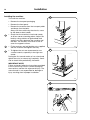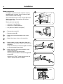
1
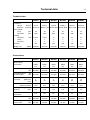
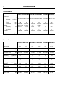
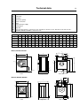
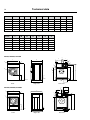
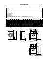
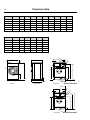
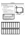
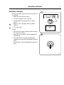
Installation manual W475H/N/S, W485N/S, W4105H/N/S, W4130H/N/S, W4180H/N/S, W4240H/N/S, W4250N/S, W4300H, W4330N/S Compass Control 438 9037-38/US 09.38 Safety and warning signs 3 SAFETY AND WARNINGS SIGNS Replace If Missing Or Illegible One or more of these signs must be affixed on each machine as indicated, when not included as part of the front instruction panel. LOCATED ON THE OPERATING INSTRUCTION SIGN OF THE MACHINE: CAUTION 1. Do not attempt to open door unitl "Door unlocked" indicator is lit. 2. Machine must not be used by children. 3. Do not use flammable liquids in this machine. MACHINE MUST NOT BE USED BY CHILDREN WARNING: ALL OPERATING AND MAINTENANCE PROCEDURES SHOWN ON THE NEXT PAGE OF THIS MANUAL MUST BE FOLLOWED DAILY FOR PROPER OPERATION OF YOUR MACHINE. PLEASE ENTER THE FOLLOWING INFORMATION AS IT APPEARS ON THE MACHINE(S) DATA PLATE(S). MACHINE TYPE OR MODEL MACHINE SERIAL NUMBER(S) ELECTRICAL CHARACTERISTICS:__________ VOLTS,_ ________ PHASE,_________ HZ. MAKE CERTAIN TO KEEP THIS MANUAL IN A SECURE PLACE FOR FUTURE REFERENCE. Safety and warning signs 4 IMPORTANT SAFETY INSTRUCTIONS WARNING To reduce the risk of fire, electric chock, or injury to persons when using your appliance: 1. Read all instructions before using the appliance. 2. This machine must be securely bolted to the floor according to the installation instructions. 3. This machine MUST be serviced and operated in compliance with manufacturers instructions. CHECK DOOR LOCKS EVERY DAY FOR PROPER OPERATION TO PREVENT INJURY OR DAMAGE. IF THE DOOR LOCK FAILS TO OPERATE PROPERLY, PLACE THE MACHINE OUT OF ORDER UNTIL THE PROBLEM IS CORRECTED. 4. Do not wash articles that have been previously cleaned in, washed in, soaked in, or spotted with gasoline, drycleaning solvents, or other flammable or explosive substances, as they give off vapors that could ignite or explode. 5. Do not add gasoline, dry-cleaning solvents, or other flammable or explosive substances to the wash water. These substances give off vapours that could ignite or explode. 6. Under certain conditions, hydrogen gas may be produced in a hot-water system that has not been used for 2 weeks or more. HYDROGEN GAS IS EXPLOSIVE. If the hot-water system has not been used for such a period, before using a washing machine, turn on all hot-water faucets and let the water flow from each for several minutes. This will release any accumulated hydrogen gas. As the gas is flammable, do not smoke or use an open flame during this time. 7. Do not allow children to play on or in the appliance. Close supervision of children is necessary when the appliance is used near children. 8. Before the appliance is removed from service or discarded, remove the door. 9. Do not reach into the appliance if the tube is moving. 10. Do not install or store this appliance where it will be exposed to the weather. 11. Do not tamper with controls. 12. Do not repair or replace any part of the appleance or attempt any servicing unless specifically recommanded in the user-maintenance instructions or in published user-repair instructions that you understand and have the skills to carry out. Safety and warning signs NOTICE TO: OWNERS, OPERATORS AND DEALERS IMPROPER INSTALLATION AND INADEQUATE MAINTENANCE, POOR HOUSEKEEPING AND WILLFUL NEGLECT OR BYPASSING OF SAFETY DEVICES MAY RESULT IN SERIOUS ACCIDENTS OR INJURY. TO ASSURE THE SAFETY OF CUSTOMERS AND/OR OPERATORS OF YOUR MACHINE, THE FOLLOWING MAINTENANCE CHECKS MUST BE PERFORMED ON A DAILY BASIS. 1. Prior to operation of the machine, check to make certain that all operating instructions and warning signs are affixed to the machine and legible. Missing or illegible ones must be replaced immediately. Be sure you have spare signs and labels available at all times. These can be obtained from your dealer. 2. Check the door safety interlock, as follows: (a) OPEN THE DOOR of the machine and attempt to start in the normal manner: For coin-operated models, insert the proper coins to start the machine. For manually operated models, place the ON-OFF switch in the ON position and press the Start switch. THE MACHINE(S) MUST NOT START ! (b) CLOSE THE DOOR to start machine operation and, while it is operating, attempt to open the door without exerting extreme force on the door handle. The door should remain locked! If the machine can start with the door open, or can continue to operate with the door unlocked, the door interlock is no longer operating properly. The machine must be placed out of order and the interlock immediately replaced. (See the door interlock section of the manual.) 3. DO NOT UNDER ANY CIRCUMSTANCES ATTEMPT TO BYPASS OR REWIRE ANY OF THE MACHINE SAFETY DEVICES AS THIS CAN RESULT IN SERIOUS ACCIDENTS. 4. Be sure to keep the machine(s) in proper working order: Follow all maintenance and safety procedures. Further information regarding machine safety, service and parts can be obtained from your dealer. All requests for assistance must include the model, serial number and electrical characteristics as they appear on the machine identification plate. Insert this infor mation in the space provided on the previous page of this manual. 5. WARNING: DO NOT OPERATE MACHINE(S) WITH SAFETY DEVICES BYPASSED, REWIRED OR INOPERATIVE! DO NOT OPEN MACHINE DOOR UNTIL DRUM HAS STOPPED ROTATING! 5 6 Safety and warning signs NOTICE TO INSTALLER Improper installation of this machine: •May cause serious damage to the machine. •May result in other property damage. •May cause personal injury. •Will void the manufacturer's warranty. Improper fastening of this machine to its foundation, inferior foundation materials, an undersized foundation, the use of fabricated steel bases not provided by Electrolux or its approved supplier(s), the use of an improper type, number, or size of mounting bolts, or failure to use proper hardware on mounting bolts may result in damage to the machine that will not be covered by the manufacturer's warranty. Use of a steel base beneath this machine DRAMATICALLY INCREASES the mechanical stress placed on the underlying concrete floor or foundation. This must be taken into consideration when employing a steel base to raise the height of the machine. The use of steel bases more than six inches in height is NOT recommended. If installation requires a base higher than six inches, contact Electrolux Technical Support for advice. Connection to line Voltage or over-current protection devices other than those specified on the data plate may result in severe damage to machine components, and will void the manufacturer's warranty. Refer to complete installation instructions provided in manuals accompanying the machine. Contact Electrolux Technical Support with any questions BEFORE installing this machine. Damage resulting from inadequate installation materials or improper installation techniques will void the manufacturer's warranty. Contents Contents Safety precautions......................................................................................9 Technical data...........................................................................................11 Installation W475H-W4330H.....................................................................19 Transportation and unpacking, W475H, W4105H...............................19 Transportation and unpacking, W4130H-W4300H..............................20 Siting and floor.....................................................................................21 Mechanical installation.........................................................................22 Installation W485N/S-W4330N/S..............................................................23 Siting....................................................................................................23 Floor.....................................................................................................23 Casting a plinth....................................................................................24 Installing the machine..........................................................................26 Water connections...............................................................................27 Drain connection..................................................................................29 Steam connection................................................................................30 Connection of external liquid supplies.................................................31 Functions for I/O-cards........................................................................34 Electrical installation.............................................................................35 Function checks........................................................................................41 The manufacturer reserves the right to make changes to design, material and/or specifications without notice. 7 Safety Precautions Safety Precautions The machine is designed for water washing only. The machine must not be used by children. All installation operations are to be carried out by qualified personnel. Licensed personnel are necessary for all electric power wiring and plumbing Do not hose down the machine with water. The door interlock must be checked daily for proper operation and must not be bypased. All seepage in the system, due to faulty gaskets etc., must be repaired immediately. All service personnel must be fully familiar with the operating manual before attempting any repair or maintenance of the machine The machine must not be sprayed with water Do not add flammable or explosive substances to the wash water. There may give off vapors that could ignite or explode The machine is not intended to be used by people (including minors) with reduced physical or mental capacity or lack of experience and knowledge. Such people must be instructed in the use of the machine by a person who has responsibility for their safety. Minors must be supervised to ensure that they do not play with the machine. All external equipment which is connected to the machine must be CE/EMC-approved and connected using an approved shielded cable. 9 Technical data 11 Technical data W475H Innerdrum volume diameter W4105H W4130H W4180H W4240H W4300H litres/ft3 75/2.6 105/3.7 130/4.6 180/6.4 240/8.5 300/10.6 mm/inch 520/20 1/2 595/23 7/16 650/25 9/16 725/28 9/16 795/31 5/16 795/31 5/16 Drum speed wash extraction rpm rpm 49 1100 49 1025 49 980 44 930 42 890 42 820 7.5/10 x x 13 x x 18 x x 23 x x 23 x x 350 350 350 350 300 kg/lbs 159/350 201/443 267/588 350/771 400/882 509/1122 W475H W4105H W4130H W4180H W4240H W4300H DN20 3/4" DN20 3/4" DN20 3/4" DN20 3/4" DN20 3/4" Rec. water pressure psi 30-90 kPa 200-600 30-90 200-600 30-90 200-600 30-90 200-600 30-90 200-600 30-90 200-600 psi 8-145 kPa 50-1000 8-145 50-1000 8-145 50-1000 8-145 50-1000 8-145 50-1000 8-145 50-1000 Heating electricity kW 5.4/7.5 steam x hot water x G-factor Weight, net 350 Connections Water valves connection Functioning limits for water valve DN20 3/4" Capacity at 45 psi (300 kPa) gallon/min l/min 5 20 5 20 5 20 8 30 15 60 15 60 Drain valve outer Ø mm/inch 75/3 75/3 75/3 75/3 75/3 75/3 gallon/min l/min 45 170 45 170 45 170 45 170 45 170 45 170 DN15 1/2" DN15 1/2" DN15 1/2" DN15 1/2" DN15 1/2" DN15 1/2" Rec. steam pressure psi 45-90 kPa 300-600 45-90 300-600 45-90 300-600 45-90 300-600 45-90 300-600 45-90 300-600 Functioning limits for psi 8-115 steam valve kPa 50-800 8-115 50-800 8-115 50-800 8-115 50-800 8-115 50-800 8-115 50-800 Draining capacity Steam valve connection Technical data 12 Technical data W485N/S W4105N/S W4130N/S W4180N/S W4250N/S W4330N/S Innerdrum volume diameter 105/3.7 130/4.6 180/6.4 250/8.8 330/11.7 litres/ft3 85/3.0 mm/inch 520/20 1/2 595/23 7/16 595/23 7/16 650/25 9/16 725/28 9/16 795/31 5/16 Drum speed wash extraction 49 rpm rpm 587/830 49 548/776 49 548/776 44 525/742 44 497/702 42 474/671 3.0/6.5/ 7.5/10 x x 3.0/ 7.5/10 x x 4.8/9.3 13 x x 18 x x 23 x x 100/200 100/200 100/200 100/200 100/200 100/200 kg/lbs 135/298 145/320 175/386 228/503 287/633 330/727 2.0/3.0/5.6 Heating electricity kW 5.4/7.5 x steam x hot water G-factor Weight, net Connections W485N/S W4105N/S W4130N/S W4180N/S W4250N/S W4330N/S Water valves connection DN20 3/4" DN20 3/4" DN20 3/4" DN20 3/4" DN20 3/4" DN20 3/4" Rec. water pressure psi 30-90 kPa 200-600 30-90 200-600 30-90 200-600 30-90 200-600 30-90 200-600 30-90 200-600 Functioning limits for water valve psi 8-145 kPa 50-1000 8-145 50-1000 8-145 50-1000 8-145 50-1000 8-145 50-1000 8-145 50-1000 Capacity at 45 psi (300 kPa) gallon/min l/min 5 20 5 20 5 20 8 30 15 60 15 60 Drain valve inch outer Ø mm 3 75 3 75 3 75 3 75 3 75 3 75 gallon/min l/min 45 170 45 170 45 170 45 170 45 170 45 170 DN15 1/2" DN15 1/2" DN15 1/2" DN15 1/2" DN15 1/2" DN15 1/2" Rec. steam pressure psi 45-90 kPa 300-600 45-90 300-600 45-90 300-600 45-90 300-600 45-90 300-600 45-90 300-600 Functioning limits for psi 8-115 steam valve kPa 50-800 8-115 50-800 8-115 50-800 8-115 50-800 8-115 50-800 8-115 50-800 Draining capacity Steam valve connection Technical data 1 2 3 4 5 6 7 8 9 10 13 Electrical connection Cold water Hot water Hard water (option) Steam connection Drain Liquid detergent supply Control panel Soap box Door opening, W475H: ø 310 mm/12 3/16", W4105H: ø 365 mm/14 3/8", W4130H: ø 395 mm/15 9/16", W4180H, W4240H, W4300H: ø 435 mm/17 1/8" A B C D E F G H I K L M N O P R S W475H 720 690 1115 355 720 825 45 1030 220 1010 135 910 830 360 100 240 – W4105H 830 705 1300 365 740 910 45 1115 220 1095 135 995 910 415 100 295 – W4130H 910 785 1325 435 825 1035 125 1245 215 1225 300 1125 100 305 455 W4180H 970 870 1410 470 945 1120 115 1330 230 1290 315 1205 370 410 100 335 485 – – W4240H 1020 915 1445 500 955 1155 100 1360 215 1320 300 1240 350 360 100 360 510 W4300H 1020 1060 1445 500 1135 1155 100 1360 215 1320 300 380 335 – – 100 360 W475H, W4105H, W4130H 3 O B A 8 9 I G L 2 4 7 1 10 5 C F 6 D P 5282 B 5281 B 6 E Front Right side 5283 B R Rear side M W4180H, W4240H, W4300H 2 2 L S 9 K M N A B 8 G I 3 7 5 1 10 C K F 6 D 5379 A 5377 A E Front H Right side P 6 Rear side R 5378 A Technical data 14 in inch A W475H 28 3/8 B C 27 3/16 43 7/8 D E F G H I K 14 28 3/8 32 1/2 1 3/4 40 9/16 8 11/16 1 3/4 43 7/8 39 3/4 W4105H 32 11/16 27 3/4 51 3/16 14 3/8 W4130H 35 13/16 30 7/8 52 3/16 17 1/8 32 1/2 40 3/4 4 15/16 49 W4180H 38 3/16 18 1/2 37 3/16 44 1/8 4 1/2 52 3/8 9 1/16 50 13/16 W4240H 40 3/16 56 7/8 19 11/16 37 5/8 45 1/2 3 15/16 53 9/16 8 7/16 51 15/16 W4300H 40 3/16 41 3/4 56 7/8 19 11/16 44 11/16 45 1/2 3 5/16 53 9/16 8 7/16 51 15/16 in inch L W475H W4105H W4130H 34 1/4 55 1/2 36 M N P R S 5 5/16 35 13/1632 11/16 14 3/16 3 5/16 9 7/16 – 5 5/16 12 3/8 O 39 3/16 35 13/16 16 5/16 11 13/16 44 5/16 W4180H 29 1/8 35 13/16 – 47 7/16 14 9/16 3 5/16 11 5/8 – – 3 5/16 12 17 15/16 16 1/8 3 5/16 13 3/16 19 1/8 W4240H 11 13/16 48 13/16 13 3/4 14 15/16 3 5/16 W4300H 12 3/16 14 15/16 – – 8 11/16 43 5/16 8 7/16 48 1/4 14 3/16 20 1/16 3 15/16 14 3/16 13 3/16 W475H, W4105H, W4130H 3 O B A 8 9 I G L 2 4 7 1 10 5 C F 6 D P 5282 B 5281 B 6 E Right side Front 5283 B R Rear side M W4180H, W4240H, W4300H 2 2 L S 9 K M N A B 8 G I 3 7 5 1 10 C K F 6 D 5379 A 5377 A E Front H Right side P 6 Rear side R 5378 A Technical data 1 2 3 4 5 6 7 8 9 10 15 Electrical connection Cold water Hot water Steam connection Drain Liquid detergent supply Control panel Soap box Water reuse Door opening, W485S: ø 310 mm/12 3/16", W4105S, W4130S: ø 365 mm/14 3/8", W4180S: ø 395 mm/15 9/16", W4250S, W4330S: ø 435 mm/17 1/8" A W485N/S 660 B C D E F 730 1115 355 765 825 G H I K L 45 1030 215 1010 130 M N O P R 830 385 - 100 225 W4105N/S 720 705 1200 365 740 910 45 1115 215 1095 130 910 420 - 100 235 W4130N/S 720 790 1200 365 825 910 45 1115 215 1095 130 910 420 - 100 235 W4180N/S 750 880 1325 435 915 1035 45 1245 130 1225 210 1040 325 295 100 225 W4250N/S 830 955 1410 470 990 1120 45 1330 160 1290 245 1125 325 325 100 265 W4330N/S 910 1040 1445 500 1075 1155 45 1365 160 1325 245 1155 280 325 100 210 3 A N B 7 8 I G L 2 9 6 1 10 4 C 5 D P 5281 E Front H K M F 5 5282 Right side 5283 R W485N/S-W4130N/S Rear side O N 3 L I G 2 9 6 4 1 K H M F P 5 Rear side R 5459 W4180N/S-W4330N/S Technical data 16 in inch A B C D E F G H I K 30 1/8 32 1/2 W485N/S 26 28 3/4 43 7/8 14 1 3/4 40 9/16 8 7/16 39 3/4 W4105N/S 28 3/8 27 3/4 47 1/4 14 3/8 29 1/8 35 13/16 1 3/4 40 7/8 8 7/16 43 1/8 W4130N/S 28 3/8 31 1/8 47 1/4 14 3/8 32 1/2 35 13/16 1 3/4 40 7/8 8 7/16 43 1/8 W4180N/S 29 1/2 32 11/16 52 3/16 17 1/8 36 40 3/4 1 3/4 49 5 1/8 48 1/4 W4250N/S 32 11/16 37 5/8 55 1/2 17 1/8 39 44 1/8 1 3/4 52 3/8 6 5/16 50 13/16 45 1/2 1 3/4 53 3/4 6 5/16 W4330N/S 35 13/16 40 15/16 56 7/8 19 11/16 42 5/16 in inch L M N O P R W485N/S 5 1/8 32 11/16 15 3/16 – 3 15/16 8 7/8 W4105N/S 5 1/8 35 13/16 19 9/16 – 3 15/16 9 1/4 W4130N/S 5 1/8 35 13/16 16 9/16 – 3 15/16 9 1/4 W4180N/S 8 1/4 40 15/1612 13/16 11 5/8 3 15/16 8 7/8 W4250N/S 9 5/8 44 5/16 12 13/16 12 13/16 3 15/16 10 7/16 W4330N/S 9 5/8 45 1/2 11 12 13/16 3 15/16 52 3/16 8 1/4 3 A N B 7 8 I G L 2 9 6 1 10 4 C 5 D P 5281 E Front H K M F 5 5282 Right side 5283 R W485N/S-W4130N/S Rear side O N 3 L I G 2 9 6 4 1 K H M F P 5 Rear side R 5459 W4180N/S-W4330N/S Technical data W475H 17 W4105H W4130H W4180H W4240H W4300H 17.1 16.3 15.5 14.8 13.7 560±112 2.5±0.5 703±114 3.1±0.5 944±221 4.2±1.0 1158±221 5.2±1.0 1387±277 6.2±1.2 W485N/S W4105N/S W4130N/S W4180N/S W4250N/S W4330N/S Hz 9.3/13.8 8.7/12.9 8.7/12.9 8.3/12.3 7.9/11.7 7.5/11.2 Max floor load at extraction kN 1.7 ± 3.1/ 1.7 ± 2.6 2.1 ± 3.6/ 2.1 ± 3.0 2.3 ± 4.1/ 2.3 ± 3.7 2.9 ± 4.7/ 2.9 ± 4.6 3.7 ± 5.3/ 3.7 ± 5.8 4.5 ± 5.8/ 4.5 ± 6.8 lbs force 375±696/ 375±583 468±813/ 468±675 518±912/ 518±824 648±1057/ 648±1038 842±1189/ 1019±1310/ 842±1301 1019±1524 Frequency of the dynamic force Hz 18.3 Max floor load lbs force 417±110 at extraction kN 1.9±0.5 Frequency of the dynamic force Installation Installation W475H-W4330H 19 1 Transportation and unpacking, W475H, W4105H The machine is delivered complete with expansion bolts etc. packed inside the machine in the drum. The machine is delivered bolted onto the transport pallet and packed in a crate or box. • Remove packing from the machine. • Remove front and rear panel. Remove the bolts between the machine and pallet. • Mount front and rear panel. • Mount the feet. • Place the machine on its final position. • Level the machine with the feet of the machine. 1 5325 2 The machine also comes with transport safety devices (four plate angles between the frame and the drum). In order to remove the safety devices: • Unpack the machine. 2 • Remove front and rear panel. • Remove both front metal angels. • Remove both rear metal angels. NOTE! Once the shipping safety devices have been removed, handle the machine carefully to avoid damage to the suspension components. 5326 Installation 20 Transportation and unpacking, W4130H, W4180H, W4240H, W4300H 3 The machine is delivered complete with expansion bolts etc. packed inside the machine in the drum. The machine is delivered bolted onto the transport pallet and packed in a crate or box. • Remove packing from the machine. • Remove front and rear panel. Remove the bolts between the machine and pallet. • Mount front and rear panel. • Mount the feet. 4 NOTE! Regarding W4300H note the positioning of the two front feet. • Place the machine on its final position. 5340 4 • Level the machine with the feet of the machine. 3 The machine also comes with transport safety devices (two plate angles between the support and the drum). In order to remove the safety devices: • Unpack the machine. 5 • Remove the two side panels. • Remove the two transport securities. NOTE! Once the shipping safety devices have been removed, handle the machine carefully to avoid damage to the suspension components. 6445 5 5341 Installation Siting and floor Install the machine close to a floor drain or open drain. 6 21 6 In order to make installation and servicing the machine easier the following clearances are recommended: • At least 20 inches (500 mm) between the machine and the wall behind • and min. 2 inches (50 mm) on both sides of the machine whether installed next to the wall or other machines. 500 mm 50 mm 2" 20" 5327 Installation 22 Mechanical installation 7 7 • Mark and drill 2 holes (ø 8 mm/5/16") about 40 mm/1 9/16" deep (W475H-W4105H) and ø 10 mm/3/8" and 50 mm/2" deep (W4130HW4300H) in the positions. = position of feet = drilling points for expander bolts A C D B • The machine must be lifted in its base frame. • Place the machine over the two drilled holes on the foundation. H G • Check that the machine is in level, both sideto-side and front to back. Adjust with the feet. F E Front It is of utmost importance that the machine level, from side to side as well as front to rear. If the machine is not properly leveled, it may result in out-of-balance without a real out of balance in the drum. • Insert the expansion bolts supplied in the holes drilled in the floor. Fit the washers and nuts, and tighten securely. in mm A B C D E F G H W475H 495 460 110 130 375 170 40 100 W4105H 575 465 130 140 455 185 35 95 W4130H 635 490 135 175 515 195 60 110 W4180H 715 545 125 205 595 185 60 115 W4240H 790 615 115 180 670 175 60 115 W4300H 790 755 60 180 670 175 60 75 B C D E F G H in inch A W475H 19 1/2 18 1/8 4 5/16 5 1/8 W4105H 22 5/8 18 5/16 5 1/8 5 1/2 17 15/16 7 5/16 1 3/8 3 3/4 W4130H 6 7/8 20 1/4 7 11/16 2 3/8 4 5/16 W4180H 28 1/8 21 7/16 4 15/16 8 1/16 23 7/16 7 5/16 2 3/8 4 1/2 W4240H 31 1/8 24 3/16 4 1/2 7 1/16 26 3/8 6 7/8 2 3/8 4 1/2 W4300H 31 1/8 29 5/8 7 1/16 26 3/8 6 7/8 2 3/8 2 15/16 25 19 5/16 5 5/16 2 3/8 14 3/4 6 11/16 1 9/16 3 15/16 5358 Installation Installation W485N/S-W4330N/S 23 8 Leave the machine on the transport pallet until it can be placed in the final, prepared position. Siting Install the machine close to a floor drain or open drain. In order to make installation and servicing the machine easier the following clearances are recommended: 8 • At least 20 inches (500 mm) between the machine and the wall behind. • Minimum 1 inch (25 mm) to next machine if more than one machine is installed on a foundation. Floor In this type of machine, the drum is attached di rectly to the frame. As a result the floor under the machine must be stable enough to absorb the dynamic forces generated during spin cycles. For that reason, the mounting bolts must be cast into the floor material itself. The machine must be securely fastened to a suitable foundation using M16 (5/8 inch) threaded rod, flat washers and lock nuts or lock washers. Failure to properly secure the machine to its foundation, or securing the machine to an inadequate foundation, will result in severe vibration, damage to the machine, and will void the manufacturer´s warranty. When fixing the machine to an existing cement floor, it must be at least 8 inches (200 mm) thick. The floor must be able to withstand the loads in dicated in the table. If it isn’t possible to cast the bolts into the floor, an alternative might be to use so-called chemical anchors. Your local dealer can provide the infor mation you need. IMPORTANT NOTE: The use of chemical anchors and/or the use of a fabricated steel mounting base DOES NOT reduse the thickness requirement for the underlying concrete floor. The floor MUST BE AT LEAST 8 INCHES (200 MM) THICK, or a new concrete foundation MUST be poured. 5327 Installation 24 Casting a plinth 9 9 A foundation should be used where the existing floor is less than 8 inches (200 mm) thick or in order to ensure that the machine is securely anchored and will not vibrate excessively. The foundation must be at least 8 inches (200 mm) thick. Proceed as follows: 10 • Break up the existing floor to a depth of ap prox. 5 inches (125 mm) and check that the sides of the hole are tapered outward so that the longest side at the bottom measures 5 inches (125 mm) more than at the top. 150-200 mm • Make the forms for the foundation. • Moisten the hole well and apply cement to the sides and bottom. 40 mm 5462 10 • A number of mounting bolts must be set into the concrete of the foundation. The bolts need to project 1-1 1/2 inches (40 mm) out of the base. Pour the concrete into the prepared base mold and make sure that the surface is level. • The concrete should be left to set for at least two days before mounting the machine on the foundation. • Mounting bolt locations are shown with respect to the outer surface of the machin's front panel. If the front panel is to be set back from the front of the foundation, add the setback distance to dimension "E". 0899 Installation Model W4330S 11 For this machine two expander bolts shall be mounted at the front part of the machine. 11 25 B • Drill two holes (1) ø10 mm/ 3/8" and 40 mm/ 1 9/16" deep. • After the machine has been placed over the other four bolts, place the two spacer washers over the two holes. They shall be placed between the machine and foundation. A F D I E • Mount the expenderbolts in the drilled holes and fasten the machine. Don´t forget the washers. 1 = G C H = 1 6099 in mm A B W485N 725 660 W4105N 700 720 W4130N 785 720 W4180N 875 750 W4250N 950 830 W4330N 1035 910 W485S 725 660 W4105S 700 720 W4130S 785 720 W4180S 875 750 W4250S 950 830 W4330S 1035 910 in inch A W485N 28 9/16 W4105N 27 7/8 W4130N 30 7/8 W4180N 34 7/16 W4250N 37 3/8 W4330N 40 3/4 W485S 28 9/16 W4105S 27 7/8 W4130S 30 7/8 W4180S 34 7/16 W4250S 37 3/8 W4330S 40 3/4 C 495 575 575 635 715 790 495 575 575 635 715 790 D 445 385 495 570 635 695 445 385 495 570 635 695 E F G 115 665 – 120 695 – 120 760 – 120 855 – 125 955 – 1351050810 115 665 495 120 695 595 120 760 595 120 855 655 125 955 735 1351050810 B C 26 19 1/2 28 3/8 22 3/4 28 3/8 22 5/8 29 1/2 25 32 11/16 28 1/8 35 13/16 31 1/8 26 19 1/2 28 3/8 22 3/4 28 3/8 22 5/8 29 1/2 25 32 11/16 28 1/8 35 13/16 31 1/8 D 17 1/2 15 3/16 19 1/2 22 7/16 25 27 3/8 17 1/2 15 3/16 19 1/2 22 7/16 25 27 3/8 H – – – – – 10 0 10 10 10 10 10 I – – – – – 95 75 80 80 85 85 95 E F G 4 1/2 26 3/16 – 4 3/4 27 13/32 – 4 3/4 29 15/16 – 4 3/4 33 11/16 – 4 15/16 37 5/8 – 5 5/16 41 5/16 31 7/8 4 1/2 26 3/16 19 1/2 4 3/4 27 13/32 23 7/16 4 3/4 29 15/16 23 7/16 4 3/4 33 11/1625 13/16 4 15/16 37 5/8 28 15/16 5 5/16 41 5/16 31 7/8 H I – – – – – – – – – – 13/32 3 3/4 0 2 15/16 13/32 3 1/8 13/32 3 1/8 13/32 3 3/8 13/32 3 3/8 13/32 3 3/4 Installation 26 Installing the machine To install the machine: • Remove the transport packaging • Remove the front panel. • Remove the machine from the transport pallet and locate it on the bolts. Always lift the machine by the chassis, never by the door or door handle. 12 • Check that the machine is level and steady at all four corner mounting points. Adjust the level by using stainless or galvanized steel washers or shims between the machine and the floor. The washers must be of a size to cover the support surface. 13 • Fit the washers and self-locking nuts supplied with the machine and tighten securely. 14 • To tighten the nuts we recommend to use a rachet wrench, especially in the right rear corner. 12 5463 13 During the first several weeks of use, check and tighten the nuts (as necessary) frequently. Continue to check them periodically, thereafter. IMPORTANT NOTE: Failure to closely follow the instructions provided in this manual may result in severe damage to the machine, and the risk of personal injury. The manufacturer is not responsible for damage or injury resulting from improper installation. 5464 14 5951, 5952 Installation Water connections All inlet connections to the machine are to be fitted with manual shut-off valves and filters, to facilitate installation and servicing. Water pipes and hoses should be flushed clean before installation. After installation, hoses should hang in gentle arcs. Hoses are to be of an approved type and grade, to comply with national regulations. The machine may have between one and four DN 20 (R 3/4") water connectors. All connectors present on the machine must be connected to the water supply, or the machine may not function properly. The table shows the possible connection options, which will depend on the model of the machine. All water connectors must be connected up, otherwise the wash program will not function correctly. The water pressure data is as follows: • min: 15 PSI (100 kPa) • max: 90 PSI (600 kPa) • recommended: 30-90 PSI (200-600 kPa) If the water pressure is below the min. value, the wash result can not be guaranteed for certain program. 27 Installation 28 Water type 15 cold and hot Water connection 1 2 3 2 cold hot 16 cold and hot cold hot cold*/ hot * For detergent container. Extra water valve which can be used for hard water if soft water is connected to 1. This valve can also be used for water reuse from tank. If pump is used, it is only a water connection without valve. 15 W475H, W4105H, W4130H W485N/S, W4105N/S W4130N/S 1 5328 16 2 W4180H, W4240H, W4300H, W4180N/S, W4250N/S W4330N/S 1 3 5339 Installation Drain connection Connect a 3 inch O.D. (75 mm) pipe or rubber hose to the machine’s drain pipe, ensuring a downward flow from the machine. Avoid sharp bends which may prevent proper draining. 17 The washer may drain in to a drainage through or into a closed drain system. In either case, be sure to comply with all applicable national and local plumbing code provisions. 29 17 5330 Installation 30 Steam connection 18 Inlet pipes connected to the machine must be equipped with a manual shut-off valve to facilitate installation and servicing. The connection hose must be of type ISO/13071983 or equivalent. Connection size at filter: DN 15 (BSP 1/2"). Steam pressure required: • minimum: 7 psi (50 kPa) • maximum: 115 psi (800 kPa) A B 6600 19 • rec. pressure: 600 kPa (6 kp/cm ) 2 18 • Remove top cover (A). • Remove casing (B). 19 20 21 22 • Mount the articulated nipple to the steam valve. 5862 • Mount the steam valve on the machine. 20 • Mount nipple, strainer and elbow. Note the direction of the strainer. Mount steam hose to the elbow. Check that there are no sharp angles or bends on the connected steam hose. • Mount the hose with wires between steam valve and machine. Connect wires in the steam valve. Connect ground cable to the terminal ground connection. 6601 21 Connect the ”HEAT” cable connector to the ”HEAT” terminal on the I/O board. 6602 22 "HEAT" 6604 Installation Connection of external liquid supplies 31 23 1 The external dosing equipment power supply must never be connected to the machine’s incoming terminal block. A 3 4 B Machines fitted with connectors 23 • Connect the pump equipment to connections A and B on the washing machine. Connect the signal cable to B and the power supply to A. 24 2 1 3 6 4 9 5 Machines without connectors • Connect the external pump equipment for liquid washing detergent to the I/O board, which is located to the right of the incoming power supply. The I/O card has edge connectors for connecting external pumps. 2 1=N 2=L 4 = Ground 7 1=N 2 = Program run 3 = Signal 1 4 = Signal 2 5 = Signal 3 6 = Signal 4 7 = Signal 5 6598 24 • Edge connectors on the I/O board can be loosened for connecting cables. 11 = N 18 = Program run 12 = Signal 1 13 = Signal 2 14 = Signal 3 15 = Signal 4 16 = Signal 5 6572 Installation 32 Outputs 25 26 • Connect external power supply (e.g. 24V DC) for pumps to 9 and 10. If an internal power supply (from the washing machine) is being used, it can be taken from 1 (N) and connected to 9 and from 2 (L) and connected to 10. Max load on the outputs 0.5 A. • Signals for pumps 1-5 are connected to 12-16 where connector 12 Washing detergent signal 1 13 Washing detergent signal 2 14 Washing detergent signal 3 15 Washing detergent signal 4 16 Washing detergent signal 5 25 Inputs • The signal level can be 5-24V DC/AC or 100240V AC. For 5-24V, the signal reference is connected to 3 and for 100-240V to 4. Potentials on the inputs cannot be mixed. NB! The I/O board will be damaged if the voltage on connection 3 is too high, >24V. 6634, 6635 26 6236 Installation 27 33 • Connection 8 may be connected if the washing program is to pause, e.g. while washing detergent is being dosed. The figure shows an example of engaging a 24V pause signal. The washing program will pause for as long as the pause signal remains activated (high). 27 Dosing system 3 0V Pause signal 24V 8 24V DC 6266 28 Detergent tank 1 2 230V Empty 4 7 6265 28 29 • Connection 7. If this is connected, an error message will be displayed indicating that one of the chemical tanks is empty. The washing program will continue, however. The figure shows an example of engaging a normal open contact. 29 A • Connect the liquid dosing hoses to any of the connections marked A. 6577 Installation 34 Functions for I/O -cards • Check the electrical schematic for the machine to find out what functions are available for the machine. 22E 6315 • Heating pause: Signal can be connected to connection 6 to pause the machine whilst it heats up. The machine’s heating program will pause for as long as the pause signal remains activated (high). Installation Electrical installation Electrical installation must be carried out by licensed, qualified personnel! Machines with frequency-controlled motors can be incompatible with certain types of earth leakage circuit breakers. It is important to know that the machines are designed to provide a high level of personal safety, which is why items such as ground-fault interrupting circuit breakers are not necessary. If you still want to connect your machine across ground fault circuit breaker, please remember the following: • contact a licensed, qualified electrician to ensure that the appro priate type of breaker is chosen and that the breaker rating is correct • for maximum reliability, connect only one machine per circuit breaker • it is important that the earth wire is properly connected, including to the ground fault circuit breaker. An individual electrical disconnect must be provided in proximity to each machine. The connecting cable should hang in a gentle curve. For proper circuit breaker sizes, see table on the next page. 35 Installation 36 Single-phase connection: 30 Connect the earth and other two wires as shown in example ”1AC” in the figure. 30 Three-phase connection: 31 Connect the earth and the three phases as shown in example ”3AC” in the figure. When the installation is completed, check: • that the drum is empty. • that the machine operates by turning on the mains switch, starting the machine and using RAPID ADVANCE to reach the spin cycle (see operations manual). 1AC 6524 IMPORTANT When making power supply connections to machines rated 208-240V AC, do not connect any phase measuring in excess of 125 V AC (with respect to earth ground) to the L1 or L2 terminals on the connection block. So-called "stinger legs" must be connected to the "L3" terminal, which does not feed power to the control circuits of the machine. On three-phase models (except W4330S), check that the drum rotates in the direction indicated on the machine while in extraction. If the direction is incorrect, reverse two of the power line phases to correct the rotation direction, while observing the note above. 31 3AC 6525 Installation 37 W475H Heating alternative Voltage alternative Total kW No heating 100-120 V 1 AC 1.1 or Steam208-240 V 1 AC 1.1 heating El heating 220-230 V 3 AC 7.0 Fuse A 15 10 20 W4105H Heating alternative Voltage alternative Total kW No heating 208-240 V 1 AC 1.3 or Steam heating heating 208-240 V 3 AC 9.2 El Fuse A 15 30 W4130H Heating alternative Voltage alternative Total kW Fuse A No heating 208-240 V 1 AC 1.6 Steam or heating 15 heating El 66 35 20 208-240 V 1 AC 208-240 V 3 AC 440/480 V 3 AC 12.5 11.8 13.5 Installation 38 W4180H Heating alternative Voltage alternative Total kW heating 208-240 V 1 AC 2.3 No Steam or heating heating 208-240 V 3 AC 17.5 El Fuse A 15 60 W4240H Heating alternative Voltage alternative Total kW heating 208-240 V 1 AC 2.6 No Steam or heating heating 208-240 V 3 AC 18.3 El Fuse A 15 63 W4300H Heating alternative Voltage alternative Total kW No heating 208-240 V 1 AC 2.1 Steam or heating heating 208-240 V 3 AC 20.9 El Fuse A 15 60 Installation 39 W485N/S Heating alternative Voltage alternative Total kW No heating 120 V 1 AC 0.5 or Steam208-240 V 1 AC 0.5 heating El heating 208-240 V 3 AC 7.3 Fuse A 15 15 30 W4105N/S Heating alternative Voltage alternative Total kW heating 120 V 1 AC 0.75 No Steam208-240 V 1 AC 0.75 or heating heating 208-240 V 3 AC 9.2 El Fuse A 15 15 30 W4130N/S Heating alternative Voltage alternative Total kW No heating 120 V 1 AC 0.8 Steam208-240 V 1 AC 0.8 or heating heating 208-240 V 3 AC 9.3 El Fuse A 15 15 30 Installation 40 W4180N/S Heating alternative Voltage alternative Total kW heating 120 V 1 AC 1 No Steam208-240 V 1 AC 1 or heating heating 208-240 V 1 AC 12.1 El 208-240 V 3 AC 12.7 Fuse A 15 15 60 50 W4250N/S Heating alternative Voltage alternative Total kW Fuse A heating 120 V 1 AC 1.4 No Steam208-240 V 1 AC 1.4 or heating 20 15 heating El 208-240 V 3 AC 12.1 60 Voltage alternative Total kW Fuse A W4330N/S Heating alternative No heating 120 V 1 AC 1.6 Steam208-240 V 1 AC 1.6 or heating heating 208-230 V 3 AC 19.7 El 20 15 60 Function checks Function checks 41 1 Perform the following checks once the machine is installed: • Open the manual water valves. • Turn on the power to the machine. • Put detergent into compartment 2 (Main wash). 1 • Select a "HOT" program with the control knob (1). 2 • Press the knob. 1 HOT Check: • that the drum rotates normally and that there are no unusual noises. • that there are no leaks in water supply/drain connections. 6217, 6179, 6204 2 • that water passes through the detergent compartment and fabric conditioner compartment. • that the door cannot be opened during a program. 6180 www.electrolux.com/laundrysystems Share more of our thinking at www.electrolux.com