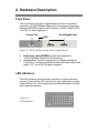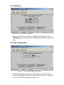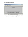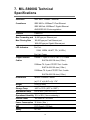
1
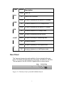
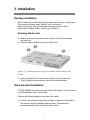
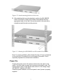
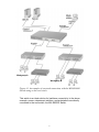
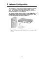
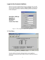
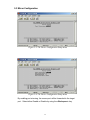
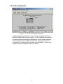
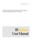
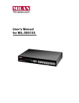
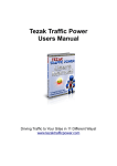
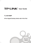
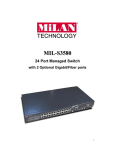
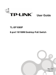
8-Port Gigabit Switch MIL-S8000G User Guide Eight Auto-negotiation 10/100/1000Mbps Gigabit Ethernet RJ-45 Ports. Each port with Auto MDI/MDIX. Regulatory Approval - FCC Class A - UL 1950 - CSA C22.2 Number 950 - EN60950 - CE EN55022 Class A EN55024 Canadian EMI Notice This Class A digital apparatus meets all the requirements of the Canadian Interference-Causing Equipment Regulations. Cet appareil numerique de la classe A respecte toutes les exigences du Reglement sur le materiel brouilleur du Canada. European Notice Products with the CE marking comply with both the EMC Directive (89/336EEC) and the Low Voltage Directive (73/23EEC) issued by the commisions of the European Community. Compliance with these directives implies conformity to the following European norms: - EN55022 (CISPR 22) - Radio Frequency Interference - EN61000-X - Electromagnetic Immunity - EN60950 (IEC950) - Product Safety Five-Year Limited Warranty MiLAN Technology warrants to the original consumer or purchaser that each of its product and component thereof, will be free from defects in material and/or workmanship for a period of five years from the original factory shipment date. Any warranty hereunder is extended to the original consumer or purchaser and is not assignable. MiLAN Technology makes no express or implied warranties including, but not limited to, any implied warranty of merchantability or fitness for a particular purpose, except as expressly set forth in this warranty. In no event shall MiLAN Technology be liable for incidental or consequential damages, costs, or expenses arising out of or in connection with the performance of the product delivered hereunder. MiLAN Technology will in no case cover damages arising out of the product being used in a negligent fashion or manner. Trademarks © 2003 MiLAN, the MiLAN logo and MiLAN Technology are either trademarks or registered trademarks of MiLAN Technology in the United States and/or other countries. To Contact MiLAN Technology For prompt response when calling for service information, have the following information ready: - Product serial number and revision - Date of purchase - Vendor or place of purchase You can reach MiLAN Technology technical support at: - E-mail: [email protected] - Telephone: +1.408.744.2751 - Fax: +1.408.744.2771 MiLAN Technology 1329 Moffett Park Drive Sunnyvale, CA 94089 United States of America Telephone: +1.408.744.2775 Fax: +1.408.744.2793 http://www.milan.com [email protected] P/N 90000404_A Table of Contents 1. Introduction Features Package Contents 2. Hardware Description Front Panel LED Indicators Rear Panel 3. Installation Desktop Installation Rack-mount Installation Power On 4. Network Application Backbone Switch 5. Network Configuration Login to the Console Interface 5.1 Port Status 5.2 Port Configuration 5.3 Mirror Configuration 5.4 VLAN Configuration 5.5 VLAN Setup 5.6 Trunk Configuration 5.7 Miscellaneous Configuration 6. Troubleshooting 7. MIL-S8000G Technical Specifications 1 1. Introduction Gigabit Ethernet over copper technology is a cost-effective way for network equipment to be upgraded from Fast Ethernet to Gigabit speeds without the use of expensive fiber optics cabling. Gigabit networks create high-speed backbone connections between switches, servers, databases and end stations. The MIL-S8000G, an 8-Port Gigabit switch, is an ideal solution for solving traffic block at the core of the network. It offers eight auto-negotiation 10/100/1000Base-T Gigabit Ethernet ports that can significantly improve your network’s backbone performance. The switch will fit into any level network to act as an exit to the backbone switch that can handle throughput speeds up to 2000Mbps at Full-duplex mode. Figure 1-1. MIL-S8000G The switch will automatically detect the speed of the device that you plug into it to allow connections to 10, 100 or 1000Mbps devices. The eight port Gigabit switch features automatic MDI/MDIX connections for each port. It also features store-and-forward switching and autolearning of source addresses with an 8,000 entry MAC address table. Features Conforms to IEEE 802.3, 802.3u, 802.3ab and 802.3x standards Eight auto-negotiation 10/100/1000Base-TX switch ports (Using shielded RJ-45 connections) Automatic MDI/MDIX crossover for all ports Embedded 8K entry MAC address table (Supports 8K Unicast/Multicast/Broadcast addresses) Store-and-Forward architecture Full Duplex and Half Duplex flow control support Plug-and-Play configuration LED Indicators for Power, 100M, 1000M, LK/ACT, and FDX/COL Standard 19-inch rackmount design Console Management (Port Configuration/Statistics, Port Mirroring, Port-Based VLAN’s and Port Trunking) 2 Package Contents MIL-S8000G 8 port Gigabit switch Power Cord Four Adhesive Rubber Feet User’s Manual Warranty Card Compare the contents of your MIL-S8000G package with the standard checklist above. If any item is missing or damaged, please contact your local dealer for service. 3 2. Hardware Description Front Panel The Front Panel of the 8-Port Gigabit Switch consists of eight autonegotiation 10/100/1000Mbps Ethernet RJ-45 connectors, supporting automatic MDI/MDIX, and four LED-indicators (1000M, 100M, LK/ACT, FUL/COL) for each Gigabit port. Console Port RJ-45 Gigabit Ports LEDs Figure 2-1. The Front Panel of the 8-Port Gigabit Switch RJ-45 Ports ( Auto MDI/MDIX ): Eight auto-negotiation 10/100/1000Mbps Ethernet RJ-45 connectors. Console Port : Console management is available through the Console Port. A direct connection between the Switch and an end station ( PC ) via a RS-232 cable is required. LED Indicators The LED Indicators gives a real-time indication of system operating statuses. There are four LED-indicators for each Gigabit port and one Power LED for Unit. The following table provides descriptions of LEDs status and their meaning. Figure 2-2. LED Indicators. 4 LED Status Description Green Power On Power Off Power is not connected Green The port is operating at the speed of 1000Mbps. 1000M Off No device attached or in 10/100Mbps mode Green The port is operating at the speed of 100Mbps. 100M Off No device attached or in 10Mbps mode Green The port is connecting with the device. LK/ACT Blinks Off The port is receiving or transmitting data. No device attached. Yellow The port is operating in Full Duplex mode. FD Off No device attached or in Half Duplex mode. Table 2-1. Descriptions of LED Indicators Rear Panel The 3-pronged power plug and ventilation fan are located at the rear panel. The switch will work with AC in the range 100-240V AC, 50-60Hz. The rear panel of the MIL-S8000G Gigabit switch is shown below. Figure 2-3. The Rear Panel of the MIL-S8000G Switch 5 3. Installation Desktop Installation Set the switch on a sufficiently large flat space with a power outlet nearby. The surface should be clean, smooth, level, and sturdy. Make sure there is enough clearance around the switch to allow attachment of cables, power cord and air circulation. Attaching Rubber Feet A. Make sure mounting surface on the bottom of the switch is grease and dust free. B. Remove adhesive backing from the rubber feet. Figure 3-1. Attaching rubber feet to each corner on the bottom of the Switch C. Apply the rubber feet to each corner on the bottom of the switch. These footpads can prevent the switch from shock/vibration. Rack-mounted Installation The MIL-S8000G includes a rack-mounted kit that allows it to be mounted in an EIA standard size, 19-inch Rack. Perform the following steps to rack mount the switch: A. Position one bracket to align with the holes on one side of the switch and secure it with the smaller bracket screws. Then attach the remaining bracket to the other side of the switch. 6 Figure 3-2. Attach mounting brackets with screws B. After attaching both mounting brackets, position the MIL-S8000G switch in the rack by lining up the holes in the brackets with the appropriate holes on the rack. Secure the switch to the rack with a screwdriver and the rack-mounting screws. Figure 3-3. Mounting the MIL-S8000G in an EIA standard 19-inch Rack Note: For proper ventilation, allow at least 4 inches (10 cm) of clearance on the front and 3.4 inches (8 cm) on the back of the switch. This is especially important for enclosed rack installation. Power On Connect the power cord to the power socket on the rear panel of the switch. The other side of power cord connects to the power outlet. The internal power supply in the Switch works with AC in the voltage range 100-240VAC, frequency 50~60Hz. Check the power indicator on the front panel to see if power is properly supplied. 7 4. Network Application The MIL-S8000G Switch can be used connect servers, switches, workstations, and PCs (a Gigabit 1000Base-T NIC is required for PC installation) to each other by connecting these devices directly to the Switch. The Switch automatically learns node addresses, which are used to filter and forward all traffic, based on the destination address. Backbone Switch The MIL-S8000G Switch is an ideal solution for enterprise networks where large data broadcasts are constantly processed. All ports can be connected to departmental switches, and the departmental switches can be connected to the MIL-S8000G Switch. Each end station can access the server’s data by connecting the servers to the core switch. This will allow all the devices in the network to communicate with each other. 8 Workgroup A Workgroup B Figure 4-1. An example of a network connection, with the MIL-S8000G Switch acting as the core switch. This switch is an ideal solution for backbone connectivity. In the above example, servers, department switches, and workstations are directly connected to the core switch, the MIL-S8000G Switch. 9 5. Network Configuration The Console port is a female DB-9 connector that enables a connection to a PC or terminal for monitoring and configuring the MIL-S8000G Switch. Use the supplied RS-232 cable with a male DB-9 connector to connect a terminal or PC to the Console port. The Console configuration allows the switch to be set to enable a user at a remote console terminal to communicate with the MIL-S8000G Switch as if the console terminal were directly connected to it. Figure 5-1. Connecting the MIL-S8000G Switch to a terminal via RS232 cable. 10 Login to the Console Interface When the connection between Switch and PC is finished, turn on the PC and run a terminal emulation program or Hyper Terminal. Configure the communication parameters to match the following default characteristics of the console port: Baud Rate: 9600 bps Data Bits: 8 Parity: none Stop Bit: 1 Control flow: None Figure 5-2. The settings of communication parameters 5.1 Port Status Figure 5-3. The screen of Port Status View the statistics information displayed in this screen regarding a specific port by entering the port number. Refresh or reset the counter as necessary. 11 5.2 Port Configuration Figure 5-4. The Port Configuration menu Select each port to change the status, toggle the Enable / Disable field and enter the appropriate value in the Flow Control field. 12 5.3 Mirror Configuration Figure 5-5. The Device Configuration Setup menu Figure 5-6. The Device Configuration Setup menu By enabling port mirroring, the source port will be forwarded to the target port. Select either Enable or Disable by using the <Backspace> key. 13 5.4 VLAN Configuration Figure 5-7. The VLAN Configuration menu Assigning physical ports within a work group is a simple and common method of defining a virtual work group – VLAN. It delivers the benefit of broadcast control and simplifies configuration for the network manager. One advantage of the Port-Based VLAN is its simplicity and ease of configuration. Limited security, however, is its drawback – anyone can plug into the port and gain access to the VLAN. 14 5.5 VLAN Setup Figure 5-8. The VLAN Setup menu Select the VLAN entry to Enable or Disable the VLAN group. Use the <Backspace> key to Enable (add) or Disable (remove) ports in the VLAN group. 5.6 Trunk Configuration Figure 5-9. The Trunk Configuration menu Multiple links between switches can be grouped or trunked to work as one virtual, aggregate link. Each trunk can hold up to 2 ports. Only ports of the same speed can belong to a single trunk. 15 5.7 Miscellaneous Configuration Figure 5-10. The Misc. Configuration menu Select each port to change the status, toggle the Enable / Disable field and enter the appropriate value in the Aging Time field. 16 6. Troubleshooting This troubleshooting section is intended to help solve many common problems that might occur when installing the MIL-S8000G. The switch can be easily monitored through panel indicators to assist in identifying problems. Power If the power indicator does not light up when the power cord is plugged in, you may have a problem with the power outlet or power cord. However, if the switch powers off after running for awhile, check for loose power connections, power losses or surges at the power outlet. If you still cannot resolve the problem, contact your local dealer for assistance. Diagnostic LED Indicator 1. If the link indicator does not light up after making a connection, check whether the network interface (e.g., a network adapter card on the attached device), network cable, or switch port is defective or not. 2. Verify that the switch and attached device are powered on. 3. Be sure the cable is plugged into both the switch and the corresponding device. 4. Verify that the proper cable type is used and its length does not exceed specified limits (100 meters). Transmission Mode Verify that each port is set to the same transmission mode used by the attached device, for example Half or Full-Duplex. The RJ-45 ports use auto-negotiation to set the transmission mode. If the attached devices do not support auto-negotiation, the switch will assume the port operates at half duplex. Cabling RJ-45 ports: Use unshielded twisted-pair (UTP) or shielded and twisted pair (STP) cable for RJ-45 connections: 100Ω 2-pair UTP/STP Category 3, 4 or 5 cable for 10Mbps connections or 2-pair UTP/STP 100Ω Category 5 cable for 100Mbps connections and 4pair UTP/STP Category 5 cable for Gigabit 1000Mbps connections. Also be sure that the length of any twisted-pair connection does not exceed 100 meters (328 feet). 17 7. MIL-S8000G Technical Specifications Standards IEEE 802.3 10Base-T Ethernet Compliance IEEE 802.3u 100Base-TX Fast Ethernet IEEE 802.3ab 1000Base-T Gigabit Ethernet ANSI/IEEE 802.3 Auto-negotiation Protocol CSMA/CD Max Forwarding and 14,880 pps per Ethernet port Max Filtering Rate 148,800 pps per Fast Ethernet port 1488,000 pps per Gigabit Ethernet port LED Indicators Per Port: 100M, 1000M, LK/ACT, FD ( 4 LEDs ) Per Unit: Power Copper Network 10Base-T: 2-pair UTP/STP Cat. 3, 4, 5 cable Cables EIA/TIA-568 100-ohm (100m ) 100Base-TX: 2-pair UTP/STP Cat. 5 cable EIA/TIA-568 100-ohm (100m ) 1000Base-TX: 4-pair UTP/STP Cat. 5 cable EIA/TIA-568 100-ohm (100m ) Dimensions 440mm x 224mm x 44mm (w) 17.4" x (d) 8.8" x (h) 1.74" Weight 2.9 Kg (6.4lbs) Storage Temp. -40ºC to 70ºC (-40ºF to 158ºF) Operational Temp. 0ºC to 45ºC ( 32ºF to 113ºF ) Operational Humidity 10% to 90% ( Non-condensing ) Internal Power 100-240V AC, 50-60Hz Power Consumption 30 Watts ( Max ) EMI FCC Class A, CE Mark Safety UL, cUL 18 Part No. 90000404_A