1
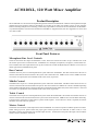
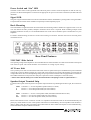
ACM120XL
120w Mixer Amplifier
Operating Manual
ACM120XL, 120 Watt Mixer Amplifier
Product Description
The ACM120XL is a 120 watt mixer amplifier designed for commercial installations. It features 8 microphone/line input
channels and can be used for either low impedance (4 or 8 ohm) or 70v/100v line speaker systems. A host of unique
features including multiple levels of muting, a VOX relay output and VCA master level control make the ACM120XL a
very flexible amplifier. The unit can be mounted in a standard 19” equipment rack (rack ears supplied) or it can be used
on a shelf or table.
Front Panel Features
Microphone/Line Level Controls
The level controls for the 8 inputs are labeled Ch 1-Ch 8. These level controls are used to set up a suitable “mix” of all
the various input sources connected to the ACM120XL. For example, microphones, CD players, cassette decks etc.
Once a suitable mix of all inputs has been set up, the overall level can then be adjusted by the “Master” level control on
the far right of the ACM120XL front panel.
Bass Control
The Bass control is part of a 3-band equalization system within the ACM120XL. The Bass control allows the user to
increase or decrease the amount of bass in the system. The control allows for 12dB of cut or boost at 100Hz. If no bass
cut or boost is required, the control should be left in the center (0) position.
Middle Control
The Mid control is part of a 3 band equalization system within the ACM120XL. The Mid control allows the user to
increase or decrease the amount of mids in the system. The control allows for 10dB of cut or boost at 600Hz. Depending
on the speakers and application, a small cut (decrease) in the mids normally makes the system sound ‘warmer’. If no mid
cut or boost is required, the control should be left in the center (0) position.
Treble Control
The Treble control is part of a 3 band equalization system within the ACM120XL. The Treble control allows the user to
increase or decrease the amount of treble in the system. The control allows for 10dB of cut or boost at 10kHz. Generally,
a small increase of the treble control makes a system sound ‘brighter’. If no treble cut or boost is required, the control
should be left in the center (0) position.
Master Control
The master control sets the overall output level of the ACM120XL. It is used in conjunction with the input level controls.
When setting up levels, please ensure that proper gain structure practices are followed. In other words, it is not
advisable to run the input channels at 10 and the output level at 1. Instead, aim to keep all of the input controls and the
master control at around the same level.
Power Switch and “On” LED
The black rocker switch on the right hand side of the front panel is used to switch the amplifier on and off. The ‘up’
position is on. When the amplifier is connected to an appropriate AC power source and is switched on, the blue LED will
illuminate.
Signal LED
The green “Signal” LED located next to the On LED indicates that the ACM120XL is passing audio. The signal LED is
a simple method to trouble-shoot installations especially in multi-amplifier projects.
Rack Mounting
The ACM120XL is supplied with rack ears attached to allow mounting within a standard 19” equipment rack. As is the
case with almost all audio products, adequate ventilation and air flow is required. When installing multiple ACM
amplifiers within the one rack, it is recommended that at least 1 rack unit of ventilation space is left between every two
amplifiers.
For table or shelf mounting, the rack ears can be removed using a screwdriver. Once the rack ears are removed, please
reinstall the screws.
Rear Panel Features
230V/240V Slide Switch
The operating voltage of the amplifier is user selectable between 230V and 240V via a slide switch located on the top left
side of the rear panel. This switch should be set to match the AC voltage of your country.
AC Power Inlet
The 3 pin IEC power inlet is located on the bottom left of the rear panel and accepts a standard mains power lead fitted
with an IEC connector. Before plugging in a power lead, please check the rear panel of the amplifier to ensure that the
voltage label shows the correct AC operating voltage for your part of the world. The inlet is equipped with an in-built AC
fuse holder fitted with a 4 Amp slow blow fuse plus a spare fuse. Power consumption is 250 watts (max).
---Please ensure that the mains power cord is disconnected before attempting to check or replace this fuse.---
Speaker Output Terminal Strip
Located on the top left of the rear panel is the speaker output terminal strip. Reading from left to right, the connections
are:
COM Common or “-” for low impedance speaker loads (4 or 8 ohms).
4
Positive “+” for 4 ohm speaker loads (use with common)
8
Positive “+” for 8 ohm speaker loads (use with common)
COM
70
100
Common or “-” for 70v or 100v speaker loads (maximum load of 80 ohms at 100v)
Positive “+” for 70v line speaker loads (use with common)
Positive “+” for 100v line speaker loads (use with common)
Please ensure that the correct “Common” is used. Low impedance and 70/100v loads can be used simultaneously but
please pay careful attention to the overall speaker load. When used individually, the low impedance load should be 4
ohms or higher while the 100v line load should not fall below 80 ohms. When both outputs are used simultaneously,
ensure that neither output is loaded to maximum.
VOX Relay Output
The terminal strip to the immediate right of the AC inlet features a relay output. This relay is activated when signal is
present on any of the priority inputs. This would normally be inputs 1, 2 and 3 however some or all of these channels can
be removed from the priority bus via internal links (see “Muting” further on in this manual). The unit is shipped from the
factory with inputs 1, 2 and 3 having priority so assuming that this has not been changed, then signal from any of these
inputs will activate the VOX relay circuit.
The relay outputs are C (Common), NO (Normally Open) and NC (Normally Closed). The NO or NC selection provides
the installer with the option of the relay either opening or closing a contact. This feature is normally used in conjunction
with relay override attenuators (volume controls). In this application, the relay output could trigger a power supply
which in turn bypasses the remote attenuators. The result is that priority inputs will always be heard irrespective of the
attenuator setting. The relay contacts are 0.5 amps at 100VAC.
VCA Control
An external pot (500 ohm to 1K) can be connected to the ACM120XL for remote control of the master level. While a 1K
pot can used, better results (smoother volume adjustment) can be obtained by using a 500 ohm pot. The external pot is
governed by the master level of the amplifier allowing the installer to set the volume, then lock the amplifier in a rack
leaving the user with just a master volume control that cannot go beyond the level set on the master (front panel) control.
Connection is via a 2 wire terminal strip on the rear panel of the amplifier.
Tone Generator
The ACM120XL includes a 4 tone generator module featuring Alert, Evacuate, Pre-Announce and Bell tones. All 4 tones
can be activated individually using the rear panel terminal strip. Shorting “Common” to the relevant tone name will
activate that particular tone.
The volume level of the tone is set via an internal pot (R63) which is located to the far right (when looking from the front)
of the front mixer PCB. The pot is labelled R63 and sets the level of all 4 tones. Please note that the level of the tones is
not affected by the “Master” control on the front panel.
When any of the 4 tones are activated, inputs 4 to 8 are muted. Inputs 1, 2 and 3 on the other hand will mix with the tones
and can be used at the same time.
Insert Point
The ACM120XL includes an Insert Point to allow for connection of signal processors such as equalisers, compressors
or Feedback Exterminators. The Insert Point is located (electronically) between the mixer and power amplifier sections of
the ACM120XL. It allows for the “mixed” output of the ACM120XL to be processed externally and then returned to the
power amplifier section of the ACM120XL.
The Insert Point is a 3 conductor (Tip, Ring, Sleeve) socket which accepts a standard stereo 6.35mm (1/4”) jack. The one
jack allows for signals to be “sent” to the processor and then “returned” to the power amplifier. The connections are:
Tip
Amplifier in. This is the return signal from the processor
Ring
Mix Output. This is the signal from the mixer stage which is to be sent to the processor
Sleeve This is the ground connection
When an external processor is used via the insert point, it only affects the power amplifier section of the ACM120XL.
The tape output remains unprocessed.
Tape Output
The ACM120XL includes a tape recorder output with dual RCA connectors. Although the output signal is mono, dual
RCA’s are provided to allow for easy connection to domestic or professional tape recorders.
The output level of the tape output is governed by the 8 input controls of the ACM120XL. The front panel master
control does not affect the tape output. In a practical situation, this allows for “on the fly” changes to the power amplifier
level (to turn the PA system up or down) without affecting the signal being recorded.
Line Output
A 3 pin male XLR socket is provided to allow for connection to additional power amplifiers. The line level signal is the
mixer output of the ACM120XL allowing this “mixed” signal to be split to other amplifiers. This is most commonly used
when more power (than the 120 watts of the ACM120XL) is required. In this situation, a standard microphone lead is
used to connect the line output of the ACM120XL to the line input of a power amplifier. The speaker load then needs to
be split into two (one for each amplifier) making sure that each amplifier is driving no more than it’s recommended load.
The line output is a balanced 700mV signal which can be used to connect (daisy-chain) up to 6 power amplifiers. If more
than 6 amplifiers are required, a distribution amplifier is recommended.
Microphone Inputs
The ACM120XL includes 8 microphone and line inputs. The microphone inputs are via 3 pin XLR female sockets. The
microphone inputs are 200 ohm and are suitable for a wide range of dynamic or electret microphones. When using
electret microphones, phantom power should be enabled for those particular inputs. Phantom power (15v DC) is
available on all XLR inputs and can be switched on or off per channel. To enable phantom power on a particular input
channel, simply flip (on the rear panel) dip switch 3 (for that channel) to the on position.
Line Inputs
The ACM120XL includes 8 microphone and line (auxiliary) inputs. The line inputs are via dual RCA connectors per
channel. Although the ACM120XL is a mono amplifier, dual RCA’s are provided to allow for easy connection to
domestic or professional line sources. The line inputs are suitable for a wide range of products including tuners, cassette
decks and CD players. As the output signal from line sources can vary immensely, four sensitivity settings are available
per line input. These settings are adjustable via dip switches 1 and 2 per channel. The options are:
Dip Switch 1 off, 2 off
90mV at 47K ohm
Dip Switch 1on, 2 off
9dB pad (cut)
Dip Switch 1off, 2 on
12dB pad (cut)
Dip Switch 1on, 2 on
15dB pad (cut)
Dip Switch 3 is for the XLR microphone input and switches phantom power on and off (see “Microphone Inputs”).
Simultaneous Use of Mic and Line Inputs Per Channel
The ACM120XL has 8 microphone and 8 line inputs. In most situations only the XLR or the dual RCA’s would be used
on a particular channel. In some circumstances however, more channels may be needed in which case both the XLR and
RCA inputs can be used simultaneously per channel. When using both a mic and line input per channel, both inputs are
mixed and are controlled simultaneously via the channel level control.
Line Input Sensitivity
Four sensitivity adjustments are provided for each line input. See “Line Inputs”.
Phantom Power
15v DC Phantom Power is selectable per XLR microphone input. See “XLR Microphone Inputs”. Phantom Power should
only be used on balanced electret microphones. Using phantom power with unbalanced microphones may damage the
microphone.
Muting
The ACM120XL includes an advanced priority/muting system which is installer adjustable. When shipped, the
ACM120XL has three priority inputs. From the factory, Input 1 has overall priority and mutes inputs 2-8 when signal is
present. Input 2 has secondary priority and mutes inputs 3-8 when signal is present. Input 3 has a third level of priority
and mutes inputs 4-8 when signal is present. Inputs 4-8 have no priority and are mixed. All muting in the ACM120XL is
activated by signal (VOX) whether it be on the XLR or RCA inputs.
A number of muting options are available and can be altered via a series of internal links located on the front mixer board
behind inputs 1and 2.
Muting for any of the first three inputs can be disabled. The muting circuit of input 1 can be disabled by moving the
jumper labelled JP1 (located on the front mixer PCB behind input 1 and 2’s level controls). Simply move the jumper
towards the back of the chassis to disable muting from input 1.
To disable muting from input 2, simply move jumper JP2 towards the back of the chassis.
To disable muting from input 3, simply move jumper JP3 towards the back of the chassis.
Another feature of the muting circuit of the ACM120XL is the ability to have inputs 1 and 2 on the same priority level.
This is handy for situations where phone paging and microphone paging (for example) are of equal importance. In this
mode, both inputs can be used at the same time and both will mute all remaining channels. This feature is also handy for
emergency systems where signal from a pre-recorded message could be mixed with a live microphone. To set inputs 1
and 2 to the same priority level, move jumper JP4 towards the front of the chassis and remove and discard jumper J6.
Please note that both jumpers (J4 moved and J6 removed) need to be adjusted for this feature to work.
Important Safety Information
1. Save the carton and packing material even if the equipment has arrived in good condition. Should you ever
need to ship the unit, use only the original factory packing.
2. Read all documentation before operating your
equipment. Retain all documentation for future reference.
13. Do not block fan intake or exhaust ports. Do not
operate equipment on a surface or in an environment
which may impede the normal flow of air around the
unit, such as a bed, rug, weathersheet, carpet, or completely enclosed rack. If the unit is used in an extremely
dusty or smoky environment, the unit should be periodically “blown free” of foreign matter.
3. Follow all instructions printed on unit chassis for
proper operation.
14. Do not remove the cover. Removing the cover will
expose you to potentially dangerous voltages. There
are no user serviceable parts inside.
4. Do not spill water or other liquids into or on the
unit, or operate the unit while standing in liquid.
15. Do not drive the inputs with a signal level greater
than that required to drive equipment to full output.
5. Make sure power outlets conform to the power
requirements listed on the back of the unit.
16. Do not connect the inputs / outputs of amplifiers
or consoles to any other voltage source, such as a
battery, mains source, or power supply, regardless of
whether the amplifier or console is turned on or off.
6. Do not use the unit if the electrical power cord is
frayed or broken. The power supply cords should be
routed so that they are not likely to be walked on or
pinched by items placed upon or against them, paying
particular attention to cords and plugs, convenience receptacles, and the point where they exit from the
appliance.
7. Always operate the unit with the AC ground wire
connected to the electrical system ground. Precautions
should be taken so that the means of grounding of a
piece of equipment is not defeated.
8. Mains voltage must be correct and the same as
that printed on the rear of the unit. Damage caused
by connection to improper AC voltage is not covered by
any warranty.
9. Have gain controls on amplifiers turned down during power-up to prevent speaker damage if there are high
signal levels at the inputs.
10. Power down & disconnect units from mains voltage before making connections.
11. Never hold a power switch in the “ON” position
if it won’t stay there itself!
12. Do not use the unit near stoves, heat registers,
radiators, or other heat producing devices.
17. Do not run the output of any amplifier channel
back into another channel’s input. Do not parallel- or series-connect an amplifier output with any
other amplifier output.
Audio Telex Communications Pty Ltd is not responsible for damage to loudspeakers for any reason.
18. Do not ground any red (“hot”) terminal. Never
connect a “hot” (red) output to ground or to another “hot” (red) output!
19. Non-use periods. The power cord of equipment
should be unplugged from the outlet when left unused for a long period of time.
20. Service Information Equipment should be serviced by qualified service personnel when:
A. The power supply cord or the plug has been
damaged.
B. Objects have fallen, or liquid has been spilled into
the equipment
C. The equipment has been exposed to rain
D. The equipment does not appear to operate normally,
or exhibits a marked change in performance
E. The equipment has been dropped, or the enclosure
damaged.
Engineered by Audio Telex Communications Pty Ltd, Sydney, Australia
A.B.N. 78 001 345 482 Inc in NSW
www.audiotelex.com.au
Export Sales & Corporate Head Office
Private Bag 149, Silverwater NSW 1811
149 Beaconsfield Street, Silverwater NSW 2128
Australia
Ph: 61-2- 9647 1411
Fax: 61-2-9748 2537
E-mail: [email protected]
Sydney (NSW & ACT Sales)
Private Bag 149, Silverwater NSW 1811
149 Beaconsfield Street, Silverwater NSW 2128
Ph: (02) 9647 1411
Fax: (02) 9648 3698
E-mail: [email protected]
Melbourne (Vic & Tas Sales)
P.O. Box 131, Blackburn South VIC 3130
22/277 Middleborough Road, Box Hill VIC 3128
Ph: (03) 9890 7477
Fax: (03) 9890 7977
E-mail: [email protected]
Brisbane (Qld Sales)
P.O. Box 871, Fortitude Valley QLD 4006
42 Commerical Road, Fortitude Valley QLD 4006
Ph: (07) 3852 1312
Fax: (07) 3252 1237
E-mail: [email protected]
Adelaide (SA & NT Sales)
P.O. Box 157, Hindmarsh SA 5001
31 Walsh Street, Thebarton SA 5031
Ph: (08) 8352 4444
Fax: (08) 8352 4488
E-mail: [email protected]
Perth (WA Sales)
P.O. Box 404, North Perth WA 6906
299 Fitzgerald Street, West Perth WA 6005
Ph: (08) 9228 4222
Fax: (08) 9228 4233
E-mail: [email protected]
Auckland (NZ Sales)
P.O. Box 512, Albany 1331
Unit B, 11 Piermark Drive, Albany 1331
Ph: (09) 415 9426
Fax: (09) 415 9894
E-mail: [email protected]