1
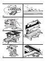
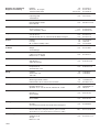
®
DW711
Dansk
1
Deutsch
8
English
15
Español
22
Français
29
Italiano
36
Nederlands
43
Norsk
50
Português
57
Suomi
64
Svenska
71
Türkçe
78
EÏÏËÓÈη
85
Copyright DEWALT
2
1
13
3
4
12
5
6
7
8
10
11
9
A1
14
19
A2
15 16
17
18
20 21 22 23
24 21 22 20
26
27
A3
25
25
A4
31
28
21
32 30
33
29
B
A5
35
C1
34
C2
36
C3
C4
38
18
D1
55
D2
37
40
39
44
18
D3
E1
42 40
E3
E2
4
43
E4
E5
41
46
44
12
45
F1
,,
,
,,
,,,
,,,
,,
,,,
,
,,,
F2
12 50
47
51
49
48
49
F3
G1
8
45
7
H1
G2
44
45
11
H2
52
10
H3
31
2 mm
53
5 mm
54
H4
J1
56
J2
2
7
K
11
8
L
15
57
M
N
ENGLISH
TABLE TOP MITRE SAW DW711
Congratulations!
EC-Declaration of conformity
You have chosen a DEWALT Power Tool. Years of experience, thorough
product development and innovation make DEWALT one of the most
reliable partners for professional Power Tool users.
Table of contents
Technical data
EC-Declaration of conformity
Safety instructions
Package contents
Description
Electrical safety
Mains plug replacement (U.K. & Ireland only)
Using an extension cable
Assembly and adjustment
Instructions for use
Maintenance
Guarantee
en - 1
en - 1
en - 2
en - 2
en - 3
en - 3
en - 3
en - 3
en - 3
en - 5
en - 6
en - 7
Technical data
Voltage
(U.K. & Ireland only)
Power input
Power output
Blade diameter
Blade bore
Max. blade speed
Max. cross-cut capacity at 90°
Max. cross-cut capacity 45°
Max. depth of cut 90°
Max. depth of bevel cut 45°
Mitre (max. positions)
V
V
W
W
mm
mm
min-1
mm
mm
mm
mm
left
right
left
Bevel (max. positions)
Compound cuts
Max. depth of cut at 90° mitre, 45° bevel
Max. depth of cut at 90° mitre, 48° bevel
Max. depth of cut at 45° mitre, 45° bevel
Max. depth of cut at 45° mitre, 48° bevel
Max. depth of cut at 48° mitre, 45° bevel
Max. depth of cut at 48° mitre, 48° bevel
Max. ripping capacity left/right
Max. depth of cut bench saw
Automatic blade brake time
Weight
Fuses:
Europe
U.K. & Ireland
DW711
230
230/115
1,300/1,100
900/800
260
30
2,750/2,850
140
100
96
45
48°
48°
48°
DW711
DEWALT declares that these Power Tools have been designed in compliance
with: 98/37/EEC, 89/336/EEC, 73/23/EEC, EN 61029-1,
prEN 61029-2-11, EN 55014, EN 55014-2, EN 61000-3-2 & EN 61000-3-3.
For more information, please contact DEWALT at the address below or
refer to the back of the manual.
Level of sound pressure according to 86/188/EEC & 98/37/EEC,
measured according to prEN 61029-2-11:
DW711
LpA
(sound pressure)
LWA (acoustic power)
dB(A)*
90.8
dB(A)
98.8
* at the operator’s ear
Take appropriate measures for the protection of hearing if the
sound pressure of 85 dB(A) is exceeded.
Weighted root mean square acceleration value according to
prEN 61029-2-11:
DW711
< 2.5 m/s2
TÜV Rheinland
Product and Safety GmbH (TRPS)
Am Grauen Stein 1
D-51105 Köln
Germany
Cert. No.
BM 9910407
mm
mm
mm
mm
mm
mm
mm
mm
s
kg
230 V tools
230 V tools
48
45
48
45
48
45
180/60
0 - 50
< 10.0
24
Director Engineering and Product Development
Horst Großmann
10 Amperes, mains
13 Amperes, in plugs
The following symbols are used throughout this manual:
Denotes risk of personal injury, loss of life or damage to the
tool in case of non-observance of the instructions in this
manual.
Denotes risk of electric shock.
Sharp edges.
en - 1
DEWALT, Richard-Klinger-Straße 40,
D-65510, Idstein, Germany
15
ENGLISH
Safety instructions
When using Power Tools, always observe the safety regulations
applicable in your country to reduce the risk of fire, electric shock and
personal injury. Read the following safety instructions before attempting
to operate this product. Keep these instructions in a safe place!
General
1 Keep work area clean
Cluttered areas and benches can cause accidents.
2 Consider work area environment
Do not expose Power Tools to humidity. Keep work area well lit.
Do not use Power Tools in the presence of flammable liquids or gases.
3 Guard against electric shock
Prevent body contact with earthed surfaces (e.g. pipes, radiators,
cookers and refrigerators).
For use under extreme conditions (e.g. high humidity, when metal
swarf is being produced, etc.) electric safety can be improved by
inserting an isolating transformer or a (FI) earth-leakage circuit-breaker.
4 Keep children away
Do not let children come into contact with the tool or extension cord.
Supervision is required for those under 16 years of age.
5 Extension cords for outdoor use
When the tool is used outdoors, always use extension cords intended
for outdoor use and marked accordingly.
6 Store idle tools
When not in use, Power Tools must be stored in a dry place and
locked up securely, out of reach of children.
7 Dress properly
Do not wear loose clothing or jewellery. They can be caught in moving
parts. Preferably wear rubber gloves and non-slip footwear when
working outdoors. Wear protective hair covering to keep long hair out
of the way.
8 Wear safety goggles
Also use a face or dust mask in case the operations produce dust or
flying particles.
9 Beware of maximum sound pressure
Take appropriate measures for the protection of hearing if the sound
pressure of 85 dB(A) is exceeded.
10 Secure workpiece
Use clamps or a vice to hold the workpiece. It is safer and it frees both
hands to operate the tool.
11 Do not overreach
Keep proper footing and balance at all times.
12 Avoid unintentional starting
Do not carry the plugged-in tool with a finger on the switch. Be sure
that the switch is released when plugging in.
13 Stay alert
Watch what you are doing. Use common sense. Do not operate the
tool when you are tired.
14 Disconnect tool
Shut off power and wait for the tool to come to a complete standstill
before leaving it unattended. Unplug the tool when not in use,
before servicing or changing accessories.
15 Remove adjusting keys and wrenches
Always check that adjusting keys and wrenches are removed from the
tool before operating the tool.
16 Use appropriate tool
The intended use is described in this instruction manual. Do not force
small tools or attachments to do the job of a heavy-duty tool. The tool
will do the job better and safer at the rate for which it was intended.
Warning! The use of any accessory or attachment or performance of
any operation with this tool, other than those recommended in this
instruction manual may present a risk of personal injury.
16
17 Do not abuse cord
Never carry the tool by its cord or pull it to disconnect from the socket.
Keep the cord away from heat, oil and sharp edges.
18 Maintain tools with care
Keep the tools in good condition and clean for better and safer
performance. Follow the instructions for maintenance and changing
accessories. Inspect the tool cords at regular intervals and,
if damaged, have them repaired by an authorized DEWALT repair
agent. Inspect the extension cords periodically and replace them if
damaged. Keep all controls dry, clean and free from oil and grease.
19 Check for damaged parts
Before using the tool, carefully check it for damage to ensure that it will
operate properly and perform its intended function. Check for
misalignment and seizure of moving parts, breakage of parts and any
other conditions that may affect its operation. Have damaged guards
or other defective parts repaired or replaced as instructed.
Do not use the tool if the switch is defective. Have the switch replaced
by an authorized DEWALT repair agent.
20 Have your tool repaired by an authorized DEWALT repair agent
This Power Tool is in accordance with the relevant safety regulations.
To avoid danger, electric appliances must only be repaired by qualified
technicians.
Additional safety rules for mitre saws
• Make sure that the blade rotates in the correct direction. Keep the
blade sharp. Do not use blades of larger or smaller diameter than
recommended. For the proper blade rating refer to the technical data.
• Make sure all locking knobs and clamp handles are tight before starting
any operation.
• Check periodically that the motor air slots are clean and free of chips.
• Disconnect the machine from the mains before carrying out any
maintenance work or when changing the blade.
• Before using any accessory consult the instruction manual.
The improper use of an accessory can cause damage.
• Allow the motor to reach full speed before cutting.
• Raise the blade from the kerf in the workpiece prior to releasing the switch.
• Do not wedge anything against the fan to hold the motor shaft.
• Never place either hand in the blade area when the saw is connected
to the electrical power source.
• Do not attempt to cut excessively small pieces.
• Never attempt to stop a machine in motion rapidly by jamming a tool or
other means against the blade; serious accidents can be caused
unintentionally in this way.
• Do not use cracked or damaged saw blades.
• Do not use any abrasive discs.
• Do not cut ferrous metals, non-ferrous metals or masonry.
Additional safety rules for saw benches
• Make sure that the blade rotates in the correct direction and that the
teeth are pointing to the front of the saw bench.
• Make sure that the riving knife is adjusted to the correct distance form
the blade - maximum 5 mm.
• Never operate the saw without the upper and lower guards in place.
• Use a push stick at all times, and ensure that you do not place hands
closer than 150 mm from the saw blade while cutting.
• Do not use the saw for cutting any material other than wood.
Package contents
The package contains:
1 Assembled table top mitre saw
1 Parallel rip fence
1 Guard for bench saw position
1 Bottom guard for bench saw position
1 Push stick
en - 2
ENGLISH
1
1
1
1
1
1
Allen key 4 mm
Allen key 6 mm
Two-pin spanner
Dust extraction adapter for top guard
Instruction manual
Exploded drawing
• Check for damage to the tool, parts or accessories which may have
occurred during transport.
• Take the time to thoroughly read and understand this manual prior to
operation.
• Remove the saw from the packaging material carefully.
• Release the head lock down knob to raise the head of the machine.
Description (fig. A1 - A4)
Your DEWALT table top mitre saw has been developed for professional
applications. This high precision machine can be easily and quickly set to
crosscut, bevel, mitre, or compound mitre.
A1
1 On/off-switch
2 Head lock up release lever
3 Additional saw bench table locking knob
4 Moveable lower blade guard
5 Fixed table
6 Blade slot
7 Positive stop lever
8 Mitre clamping knob
9 Rotating table/mitre arm
10 Mitre scale
11 Fence
12 Bevel clamp handle
13 Head lock down knob
Mains plug replacement (U.K. & Ireland only)
• Should your mains plug need replacing and you are competent to do
this, proceed as instructed below. If you are in doubt, contact an
authorized DEWALT repair agent or a qualified electrician.
• Disconnect the plug from the supply.
• Cut off the plug and dispose of it safely; a plug with bared copper
conductors is dangerous if engaged in a live socket outlet.
• Only fit 13 Amperes BS1363A approved plugs fitted with the correctly
rated fuse (1).
• The cable wire colours, or a letter, will be marked at the connection
points of most good quality plugs. Attach the wires to their respective
points in the plug (see below). Brown is for Live (L) (2), blue is for
Neutral (N) (4) and green/yellow is for Earth (E).
• Before replacing the top cover of the mains plug ensure that the cable
restraint (3) is holding the outer sheath of the cable firmly and that the
leads are correctly fixed at the terminal screws.
Never use a light socket.
Never connect the live (L) or neutral (N) wires to the earth pin
marked E or .
For 115 V units with a power rating exceeding 1500 W, we recommend to
fit a plug to BS4343 standard.
Using an extension cable
A2
14 Saw bench table
15 Riving knife
16 Upper saw blade guard
17 Rip fence
18 Fixed lower guard (for use in bench saw position)
19 Attachment mounting holes
Optional accessories
A3
20 Table end plate (DE3490)
21 Support guide rails 1000 mm (DE3494)
22 Material support plate (DE3495)
23 Material clamp (DE3499)
24 Swivelling stop (DE3462)
25 Adjustable stand 760 mm (max. height) (DE3477)
26 Legstand (DE3493)
A4
27 Length stop for short workpieces (to be used with guide rails [21])
(DE3492)
A5
28 Legstand (DE3493)
29 Roller table (DE3497)
Electrical safety
The electric motor has been designed for one voltage only. Always check
that the power supply corresponds to the voltage on the rating plate.
en - 3
If an extension cable is required, use an approved extension cable suitable
for the power input of this machine (see technical data). The minimum
conductor size is 1.5 mm2. When using a cable reel, always unwind the
cable completely. Also refer to the table below.
Conductor size (mm2)
0.75
1.00
1.50
2.50
4.00
Voltage
230
Amperes
0 - 2.0
2.1 - 3.4
3.5 - 5.0
5.1 - 7.0
7.1 - 12.0
12.1 - 20.0
Cable rating (Amperes)
6
10
15
20
25
Cable length (m)
7.5 15
25 30
Cable rating (Amperes)
6
6
6
6
6
6
6
6
6
6
6
6
10 10
10 10
15 15
15 15
20 20
20 20
45
60
6
6
10
15
20
25
6
6
15
15
20
-
Assembly and adjustment
Prior to assembly and adjustment always unplug the tool.
Mounting the upper guard (fig. B)
• Fasten the guard (30) to the riving knife (31) with the bolt (32).
Place the washer and wingnut onto the other end of the bolt and tighten.
• Fit the dust spout (33) to the blade guard.
A separate dust kit is available as an option (DE7779).
17
ENGLISH
Mounting and adjusting the rip fence (fig. C1 - C4)
The rip fence consists of a fixed and a sliding fence.
• Loosen the fence support locking knob (34) which holds the clamping
plate in position (fig. C1).
• Slide the fence onto the front of the table using the U-shaped slot as
the guide (fig. C2 & C3).
• Slide the fence towards the blade and tighten the locking knob.
Check that the fence is parallel to the blade. If not, then adjust as
follows (fig. C4).
• Loosen the sliding fence locking knob (35) (fig. C1) and slide the sliding
fence backwards in order to obtain full sight on the two holes (36)
(fig. C4) in the top of the fence.
• Using the small Allen key, loosen the two Allen screws fastening the
fence to the fence support. Access is gained through the two holes in
the top of the fence.
• Adjust the fence so that it is parallel to the blade by checking the
distance between the blade and the fence at the front and rear of the
blade.
• When the adjustment has been carried out, re-tighten the Allen screws
and check again that the fence is parallel to the blade.
The maximum diameter blade that can be fitted is 260 mm.
Adjusting the saw blade (fig. E1)
If the saw blade is wobbling during start up and run down, then adjust as
follows.
• Loosen the screw for the arbor collar (40) and rotate the blade (44)
a quarter turn.
• Retighten the screw and check to see if the blade has any wobble.
• Repeat these steps until the blade wobble has been eliminated.
Checking and adjusting the blade to the table (fig. F1 - F3)
• Ensure that the head is locked in the 0° mitre position.
• Release the bevel clamp handle (12) by pushing it down (fig. F1).
• Press the saw head to the right to ensure it is fully vertical and tighten
the bevel clamp handle.
• Place a set square (45) on the table and up against the blade (44)
(fig. F1).
Do not touch the tips of the blade teeth with the square.
Adjusting the saw bench table (fig. A1, D1 - D3)
The table slides up and down manually and is held at the required height
with two locking knobs. The locking knobs are located under the table, the
main at the rear of the motor (37) (fig. D1) and the additional at the front to
the left of the saw blade (3) (fig. A1).
• Loosen the knobs and position the table as required.
• When the unit is being used as a saw bench, the fixed lower guard (18)
should always be used (fig. D3). Remove the M10 hex nut (38) and fit
the guard as shown (fig. D2). Replace the nut and tighten so that the
guard is fixed in position. The machine should always operate in the
bench position with this guard in place.
Mounting the saw blade (fig. E1 - E5)
The teeth of a new blade are very sharp and can be
dangerous.
• Take the pin spanner (39) and place the two holes on the outside of the
outer arbor collar (40) (fig. E1).
• In the centre is a large Allen screw. Place the short leg of the 6 mm
Allen key (41) through the hole in the metal guard main frame and into
the Allen screw.
• This screw has a left-handed thread, therefore holding the spanner
firmly, turn the Allen key clockwise to loosen.
• Take out the screw and washer. Remove the outer arbor collar.
• The collar (40) has two locking projections (42) that pass through the
blade and into the inner arbor collar and locate one on each side of the
spindle against the flats provided (fig. E2 & E3).
• The blade has a 30 mm bore, and is located on a step flange on the
inner arbor collar.
• The movable blade guard (4) must be retracted. To do so, take out the
Allen screw (43) on the right-hand side of the fixed nose piece and slide
the guard back. Leave retracted (fig. E4).
• Remove the blade (44) (fig. E1).
• To fit a new blade just reverse the process, taking care to ensure that
the blade is seated on the inner flange with the teeth pointing
downwards towards the table.
• Ensure that the two projections on the outer collar are seated properly
through the inner collar and onto the flats on the spindle.
• Also, when replacing the Allen screw through the hole ensure that the
washer is held in position behind the frame (fig. E5).
• Put the washer back on the Allen screw and tighten the screw securely.
• Remove the guard back down and replace the Allen screw (43) (fig. E4).
18
If adjustment is required, proceed as follows:
• Loosen the bevel clamp handle.
• Using an Allen key, adjust the screw (46) until the head is at a perfect
90° (fig. F2).
• Check that the bevel indicator (47) indicates 0° on the bevel scale (48)
(fig. F3).
• If not, loosen the two screws (49) move the scale to read 0° and
tighten the two screws.
Checking and adjusting the bevel angle (fig. F3, G1 & G2)
Your saw has a bevel adjustment handle with knurled end (50) that allows
the fixed position to be set at 45° or 48° until the head is at a perfect 90°
(fig. G1).
- Out = 48°
- In = 45°
• Push in the 45°/48° adjustment handle (50) (fig. G1).
• Push the bevel clamp handle (12) down (fig. G1).
• Move the saw head to the left, to its maximum bevel position.
• Check that the angle is exactly 45° using a protractor (fig. G2).
• If adjustment is required, turn the bevel adjustment screw (51) (fig. F3)
until the saw head is exactly 45°. Repeat the same steps to adjust to
48° with the adjustment handle (50) (fig. G1) in the “Out” position.
While performing this adjustment, it is advisable to take the
weight of the saw head by holding it. This will make it easier to
turn the adjustment screw.
Checking and adjusting the blade to the fence (fig. A1, H1 - H4)
• Loosen the mitre clamping knob (8) by turning counterclockwise
(fig. H1)
• Pull down the head and lock it in this position tightening the head lock
down knob (13) (fig. A1).
• Lift the positive stop lever (7) (fig. H1) and swing the head until the stop
locates it at 0° mitre position. Do not tighten the clamping knob (8)
(fig. H1).
• Check that the two 0° markings (52) on the scale (10) are just visible
(fig. H2).
• Place a square (45) against the left side of the fence (11) and blade (44)
(fig. H3).
Do not touch the tips of the blade teeth with the square.
en - 4
ENGLISH
If the saw blade is not exactly at 90° to the fence:
• Loosen the two screws (53) and move the scale/head assembly left or
right until the blade is at 90° to the fence as measured with the square
(fig. H4).
• Lock the mitre clamping knob (9) (fig. A1).
• Tighten the two screws (53) (fig. H4).
Make sure the rear edge of the mitre scale keeps in contact
with the two location lugs (54) at all times.
Adjusting the riving knife (fig. A1, D1, J1 & J2)
The correct position is for the top of the riving knife (31) to be no more
than 2 mm below the highest tooth of the blade and the body of the radius
to be a maximum of 5 mm from the tips of the saw blade teeth (fig. J1).
• Loosen the table locking knobs, both main (37) (fig. D1) and additional (3)
(fig. A1), but do not take them off.
• Use the Allen key to remove the screw (55) from the rear table column
(fig. D1). Take the nut and washer off the other end of the screw.
• Remove the table.
• The riving knife (31) (fig. J1) is fastened by a large Allen screw (56)
towards the rear of the right-hand side under the table (fig. J2).
• To adjust the riving knife, loosen the Allen screw which allows both the
bracket to rotate and the riving knife to move up and down.
• After loosening, rotate the bracket and slide the knife either up or down
until the correct position is attained.
• Retighten the screw (56) firmly (fig. J2).
• Replace the table and replace the Allen screw assembly (55) (fig. D1).
• Set the table to the proper height needed.
• Tighten the table locking knobs (fig. A1 & D1).
Lubrication
This machine requires no additional lubrication. The bearings of the motor
are pre-lubricated and watertight.
• Avoid using oil or grease as this can cause clogging with sawdust and
chips and create problems.
• Clean the parts subject to accumulation of sawdust and chips
periodically with a dry brush.
Instructions for use
• Always observe the safety instructions and applicable regulations.
The attention of UK users is drawn to the “woodworking
machines regulations 1974” and any subsequent amendments.
• Ensure the material to be sawn is firmly secured in place.
• Apply only a gentle pressure to the tool and do not exert side
pressure on the saw blade.
• Avoid overloading.
• Always remove the dust from the machine after using to
ensure the lower guard operates properly.
Prior to operation:
• Install the appropriate saw blade. Do not use excessively worn blades.
The maximum rotation speed of the tool must not exceed that of the
saw blade.
• Do not attempt to cut excessively small pieces.
• Allow the blade to cut freely. Do not force.
• Allow the motor to reach full speed before cutting.
• Make sure all locking knobs and clamp handles are tight.
Switching on and off (fig. A)
• To switch the machine on, press the on/off switch (1).
• To switch the machine off, press the on/off switch again.
en - 5
Quality of cut
The smoothness of any cut depends on a number of variables, e.g. the
material being cut. Please see the chart below for the recommended saw
blades applications.
Ensure that the material does not creep while cutting; clamp it
securely in place. Always let the blade come to a full stop
before raising the arm. If small fibres of wood still split out at
the rear of the workpiece, stick a piece of masking tape on the
wood where the cut will be made. Saw through the tape and
carefully remove tape when finished.
Setting the mitre (fig. A1)
The mitre arm can be preset to 0°, 15°, 22.5°, 30° and 45° left and right.
It is also possible to set the mitre angle to 48°.
• Loosen the mitre clamping knob (8) and lift the positive stop lever (7)
to release the mitre arm (9).
• Move the arm to the required angle and lock it using the mitre clamping
knob (8).
• Align the mitre arm as shown in fig. H1 - H3 by moving the edge of the
arm to the required mark on the scale.
When mitre cutting, ensure that the off-cut is not wedged
between the blade and the fence, i.e. the off-cut angle is greater
than 90° to avoid that the off-cut is picked up by the blade.
Setting the bevel (fig. G1)
• Set the 45°/48° adjustment handle (50) to the required position.
- Out = 48°
- In = 45°
• Loosen the bevel clamp handle (12) and bevel the head to the left;
there are marked positions at 0°, 15°, 30°, 33.85° and 45°.
• Hold the head firmly and do not allow it to fall.
• Holding the head, lock the bevel clamp handle securely.
Sawing in mitre saw mode
It is dangerous to operate without guarding. Guards must be in position
when sawing.
Ensure that aluminum workpieces are clamped securely.
Vertical straight cross cut (fig. K)
• Loosen the mitre clamping knob (8) and lift the positive stop lever (7)
upwards.
• Engage the mitre latch at the 0° position and tighten the mitre clamping
knob.
• Place the wood to be cut against the fence (11). Take hold of machine
handle and press in the head lock-up release lever (2).
• Pull down the head approximately 10 mm and release the lock-up lever.
• Switch on the machine and depress the head to allow the blade to cut
through the workpiece and enter the table slot.
• Allow the blade to cut freely. Do not force.
• After completing the cut, switch off the machine and return the head to
its upper rest position.
Vertical mitre cross-cut (fig. K & L)
• Loosen the mitre clamping knob (8) and lift the positive stop lever (7)
upwards (fig. K).
• Move the head left or right to the required angle. There are preset
positions at 15°, 22.5°, 30° and 45° (fig. L).
• If any intermediate angle or 48° is required hold the head firmly and
lock by tightening the mitre clamp knob.
• Always ensure that the mitre clamp knob is locked tightly before
cutting.
• Proceed as for a vertical straight cross-cut.
19
ENGLISH
Bevel cross-cut (fig. A1, G1 & M)
Bevel angles can be set from 0° to 48° to the left. Bevels up to 45° can be
cut with the head set between zero and a maximum of 45° mitre position
right or left (fig. M).
• Loosen the bevel clamp handle (12) and set the bevel as desired (fig. A1).
• Use the 45°/48° adjustment handle (50) if required (fig. G1).
• Tighten the bevel clamp handle firmly.
• Proceed as for a vertical straight cross-cut.
Sawing in the bench mode
Ripping (fig. A1, A2, C1, D1 & N)
• Set the blade to the vertical position.
• Loosen the table locking knobs, both main (37) (fig. D1) and additional
(3) (fig. A1), but do not take off. Set the depth of cut by sliding the table
(14) (fig. A2) up or down. The correct position is to have the tips of
three teeth above the top surface of the wood.
• Loosen the sliding fence locking knob (35) (fig. C1) and slide the sliding
fence front or rear in order to support as much of the workpiece as
possible. At least the rear end of the fence should be level with the
front of the riving knife.
• Lock the table locking knobs tightly.
• Ensure the plastic guard plate (18) is in fixed position (fig. A2).
• Ensure that the rip fence is parallel with the blade.
• Set the rip fence for the width of cut required by using the scale let into
the front of the table. Set the sliding rip fence to the required position.
• Switch on the machine.
• Slowly feed the workpiece underneath the front of the upper blade
guard, keeping it firmly pressed against the rip fence. Allow the teeth to
cut and do not force the workpiece through the blade. The blade
speed should be kept constant.
• Remember to always use the push stick (57) (fig. N).
• After completing the cut, switch off the machine.
•
•
•
•
•
- Table end plate (20) for supporting the rails (also when working on
an existing bench).
- Material clamp (23).
- Swivelling stop (24).
Place your saw on the legstand and fit the guide rails.
Firmly screw the material support plates (22) to the guide rails (21).
Install the table end plates (20).
Install the swivelling stop (24) to the rear rail.
Use the swivelling stop (24) to adjust the length of medium and long
workpieces. It can be adjusted sideways or swung out of the way
when not in use.
Using the roller table (fig. A3 & A5)
The roller table (33) makes the handling of large and long pieces of wood
very easy (fig. A5). It can be connected either to the left or to the right of the
machine. The roller table requires the use of the optional legstand (fig. A3).
Assemble the roller table following the instructions supplied
with the legstand.
• Replace the short support bars provided with the legstand with the
irregular rails from the table on the side the table is to be used.
• Follow all instructions provided with the roller table.
Range of saw blades available (recommended blades)
Type of blade
DT1529 series 40
Blade dimensions
260x30x24
DT1531 series 40
260x30x48
DT1530 series 40
260x30x80
DT1735 series 60
260x30x24
DT1736 series 60
260x30x48
DT1737 series 60
260x30x80
Optional accessories
Dust extraction
A dust extraction kit (DE7779) is available for optimal dust extraction.
Clamping the workpiece (fig. A3)
• In most cases, the action of the blade is sufficient to hold the material
firmly against the fence.
• If the material has a tendency to lift or come forward from the fence,
preferably use the optional material clamp (23).
• Always use the clamp if cutting non-ferrous metals.
Sawing short workpieces (fig. A3)
It is advisable to use the length stop for short workpieces (27) both for batch
sawing and for short individual workpieces of different lengths. The length
stop can only be used in conjunction with a pair of optional guide rails (21).
Usage
For cutting wood along the grain,
block board, plywood and MDF.
Coarse cut.
For cutting wood along the grain,
block board, plywood and MDF.
Medium cut.
For cutting wood, wood products,
plastics and aluminium. Fine cut.
For cutting wood along the grain,
block board, plywood and MDF.
Coarse cut.
For combination cutting in wood, block
board, plywood and MDF. Medium cut.
For cutting wood, wood products
and plastics. Not for aluminium!
Fine cut.
Consult your dealer for further information on the appropriate accessories.
Transporting
To facilitate carrying, pull down the head and push in the head lock down
knob (13).
Maintenance
Sawing long workpieces (fig. A3)
Your DEWALT Power Tool has been designed to operate over a long
period of time with a minimum of maintenance. Continuous satisfactory
operation depends upon proper tool care and regular cleaning.
Always support long workpieces.
Figure A3 shows the ideal configuration for sawing long workpieces when
the saw is used free-standing (all items available as an option).
These items (except the legstand and the material clamp) are required
both on the infeed and the outfeed side:
- Legstand (28) (supplied with mounting instructions).
- Guide rails (500 or 1,000 mm) (21).
- Stands (25) to support the guide rails. Do not use the stands to
support the machine! The height of the stands is adjustable.
- Material support plates (22).
20
Unwanted tools and the environment
Take your tool to an authorized DEWALT repair agent where it will be
disposed of in an environmentally safe way.
en - 6
ENGLISH
GUARANTEE
• 30 DAY NO RISK SATISFACTION GUARANTEE •
If you are not completely satisfied with the performance of your DEWALT
tool, simply return it within 30 days, complete as purchased, to the point
of purchase, for a full refund or exchange. Proof of purchase must be
produced.
• ONE YEAR FREE SERVICE CONTRACT •
If you need maintenance or service for your DEWALT tool, in the
12 months following purchase, it will be undertaken free of charge at
an authorized DEWALT repair agent. Proof of purchase must be
produced. Includes labour and spare parts for Power Tools.
Excludes accessories.
• ONE YEAR FULL WARRANTY •
If your DEWALT product becomes defective due to faulty materials or
workmanship within 12 months from the date of purchase, we
guarantee to replace all defective parts free of charge or, at our
discretion, replace the unit free of charge provided that:
• The product has not been misused.
• Repairs have not been attempted by unauthorized persons.
• Proof of purchase date is produced.
This guarantee is offered as an extra benefit and is additional to
consumers statutory rights.
For the location of your nearest authorized DEWALT repair agent,
please use the appropriate telephone number on the back of this
manual. Alternatively, a list of authorized DEWALT repair agents and full
details on our after-sales service are available on the Internet at
www.2helpu.com.
en - 7
21
Belgique et Luxembourg
België en Luxemburg
DEWALT
Weihoek 1, Nossegem
1930 Zaventem-Zuid
Danmark
DEWALT
Hejrevang 26 B
3450 Allerød
Tlf:
Fax:
70 20 15 10
48 14 13 99
Deutschland
DEWALT
Richard-Klinger-Straße
65510 Idstein
Tel:
Fax:
06 12 62 16
061 26 21 24 40
EÏÏ¿˜
DEWALT
§ÂˆÊ ™˘ÁÁÚÔ‡ 154
176 71 K·ÏÏÈı¤·, ∞ı‹Ó·
España
DEWALT
Ctra de Acceso
a Roda de Barà, km 0,7, 43883 Roda de Barà, Tarragona
Tel:
Fax:
Fax:
977 29 71 00
977 29 71 38
977 29 71 19
France
DEWALT
Le Paisy
BP 21, 69571 Dardilly Cedex
Tel:
Tlx:
Fax:
472 20 39 20
30 62 24F
472 20 39 00
Helvetia
Schweiz
DEWALT/Rofo AG
Warpel
3186 Düdingen
Tel:
Fax:
037 43 40 60
037 43 40 61
Ireland
DEWALT
Calpe House Rock Hill
Black Rock, Co. Dublin
Tel:
Fax:
012 78 18 00
012 78 18 11
Italia
DEWALT
Viale Elvezia 2
20052 Monza (Mi)
Tel:
Fax:
03 92 38 72 04
03 92 38 75 93
Nederland
DEWALT
Florijnstraat 10
4879 AH Etten-Leur
Tel:
Fax:
07 65 08 22 01
07 65 03 81 84
Norge
DEWALT
Strømsveien 344
1081 Oslo
Tel:
Fax:
22 90 99 00
22 90 99 01
Österreich
DEWALT
Werkzeugevertriebs GmbH
Erlaaerstraße 165, Postfach 320,1231 Wien
Tel:
Tlx:
Fax:
022 26 61 16
13228 Black A
022 26 61 16 14
Portugal
DEWALT
Rua Egas Moniz 173
Apartado 19, S. João do Estoril, 2768 Estoril, Codex
Tel:
Tlx:
Fax:
468 7513/7613
16607 Bladec P
466 38 41
Suomi
DEWALT
Rälssitie 7 C
01510 Vantaa
Puh:
Fax:
98 25 45 40
98 25 45 444
Frälsevägen 7 C
01510 Vanda
Tel:
Fax:
98 25 45 40
98 25 45 444
Sverige
DEWALT
Box 603
421 26 Västra Frölunda, Besöksadr. Ekonomivägen 11
Tel:
Fax:
031 68 61 00
031 68 60 08
Türkiye
DEWALT
Merkez Mahallesi, Köyaltı Mevkii, Şahnur Sokak
(OTTO Binası) 34530 Yenibosna/İstanbul (PBX)
United Kingdom
DEWALT
210 Bath Road
Slough
Berks SL1 3YD
10-99
Tel:
Fax:
Service fax:
TËÏ:
Fax:
Service:
02 719 07 12
02 721 40 45
02 719 08 10
019 24 28 70
019 24 28 69
019 24 28 76-7
Tel:
Faks:
021 26 39 06 26
021 26 39 06 35
Tel:
Fax:
017 53 57 42 77
017 53 52 13 12