
1
DOPPLER SYSTEMS
DDF7000 (MPT)
USER’S MANUAL
© December 3, 2011
Doppler Systems LLC / PO Box 2780 / Carefree, AZ 85377
Revision A: July 19, 2013
Revision B: October 17, 2013
Doppler MPT Users Manual
Revision A
CONTENTS
WARRANTY INFORMATION ............................................................................ 1
INTRODUCTION ......................................................................................... 2
SPECIFICATIONS ........................................................................................ 4
MOBILE ANTENNA INSTALLATION ................................................................... 5
FIXED SITE ANTENNA ASSEMBLY .................................................................... 7
Antenna Mounting Location ......................................................................... 7
Single Band Antenna Installation ................................................................... 7
Mounting the Mast to the Antenna ............................................................. 7
Attaching the Bottom mast to Your Mast .................................................... 10
AttachING The Cables .......................................................................... 11
Attaching the Elements ........................................................................ 11
Two Band Antenna Installation ................................................................... 16
Three Band Antenna Installation ................................................................. 18
DDF7001 PROCESSOR CONNECTIONS .............................................................. 23
Power and Speaker Connection .................................................................. 28
Receiver Connection ............................................................................... 28
Computer Connection ............................................................................. 30
CONNECTING DEVICES TO THE DDF7001 ......................................................... 34
USB-to-Serial Converters .......................................................................... 36
NMEA Devices ....................................................................................... 36
USB Receivers ....................................................................................... 37
Serial Receivers..................................................................................... 37
Use of Receivers not Supported by the Firmware ............................................. 37
CONFIGURING THE DIRECTION FINDER ............................................................ 38
INTERFACING TO THE DDF7001 DIRECTION FINDER ............................................ 39
Using the Binary Serial Interface................................................................. 39
Command and Data Structure................................................................. 40
Commands ....................................................................................... 42
Responses ........................................................................................ 48
Audio Interface ..................................................................................... 51
INDEX .................................................................................................... 52
Doppler MPT Users Manual
Revision B
Figures
Figure 1: VHF Mobile Antenna Installation..............................................................................6
Figure 2: THF Mobile Antenna Installation ..............................................................................6
Figure 3: Remove the longer cap screws to install the lower mast ..........................................8
Figure 4: Secure the lower mast to the frame using the cap screws ........................................9
Figure 5: Attach the lower mast to your mounting mast with the mast clamp ....................10
Figure 6: VHF antenna frame mounted on mast ....................................................................11
Figure 7: Arrangement of the antenna element mounting hardware ...................................12
Figure 8: Three Wire Element Mounting Arrangement ........................................................13
Figure 9: Antenna element mounted on the balun ..................................................................14
Figure 10: Fully Assembled VHF Antenna ..............................................................................15
Figure 11: Connecting mast and cables installed for two antenna installation ....................16
Figure 12: Assembled UHF-VHF Antenna ..............................................................................17
Figure 13: UHF Antenna Frame Installed on Mast ................................................................18
Figure 14: UHF to THF mast with cables ................................................................................19
Figure 15: THF Antenna Frame Installed ...............................................................................20
Figure 16: THF Element mounting hardware.........................................................................21
Figure 17: Assembled THF-UHF-VHF Antenna ....................................................................22
Figure 18: DDF7001 Connectors ..............................................................................................23
Figure 19: Single Fixed Site DF Installation ............................................................................23
Figure 20: Direction Finder with RS232 receiver ...................................................................24
Figure 21: Single Antenna Fixed Site System with LAN Connection ...................................25
Figure 22: Three Antenna Fixed Site Installation ...................................................................26
Figure 23: Basic Mobile Installation for Homing ....................................................................27
Figure 24: Mobile Installation with GPS .................................................................................27
Figure 25: Power and Speaker Connections ............................................................................28
Figure 26: Receiver Connections ..............................................................................................29
Figure 27: Connection into a network with a switch, hub, or router ....................................30
Figure 28: Doppler DF Discover will display all direction finders connected on a LAN ....31
Figure 29: Direct connection with crossover cable .................................................................32
Figure 30: Network Interface Setup in Windows....................................................................33
WARRANTY INFORMATION
Doppler Systems will repair or replace, at their option, any parts found to be defective in
either materials or workmanship for a period of one year from the date of shipping. Defective
parts must be returned for replacement. In the US, contact the factory, or overseas your local
distributor, for advice about returning any defective parts or equipment.
If a defective part or design error causes your radio direction finder to operate improperly
during the one-year warranty period, Doppler Systems will service it free of charge if returned
at owner’s expense. If improper operation is due to an error on the part of the purchaser,
there will be a repair charge.
Doppler Systems are not responsible for damage caused by the use of improper tools or
solder, failure to follow the printed instructions, misuse or abuse, unauthorized modifications,
misapplication of the unit, theft, fire or accidents. This warranty applies only to the equipment
sold by Doppler Systems and does not cover incidental or consequential damages. Doppler
Systems radio direction finding equipment is designed to for locating interfering radio
signals. It is not intended for use as a navigation aid, and in particular it is not to be used for
aircraft or marine navigation.
1
Doppler MPT Users Manual
Revision A
Chapter 1
INTRODUCTION
The Series 7000 is a high performance radio direction finding system that operates using the
synthetic Doppler principle in which a circular array of antennas are combined in a way that
simulates a single element rotating in a circular path. As the simulated element approaches
the wave front of an RF signal, the frequency increases due to the Doppler effect, and as it
recedes from the transmitted source, the frequency decreases. The amount of frequency
change (deviation) is related to the speed of rotation and the diameter of the antenna array,
while the modulation frequency is equal to the frequency of rotation (the antenna sweep
frequency). When connected to a narrow band communication receiver, the sweep frequency
is present on the audio output. To obtain the bearing angle, the direction finder processes
this audio output.
Many features are present in the Series 7000:
•
The system may be used with either an 8-element high accuracy fixed site antenna or
a 4-element magnetic mount antenna for mobile operation.
•
The sweep frequency may be set to 250, 500, 1000 or 2000 Hz to avoid tone
frequencies that may be present in the signal modulation.
•
Advanced signal processing is used to detect the signal with the receiver either
squelched or unsquelched. Signals as short as 80 msec can be detected.
•
The sweep direction automatically reverses from clockwise to counterclockwise to
compensate for asymmetries in the receiver.
•
An internal audio amplifier and loudspeaker are provided for monitoring the signal,
and a sharp notch filter removes the sweep frequency for clarity.
•
Two host USB ports allow for direct connection of USB receivers and other USB
devices.
•
An Ethernet connection allows the direction finder to be easily networked via the
Internet or an Intranet.
•
Sturdy antenna construction will survive wind loads up to 120 mph (60 mph with ½
inch of ice buildup)
2
Introduction
•
Audio can be streamed from the direction finder to the laptop over the Ethernet.
•
Wide bandwidth biconical antennas provide excellent sensitivity throughout the entire
operational frequency band.
•
Designed to work with standard commercial narrow band FM receivers
•
Highly configurable allowing for autonomous operation and multiple networking
options
•
Master-Slave configuration allows up to 15 frequencies to be monitored
simultaneously using one antenna.
3
Doppler MPT Users Manual
Revision A
Chapter 2
SPECIFICATIONS
DF Method
Frequency Range
Dimensions
Weight
Synthetic-Doppler with patented "Smooth Summing"
125 - 1000 MHz
1 deg rms (8 element antenna)
2.5 deg rms (4 element antenna)
0.1 deg
2 samples per second (adjustable)
-123 dBm
Adjustable from 1 to 20 samples
80 ms minimum
Adjustable (250, 500, 1000, 2000 Hz)
11 - 14 VDC
2 USB Host
Ethernet (RJ45)
Receiver audio and RSSI
3.5 mm Speaker Out
7.2 W @ 12 VDC (processor and one antenna)
-25 °C to 85 °C (antenna)
0 °C to 70 °C (processor)
7.3" x 3.5" x 1.13" (processor)
0.75 lbs (processor)
CE Compliant
Per EN 61000-6-2, EN 61000-6-4 AND EN 301 489-1
Accuracy
Resolution
Sampling Rate
Sensitivity
Averaging
RF pulse detection
Commutation frequency
Voltage Range
Interfaces
Power
Temperature Range
4
Chapter 3 Mobile Antenna Installation
Chapter 3
MOBILE ANTENNA INSTALLATION
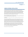
Four antenna elements are used for mobile operation. At frequencies below 500 MHz,
magnetically mounted quarter wave whips are used. These antennas must provide a good
coupling to the ground plane, and must be of exactly the same type. It is especially important
that the coaxes used have the same length. Doppler Systems antennas DDF7061 and 7062
use the same magnetic mount base and cover the frequency ranges 88-136 and 136-500
MHz respectively. Cut the whips to resonance using the chart provided with the antennas and
space them approximately 1/4 wavelength apart on the car’s roof.
Note: To avoid damage to the input circuitry used in the RF summer, touch the antenna ground
plane before attaching the whips to the magnetic mounts.
It is important that the vehicle provides at least 1/4 wavelength of ground plane outboard of
the antennas.
Place the RF summer (DDF7080) on the car with the cables oriented towards the rear of the
car. Connect the magnetic mount antenna cables to the corresponding TNC connectors on
the RF summer. (That is, the left front antenna to the left front connector, etc.) Locate the
summer near the back of the car (the lid of the trunk) so that the magnetic mount antenna
cables do not have excessive slack. Secure the four antenna cables together with nylon ties so
that they are not free to move around and touch the antenna elements. Route the control
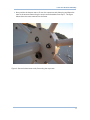
and RF cables through a rear window. For mobile operation in the 700-1000 MHz band,
antenna DDF7064 should be mounted directly on top of the RF summer. This antenna
provides an extended ground plane, a wind shroud, and four stub type antennas built into
TNC connectors. Place the assembled RF summer/antenna in the center of the car roof. Be
sure to use the safety strap provided with the DDF7064 antenna.
The photos below show typical installations.
5
Doppler MPT Users Manual
Revision A
Figure 1: VHF Mobile Antenna Installation
Figure 2: THF Mobile Antenna Installation
6
7
Chapter 4
FIXED SITE ANTENNA ASSEMBLY
Fixed site antennas are shipped unassembled. This section provides assembly instructions.
IN THIS CHAPTER
Antenna Mounting Location ........................................................................... 7
Single Band Antenna Installation .................................................................. 7
Two Band Antenna Installation .................................................................... 16
Three Band Antenna Installation ................................................................. 18
ANTENNA MOUNTING LOCATION
For optimum results it is necessary to mount the fixed site antenna as high as possible above
the average terrain. It is also required that the antenna be mounted at the top of any
metallic structure (tower) so that there is no metal in the antenna pattern. Do not mount the
antenna near any transmitting antenna. Serious damage can occur if large RF fields are
applied to the antenna. See the application note “In-band Interference from a Nearby
Transmitter” available on our web site www.dopsys.com for more information.
SINGLE BAND ANTENNA INSTALLATION
This section details the assembly of a single band fixed site antenna. The photographs are
for a VHF antenna but all the antennas use identical mounting hardware.
MOUNTING THE MAST TO THE ANTENNA
All of the antenna assemblies come with a bottom mast, an antenna frame, and antenna
elements.
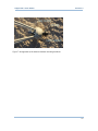
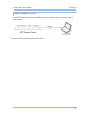
At the base of the antenna frame there are 5 longer screws protruding from the bottom
connector plate as shown in the photo below. Remove these screws and lockwashers. Do
not remove the 3 other screws.
7
Doppler MPT Users Manual
Revision A
Figure 3: Remove the longer cap screws to install the lower mast
8
Fixed Site Antenna Assembly
Next position the bottom mast to fit over the connectors and drain plug and fasten the
mast to the antenna frame using the screws and lockwashers from step 1. The figure
below shows the mast connected to the frame.
Figure 4: Secure the lower mast to the frame using the cap screws
9
Doppler MPT Users Manual
Revision A
ATTACHING THE BOTTOM MAST TO YOUR MAST
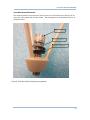
The fixed site antennas are furnished with a mast clamp for installation on a pipe or pole.
The diameter of the pipe or pole can be between 1.25 in. and 3.5 in. The figure below shows
how the mast clamp is installed.
Figure 5: Attach the lower mast to your mounting mast with the mast clamp
10
Fixed Site Antenna Assembly
ATTACHING THE CABLES
Unroll the control and coax cables being careful not to damage the ferrites or to crimp the
coax. Be careful to keep the connectors clean from dirt. Fasten the control cable by aligning
the key and turning the outer locking ring until it just meets the red line on the mating
connector. Fasten the TNC connector until it is tight. Use the supplied cable ties to fasten the
cables to the masts.
At this point the assembly should look similar to the photo below.
Figure 6: VHF antenna frame mounted on mast
ATTACHING THE ELEMENTS
Four Wire Biconical Antennas
The antenna elements are mounted to baluns at the end of the frame arms using an o-ring, a
5/16-24 cap screw, and a lock washer. The arrangement of the hardware is shown in the
photo below.
11
Doppler MPT Users Manual
Revision A
Figure 7: Arrangement of the antenna element mounting hardware
12
Fixed Site Antenna Assembly
Three Wire Biconical Elements
The antenna elements are mounted to baluns at the end of the frame arms using a 5/16-24
cap screw, a flat washer and a rubber washer. The arrangement of the hardware is shown in
the photo below.
Cap Screw
Flat Washer
Rubber Washer
Figure 8: Three Wire Element Mounting Arrangement
13
Doppler MPT Users Manual
Revision A
Thread the cap screw into the balun being careful not to cross thread the screw. Tighten the
cap screw until the lock washer is fully compressed. Do not over tighten the cap screw or the
brass threads in the balun may be stripped. Mount all sixteen elements. Align the biconical
elements so that all elements are symmetric. The photo below shows two elements
connected to the balun.
Figure 9: Antenna element mounted on the balun
14
Fixed Site Antenna Assembly
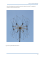
After all the elements are attached the antenna is ready to be erected. The assembled
antenna will look like the photo below.
Figure 10: Fully Assembled VHF Antenna
15
Doppler MPT Users Manual
Revision A
TWO BAND ANTENNA INSTALLATION
To assemble the two band antenna perform the steps detailed above; however, before
attaching the antenna elements install the connecting mast and cables. The connecting mast
is installed similarly to the base mast using the 5 longer screws and lock washers at each end.
When installing the coaxial cable make sure the end of the cable with the most ferrite beads
is connected to the lower antenna. The photo below shows the connecting mast with the
connecting cables attached to the top of the VHF antenna.
Figure 11: Connecting mast and cables installed for two antenna installation
16
Fixed Site Antenna Assembly
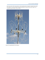
Next connect the UHF antenna frame to the coupling mast, connect the cables, fasten them
with cable ties, and then install the antenna elements on both VHF and UHF frames. The
completed antenna stack is shown below.
Figure 12: Assembled UHF-VHF Antenna
17
18
THREE BAND ANTENNA INSTALLATION
Follow the steps above to install the three element antenna and simply install the third
antenna using the short connecting mast supplied.
Figure 13: UHF Antenna Frame Installed on Mast
18
Fixed Site Antenna Assembly
Figure 14: UHF to THF mast with cables
19
Doppler MPT Users Manual User's Guide
Figure 15: THF Antenna Frame Installed
20
Fixed Site Antenna Assembly
There are two styles of THF elements. One style of elements mount similar to the other
elements except that they have longer cap screws. The other style shown in Figure 16 below
have a rubber washer installed to preload the elements and to keep moisture out of the
threads. Do not over tighten the elements or you may strip the brass inserts in the balun.
Figure 16: THF Element mounting hardware
21
Doppler MPT Users Manual User's Guide
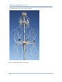
The final assembly will look like the photo below.
Figure 17: Assembled THF-UHF-VHF Antenna
22
Chapter 5
DDF7001 PROCESSOR CONNECTIONS
The DDF7001 processor requires a 12 V power supply, a loud speaker or headphones, a
receiver, and a Windows based computer. This section will detail the wiring and setup of the
DDF7001 processor for the various supported receivers, GPS receivers, and the compass. The
figure below identifies the various DDF7001 connectors.
Figure 18: DDF7001 Connectors
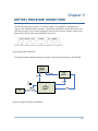
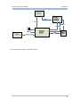
The following block diagrams illustrate a number of typical configurations for the DDF7001.
Figure 19: Single Fixed Site DF Installation
23
Doppler MPT Users Manual
Revision A
Figure 20: Direction Finder with RS232 receiver
24
Chapter 5 DDF7001 Processor Connections
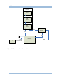
Figure 21: Single Antenna Fixed Site System with LAN Connection
25
Doppler MPT Users Manual
Revision A
DDF7095
THF
Antenna
Control
Coax
UHF
Antenna
Control
Coax
VHF
Antenna
Coax
USB
Receiver
Control
Audio
12VDC
PC
DF
Processor
DDF7001
USB
Crossover Cable
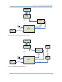
Figure 22: Three Antenna Fixed Site Installation
26
Chapter 5 DDF7001 Processor Connections
Mag Mounted
Antennas
Mag Mounted
Summer
DDF7080
Coax
Control
USB
Receiver
Audio
USB
DF
Processor
DDF7001
12VDC
Laptop
Crossover Cable
Figure 23: Basic Mobile Installation for Homing
Mag Mounted
Antennas
Mag Mounted
Summer
GPS
Coax
USB
Receiver
Control
RS232
Audio
USB
Laptop
12VDC
Crossover
Cable
USB-toSerial
DF
Processor
USB
Figure 24: Mobile Installation with GPS
27
Doppler MPT Users Manual
Revision A
IN THIS CHAPTER
Power and Speaker Connection ................................................................... 28
Receiver Connection ......................................................................................... 28
Computer Connection ..................................................................................... 30
NMEA Devices..................................................................................................... 33
POWER AND SPEAKER CONNECTION
A power and speaker cable is furnished with the DDF7001. The speaker output supports a
standard 8 ohm speaker. The unit is to be powered with an 11 - 14 V dc source. A schematic
of the power cable is shown below.
1
2
CON282
CAB171 (AWG22 GRN)
CAB172 (AWG22 YEL)
Twisted pair
SPKRhigh
SPKRlow
4
3
CON282 is Kobicon 16PJ225-EX
3.5mm mono inline jack.
5 ft end to end
View from Wiring End.
2
1
CON271/CON264
Red
CON212
2
1
CAB116 (AWG20 RED)
CAB117 (AWG20 BLK)
Twisted pair
+12VDC
Ground
Black
CON212 is Anderson PP15
power pole connector pair.
CON271 is Molex 39012045 receptacle.
CON264 are Molex 39000182 female terminal.
Figure 25: Power and Speaker Connections
As shipped, the audio output is configured for a single ended drive with the SPKRlow at
ground. If desired, the output may be reconfigured for bridge drive by moving the jumpers
on headers J13 and J14 to pins 2-3 instead of pins 1-2. The advantage of bridge drive is that
the power output is doubled, but the disadvantage is that approximately 2.5 VDC is present
on both SPKRhigh and SPKRlow and these leads must be kept isolated from ground. J13 and
J14 are located adjacent to the input power connector inside the DDF7001 processor.
RECEIVER CONNECTION
The receiver cable supplied with the DDF7001 is connected to the 6 pin connector labeled
Receiver. The phone plug on the end of this cable connects to the external speaker output of
the receiver. This input is DC isolated from ground so either a single ended or a bridge type
receiver audio output may be connected to the DDF7001. The input impedance is 10 ohms as
supplied. However, if you need a high impedance input, remove the jumper on J1 adjacent to
the receiver connector inside the DDF7001 processor.
28
DDF7001 Processor Connections
If your receiver has an RSSI analog, connect it to the blue wire, RSSI Input, with the white wire
grounded to the receiver. Additionally, you must connect the coaxial cable from the DF
antenna to the receiver antenna input.
RSSIinput
Ground
CAB170 (AWG22 BLU)
TWISTED
PAIR
CAB354 (AWG22 WHT)
6
5
4
View from Wiring End.
5 ft end to end
3
2
1
CON270/264
1
Audhigh
2
Audlow
CON281 (3.5mm)
CON281 is Kobicon 171-3235-EX
3.5mm mono plug.
TWISTED
PAIR
CAB355
(AWG22ORG)
CAB302
(AWG22VIO)
CON270 is Molex 39012065 receptacle.
CON264 are Molex 39000182 female terminals.
Figure 26: Receiver Connections
RECEIVER CONTROL
For the USB receivers connect the USB cable provided with your receiver to either of the USB
host ports on the DDF7001. For receivers that require a serial port you need to connect a
USB-to-Serial converter to one of the USB host ports and then connect the receiver to the
serial port. See the USB-to-Serial Converter section of this manual for further information.
29
30
COMPUTER CONNECTION
The DDF7001 can be connected to a network via a network hub or switch, or it can be directly
connected to the computer's network interface.
CONNECTING TO A NETWORK
To connect the DDF7001 to a network simply connect a standard CAT5 or CAT6 network
cable to the DDF7001 and to a switch, hub, or router on your network as depicted in the
figure below.
Figure 27: Connection into a network with a switch, hub, or router
30
DDF7001 Processor Connections
The Ethernet software in the DDF7001 ships with a DHCP client enabled, so if connected to a
network that supports DHCP, the DDF7001 will obtain an IP address from the DHCP server.
Once it has done this it begins broadcasting its IP address on the network as a UDP broadcast
message on port 9007.
This message is broadcast once every 2 seconds.
A Windows based program, Doppler DF Discover, is provided with the DDF7001 unit and will
display the IP address, the port number and the MAC address of the device as shown below.
Note the IP address because it is used to connect the browser and the Telnet interface to the
DDF7001. The latitude and longitude fields will be filled in if a GPS is connected to the
direction finder.
Figure 28: Doppler DF Discover will display all direction finders connected on a LAN
31
Doppler MPT Users Manual
Revision A
CONNECTING DIRECTLY TO A PC
The DDF7001 may also be connected directly to the computer using a crossover cable as
shown below.
Figure 29: Direct connection with crossover cable
32
DDF7001 Processor Connections
The DDF7001 is shipped with a default IP address of 10.0.0.100. If you are going to connect it
directly to your computer you must set your computer TCP/IP properties as shown in the
Figure below. Once it is connected you can use the web server or the Telnet interface to
change the IP address and the IP port number.
Figure 30: Network Interface Setup in Windows
33
Doppler MPT Users Manual User's Guide
Chapter 6
CONNECTING DEVICES TO THE DDF7001
34
Chapter 6 Connecting Devices To the DDF7001
The DDF7001 has two USB ports that enable the user interface a variety of devices to the
direction finder. The following devices are supported
ICOM R1500 Receiver
ICOM R2500 Receiver
AOR SR2200 Receiver
IO Gear GUC232A single port USB-to-Serial Adapter
USB Gear USBG-4X-RS232 4 port USB-to-Serial Adapter
USB Gear CA-232-1MB single port USB-to-Serial Adapter
EasySYNC USB2-H-1004 4 port USB-to-Serial Adaptor
EasySYNC ES-U-1001-B10 1 port USB-to-Serial Adaptor
Doppler Systems DDF6074 GPS Receiver (with serial adapter)
Doppler Systems DDF6075 Compass (with serial adaptor)
Doppler Systems DDF7057 Self Test Generator (with serial adaptor)
Doppler Systems DDF7056 Yaw Rate Sensor (with serial adaptor)
AOR AR8600 Receiver (with serial adaptor)
AOR AR5000 Receiver (with serial adaptor)
ICOM R8500 Receiver (with serial adaptor)
IN THIS CHAPTER
USB-to-Serial Converters ................................................................................ 36
NMEA Devices..................................................................................................... 36
USB Receivers ...................................................................................................... 37
Serial Receivers ................................................................................................ 361
Use of Receivers Not Supported by the Firmware ............................. 361
35
36
USB-TO-SERIAL CONVERTERS
USB-to-Serial converters are used for
interfacing serial receivers like the ICOM R8500 or AOR AR5000
connecting NMEA based devices such as a GPS receiver or a compass
connecting any serial device to the DDF7001
The DDF7001 supports up to a 4 port Prolific or FTDI chip set based USB-to-serial converters.
It is best to connect the converter prior to powering the DDF7001. Once the converter is
detected by the USB driver the MPT UI program can be used to configure the serial ports.
The ports will default to the NMEA mode if no other selection is made.
RECEIVER
If a serial receiver is selected port 0 will be configured for that receiver. This can be
overridden using the MPT User Interface program to set the receiver port to any serial port.
For the receivers supported by the DDF7001 the Set Frequency (0x0014), the Set Squelch
(0x0015), and the Set Rx Volume (0x0016) commands set the frequency, squelch, and receiver
volume. Other commands to the receiver can be passed to it using the Receiver pass through
command (0x0017).
NMEA
If a serial port is configured as an NMEA port, the $ at the beginning of the message is
stripped and the NMEA message is forwarded with its identifier.
GENERAL SERIAL DEVICE
If the serial port is configured as a general serial device then data is sent to the serial port
using the Serial Pass through (0x0026) command and data is received from the serial port via
the Serial Port Data (0x0026) response.
NMEA DEVICES
GPS receivers and compasses used with the DDF7001 output NMEA standard GGA, VTG, and
HDM messages. These devices are connected to the DDF7001 via a USB-to-serial converter.
See the USB-to-Serial Converter section of this manual for further information on using
USB-to-serial converters.
DDF7056 YAW RATE SENSOR
36
Connecting Devices To the DDF7001
The DDF7056 Yaw Rate Sensor is used to provide a faster update of the heading in mobile
applications where the vehicle is performing frequent turns. This device outputs an NMEA
message; however, its baud rate is 38.4 k. Therefore, the MPT User Interface software must
be used to set the baud rate to 38.4 k prior to using the yaw rate sensor.
USB RECEIVERS
The DDF7001 currently supports the ICOM R1500, ICOM R2500, and the AOR SR2200 USB
based receivers. The DDF7001 configures the receiver to receive narrow band FM
transmissions required for the direction finder to work properly. Currently only frequency,
squelch, and receiver volume setting is implemented; however scan commands are supported
within the Doppler SignalTrack and TargetTrack applications that make use of the receiver
command pass through feature.
SERIAL RECEIVERS
The DDF7001 currently supports the ICOM R8500, AOR AR8600, and the AOR AR500 RS232
commanded receivers. The DDF7001 configures the receiver to receive narrow band FM
transmissions required for the direction finder to work properly. Currently only frequency,
squelch, and receiver volume setting is implemented; however scan commands are supported
within the Doppler SignalTrack and TargetTrack applications that make use of the receiver
command pass through feature.
USE OF RECEIVERS NOT SUPPORTED BY THE FIRMWARE
It is possible to use receivers that are not supported by the direction finder’s firmware and
software. Any narrow band FM receiver or scanner can be used. Connect the audio output
(normally the external speaker jack) to the Audio Input of the direction finder (see Figure 26).
If you desire an S meter output from the direction finder firmware and the receiver has an
analog S-meter output connect the RSSI output of the receiver to the open leads on the
Receiver Connector (see Figure 23). After you make this connection you must calibrate the S
meter as described in the MPT Software User’s Manual.
Frequency, volume, and squelch settings must be made from the front panel of the receiver.
37
Doppler MPT Users Manual
Revision A
Chapter 7
CONFIGURING THE DIRECTION FINDER
The software configuration of the DDF7001 is described in the MPT Software User's Manual
and the help file that is installed with the MPT User Interface software. Refer to these
resources to learn how to adjust the direction finder settings.
38
Chapter 8 Interfacing to the DDF7001 Direction Finder
Chapter 8
INTERFACING TO THE DDF7001 DIRECTION
FINDER
This chapter is provided for the user that wants to develop their own software to interface
with the DDF7001 direction finder. It describes the command and response interface and the
audio streaming interface.
The RJ45 connector on the DDF7001 provides the Ethernet interface to the DDF7001
direction finder.
IN THIS CHAPTER
Using the Binary Serial Interface .................................................................. 39
Audio Interface ................................................................................................... 51
USING THE BINARY SERIAL INTERFACE
The binary serial interface is a telnet like interface that uses a TCP/IP connection to control
and extract data from the DDF7001 direction finder. When shipped the default static IP
address is 10.0.0.100 and the default IP port is 2101. Both the static IP address and the IP
port can be changed using either the web server or the binary serial interface. The MPT UI
software furnished with the DDF7001 utilizes binary serial interface.
39
Doppler MPT Users Manual
Revision A
COMMAND AND DATA STRUCTURE
Every DDF7001 command and the data coming from the DDF7001 conform to the data
structure as shown in the following table.
Byte #
Definition
Comments
0
0x02
STX indicates the start of the message
1
Length (LSB)
LSB of the total length of the message (from byte 3
through byte n)
2
Length (MSB)
MSB of the total length of the message
3
Message ID (LSB)
LSB of the message identifier
4
Message ID (MSB)
MSB of the message identifier
5-n
Message data
Any data sent with the message
n+1
CRC (LSB)
LSB of CRC check sum
n+2
CRC (MSB)
MSB of CRC check sum
n+3
0x03
ETX indicates the end of the message
* CRC is defined as CRC16 standard using 8005 for the generating polynomial see "A Painless
Guide to CRC Error Detection Algorithms". CRC is calculated on bytes 1 through n.
An example CRC algorithm written in the C language is shown in the listing below.
short CRCTable[] =
{
0x0000, 0xC0C1,
0x06C0, 0x0780,
0xC741, 0x0500,
0x0F00, 0xCFC1,
0xCE81, 0x0E40,
0xC841, 0xD801,
0x18C0, 0x1980,
0xDF81, 0x1F40,
0xDD01, 0x1DC0,
0x17C0, 0x1680,
0xD641, 0xD201,
0xF001, 0x30C0,
0x3180, 0xF141,
0x3740, 0xF501,
0x35C0, 0x3480,
0x3E80, 0xFE41,
0xFA01, 0x3AC0,
0xE8C1, 0xE981,
0xC181, 0x0140, 0xC301, 0x03C0, 0x0280, 0xC241, 0xC601,
0xC5C1, 0xC481, 0x0440, 0xCC01, 0x0CC0, 0x0D80, 0xCD41,
0x0A00, 0xCAC1, 0xCB81, 0x0B40, 0xC901, 0x09C0, 0x0880,
0xD941, 0x1B00, 0xDBC1, 0xDA81, 0x1A40, 0x1E00, 0xDEC1,
0x1C80, 0xDC41, 0x1400, 0xD4C1, 0xD581, 0x1540, 0xD701,
0x12C0, 0x1380, 0xD341, 0x1100, 0xD1C1, 0xD081, 0x1040,
0x3300, 0xF3C1, 0xF281, 0x3240, 0x3600, 0xF6C1, 0xF781,
0xF441, 0x3C00, 0xFCC1, 0xFD81, 0x3D40, 0xFF01, 0x3FC0,
0x3B80, 0xFB41, 0x3900, 0xF9C1, 0xF881, 0x3840, 0x2800,
40
Interfacing to the DDF7001 Direction Finder
0x2940, 0xEB01,
0x2D00, 0xEDC1,
0xEC81, 0x2C40,
0x2640, 0x2200,
0xE2C1, 0xE381,
0x6180, 0xA141,
0x6300, 0xA3C1,
0x65C0, 0x6480,
0xA441, 0x6C00,
0xAA01, 0x6AC0,
0x6B80, 0xAB41,
0x7940, 0xBB01,
0x7BC0, 0x7A80,
0xBC81, 0x7C40,
0xB401, 0x74C0,
0xB2C1, 0xB381,
0x7340, 0xB101,
0x9301, 0x53C0,
0x5280, 0x9241,
0x5440, 0x9C01,
0x5CC0, 0x5D80,
0x9B81, 0x5B40,
0x9901, 0x59C0,
0x8BC1, 0x8A81,
0x4A40, 0x4E00,
0x4400, 0x84C1,
0x8581, 0x4540,
0x8341, 0x4100,
0x81C1, 0x8081,
};
// DESCRIPTION:
//
// INPUT:
// INPUT:
0x2BC0, 0x2A80, 0xEA41, 0xEE01, 0x2EC0, 0x2F80, 0xEF41,
0xE401, 0x24C0, 0x2580, 0xE541, 0x2700, 0xE7C1, 0xE681,
0x2340, 0xE101, 0x21C0, 0x2080, 0xE041, 0xA001, 0x60C0,
0xA281, 0x6240, 0x6600, 0xA6C1, 0xA781, 0x6740, 0xA501,
0xACC1, 0xAD81, 0x6D40, 0xAF01, 0x6FC0, 0x6E80, 0xAE41,
0x6900, 0xA9C1, 0xA881, 0x6840, 0x7800, 0xB8C1, 0xB981,
0xBA41, 0xBE01, 0x7EC0, 0x7F80, 0xBF41, 0x7D00, 0xBDC1,
0x7580, 0xB541, 0x7700, 0xB7C1, 0xB681, 0x7640, 0x7200,
0x71C0, 0x7080, 0xB041, 0x5000, 0x90C1, 0x9181, 0x5140,
0x9601, 0x56C0, 0x5780, 0x9741, 0x5500, 0x95C1, 0x9481,
0x9D41, 0x5F00, 0x9FC1, 0x9E81, 0x5E40, 0x5A00, 0x9AC1,
0x5880, 0x9841, 0x8801, 0x48C0, 0x4980, 0x8941, 0x4B00,
0x8EC1, 0x8F81, 0x4F40, 0x8D01, 0x4DC0, 0x4C80, 0x8C41,
0x8701, 0x47C0, 0x4680, 0x8641, 0x8201, 0x42C0, 0x4380,
0x4040
Calculates the CRC-16 value of a buffer of data
*data
NumBytes
Pointer to the data buffer
Number of bytes to read for CRC
short CalcCRC16 (char *Data, short NumBytes)
{
unsigned int
i;
u8 CRCLoByte;
u16 CRCResult;
CRCResult = 0x0000;
for (i = 0; i < NumBytes; i++)
{
CRCLoByte = (u8)(CRCResult & 0x00FF);
CRCResult = ((CRCResult & 0xFF00) >> 8) ^ CRCTable[*Data++ ^
CRCLoByte];
}
return CRCResult;
}
41
Doppler MPT Users Manual
Revision A
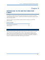
COMMANDS
The following table defines the commands that can be sent to the DDF7001. The DDF7001
responds by echoing back the command with the value that was accepted by the DDF7001.
If the DDF7001 did not accept the command then nothing will be echoed back. Items
marked in bold are the default settings. All data is sent in little Endian format (lowest order
byte sent first)
42
43
Command
Command
Data
Name
Number
Length
Range
Comments
Sweep Rate
0x0001
byte
0-4
0 = 0, 1=250,2=500.3=1000,4=2000
Averages
Attenuator
0x0002
byte
1-20
Default is 2
0x0003
byte
0–1
0 = off, 1 = on
Audio Volume
0x0004
byte
0 – 96
0 = max volume, 96 = muted, default 20
Reserved for future use
0x0005
Receiver Type
0x0006
byte
0–4
0 = ICOM R8500
1 = ICOM PCR1500
2 = ICOM PCR2500
3 = AOR AR8600
4 = AOR AR5000
If the receiver requires a serial port and no serial port has been
assigned for the receiver then serial port 0 will be assigned to
the receiver
Sample Time
0x0007
Reserved for future use
0x0008
Threshold
0x0009
short
10 – 10000
Sample time in ms Maximum value 1500 ms
Default 500 ms
short
10 – 10000
Sets the maximum separation of consecutive bearing
measurements that will be used in the bearing calculation.
Setting this number low will result in some missed bearings.
Setting it high will result in more false positives. Default 4000
43
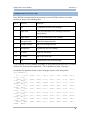
Doppler MPT Users Manual
Antenna
Revision A
0x000A
byte
0 = VHF
In Auto mode the antenna switches will be controlled by the
1= UHF
receiver frequency as shown below (receiver frequency must be
2 = THF
controlled by the direction finder)
3= Auto
100 < f < 250 MHz - VHF Antenna
250 ≤ f < 500 MHz – UHF Antenna
500 ≤ f < 1000 MHz – THF antenna
Reserved for future use
0x000B
Direction Cosines
0x000C
4 INT16
-10000 - 10000
Range is -1 to 1 (divide by 10000)
Each receiver has calibrated direction cosines. Typically the
user does not need to change these
Calibrate
0x000D
INT16
0 – 3599
Range is 0-359.9 (divide by 10)
Calibrate the bearing to a given angle
Identify Hardware
0x000E
0
Causes hardware version response
Identify Software
0x000F
0
Causes software version response
List Serial Ports
0x0010
0
Lists each serial port connected to the system and its parameters.
The serial ports correspond to USB-to-serial converters
connected to the DDF7001.
44
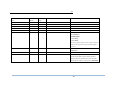
Interfacing to the DDF7001 Direction Finder
Configure Serial Port
0x0011
6 bytes
Byte 0 : port number (0 - 3)
The DDF7001 supports up to a 4 port USB-to-serial converter.
Byte 1 : Baud Rate
0 = 1200
1 = 2400
2 = 4800
3 = 9600
4 = 19200
5 = 38400
Byte 2 : Stop Bits
0=1
1 = 1.5
2=2
Byte 3 : Data Bits
0=7
1=8
Byte 4 : Parity
0 = none
1 = even
2 = odd
Assign Serial Port
0x0012
2 bytes
Byte 0 : port number
Port number 0 – 3
Byte 1 : device
0 = NMEA
1 = Receiver
2 = pass through
Pass through means all data flows from the serial port to the
Ethernet port and vice versa.
Send DF Settings
0x0013
0
Causes DF settings response
Set Frequency
0x0014
UINT32
0 – 2000000000 (2 GHz)
Hz
Set Squelch
0x0015
byte
0 – 255
Default 0
Set Rx Volume
0x0016
byte
0 – 255
Default 128
45
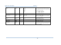
Doppler MPT Users Manual
Revision A
Receiver Pass Through
0x0017
Various
Sweep
0x0018
byte
Sends command directly to receiver
Nibble 0 : Direction
0 = CW
Manual command to start the sweep
Used in factory testing. Not recommended for use by user.
1 = CCW
Nibble 1: Sweep State
0 = Sweep Off
1 = Sweep On
Calibrate S Meter
0x0019
byte
0–9
Callibrates S-meter to the level indicated. Works only with
receivers having an analog RSSI output
Filter
0x001A
Reserved for future use
0x001B
Hold Time
0x001C
byte
0 = Off, 1 = On
Enables or disables the audio filter that removes the antenna
sweep rate tone
byte
Hold time in seconds
Time DF holds the bearing calculation
DF Sends 360 when hold time expires
Default 5 seconds
DHCP
0x001D
byte
0 = do not use DHCP
1 = use DHCP
IP Address
0x001E
4 bytes
Sets the IP Address
If using DHCP this sets the default IP address.
Default 10.0.0.100
IP Gateway
0x001F
4 bytes
Sets the IP Gateway
Default 255.0.0.0
IP Subnet Mask
0x0020
4 bytes
Sets the IP Subnet Mask
Default 10.0.0.1
IP DF Port
0x0021
UINT16
Sets the port for the DF communications
Default 2101
Send Rx Settings
0x0022
0
Gets the frequency, volume, and squelch settings
Set to Default
0x0023
0
Sets all parameters to their default values (IP
Reset Processor
0x0024
0
Reserved
0x0025
parameters excluded)
Restarts the processor
(All ip connections will be terminated)
46
Interfacing to the DDF7001 Direction Finder
Serial Pass Through
0x0026
Various
byte 0: port Number
remaining bytes serial port data
Send Serial Number
0x0027
0
Stream Audio
0x0028
UINT16
Sends the serial number of the unit
Port number to stream audio to
0 = disable streaming
Streaming Audio Squelch
0x0029
UINT16
Compress Audio
0x002A
UINT8
Audio must exceed squelch level in order for audio
Default 50
to be streamed
0 = no compression
1 = A law compression
47
48
RESPONSES
With the exception of commands that specifically ask for data to be sent the response to a
command is that it will echo the data back in the exact format it was sent with the actual
settings of the DDF7001.
The following table defines responses from the DDF7001
48
49
Response Name
Response Number
Format
Comments
Bearing Message
0x0000
ASCII
Comma delimited string
Bearing (0-359.9),
S meter (0-255),
Number of Averages (0-20),
Audio Level (0-2047)
UTC Timestamp (if GPS receiver is connected)
Identify Hardware
0x000E
ASCII
String will be of the form major version .minor version
Identify Software
0x000F
ASCII
String will be of the form major version .minor version
Direction Cosines
0x000C
16 Bytes
Bytes 0-3 10000 * cos theta CW
Bytes 4-7 10000 * sin theta CW
Bytes 8-11 10000 * cos theta CCW
Bytes 12-15 10000 * sin theta CCW
All in Little-Endian format
List Serial Ports
0x0010
ASCII
Comma separated list of the connected port data
Port Number (0-3),
Status,
Baud Rate (1200 – 38400),
Data bits (7 or 8)
Stop bits (1, 1.5, or 2
Parity (N = None, O=Odd, E=Even, M=Mark, S=Space,
Function (NMEA,RECEIVER,PASS THROUGH)
Each set of port parameters is separated by a carriage return character
Send DF Settings
0x0013
ASCII
Settings will be sent as a block of ASCII data with each setting having the following format
Cmd number,setting<CR>
S Meter Cal Constants
0x0019
ASCII
Two comma separated strings representing the slope and intercept constants in exponent format (e.g. 1.23e1,1.045e3)
Receiver Data
0x0017
Bytes
Data received from the receiver that is passed through the DDF7001
49
Doppler MPT Users Manual
RX Settings
0x0022
Revision A
ASCII
Settings will be sent as a block of ASCII data with each setting having the following format
Cmd number,setting<CR>
Serial Port Data
0x0026
Bytes
Data from the serial ports
Byte 0 = port number
Remaining bytes is the message
Serial Number
0x0027
ASCII
Serial number
50
51
AUDIO INTERFACE
The DDF7001 digitizes the receiver audio and can stream it via UDP. Once a TCP/IP
connection is made the controller sends a Stream Audio (0x0028) command to the DDF7001
signaling the DDF7001 as to which port to use to stream the audio. Once this command is
received the DDF7001 will stream the audio when the audio level exceeds the audio squelch
threshold. This threshold can be set via the command interface.
Compression
The audio can be sent compressed or uncompressed depending on the preference of the
programmer. When compressed A-law compression is used. The algorithm for
decompressing the audio is shown below. If uncompressed audio is streamed then a
maximum of 4 connections is allowed. Compressed audio allows up to 8 streaming
connections.
short decode(byte alaw)
{
//Invert every other bit, and the sign bit (0xD5 = 1101 0101)
alaw ^= 0xD5;
//Pull out the value of the sign bit
int sign = alaw & 0x80;
//Pull out and shift over the value of the exponent
int exponent = (alaw & 0x70) >> 4;
//Pull out the four bits of data
int data = alaw & 0x0f;
//Shift the data four bits to the left
data <<= 4;
//Add 8 to put the result in the middle of the range (like adding a
half)
data += 8;
//If the exponent is not 0, then we know the four bits followed a 1,
//and can thus add this implicit 1 with 0x100.
if (exponent != 0)
data += 0x100;
/* Shift the bits to where they need to be: left (exponent - 1) places
* Why (exponent - 1) ?
* 1 2 3 4 5 6 7 8 9 A B C D E F G
* . 7 6 5 4 3 2 1 . . . . . . . . <-- starting bit (based on exponent)
* . . . . . . . Z x x x x 1 0 0 0 <-- our data (Z is 0 only when
exponent is 0)
* We need to move the one under the value of the exponent,
* which means it must move (exponent - 1) times
* It also means shifting is unnecessary if exponent is 0 or 1.
*/
if (exponent > 1)
data <<= (exponent - 1);
return (short)(sign == 0 ? data : -data);
}
51
Doppler MPT Users Manual User's Guide
INDEX
A
S
ANTENNA MOUNTING LOCATION • 7
ATTACHING THE BOTTOM MAST TO A
YOUR MAST • 10
ATTACHING THE ELEMENTS • 11
AUDIO INTERFACE • 50
SINGLE BAND ANTENNA INSTALLATION •
7
C
COMMAND AND DATA STRUCTURE • 39
COMMANDS • 41
COMPUTER CONNECTION • 30
CONFIGURING THE DIRECTION FINDER •
37
CONNECTING DEVICES TO THE MPT • 33
F
T
THREE BAND ANTENNA INSTALLATION •
18
TWO BAND ANTENNA INSTALLATION • 16
U
USB RECEIVERS • 35, 36
USB-TO-SERIAL CONVERTERS • 30, 35
USB-TO-SERIAL CONVERTERS • 35
USING THE BINARY SERIAL INTERFACE •
38
W
FIXED SITE ANTENNA ASSEMBLY • 7
I
INTERFACING TO THE MPT DIRECTION
FINDER • 38
INTRODUCTION • 2
M
MOBILE ANTENNA INSTALLATION • 4, 5
MOUNTING THE MAST TO THE ANTENNA
•7
MPT PROCESSOR CONNECTIONS • 23
P
POWER AND SPEAKER CONNECTION • 29
R
RECEIVER CONNECTION • 29
RESPONSES • 47
52
WARRANTY INFORMATION • 1


![G2 Decoder [obsolete] Second Generation User Manual](http://vs1.manualzilla.com/store/data/005963661_1-2c18e92993151caf68904a7a924089ff-150x150.png)