1
Warranty Information
This warranty covers substantial defects in materials and workmanship in the G2 decoder.
What This Warranty Does Not Cover
This warranty does not cover any problems which result from improper installation, modifications,
battery polarity reversal, improper operation, leaking batteries, excessive battery voltages,
excessive motor current draw, connections to 3rd party circuit boards, abuse, accidents, or acts of
God such as excessive heat, floods, damage caused by exposure to moisture and rain, lightning,
earthquakes, volcanic events, tidal waves or hurricanes.
Warranty Duration
The coverage of this warranty lasts for 90 days. After this period, standard repair rates apply.
Depending on the problem, CVP reserves the right to repair or replace.
The AirWire900® 2nd Generation Decoder
The G2™ Decoder
G2 Decoder Layout And Terminal Identification . . . . . . . . . . . . . . . . . . . . . . . . . . . . . . . . 2
Installation Considerations and Absolute Maximum Ratings. . . . . . . . . . . . . . . . . . . . . . . 3
Battery Wiring And Battery Polarity Verification. . . . . . . . . . . . . . . . . . . . . . . . . . . . . . . . 4
Single Battery And Parallel Battery Hookup . . . . . . . . . . . . . . . . . . . . . . . . . . . . . . . . . . . 5
Series Battery Connection And Split Battery Hookup . . . . . . . . . . . . . . . . . . . . . . . . . . . . 6
G2 To Motor Hookup Diagrams . . . . . . . . . . . . . . . . . . . . . . . . . . . . . . . . . . . . . . . . . . . . 7, 8
Repairs and Returns
If you purchased your G2 decoder from one of our AirWire900 dealers, please call them first. They
are your best and quickest for answers to questions about G2 decoder. They are also experts in
installation and offer such services should it be required.
If you purchased your G2 decoder directly from CVP Products, you may call the office number
below.
If you are asked to return an item to CVP for service, you must follow the instructions on the website
under service and support and you must obtain an RMA. There you will find the street address plus
other helpful tips about sending packages to CVP Products. Do not send items to us for repair
without first obtaining authorization.
Installation Accessories
Order direct from CVP. Prices do not include shipping or applicable sales taxes.
Split Board Kit with 3 inch flex cable
[ SFX3 ]........................................... $13.95
Split Board Kit with 6 inch flex cable
[ SFX6 ]........................................... $13.95
These kits includes the special very thin flat flex cable and instructions. It allows the G2 decoder circuit board to
be split in to two parts: the radio receiver and the motor driver. The flex cable plugs into the the existing
connectors already mounted on the board. No soldering required. The thin flex cable is already pre-stripped and
tinned ready for use to reconnect the two halves.
Range Extender Kit
[REK1] ........................................... $14.95
Includes 36 inches of premium quality, ultra-flexible, shielded cable for motor wiring, 24 inches of 2-conductor,
tightly twisted #18AWG wire for battery connections and motor brush filter capacitors and two different values
of motor driver limit resistors. When installed as described in the accompanying manual, the decoder reception
range can be significantly extended.
Fuse Kit
[ FK9 ] ............................................. $ 7.95
Includes in-line fuse holder with 18” wire leads, two 10A slo-blo fuses and hookup diagram. Provides
catastrophic protection for the battery and motor driver.
Rigid Antenna, and Cable
[ CA ]............................................... $ 19.95
Includes 5 inch rigid antenna attached to 9 inches of RG174 coax cable. Cable solders to the AW9D10 board in
place of the standard wire antenna. Allows antenna to be placed on top of car or locomotive for improved very
long range reception.
Dome Antenna, and Cable
[ DCA ]............................................. $25.95
Low profile “dome” antenna. The dome is attached to 9 inches of RG174 coax cable and plug. The plug is
removed and the cable solders to the receiver board in place of the standard wire antenna. It allows for an external
antenna to be placed on top of a car or locomotive for improved reception.
120 Watt Adjustable DC Power Supply
[ DCPS120 ].....................................$ 55.00*
* Not sold through dealers. Available direct from CVP Products.
All prices shown are suggested retail prices and are subject to change
without notice. See website for the latest price list and ordering information.
B
May 2011 r11a
A full color version of this booklet is available on the CVP website
CVP Products P.O. Box 835772 Richardson, TX 75083-5772
972-238-9966 10AM- 4PM Central Time, Weekdays
www.cvpusa.com
G2 Headlamp Wiring . . . . . . . . . . . . . . . . . . . . . . . . . . . . . . . . . . . . . . . . . . . . . . . . . . . . . 9, 10
Using a Remote Frequency Selector. . . . . . . . . . . . . . . . . . . . . . . . . . . . . . . . . . . . . . . . . . 10
Frequency Selector Settings . . . . . . . . . . . . . . . . . . . . . . . . . . . . . . . . . . . . . . . . . . . . . . . . 11
Using The Auxiliary DCC Booster Output With Sound Decoders. . . . . . . . . . . . . . . . . . . 12-16
Simplified Quick Checkout Of Installation . . . . . . . . . . . . . . . . . . . . . . . . . . . . . . . . . . . . 17
Resetting Decoder To Factory Defaults . . . . . . . . . . . . . . . . . . . . . . . . . . . . . . . . . . . . . . . 18
Simplified Troubleshooting and Operating Notes . . . . . . . . . . . . . . . . . . . . . . . . . . . . . . . 19
Fault Protection, Annunciation, Reset . . . . . . . . . . . . . . . . . . . . . . . . . . . . . . . . . . . . . . . . 20
Operating Tips. . . . . . . . . . . . . . . . . . . . . . . . . . . . . . . . . . . . . . . . . . . . . . . . . . . . . . . . . . . 21
Activating and Using Cruise Control . . . . . . . . . . . . . . . . . . . . . . . . . . . . . . . . . . . . . . . . . 22, 23
Fine Tuning Locomotive Performance And Operation. . . . . . . . . . . . . . . . . . . . . . . . . . . . 24
Customizing Decoder Performance With CVs . . . . . . . . . . . . . . . . . . . . . . . . . . . . . . . . . . 25-29
List of All G2 Decoder Configuration Variables . . . . . . . . . . . . . . . . . . . . . . . . . . . . . . . . 29
Batteries, Chargers and Other Useful Information . . . . . . . . . . . . . . . . . . . . . . . . . . . . . . . 30-32
Managing Heat Buildup And Hot Climate Derating . . . . . . . . . . . . . . . . . . . . . . . . . . . . . 33, 34
Power Through The Rails - Some Considerations . . . . . . . . . . . . . . . . . . . . . . . . . . . . . . . 35
Warranty Information, Technical Support, Installation Accessories . . . . . . . . . . . . . . . . . Back
WARNING
NEVER connect the G2 decoder to any 3rd party lighting boards or other external
circuit boards. Failure of the lighting board and the G2 decoder is likely and this is
not covered by any warranty.
Need Help? Contact Your Dealer/Installer First!
Should you have any questions regarding AirWire or instllations, your dealer is your best source of
information, tips and techniques. Also, almost all dealers will do installations or can recommend good
installers. It might take a little more time cost a bit more, but you’ll be assured of an installation that
works and works well.
AIRWIRE
900
®
Contents
G2 Decoder - rev10
Shielded Cable
Test Diode
This Manual
G2, AirWire, AirWire900, the stylized AirWire name and the logo are registered trademarks of CVP Products. © 2011
1
G2 Decoder
Connections
8
7
6
5 4
Power
Indicator
3
#1
#2
#3
#4
#5
#6
#7
#8
2 1
8
7
6
5
4
3
2
1
Buzzer
Warning
The G2 wiring is different than the
original AWD10SS decoder. Failure to
correctly hookup the G2 decoder will
cause unusual operation or complete
failure.
2
TM3 - Battery and Motor Terminals
Battery Positive (+) Input
Motor Terminal A Out
Motor Terminal A Out
Motor Terminal B Out
Motor Terminal B Out
Ground for shielded cable
Ground for shielded cable
Battery Negative (-) Input
J1 Jumper
Normally, this jumper remains across the posts
and the Auxiliary DCC driver output voltage is
the same as the motor drive voltage.
If the jumper is removed, a lower voltage can be
used for the DCC output voltage and the lights.
The power source for the DCC voltage is hooked
up to TM2, pin 8 - see page 9.
TM2 - Function Outputs
#8
Lamp common plus
#7
Same as pin #8
#6
Rear Backup light
[CV60]
#5
Front Head light
#4
FnB Output [CV62]
#3
FnA Output [CV61]
#2
Auxiliary DCC Output B
#1
Auxiliary DCC Output A
The bracketed CV# is the configuration
variable that allows you to customize the
output. This is described in the CV
customization section.
Split Board Location
The closely spaced holes allow the board to
be cut apart for mounting in unusual spaces.
Split Board Sockets - SK2, SK1
Connect optional split-kit cable between SK1
and SK2 to join a split board.
Frequency Selector
Selects one of 8 operating frequencies. Must
match the frequency of the throttle.
TM1 - External Selector Switch Pads
An optional external frequency selector
switch may be connected here see page 10.
Antenna
The standard antenna is a short piece of
#18 gauge stranded wire. Do not cut or
change the length of the wire since this
will restrict the range. Best orientation is
perpendicular to pcb.
Power Through The Rails - Some Considerations
The G2 decoder is designed for battery powered operation. Although power can be supplied through
the rails, we do not recommended it. If you plan to use something other than batteries, consider the
following points before your final decision.
Clean wheels and clean track are mandatory if power is not supplied by batteries. Battery powered
outdoor locomotives never need to have wheels cleaned and never need to have the track cleaned.
Don’t let anybody fool you into thinking they never clean track. It is not always dirt that causes
problems. Sand, mud, bugs, leaves, grass and all other manner of detritus will cause track pickup
problems. If your friend has not cleaned track, don’t worry, they will have to eventually.
Electrical safety is compromised the moment you replace batteries with power derived from
household power and feed it onto the rails. Do you know about and how to use a Ground-FaultInterrupter? If not, stay with batteries - battery power is the safest form of power in the garden
railway.
Wiring the railroad becomes a long and boring chore. If you use battery powered locomotives, your
wiring job reduces down to connecting the decoder to the motor; simple and quick. There is no need
to worry about reverse-loops, turnout wiring, dead frogs, opposing point switch wiring, route control
wiring and the many other wiring requirements related to properly powering locomotives through
the rails.
However, if you insist, then here is the hook up diagram and the required external components to
allow the G2 decoder to draw DC power from the battery AND the rails. Don’t forget that the motor
must still be disconnected from the track pickups and wired directly to the decoder output.
To power the rails, use a well regulated DC power supply for best performance under varying load
conditions. If you are using 12V gel-cel batteries ONLY , then the DCPS120 power supply can
charge the gel-cel battery. Be sure and feed the DCPS120 from a GFI protected outlet. Set the
DCPS120 power supply to 15 volts. This will provide sufficient voltage to charge the lead-acid gelcell battery. This charging technique will not work for any other battery type.
Capacitor
2200uF/50V
Track
Pickups
AC 10 Amp
50V
Bridge
Rectifier
AC
+
10A/50V
Diode
12V
Gel-cel
1
+
+
8
Track Bus Wire - #10 AWG or Larger
DCPS120
Power Supply
All standard wiring requirements apply
including proper handling of reversing
loops, power blocking, and bus feeds to
each section of track. This is not a trivial
task!
The DCPS120 Power supply is a 120 Watt, adjustable DC power supply with
excellent load regulation. The output voltage is variable from 15V to 24V. It has built
in overload and short circuit protection. It is available direct from CVP Products and
the price is $55 not including shipping and handling.
35
Hot Climate Operation and Derating continued
Improve Air Flow
Although locomotives and cars have many openings for air to enter, the addition of more
vents on the bottom and in the roof will greatly aid heat removal. For diesels, consider
opening up the grid and radiator fan housings especially if they are simply cast on. Drill
additional holes in the floor. Also consider removing plastic windows, especially if the
locomotive is small and the decoder is in the cab. Small muffin fans, running on 12V will
help considerably providing there is room for them. Be sure and use low current fans, to
minimize the battery drain.
Lower The Battery Voltage
Since the power dissipated by the decoder is based on the motor current and battery
voltage, a lower voltage battery will significantly lower the maximum heat generated.
You’ll also find that the batteries last longer. Yes, the top speed will also decrease but not
by much. On hilly layouts, the use of multiple locomotives in a consist is much more
efficient than a single locomotive, running at maximum power, straining to make it up the
grade.
Derating Maximum Output Current In Hot Climates
High outdoor temperatures will result in hot interior temperatures even when there is good
airflow. The G2 output current is limited to a rather high value based on the temperature of
the drivers. If the drivers overheat, through excess motor current or because of a hot
interior, the devices will shut down to protect themselves.
A good rule of thumb is to derate the available current by about 1 Amp per 10 degrees of
temperature increase above 80 degrees. For example, if the outdoor temperature is 100
degrees, the maximum allowable current should be decreased by about 2-3 Amps. The
motor drive current should not exceed about 8 Amps under any conditions.
G2 Decoder Thermal Fault Clearing
Should the thermal overload protection trip on the motor drivers, turn off the power and
allow the drivers to cool. Once cool, the power can be turned on and operation resumed.
If the thermal protection trips on the DCC Auxiliary drivers, the buzzer will sound.
Resetting is automatic and does not require the power to be turned off. However, you
should improve the air flow since this is the decoder’s way of saying that it is too hot.
Chassis floor construction
Fair
Open grid fan grills
Don’t depend on small
openings to provide
ventilation
Better
Airflow In Modern Plastic Diesel Locomotives
34
Drill vent holes in floor
Before You Begin: Installation Considerations
Do Not Use The Locomotive’s Internal Circuit Boards - Do not attempt to use any of the loco’s
built-in circuit boards for wiring and connections especially to the motor. This is one of the most
common causes of decoder damage and or failure of the constant speed feature. Remove the boards
and install the motor wiring exactly as shown in this manual.
Battery Chemistry and Battery Selection - The more exotic the battery chemistry, the lighter and
smaller it will be compared to a gel-cel battery having the same energy capacity. However, unlike a
gel-cel, the new battery technologies are much more sensitive to poor charging. The battery will
also be much more expensive. The matching charger will also be more expensive. However, when
properly used and charged with an appropriated charger, the batteries will have a long lifetime.
The Li-ion and NiMH batteries can be purchased from an on-line store specializing in RC cars and
airplanes. Be sure to obtain the matching charger.
Fusing The Battery - always use a fuse in series with the battery. Large batteries can supply an
astonishing amount of energy into a short circuit. If small diameter wire is used and a short circuit
occurs, the wire will instantly become a heater element and melt the insulation from the wire.
Always Use a Power Switch Between Loco and The G2 - The use of a power switch will insure that
the battery is not discharged by the decoders. A second power switch is highly recommended
between any other decoders and the auxiliary DCC outputs.
Lower Battery Voltage Is Better - Lower voltages mean the motors and electronics run cooler.
There is also a remarkable increase in effective reception range since lower motor voltage results in
less electrical noise. For hilly railroads, consider the use of multiple locomotives on a train. Not only
will the batteries have a longer life, but the G2 decoder will run much cooler.
Motors Are Electrically Noisy - Use the included shielded wire to connect the decoder to the
motor(s).
Beware of Excessive Heat Buildup - The decoder should be placed in a location where it can
receive some airflow for the large transistors. These will become warm to very hot depending on the
battery voltage and motor current. Never cover the transistors or the board.
Antenna Location - The antenna should be vertical and can be bent such that it remains vertical if
the board is mounted on its side. Keep the antenna away from anything metal. Also, the antenna
should be kept away from motors and the battery wiring. For longer range, an optional longer
antenna is available. See the back page for ordering details.
Old AirWire Motor Filter Capacitors - The 10 ohm resistor and 0.1uF capacitor supplied with
CVP’s older AirWire Decoder are not necessary with the G2 and should not be used.
Incorrect operation of the constant speed feature will occur if there is
other circuitry, including lighting circuit boards, connected to the G2 motor terminals.
Only motors can connect to the G2 motor terminals.
G2 Decoder - Absolute Maximum Ratings
Maximum Input Battery Voltage . . . . . . . . . . . . . . 28 Volts DC
Minimum Input Battery Voltage. . . . . . . . . . . . . . . 10 Volts DC
Maximum Motor Output Current - Pulse . . . . . . . Internally Limited ~ 18A peak
Maximum Continuous Motor Output Current . . . ~ 8 Amps at 25°C @15V
Maximum DCC Auxiliary Output Current . . . . . . 3 Amps
Maximum Headlamp Output Current . . . . . . . . . . 1 Amp
Maximum FnA, FnB Output Current . . . . . . . . . . 1 Amp
3
Heat and Hot Weather Tips -Managing Heat Build-up!
Battery Wiring And Polarity Verification
Warning: Installation of the AirWire decoder does not require special tools. However, you
should be comfortable with soldering and have a general idea of how your locomotive is
wired, as it comes from the factory. If you are at all uneasy about these procedures, your
dealer can suggest installers who can do the job for you.
Each of the following sections describes the connection of various terminals on the G2
decoder. Use these diagrams as a generic guide to the connection of the G2 decoder to your
locomotive.
Use #18 AWG wire all battery connections. For improved radio reception, tightly twist two
differently colored wires together using an electric drill. Always use two different colors of
wire. All naked wires must be insulated with tape and/or heatshrink tubing. First, hook up all of
the battery minus wires. The battery negative wires are colored black. Next, hook up the
battery plus wires which are colored red.
Always include a power switch and a fuse in every installation. The power switch is used to
disconnect the battery from the locomotive. In some cases it is also used to select either the run
mode or the charging jack. A 10 cent fuse protects the battery against catastrophic failures
caused by improper wiring.
J1 Jumper Must Be Across Posts - Before testing polarity make sure J1 is
across the two posts.
J1
ON
Polarity Verification - one way to quickly end the life of the G2 decoder is to connect up the
battery with the plus and minus reversed. Included with the G2 decoder is a small polarity
testing diode that is used to verify that you have the plus and minus leads properly identified
before you connect them to the decoder.
TM3 is the large 8 pin terminal block on the end of the G2 board. Pin 8 is the top right pin when
the terminal block faces to the right as in the picture. Terminal strip references are shortened to
the terminal designator, either TM2 or TM3 and a specific pin number. For example, TM3-8 is
where the battery minus always connects. Before using the diode, first connect the battery
minus lead to the decoder’s TM3-8. This must be done for the test to work.
TM3-1 is where the battery plus always connects. Insert the banded end of the diode into TM31. No need to trim the leads, since it will only be attached for the duration of the test. Touch the
battery plus lead to the non-banded end of the diode. If the G2’s bright green LED turns on,
then the polarity is correct. However, if it does not turn on, inspect for reversed or broken wires.
DO NOT PERMANENTLY CONNECT THE PLUS WIRE without the diode, until you can
make the LED turn on with the test diode. Once the polarity is verified, remove the test diode
and connect the battery plus wire to TM3-pin1.
Green LED
TM3-8
When operating the G2 decoder near its
maximum current capacity, the decoder can
become as hot as a 100 Watt light bulb. Since
most decoders are mounted inside plastic
locomotives and rolling stock, the interior
temperature can reach harmful levels leading to
decoder shutdown unless this heat is removed.
In addition to the heat generated by the decoder,
a hot climate can also cause heating of the car’s
interior which adds to the problem. Fortunately,
minimizing the heat buildup is relatively
straight forward and takes advantage of the fact
that hot air rises.
Mounting Tips
Never wrap the decoder in insulating material.
Never cover or coat the decoder with RTV
adhesive. Not only will this cause heat build up,
but almost all adhesives are conductive,
especially when uncured.
Decoder
Board
Mounted
Vertically
The decoder should be mounted such that the
power transistors are open to free air movement.
If at all possible, allow the transistors to be near
an opening in the chassis or car floor. Cool air
will be pulled towards the transistors as the hot
air rises away from the decoder.
Although horizontal mounting is OK, the
bottom power transistor’s heat flow is
obstructed by the circuit board. If possible,
mount the decoder vertically such that both
sides of the board are unobstructed.
Vertical board mounting
allows better airflow
continued on next page
Battery Minus
+
Decoder Board
Mounted Horizontal
Battery
Plus
J1
TM3-1
Test Diode
Plus terminal is usually
colored red or marked
with a + symbol
The test diode is not suitable for permanent installation. It can not
handle the high motor current and will fail almost instantly.
4
Mounting the decoder horizontally is OK but
the airflow is blocked by the board itself
33
Single Battery Connection
Building Your Own Battery Packs
“Sub-C” rechargeable batteries, available from the supplier listed on the battery sources
page, can be wired together to make a great battery pack. These cells come in different
amp-hour ratings and sizes. Always select cells having the same amp-hour or milli-amp
hour rating. NiMH or NiCad sub-C celsl are rated at about 1.2V.
To determine the number of batteries for a specific motor drive voltage, divide the desired
motor drive voltage by the cell rating which is 1.2 volts. Round up any fractions. For
example, a 14.2 volt pack will take 12 cells.
Be sure to obtain a charger capable of charging the number of cells in your home made
pack. The greater the number of cells, the more expensive the charger.
Connect the cells in series, elephant style, with the positive end connecting to the next
cell’s negative end. Wrap the cells with plastic tape to hold them together.
Be sure and use a switch and a fuse. Verify that you have the appropriate charger for the
number of cells being charged.
SPST Toggle
or Slide Switch
+
The 2.5mm jack is for the battery charger. See the section on chargers, batteries and jacks
for more information.
TM3-8
Charging
Jack 2.5mm
-
J1 across posts
TM3-1
Battery Plus
Battery up to 24V
10A Fuse Holder
Toggle or Slide Power Switch
Parallel Battery Connection
Parallel batteries extend the running time but maintain the same motor voltage. Both
batteries must be matched in both capacity and chemistry. Do not mix two different battery
voltages. You can parallel as many batteries as you wish.
To TM3-8
Minus
14.4 Volt Battery Pack
2.5mm Jack
Battery Minus
+
To TM3-1
Plus
10A Fuse
slo-blo
+
+
+
+
+
+
+
+
+
+
+
+
This is the easiest hookup since there is only a one voltage supplied by a single battery or
multiple batteries connected in parallel. The drawing shows a single battery. Make sure that
jumper J1 is across the posts.
Building A Split Supply High Voltage Pack
A single large battery pack can be built. Just add a tap at the desired point to feed the low
voltage input. Determining the number of cells is the same as for a low voltage pack.
The low-voltage tap may be placed at any location that provides between 9 and 16 volts.
The most common reason for using a higher voltage tap is to allow higher sound volumes
for the auxiliary sound decoder. However, the safe limit for most sound decoders is 16
volts. The example shows a 17 cell pack with a tap at the 15.6V location (13 cells x 1.2V).
Hookup is easy - just add another battery in parallel with the first battery. Parallel means
the two battery plus terminals hook together and the two battery minus terminals hook
together.
When purchasing a charger, make sure the charger can handle the higher charging current
of paralleled batteries. For example, two 12 volt gel-cel batteries are paralleled and each
has a 2.2Ahr rating. Ahr means Amp-hour and is a measure of how much current can be
continuously drawn from the battery for one hour before the voltage begins to decline.
Thus, for this example, the charger needs to be rated to handle 4.4Ahr batteries or higher.
2.5mm Jack
TM3-8
Battery Minus
+
+
The fuse, switch and charging jack are not shown for clarity. Be sure to include them.
+
+
+
+
+
+
+
+
+
+
+
+
TM3-8
Minus
32
+
+
+
20.4V Battery Pack
+
Battery Plus
Paralleled Batteries
10A Fuse Holder
Toggle or Slide Power Switch
+
TM2-8
Plus 15.6V tap
Battery Cutoff Switch and
Fuse not shown
+
J1 across posts
TM3-1
Do not mix different battery chemistries.
Paralleled batteries must have the same voltage and chemistry.
Plus
+ TM3-120.4V motor voltage
5
Series Battery Connection For Higher Voltage
Wiring Accessories - Plugs, Jacks and Cord Sets
The G2 Decoder will accept up to 28 volts as the source power. For example, two 12 volt gel-cel
batteries, when connected together, will generate about 26 volts when fully charged. This is OK and is
within the rating of the G2 decoder. Jumper J1 is across the posts for this application. There are some
down sides to using higher voltages. See the section on maximizing range for some considerations.
Be careful not to exceed the 28V rating since this will activate the over-voltage protection on the
auxiliary DCC drivers which will sound the warning buzzer.
Use #18 AWG wire to connect the two batteries in series. Always solder and then insulate the
connections. A single charging jack can be used but now you must purchase a programmable charger
that can handle the higher charging currents and the higher voltage of the series batteries. An
alternative is to install two charging jacks and a “cutout” switch that disconnects the two batteries.
You can charge each battery separately or use two chargers. The drawing shows the wiring using the
cutout switch that also serves as a master power switch. A 10A fuse should be inserted between the
toggle switch and the decoder.
[Battery Minus]8
Charge &
OFF
Run
2.5mm Jack
For Charger
+
2.5mm Jack
+
10A
Fuse Holder
Using A Center-Tapped Battery - J1 Must Be Removed
In the rare case where you must use a lower voltage for older DCC sound decoders, or you want to
have a lower voltage for lamps, then a pair of batteries with a center-tap is what you want. For easiest
wiring and charging, both batteries should have the same voltage.
To use a center-tapped battery, you must remove the J1 jumper. This separates the auxiliary drivers
from the motor voltage. For the example below, the motor will receive the full 24 volts, but the
auxiliary DCC driver will have a peak voltage of only 12 volts. The power switch is not shown in this
drawing. To use a single fuse, insert it between TM3-8 and the battery negative.
8 [Battery Minus]
10A
Fuse Holder
1 [Battery Plus]
J1 OFF
J1 OFF
J1 Removed
+
-
12V Battery
J1 OFF the posts for split battery use. Either position is OK.
6
Plus - Center
2.5mm Plug
2.5mm Jack
White Lettering
Outer Conductor
Minus
J1 across posts 1
[Battery Plus]
TM2-8
Minus - Outside
172-4000
DPDT
Switch
J1
ON
From the Mouser Catalog - www.mouser.com
Description
Part Number
72 inch cord, 20 gauge wire with right angle 2.5mm plug
172-4000
72 inch cord, 18 gauge wire with straight 2.5mm plug . . . . . . . . . . . . . . . . 172-4001
2.5mm threaded metal jack with long shank . . . . . . . . . . . . . . . . . . . . . . . 163-4026
2.5mm snap-in jack (thin wall plastic only) . . . . . . . . . . . . . . . . . . . . . . . . 163-1061-EX
2.5mm threaded metal jack with short shank . . . . . . . . . . . . . . . . . . . . . . . 163-4025
2.5mm plug (for making your own cord) . . . . . . . . . . . . . . . . . . . . . . . . . . 1710-2510
+
12V Battery
-
Outer
White Dashed Line
Center Conductor
Minus
Center
Recommended Battery and Charger
14.8V, 4400mAhr Lithium Battery - We searched high and low for a suitable battery along with a
matching charger at an affordable price. While you are not required to use our recommended battery
pack and charger, they offer the best compromise among many factors such as safety, power, size,
weight, voltage, motor noise and lifetime. Besides, they are the ones we use for all of our
locomotives. The battery pack and charger are available directly from CVP Products. They are
shipped via FEDEX ground or UPS ground only.
This small, lightweight battery packs a lot of power into a small and
lightweight package. It can power a USA-Trains SD70 for more than
2 hours.
With its built-in protection circuitry and its automatic cutoff at the
end of the charge, this battery offers long life, high capacity and
nearly constant output voltage over the life of the charge.
The dimensions are 68mm x 72mm x 36mm. It weighs about 12
ounces.
Low Cost, Universal Input, Smart Charger - The charger works
off any household line voltage from 90 to 240V 50/60Hz. The built in
microprocessor will automatically cut off power when the battery is
fully charged. Indicator lights show red when charging and green
with the battery is fully charged. Included with the charger are a pair
of spare fuses along with the appropriate connectors.
Download the latest AIRWIRE catalog for current pricing and special deals
31
Batteries, Chargers And Application Tips
Battery Cars - There is plenty of room for the decoder in a locomotive but the battery
installation can be tricky. For your first installation, we recommend the use of an external car to
hold the batteries. Battery cars are a convenient and easy way to power your locomotive. A
battery car contains only batteries, perhaps an on/off switch and a jack to which the locomotive
is connected. A fleet of battery cars allow some to be charging while others are being used.
Because of the large amount of empty space in box cars, several batteries may be paralleled for
longer running time. Also, the jack used to connect the locomotive to the car, is the same jack
used to connect the charger. Although not essential, we recommend the use of an in-line fuse for
protection against an accidental short circuit. Make sure the fuse is rated at 10 Amps and it
should be a slow-blow style. The CVP fuse kit FK9 includes a 10 amp slo-blow fuse.
Charging Batteries in a Battery Car - The easiest way to connect a charger is to use the same
size plug that the locomotive uses. The Power-Sonic Charger comes with alligator clips. Cut
them off and attach a 2.5mm plug. The charger output is polarized. Make sure the wire to which
the red alligator clip was attached is soldered to the plug’s center pin.
Plugs - Cables - Jacks For Charging - Mouser Electronics has a wide assortment of cables,
plugs and jacks and we routinely use the Kobicon 2.5mm family. However, any size may be
used. The cable with the molded plug is our favorite because it is pre-built and ready to use. All
cables are 24AWG which may seem small but is OK for the relatively short distances between a
car and the locomotive.The illustrations show the straight and right angle cords with the center
conductor identified.
Batteries and Battery Sources
Sealed Lead-Acid Gel-Cells
For simplicity, sealed, lead-acid 12 volt gel-cells, are mostly used as the power source in this
guide. However, nearly any type of battery can be used. Gel-cell batteries come in a variety of
sizes and are easily obtained. The following 12 volt Power-Sonic gel-cells are from the
Mouser Electronics catalog 800-346-6873 or www.mouser.com for online ordering. Pricing
updated June 2009.
LxWxH (inches)
Part number
Rating
Price
Connector
7.01 x 1.34 x 2.36
547-PS1220
2.5Ahr
$24.21
0.187” Faston
7.01 x 1.34 x 2.36
547-PS1229
2.9Ahr
$34.54
0.187” Faston
3.54 x 2.76 x 3.98
547-PS1250F1
5.0Ahr
$21.62
0.187” Faston
3.82 x 1.62 x 2.00
547-PS1212
1.4Ahr
$21.16
0.187” Faston
Amatching battery charger is also available from Mouser; part number 547-PSC-12500A-C
and sells for $30.49. It plugs into a wall outlet and has screw-type terminals. Depending on
your battery installation, you can use the charger as is or add a standard 2.5mm DC power plug
and matching socket on the locomotive for easy connection. This charger is rated 12VDC at
500mA. Using this charger, a 2.0Ahr battery will be fully charged in about 4 hours.
NiMH, Lithium and other Exotic Chemistry Batteries
Although these batteries provide higher levels of current and can be physically smaller, they are
more expensive. In addition, the proper charger must be used or the battery life will be
considerably shorter. If you have an interest in exploring the use of these batteries, visit the
website of “Only Battery Packs” at the following link. This company offers a large variety of
pre-built battery packs, chargers and individual cells to build your own packs.
www.onlybatterypacks.com
ONLYBATTERYPACKS
N88 W16475 MAIN STREET, SUITE 200
MENOMONEE FALLS, WI 53051 (262) 255-1615
30
Decoder to Motor Hookup
Using Locomotive’s Factory Wiring
The factory supplied wiring inside almost all locomotives is simple, untwisted stranded
wire. Connections are made using cheap locking plastic plugs and slip on mechanical
connectors. Locomotives running outdoors suffer from extremes of hot and cold as well as
a lot of vibration. After only a single season, it is common for electrical contacts to corrode
and mechanical contacts to work loose. Therefore, since the locomotive needs to be
rewired anyway, why not consider replacing the wiring and connectors with higher quality
shielded wire (included with the decoder) and soldered connections.
Using the Included Shielded Cable
The decoder comes with about 2 feet of shielded, small diameter, two-conductor twisted
cable in a black plastic sheath. This shielded cable replaces the existing motor wire and
connects between the decoder and the motor brush terminals. Do not use it to hookup the
battery.
For typical applications, the shield wire, also called the drain wire, is attached to the
decoder terminal strip but not to the motor itself. The drain wire is cut off right at the end of
the sheath at the motor end. Only the two insulated conductors actually tie to the motor. At
the decoder, make sure the drain wire does not come in contact with any other wires.
Consider covering it with some tape or heatshrink tubing.
Cable Preparation
Carefully strip back the outer sheath to expose the
Outer Sheath
three wires. The black and red wires hook to the Insulated
motor. The bare wire is connected to the inner foil Wires
shield bonded to the plastic sheath. The foil
usually comes off when the outer sheath is
Drain Wire (bare)
stripped off. The three wires should be long
enough to be stripped back about 1 inch and
connected to the decoder’s motor output terminals without too much strain. Note that the
drain wire is bare and does not have any insulation.
One at a time, for each of the inner conductors, strip back the insulation. twist the
conductor’s strands together and tin them using your soldering iron. Also, twist and tin the
drain wire.
To tin wires, touch the soldering iron to the wires and hold it for a minute to get the wires
hot. Touch solder to the junction of the iron and the wires. The solder will flow around the
strands, locking them together.
G2 Decoder Motor Output Terminals on Terminal Block - TM3
There are 2 pairs of terminals
that connect to the motor. The
motor always requires a
connection to an A terminal and a
B terminal to run.
Either of the two sets of As or Bs
may be used. The two A
terminals are tied together and so
are the two B terminals.
7
6
5
4
3
2
Ground for shielded wire
Motor Output B
Motor Output A
TM3
Extra ground connections are at
TM3- terminals 6 and 7. These are common with the battery minus terminal, TM3-8 and
are used for the drain wires of the shielded cable.
7
Single Motor Connection
Customizing Decoder Performance With CVs
After disassembly of the locomotive, locate the motor brush wires: In the case where the motor
is mounted on the truck, there are usually 4 sets of wires. Two will go to the motor and two will
go to the track wipers. Only the 2 motor wires are needed and the track wipers should be
removed. Also make sure the motor wires are disconnected from any electronics that may be
inside the locomotive shell. Some motor brush power connections may be tricky, like a spring
or interference fit with part of the chassis. Some locos pick up brush power from the chassis
through a spring. Examine the loco carefully to determine how power moves from the track
pickups to the motor.
When inserting the stripped and tinned wire, the bare wire should just be barely showing
outside the terminal clamp. If you can’t see the bare wire, the clamp might contact the insulation
resulting in poor connection. If the bare wire is too long, it might short out adjacent wires.
Fasten the wires out of the way and make sure the trucks can rotate freely.
Drain
CV60
0
1
2
3
Headlamp Operation
Default auto-reverse
Reversed auto-reverse
Front lamp always on
Rear lamp is always on
Forward = front lamp on, Reverse = rear lamp on
Forward = rear lamp on, Reverse=front lamp on
Direction change is ignored
Direction change is ignored
CV62 - Function B Output Map
[0] 0 to 12
The selected value is used to set which
throttle key turns on the function output. The default value of 0 disables this function and it will not
respond to any throttle key. A value of 1 selects the throttle’s function 1 key to activate the output; a
value of 2 selects the throttle’s function 2 key and so on, up to function 12.
Black
Red
1
Locomotives with Two Motors
The only difficulty with two motors is that you might accidentally hook one of them up
backwards. Before closing up the locomotive, verify that the motors are both going in the
correct direction. As shown in the drawing, most manufacturers will label one motor terminal
with a colored dot for reference.
Should you find one motor going the wrong direction, reverse the appropriate motor.
Motor Brush Terminals
8
CV60 - Headlamp Mode
[0] 0,1,2,3
The default operation, with CV60=0, is for
the two headlamp to be in autoreverse mode. When the headlamp is turned on, the throttle’s direction
key determines which lamp is on. Normally, the headlamp follows the direction key so forward
direction turns on the front headlamp and when in reverse, the rear headlamp is turned on. The table
shows the other 3 modes for the operation of the headlamps. In all cases, the headlamps are turned on
and off with the throttle’s 0 key.
CV61 - Function A Output Map
[0] 0 to 12
The selected value is used to set which
throttle key turns on the function output. The default value of 0 disables this function and it will not
respond to any throttle key. A value of 1 selects the throttle’s function 1 key to activate the output; a
value of 2 selects the throttle’s function 2 key and so on, up to function 12.
8
Front Diesel Truck
Yours may be different
Rear Diesel Truck
Yours may be different
8
Neat wiring is a must: When making
wire connections inside the loco, use
the shortest length of wire that will do
the job. After the wires are attached
and insulated with heat shrink
sleeving, secure them so that repeated
removal and replacement of the
locomotive shell won't pull the wires
loose. The biggest cause of decoder
failure after initial installation is wires
being pulled loose and shorted to the
frame when the shell is removed or
replaced.
1
continued
CV63-Cruise Control Activate
[6] 1 to 12
The cruise control or BEMF feature is
normally activated with the throttle’s 6 key - function 6. However, if you wish to use another key,
program CV63 with the desired function number. A value of 1 selects the throttle’s function 1 key to
activate the output; a value of 2 selects the throttle’s function 2 key and so on, up to function 12.
Table Of All G2 Decoder Configuration Variables
CV #
Definition
Range/Notes
Default
1 . . . . . . . Locomotive Address. . . . . . . . . . . . Range from 1 to 9999 . . . . . . . . . . . 3
2 . . . . . . . Motor Starting Voltage . . . . . . . . . . At first speed step . . . . . . . . . . . . . . 0
3 . . . . . . . Acceleration Rate . . . . . . . . . . . . . ACCL . . . . . . . . . . . . . . . . . . . . . . . 1
4 . . . . . . . Deceleration Rate . . . . . . . . . . . . . . DECL . . . . . . . . . . . . . . . . . . . . . . . 1
5 . . . . . . . Maximum Voltage . . . . . . . . . . . . . Vmax . . . . . . . . . . . . . . . . . . . . . . . 0
6 . . . . . . . Mid point motor voltage . . . . . . . . . Vmid . . . . . . . . . . . . . . . . . . . . . . . 0
8 . . . . . . . Reset to factory defaults . . . . . . . . . RESET . . . . . . . . . . . . . . . . . . . . . . n/a
11 . . . . . . Loss of Signal Timer . . . . . . . . . . . Packet Timeout . . . . . . . . . . . . . . . . 0
17 . . . . . . Extended Address . . . . . . . . . . . . . . Automatic - do not use. . . . . . . . . . . 0
18 . . . . . . Extended Address . . . . . . . . . . . . . . Automatic - do not use. . . . . . . . . . . 0
29 . . . . . . Decoder Setup . . . . . . . . . . . . . . . . Various Options . . . . . . . . . . . . . . . 2
56 . . . . . . Motor bump value . . . . . . . . . . . . . Bump value. . . . . . . . . . . . . . . . . . . 10
57 . . . . . . Motor bump frequency . . . . . . . . . 0=off, 1=60Hz . . . . . . . . . . . . . . . . 0
58 . . . . . . Cruise Mode Select. . . . . . . . . . . . . Select auto or manual . . . . . . . . . . . 0
59 . . . . . . Cruise Buzzer . . . . . . . . . . . . . . . . . Buzzer Action during cruise . . . . . . 0
60 . . . . . . Headlamp Options . . . . . . . . . . . . . Headlamp vs Direction . . . . . . . . . . 0
61 . . . . . . Function A Map . . . . . . . . . . . . . . . Function key activation. . . . . . . . . . 0
62 . . . . . . Function B Map . . . . . . . . . . . . . . . Function key activation. . . . . . . . . . 0
63 . . . . . . Cruise Mode Activate . . . . . . . . . . . Function key activation. . . . . . . . . . 6
29
Headlamp Wiring
Customizing
Decoder
With
CVs continued
CVs, Options
andPerformance
Default Values
continued
CV 56 - Motor Bump Value
[10] 1-255
This value sets the amount of
momentary motor voltage increase, called a bump, applied at each speed step. This value helps
break the static friction (stiction) of the motor and helps it begin rotating at a lower voltage
and/or a lower speed step. When the bump occurs, the motor sees a higher average voltage.
When the bump is not present, the normal speed-step derived voltage drives the motor. In a
way, it “bumps” the motor up to a higher value and then returns to the normal motor voltage. A
value of 0 turns off the motor bump. A value of 128 will literally apply half of full speed to the
motor in a short burst. Since the bump is momentary, it has a different effect than the motor
starting voltage (CV2) which is a constant, fixed amount.
The throttle’s ‘0’ key
turns on the lights
RearLight
Battery Plus
8
CV57 - Motor Bump Rate
[ 0 ] 0 through 31 This value selects from among a set
of frequencies at which the bump value, in CV56 is applied to the motor. A value of 0 disables
the bump. A value of 1 sets the frequency to 60Hz; a value of two sets it to 30Hz, a value of 3
sets it 15Hz, 4=7.5Hz, 5=3.75Hz and 6=1.8Hz. Low frequency values are not very useful
although you can experiment and see if you like the effect.
6
5
TM2
CV58 - Cruise Mode
[0] 0 or 1
Cruise control is just like your car’s
cruise control. Once activated, the locomotive will maintain the same average speed
independent of the load or the terrain. It will cruise up hill and down hill, as well as snake
through tight curves and turnouts at the same speed. There are two cruise control modes from
which to select.
Cruise Mode 0 is selected by setting CV58 to a value of 0 which is also the factory
default value. Mode 0 is easy to use. Once the train reaches the desired speed, push F6
on the throttle to enable cruise. The decoder’s buzzer will beep once to tell you it has
enabled cruise mode. Any change of the throttle’s speed knob, up or down, or if you
reverse direction, this will turn off cruise control. Two beeps of the buzzer tells you
the cruise mode is turned off. To reactivate it, simply press F6 again.
Cruise Mode 1 is slightly different. This mode is selected by setting CV58 to a value
of 1. As with the other mode, push F6 to enable cruise mode. However, in this mode,
you can make changes to the initial speed using the throttle. You may increase or
decrease the speed. Taking the throttle to 0 or reversing the direction will turn off
cruise mode. To turn it back on, just push F6 again.
F6 activation will not be accepted at very slow speeds or at full speed. If F6 is pushed and the
speed is out of range, it will beep twice to tell you the mode was rejected. In 28 speed step mode,
the lowest speed step is 5 if there is no MSV and no motor bump. Using either of these features
may allow a lower speed step to be accepted when F6 is pushed.
CV59 - Cruise Buzzer
[0] 0 or 1
This CV allows the buzzer to be
disabled when going in and out of cruise mode. A value of 0 enables the buzzer. Setting this CV
to a value of 1, disables the buzzer sound when F6 is pushed. The buzzer will function normally
for all other operations that use the buzzer.
Service Mode programming is the only form of programming
understood by the AirWire decoder.
Terminal strip TM2, the smaller, 8
contact strip is where all of the
lamp connections are made.
Headlight
If using incandescent lamps, be
sure the bulb voltage rating
matches the battery voltage.
Higher voltage bulbs can also be
used for much longer lifetimes.
The headlight outputs are
protected against overload and
short circuits. Should either occur,
the output will shut down. It will
resume normal operation once the
fault condition is fixed.
A maximum current about 1 Amp can be supplied by the lamp
drivers. The bulb drivers are protected against short circuits,
overload and overheating.
The throttle’s 0 key, also called F0, activates the lamps.
Configuration variable (CV) 60 controls how the autoreversing
feature is used - see page 29.
The headlight outputs are simple switches that apply full battery voltage to the lamps. Do
not connect to your factory supplied locomotive lights unless you are sure the lamps have
the same voltage rating as the battery. Small wires may be used since the lamp current is
relatively low.
Multiple bulbs may be powered from a decoder’s lamp output by wiring the bulbs in
parallel.
Select and use incandescent bulbs carefully. Inexpensive bulbs can run very hot and draw
a large amount of current. This can result in damage to plastic and shortened battery life.
For best results, consider using white LEDs. These have a much longer lifetime and do not
drain the battery as quickly.
1.5 Volt Bulbs: Miniature, 1.5 volt bulbs must use a series limit resistor. A single limit
resistor may be used as shown. This assumes that only one lamp is on at a time. Lower
resistance values will increase the lamp brightness but shorten the life of the bulb. For
best results, use the highest resistance compatible with bulb visibility. Always know the
ratings of the bulb to be used.
FWD TM2-5
REV TM2-6
B+ TM2-8
Resistor
Bulb Rating
1.5V/30mA
“
1.5V/50mA
“
B+
12V
18V
12V
18V
R Value/Watt
360 1/2W
560 1/2W
220 1/2W
330 1 W
Service Mode programming will program both the AirWire decoder
and the decoder connected to the auxiliary DCC outputs.
28
9
Using LEDs For Headlamps
Customizing Decoder Performance With CVs continued
Light Emitting Diodes - LED: These come in all colors including white. They are very
bright, run cool and have a very long life. The LED operates from low voltage and always
requires a series limit resistor. The value of the limit resistor depends on the battery
voltage, the LED color and the desired brightness. Most color LEDs, are typically at full
brightness with 20mA (0.02A) of current. LEDs are polarity sensitive and must be
oriented properly to work. Lead length is used to indicate polarity. The longest lead is
typically connected to the positive supply.
Color
White
All others
White
All others
FWD TM2-5
REV TM2-6
B+ TM2-8
Resistor
B+
12V
12V
18V
18V
R Value/Watt
460 1/4w
510 1/4w
750 1/2w
910 1/4w
If you intend to have both front and rear lights on at the same time, two separate resistors
of the same value should be used in place of the one common resistor.
FWD TM2-5
Resistor
REV TM2-6
Resistor
B+ TM2-8
The resistor calculation formula is:
R ( in ohms) = [Battery Voltage] - [bulb voltage] ÷
[bulb current rating in Amps]
R wattage minimum = R x [bulb current]2
Using Optional Remote Frequency Selector Switches
To allow the use of an external frequency selector switch, a set of terminals, TM1, are
provided on the decoder. The simplest way to make connections is to use a length of 4
conductor ribbon cable. Keep the wire as short as possible and don’t exceed about 6
inches. For simplicity, a set of 3 miniature slide switches are shown. However, any type of
switch can be used including another rotary switch similar to the one on the board.
The onboard rotary switch must be set to setting # 0 or the remote switches will not work.
FREQ#
10
SW1
SW2
SW3
0
OFF
OFF
OFF
1
ON
OFF
OFF
2
OFF
ON
OFF
3
ON
ON
OFF
4
OFF
OFF
ON
5
ON
OFF
ON
6
OFF
ON
ON
7
ON
ON
ON
ON
SW3
SW2
SW1
CV 8 - Reset Loco to Defaults
[n/a] n/a Sending a value of 135 to CV8 resets all
CVs to the factory default value. This can be done at any time. Don’t forget that the address is
also reset to address 3, the default.
CV11 - Loss of Signal Timer
[ 0 ] to 255
Determines the amount of time the
locomotive will continue to run once the throttle commands are no longer received. There may
be several reasons for this to occur. For example, you may have changed the throttle’s address
to control another loco. Or, perhaps the locomotive is out of range of the throttle or perhaps the
throttle has been turned off. Divide the CV value by two to determine the number of seconds
before the locomotive stops. For example, a CV value of 20 means the locomotive will stop 10
seconds after it no longer is receiving throttle commands . The default value is 0 which means
the locomotive will maintain its last received command forever; the timer never “times out.”
CV29 - Decoder Setup
CV29 - Decoder Setup [2] This is a multipurpose CV whose value sets several options at
once. To use the table at the bottom of this page, select the line having the options setup
that you wish to use. Load the CV29 value shown. Remember that the short or long
address is automatically set when loading CV1 and should not be loaded manually.
Motor Direction: Allows the motor direction to be reversed from default. This is handy if
you discover the motor runs in the wrong direction and do not wish to disassemble the
chassis to physically reverse the motor wires. Changing the electrically reverses the motor
wires for you. The default of “normal” makes TM3 pin 2 have a positive polarity.
# Steps: Sets the decoder to provide either 14 or 28 speed steps from off to full power. The
default is 28 steps. When the throttle is set to 28 speed steps, CVs 2 and 5 will affect the
speed and top speed of the motor. If the throttle is set to 128 speeds steps, CVs 2 and 5 are
not used.
Address: This tells the decoder if the address range is from 1 to 99 which is called a short
address, or from 100 to 9999 which is called a long address. The default is a short address.
When a long address is used, this value is automatically changed. To use this table, select
the line that has the options desired and load the value into CV29.
CV29 options and settings
The factory reset default value for CV29 is 2 which selects the bold faced entries.
Address
Short
Short
Short
Short
Long
Long
Long
Long
# Steps
14
14
28
28
14
14
28
28
Motor Direction
Normal
Reversed
Normal
Reversed
Normal
Reversed
Normal
Reversed
CV29 Value
0
1
2
3
32
33
34
35
Notes
default
Service Mode programming is the only form of programming understood
by the G2 decoder.
27
Customizing
Decoder
With
CVs continued
CVs, Options
andPerformance
Default Values
continued
Using CV5 and CV6
CV5 and CV6 set the relationship between the throttle position and the speed of the
locomotive. Most users consider these two CVs to be the best ones with which to match the
speeds of two locomotives that will be MU’d together. Experiment with these two CVs to
become familiar with how they affect the performance of your locomotives.
CV5 is used to set the maximum top speed when the throttle is turned full on (100%
rotation). CV5 is easy to explain as it simply changes the highest speed at which the
locomotive will run when the throttle is turned full on. Curve #1 shows that the top speed
will be only about 60% of full motor voltage when the throttle is full on.
CV6 sets the locomotive speed when the throttle is turned up only half way (50% rotation).
Another way to think about CV6 is that it stretches out the slow speed control over a wider
throttle range.
For example, the #2 curve shows that the locomotive speed is only about 25% of maximum
even though the throttle is set at about 75% of full speed. Yet, it will reach 100% motor
voltage when the throttle is turned full on.
The factory default for both CV5 and CV6 is 0 which means they have no affect and the
throttle position to locomotive speed is a straight line from 0 speed to full speed. This is the
thin black line on the graph below.
100%
% Motor Voltage
#1: Slow Speed Switching
CV5 = 160 CV6 = 0
This sets the top speed to
about 60% of maximum
which is ideal for slow speed
switching operations. CV6 is
set to 0 which means it isn’t
used.
50%
#1
#2
OFF
OFF
50%
% Throttle Rotation
#2: Expanded Low Speed
CV5 = 0, CV6 = 190
Using this setting allows the
slow speed area to be
stretched out beyond the 50%
point on the throttle. This is
handy for providing finer
slow speed control without
limiting the top speed at full
throttle. CV5 is set to 0 which
means it isn’t used.
The thin line is the default
linear speed curve when CV5
100% and CV6 are both 0.
Frequency Selector Settings
Each throttle/decoder pair must be on a unique frequency so as not to jam other throttle/decoder
pairs. Use the illustrations to ensure that the throttle/decoder pair have matching frequencies.
Notice that the small arrow on the decoder’s selector switch points at the frequency number. The
frequency can changed at any time and the new setting takes affect immediately. In the drawings
below, the white square is the slider portion of the switch. For the T9000 throttle, use the
frequency number from 0 to 7.
Note, if using a remote frequency selector, set the selector switch on #0.
Decoder
RF1300 Throttle
Decoder
RF1300 Throttle
7 0 1
2
6
5 4 3
ON
7 0 1
2
6
5 4 3
ON
Frequency 0 - 921.37MHz
Use 0 when using remote selector
7 0 1
2
6
5 4 3
ON
Frequency 1 - 919.87MHz
7 0 1
2
6
5 4 3
ON
Frequency 2 - 915.37MHz
7 0 1
2
6
5 4 3
ON
Frequency 3 - 912.37MHz
Frequency 4 - 909.37MHz
7 0 1
2
6
5 4 3
ON
Frequency 5 - 907.87MHz
7 0 1
2
6
5 4 3
ON
Frequency 6 - 906.37MHz
7 0 1
2
6
5 4 3
ON
Frequency 7 - 903.37MHz
Beware of Other Transmitters
The AirWire receiver operates in an unlicenced band shared by many other transmitters. These
transmitters can and will create interference, intermittent throttle operation or complete failure
of one or more of your throttle’s 8 frequencies. The sources of these external interfering signals
can be from your own home or from adjacent homes and businesses. They can also be from
other CVP wireless throttles and controllers.
Here's a list of devices known to have caused interference problems to AirWire900 equipment:
wireless devices attached to computers, TV/Radio/Entertainment-center, remote controls,
cordless telephones, alarm systems, baby monitors, unlicenced personal communication
devices, lawn sprinkler controllers, remote starter switches, cordless light switches, outdoor
lighting controllers, toys, wireless headphones, and games. Of course, if you have additional
wireless throttles, make sure each is on its own frequency. Two throttles on the same frequency
will jam each other.
If you find a strong interfering signal on one or more of your frequencies, don’t use those
frequencies. Simply select another, different frequency.
26
11
Using The DCC Booster Output
Power
Switch
red
Sound
Decoder
black
TM2-2
2
1
The G2 decoder provides an auxiliary 3 Amp DCCBooster output suitable for driving NMRA-DCC
compatible sound and function decoders. Any NMRADCC decoder may be used.
TM2-1
The maximum current output is limited to 3 Amps;
The DCC output voltage (track voltage) is set by the battery voltage;
The output is protected against over voltage, short circuits and over heating.
Customizing Decoder Performance With CVs
The G2 locomotive decoder is a combination radio receiver and motion decoder. How a locomotive
operates and responds to throttle commands is based on unique performance characteristics stored
inside the G2 decoder memory. These memory locations are called Configuration Variables (CVs for
short). CVs can be programmed and re-programmed at any time - making them variable. The G2
decoder stores the CVs even with the power off. The G2 decoder operation is unique to the
locomotive and the CV values you have stored in the decoder. Thus the locomotive performance is
the same regardless of which throttle is used.
Each CV is discussed in this section. The bracketed number is the factory default value and the
allowed range of values follows. You can decide to use the default or change it to a different value
within the available range at any time. The changes are stored inside the decoder and are retained
even if the battery is disconnected.
In case you get into trouble and totally mess up the CVs, you can always restore the factory default
values with just a couple of key strokes. Below is the listing of all CVs. Subsequent pages detail how
to best use them.
CV1 - Locomotive Address
[3] 1-9999
Just like your house number, each
locomotive needs a unique address. A handheld throttle set to the same address will send commands
only to the specified locomotive. That way your locomotive can be controlled without other
locomotives listening in. Each locomotive should have its own address. As delivered from the
factory, each decoder always has the same default address. Most users decide to use the locomotive
number, easily seen on the side of the locomotive, as the address. The address can be any number
from 1 to 9999.
DCC Sound and Function Modules - Before using a DCC sound or multifunction decoder,
check the manual or call the manufacturer to verify that it will withstand the battery voltage
you will be using. Some older sound decoders, such as the Soundtraxx DSX are rated only up
to 18 volts.
The simplest and lowest cost sound decoder is the DSX Sound Decoder from Soundtraxx.
Simply connect the DSX red and black track wires, to the Auxiliary DCC outputs, pins 1 and 2
of terminal strip TM2. The sound decoder should use a separate power switch. Connect the
purple wires to the speaker. If the DSX doesn’t accept programming, reverse the red and black
wires.
CV2 - Motor Starting Voltage
[0] 0 to 120
This is the voltage applied to the motor in
speed step 1. You can change this value so the locomotive receives a higher voltage at speed step 1.
The default is 0 which means the motor starting voltage begins at 0 volts. This feature is active only
when in the 14/28 speed step mode.
Addresses should be the same - In normal operation, the external sound or function decoder
and the G2 decoder have the same address. When a throttle function key is pressed, such as F2,
the command is sent to both the DCC sound decoder and the G2.
CV3 - Motor Acceleration Rate
[1] 0 to 64
Sets the rate of change of speed upon
acceleration. A higher value leads to a slower acceleration. The default value of 1 means there is a
second or so of delay when the speed is increased.
Use Service Mode programming and set both the G2 decoder and the external decoder to the
desired address. See the throttle manual for detailed instructions.
CV4 - Motor Deceleration Rate
[1] 0 to 64
Sets the rate of change of speed upon a
decrease in throttle speed. A higher value causes the stopping time to increase which leads to longer
time before the locomotive eventually come to a stop. The default value of 1 means there is a second
or so of delay when the speed is increased.
Follow The Sound Module Instructions - Always follow the instructions supplied with the
sound decoder.
Maximum voltage for a DSX sound decoder is 18 volts. Do not use this decoder if your
battery voltage exceeds this rating. Use another brand or model that will work with your
selected battery voltage. If you want to use a DSX, you must use a split supply battery
configuration.
Programming Sound/Function Decoder Address
To program the external decoder’s address, first connect the sound decoder to the G2 decoder.
Set the frequency to match the throttle’s frequency and turn on power to both.
Customizing Sound/Function Decoder CVs
Once the external decoder has its desired address programmed, you may now use OPS mode
programming to customize the various CVs. Remember that you must always use the
appropriate locomotive address in order to transmit the programming commands to the proper
locomotive.
The G2 decoder is not affected by OPS programming directed to the external decoder’s CVs.
Please refer to the appropriate sound/function decoder installation and operation manual for
detailed instructions.
12
If CV3 or CV4 are set to 0, a special failsafe feature is activated. If you change locomotive
direction, without first stopping the loco, the decoder’s buzzer will turn on and stay on until
power is turned off. This is a great way to train operators to always stop before throwing the
direction switch. If you don’t want this feature, use a value of 1 or higher in CV3 and CV4.
CV5 - Maximum Motor Voltage
[0] 1 to 255 Sets the maximum voltage applied to the
motor when the throttle is full on. A value of 0 (default), or 255 will always guarantee that full battery
voltage is applied to the motor. Some examples of values and the resulting top speed, expressed as a
percentage of the maximum speeds are shown below. This feature is active only when in the 14/28
speed step mode.
CV5 Value
% of Top Speed
0 or 1 or 255
100% [indicates CV5 is not used]
220
80%
190
70%
127
50%
CV6 - Mid Point Motor Voltage
[0] 1-255 Sets the amount of voltage applied to the motor
when the throttle is set at the 50% point or half way between off and full on. The combination of CV5
and CV6 makes speed adjustments and speed matching locomotives easy. See the graphs later in this
section.
25
G2 Decoder and DSX Diesel Hookup
Fine Tuning Locomotive Performance
Use this section to determine how to quickly make changes to your locomotive’s
performance. Every locomotive is unique and some work perfectly fine without any
changes to the G2 decoder’s factory default values used in the various configuration
variables. However, some locomotives need different values for flawless performance
and this section helps quickly determine which configuration variables will affect a given
symptom. All changes are stored inside the decoder. This allows any locomotive to always
have the same performance, regardless of which throttle is used.
Red
2
1
To use this section, look down the column labeled “symptom.” The next column is the
configuration variables that will fix the symptom. The last column contains notes and
suggested values.
5
4
3
2
1
Purple
Purple
Start loco movement at lower throttle setting - Use CV2 to give a constant voltage to
the locomotive the moment the throttle is set to speed step 1. Common values to try are 3,
5, and 10. However, any value can be used.
Need finer speed control - This actually involves the throttle. Set the throttle to 128 speed
steps. Check your throttle instruction manual for how to do this and experience much finer
speed control.
Speed changes are too fast or too slow - Use CV3 and 4 to adjust the rate at which the
speed of the motor reacts to a change of speed at the throttle. Beware that large values for
either CV can result in what appears to be loss of control. However, that is not the issue,
the decoder is just extremely sluggish in making the change.
Need shorter time for loss-of-signal detection and shutdown - Use CV11 to adjust the
time from loss of signal to motor shutdown. Maximum time delay is about 2 minutes.
Although the motor may have stopped because of a time out, power is still being applied
to the lights and sound system. A value of 0 disables this feature and the motor never shuts
off and continues on at the last commanded speed.
DSX
+
+
Capacitor
47-100uF/16V
The red and black wires from the DSX decoder always connect to the AirWire decoder at
terminals TM2-1 and TM2-2. However, if you discover the DSX decoder doesn’t program,
reverse the red and black wires.
The two purple wires go to the speaker with a capacitor connected in series with the purple wire
from pin 4 of the DSX module (closest to the red wire). The other capacitor lead connects to the
plus speaker terminal. If your DSX decoder comes with a “bi-polar” capacitor, polarity doesn’t
matter. Small wire may be used for these connections.
When using the Chuff-CAM brown wire, the return wire from the wheel/frame goes to TM2-1.
If the CAM input doesn’t work, move the return wire to TM4-4.
G2 Decoder and DSX Steam Hookup
Need to reverse motor direction - Use CV29 to reverse the motor direction.
Need to fix autoreverse headlamps - Use CV60 to reverse the autoreversing headlights.
Want to lower the maximum speed - Use CV5 to select the top speed. This feature only
works with the 14/28 speed step mode.
Want fewer speed steps from min to max - Use CV29 to select 14 speed steps. You must
also select 14 steps for the throttle too.
2
1
5
4
3
2
1
DSX
Want to adjust cruise control speed - Use CV58 to select mode 1 which allows the
change of speed when cruise control is active.
Want cruise control to stop with throttle change - Use CV58 to select mode 0 which
terminates cruise control the moment the throttle speed changes.
Don’t want to hear buzzer when cruise implemented - Use CV59 to disable the buzzer.
Set it to a value of 1to turn off the buzzer when cruise is activated or deactivated. Buzzer
will still work during programming.
When speed matching locomotives, use all of the available variables including CV2, CV3,
CV56 and CV57. All of these variables change the actual locomotive speed for a given
throttle speed step. They also are somewhat interactive with each other. Experimentation
is the best way to evaluate their effectiveness.
24
+
Brown
See DSX manual for more details and options.
+
DSX Pinout
End View
1
Black
Purple
2
3
Brown
Purple
4
5
Red
13
G2 Decoder And Phoenix 2K2 Sound Hookup
Cruise Control Tips
This hookup diagram shows the required connections between the G2 decoder, the battery
and the 2K2 module. The programming switch is used to disconnect the sound module
during G2 decoder programming. Normally this switch is ON. See the 2K2 installation
manual for programming information and detailed instructions for the remaining
connections.
TM3
8
--
Speed Regulation Limits
Cruise control can only regulate motor speed within the range that the motor normally
operates. If the locomotive struggles and lugs down, stalls or slips, cruise control will not
help. Once the locomotive begins to slip, no amount of extra energy will help. The only
result will be hotter drivers and a hotter motor. The solution is to use a helper engine to
push the train to the top of the hill.
Speed Change Response Time
Battery
+
1 2
Battery Cutoff Switch and
Fuse not shown
TM2
1
+
Cruise control senses speed changes in the motor and increases or decreases the drive
signal going to the motor. Speed changes caused by hills and valleys usually result in
gentle changes that the decoder has no problem with in maintaining a constant speed.
However any significant or rapid change, such as out of scale track or some type of sudden
binding, may result in slight delay before the previous speed is resumed. The rate at which
the speed changes is optimized for garden railroads.
A Binding Mechanism
If the mechanism of an engine is not completely smooth, then cruise control can interact
with a repeated bind and may result in speed surging. The G2 decoder checks the motor
speed about 40 times per second so it is naturally less sensitive to this kind of problem. Any
observable surging will also tend to smooth out as the engine speed increases.
Stalling, or Slipping
2K2 Setup
MTS
. . . . .Minimum
. . Disabled
#18. .Wire
Max current . . . 975mA
#24 Wire
Program Switch
(Optional)
If the locomotive can’t climb a hill without slipping or stalling, then the cruise mode
should not be used. The locomotive simply doesn’t have sufficient pulling power. All the
decoder can do is apply maximum power to the motor and the motor will do what it can. If
the engine slips, then the decoder will drive the motor at some high constant speed while
the wheels slip the entire way. If the engine tends to lug down under load, then the decoder
will try to run the power all the way up. In a sense this motor is very near a stall and will
draw maximum current. This may activate the overload or overheating protection of the
motor drivers. No harm, but it will be a nuisance so be sure and use a helper engine.
Battery Voltage Determines Minimum Cruise Activation Speed
Higher battery voltage means more energy per throttle speed step. A 22 volt battery will
usually cause a USA Trains diesel to move at speed step 2 or 3. A 12 volt battery will not
get the motor moving fast enough until the speed step is above at least 5 or 6. The G2
decoder cruise performance was optimized for battery voltages between 18 and 22 volts.
1
+
8
The power switch and fuse are not shown in this picture although they are still required.
14
When cruise control is activated, the bump frequency and
bump amount are disabled. When cruise control is
deactivated, bump is automatically re-enabled.
23
G2 Decoder And Phoenix PB9 Hookup
Activating and Using Cruise Control
The PB9 connects directly to the G2 decoder’s auxiliary DCC
outputs. The G2 has more than sufficient power to handle the
PB9.
+
Cruise control is nothing more than an automatic method for maintaining the same locomotive
speed regardless of hills, valleys, tight curves, less-than-perfect trackwork or other speed
changing phenomena.
Just like your car’s cruise control, you can activate cruise control at any time as long as the
locomotive is moving. It is the RPM of the motor that is monitored and held constant. And you
must be sure to have additional power remaining in order to add power if needed. The G2
decoder will not allow cruise control to be activated if the throttle is at full speed. And, just like
your car’s cruise control, if the locomotive is below a certain speed, cruise control will not be
available.
Two types of Cruise Control
The G2 decoder features two types of cruise control. Configuration variable 58 (CV58) controls
which mode is to be used. When CV58=0, this is mode 0 cruise control. If CV58=1, this is mode
1 cruise control.
Cruise mode 0, cruise is a one time activation and is deactivated with any speed change.
Cruise mode-1 is unique in that once cruise is active, you may change the cruising speed without
deactivating cruise control. This allows fine tuning of the cruise speed, higher or lower. In this
mode, cruise control is deactivated once speed-step 0 is received or if the direction switch is
pushed.
If you do not want to hear the cruise activation/deactivation beep, use CV59 to disable it.
Activating Cruise Control - Either Mode
Note: Cruise activation can be assigned to any throttle function key. The default key is 6.
Page 29 has more information on reassignment. For these examples 6 will be used.
Once the train reaches the desired speed, push F6 on the throttle to enable cruise. Just push
function key 6 on your AirWire900 throttle. Activation is announced with a single beep. If the
speed is too low, the deactivation is automatic and announced with a double beep. F6 will be
used in the following examples.
When cruise control is active, the train will maintain the same speed as when F6 was pushed.
This also means that if there is a derailment, the train will continue on to the tracks and dirt at the
same constant speed.
F6 activation will not be accepted at very slow speeds or at full speed. If F6 is pushed and the
speed is out of range, it will beep twice to tell you the mode was rejected.
Deactivating Cruise Control - Mode 0
When cruise mode-0 is active, it will be automatically deactivated the moment there is a throttle
commanded speed change - higher or lower. Also, cruise control is automatically deactivated if
the throttle’s direction key is pushed. Whenever, cruise control is deactivated, you will hear the
double-beep.
Deactivating Cruise Control - Mode 1
Cruise-control mode 1 allows you can make changes to the initial F6 initiated constant speed
using the throttle. You may increase or decrease the speed. Taking the throttle to 0 or reversing
the direction will turn off cruise mode. To turn it back on, just push F6 again.
In the Phoenix PB9 handbook, the AirWire diagram shows
the older AW10DSS decoder. The diagram still applies
although the G2 decoder connections are now different. Use
this diagram for hooking up the P5 to the G2 decoder.
Battery
Please see the PB9 handbook for the other PB9 required
connections.
-
The power switch and fuse are not shown in this picture
although they are still required.
8
1
2
1
If locomotives are in a multiunit consist, cruise-control may not work
perfectly and the locos may fight each other. However, if all locos are
relatively closely matched, cruise mode 1 may be the best mode. Experiment
to determine which cruise mode works best for your fleet.
22
15
G2 Decoder And Phoenix P5 Hookup
The P5 connects directly to the G2 decoder’s
auxiliary DCC outputs.
+
In the Phoenix P5 handbook, the AirWire diagram
shows the older AW10DSS decoder. The diagram
still applies although the G2 decoder connections
are now different. Use this diagram for hooking up
the P5 to the G2 decoder.
Battery
Please see the P5 manual for the other P5 required
connections.
-
The power switch and fuse are not shown in this
picture although they are still required.
8
1
2
1
C1
1
Operating Tips
Locomotive Runs Slower or Can Not Pull Many Cars
Assuming your battery is fully charged, this problem might be the result of comparing your old
power pack voltage to the battery voltage. Your old power pack probably provided a higher
voltage than the battery. The battery voltage sets the top locomotive speed and the pulling
power. You can increase the battery voltage by using the split battery option for more pulling
power.
Battery Runs Down Quickly
Battery life is directly related to how much current is consumed by the locomotive and other
attached loads such as sound decoders, lamps and smoke generators. Also, garden railroad
locomotives require high levels of current when starting or climbing hills. All of these
conditions can shorten the running time. A simple solution is to use high amp-hour rated
batteries. The downside is the extra weight. The choice is yours and only you can decide
How Long Do The Batteries Last?
This is a very common question that does not have a simple answer. This is because the answer
depends on many factors such as: battery capacity and size, type of railroad, quality of the
locomotive, ambient temperature, how the railroad is operated, how many cars are pulled, how
many hills and so on.
A rough idea of the battery life can be determined by dividing the battery rating which is in
Amp-hours (Ahr) by the motor current. For example, a battery pack rated at 1 Ahr will power a
1 Amp motor for about 1 hour. If the motor current is 2 Amps, the lifetime is half, or about 30
minutes. However if the motor is 1 Amp and the battery is rated at 5 Ahr, the locomotive will
run for 5 hours before needing a charge.
For best results, use the highest amp-hour rated batteries that space permits. Minimize the
motor current by running slower, designing a railroad with minimum grades, limiting the
number of cars on a train, or using multiunit consists or helper locomotives.
Reception Range Tips and Hints
One of the best methods to dramatically increase range is to use lower voltage batteries.
Changing from 22V NiMH battery pack to a 12V gel-cell or a 14V Li-ion batter pack results in
as 2X to 4X range improvement because creates less electrical interference. See the CVP
catalog for a 14.8V rechargeable lithium battery that is perfect for most installations.
Confirm that the antenna is oriented vertically and has not touching anything metal. Make sure
the antenna is not broken or pinched. Best range occurs when the antenna is outside of any
enclosure, especially metal. Consider using the optional external antenna for optimum, long
range reception.
Electrical noise from the motors also contributes greatly to reducing range. The easiest method
to reduce electrical noise pickup is to mount the decoder in a trailing car, away from the
locomotive’s motors. Be sure to use shielded cable to connect the decoder to the locomotive.
Another easy yet effective range extender is to insert 1-ohm, 5-watt resistors in series with the
motor wires. One resistor can serve two motors. Although the resistors will subtract a small
amount of motor power, they will extend your radio range by a significant amount.
If you must use high voltage batteries, consider installing our range extender kit. It contains
extra noise filtering components, the 1 ohm resistors, shield cable plus tightly twisted #18 wire
for hooking up batteries to the decoder.
Locomotive Runs Opposite of Direction Indicator
This is caused by motor wires being reversed. Swap the two motor wires at terminal TM1.
You can also use CV29 to electronically reverse the motor wires and CV60 to fix the
reversed headlights.
16
21
Fault Protection, Annunciation, Reset
Simplified Quick Checkout
There are multiple safeguards built into the G2 decoder. However, we have been surprised at how
clever our users have been at finding new ways to damage decoders. The G2 was designed with these
folks in mind although you will also benefit - just in case. However, there are no guarantees that the
G2 protection will protect itself against all of the possible faults so the best protection is to follow
hookup instructions exactly as shown. If there is any doubt, stop and get clarification. One major
source of G2 decoder damage is when the motor outputs are connected to 3rd party light circuit boards
and power supplies. These circuit boards can easily damage the decoder as well as the lighting board.
Disconnect them completely and discard them. The motor output is designed to only drive motors.
Assuming you’ve wired everything up correctly, this short list of tasks will verify that everything is
set up and ready to go. Once you’ve gone through this list, the next task is to customize the G2
decoder to maximize your locomotive performance. But first, verify that everything is working OK.
1. Set frequency selector on the G2 decoder to match frequency set in throttle.
2. Turn on battery power to G2 decoder. The G2 green LED must be on.
3. Turn on throttle’s power switch.
4. Set address on throttle to 3 by pressing # 3 #.
5. Turn up speed control, and loco will run. Verify it runs in the desired direction.
6. If headlights are wired to the decoder, turn on the headlights by pressing the 0 key.
Fault Buzzer Operations
The buzzer will sound any time there is a fault on the Auxiliary DCC driver outputs. The fault could
be an excessive voltage, driver overheating, short circuits or current draw in excess of 3 Amps.
When the fault occurs, the buzzer sounds for about 3 seconds and the DCC driver outputs are turned
off. The fault buzzer and the drivers are reset after 3 seconds. If all is well, the buzzer does not sound.
However, if the fault is still present, the buzzer sounds again and the cycle is repeated.
The moment the buzzer sounds, disconnect the power and start checking wiring. Look for shorted or
frayed wires, and/or incorrect wiring or some kind of fault with the external DCC decoder.
Motor Driver Protection
The motor drivers are protected against over heating, excessive current and input voltage that is too
low. If any of these events occur, the drivers shut down and stay off. After investigating the cause, the
drivers can be reset by turning the decoder power off and then back on.
Except for rare occasions, a fault on the motor drivers is caught so quickly that the buzzer will never
sound. On those rare occasions, the buzzer will also be tripped by the motor drive transistors. For this
to happen, the current draw had to be between 10 and 15 amps. The transistors will deliver up to 20
Amps. Anything higher than that will trip their protection circuitry - without tripping the buzzer.
Turning the decoder power off and back on will reset the motor drivers.
Take Care When Programming The G2 Decoder - Beware of Lurking Locomotives
Service mode programming is the only form of programming supported by the G2 decoder. This
form of programming will program the G2 decoder and any other decoder connected to the Auxiliary
DCC output terminals. In addition, since the programming is received from the throttle’s transmitter,
any other decoders, that are on and sharing the same frequency also will be reprogrammed,
regardless of their assigned address.
Setting Up The G2 Decoder - Service Mode Programming
Turn on power to the decoder. Pick an easy to remember locomotive address. The locomotive cab
number is typically used, or perhaps just the the last two digits of the locomotive cab number. For a
limited number of locomotives, the cab number’s last digit is sufficient. Make sure it is unique.
Program CV1 to the desired address. See the throttle manual for detailed instructions.
Resetting Decoder To Factory Defaults
If nothing seems to work, try resetting the decoder back to the factory defaults. This is done by
programming a value of 135 into CV 8 and turning the battery power off then back on. All CVs,
including the address are reset to the factory defaults shown in the table of CVs elsewhere in this
manual.
Programming the Sound Decoder Address
Always program the address for the sound decoder at the same time you program the locomotive
decoder. If you have installed a cut-off switch, make sure it is turned on and the sound decoder is
powered before changing the address. You can send the same address again to both decoders if you
are not sure of their address. It will do no harm.
Fine Tuning Sound Decoders
Use OPS mode programming to fine tune the CVs of a sound decoder.
This table each of the major drive sections along with the protection, whether the alarm buzzer sounds
and how to reset the protection once it is activated. “Auto” reset means that the device will
automatically reset once the fault is cleared. Power cycle reset means that the device will reset when
power is turned off and then back on, providing the fault has been cleared.
Section & Fault
Protected
Buzzer
Reset Method
Motor Drivers
Excessive Current
Short Circuit
Over Heating
Low Voltage
Short to BAT Short to BAT+
Yes
Yes
Yes
Yes
Yes
Limited
No
No
No
No
No
No
Power cycle
Power cycle
Power cycle
None - raise voltage
Power cycle
None, may cause damage
Yes
Yes
Yes
Yes
Yes
Yes
Limited
Yes
Yes
Yes
Yes
Yes
Yes
No
Auto
Auto
Auto
Auto
Auto
Auto
None, may cause damage
Yes
Limited
Limited
No
No
No
Auto
None, may cause damage
None, may cause damage
Auxiliary DCC Driver
Excessive Current
Short Circuit
Over Heating
Low Voltage
Over Voltage
Short to BATShort to BAT+
Lamp and Function Drivers
Excessive Current
Short to BAT +
Short to BAT-
WARNING
NEVER connect the G2 decoder to any 3rd party lighting boards or other external circuit boards.
Failure of the lighting board and the G2 decoder is very likely and not covered by any warranty.
WARNING
There is no protection against battery polarity reversal. Always use the test diode to validate you
have correctly identified the plus and minus terminals and hook up wires coming from the battery.
Do not allow water to contact the decoder or allow condensation to collect
inside the decoder. This will certainly cause the receive range to be much
lower and may actually damage or destroy the decoder.
20
17
Resetting G2 Decoder To Factory Defaults
Reset using the RF1300 Throttle
Follow these steps to reset your G2 Decoder to its original factory defaults using the
original AirWire Throttle:
1. It is recommended that only the G2 decoder to be reset be powered. All other AirWire
decoders that “hear” the reset command will also be reset. Although sound and other
auxiliary DCC decoders should not be affected, there is no guarantee. So, disconnect or
disable all other decoders before proceeding.
2. Verify that the throttle and decoder frequencies are matched. Verify that the decoder to
be reset is powered on.
3. Turn off throttle’s power switch.
4. Push and hold the 9 key.
5. Turn on the throttle power switch while continuing to press the 9 key.
6. Release the 9 key. Notice the direction indicators are alternately flashing signifying the
throttle is in the programming mode.
5.One at a time, push the following keys: * , 8, *.
6. One at a time, push the following keys: # , 1, 3, 5, #.
7. Listen for the decoder to beep signifying the command has been sent.
8. Turn off the throttle to exit programming mode.
At this time, the decoder has been reset to factory defaults. It will be on address 3. Reset
your throttle to address 3 to confirm that decoder has been reset.
Reset Using The T9000 Throttle
Follow these steps to reset your AirWire Decoder to its original factory defaults using the
new T9000 throttle:
1. AirWire decoders that “hear” the reset command will also be reset. Although sound and
other auxiliary DCC decoders should not be affected, there is no guarantee. So, disconnect
or disable all other decoders before proceeding.
2. Turn on the throttle
3. Push the SPR key then the SEL key to enter the Service mode.
4. One at a time, push the following keys: * , 8, *.
5. One at a time, push the following keys: # , 1, 3, 5, #.
6. Listen for the decoder to beep signifying the command has been sent.
7. Push the SPR key to return to normal operation or cycle the throttle’s power switch..
At this time, the decoder has been reset to factory defaults. It will be on address 3. Set the
throttle to address 3 to confirm that decoder has been reset.
18
Simple Troubleshooting And Operating Notes
Buzzer Sounds As Soon As Power Is Turned On
The buzzer sounding constantly means there is a short circuit on the Auxiliary DCC output
drivers. Most likely there is an error in the wiring of the sound decoder. Turn off the battery
power and carefully check and double check your wiring. As soon as the wiring error is fixed, the
buzzer stops making noise and the drivers are re-enabled.
Motor Runs For Short Period Then Stops
There are several possible reasons for this - let’s start with the easy one first. Make sure the
throttle is turned on and on the right frequency and locomotive address. If so, next verify the
battery is charged and that the G2 green indicator LED is on and bright. Finally, it is possible that
a momentary overload tripped the G2 motor driver protection circuit. Cycle the decoder power
off then back on and try again. If it continues, your motor may be faulty, or there is an intermittent
wire between the motor and the decoder.
Locomotive Stops Running - But Resumes Running After A Short Rest
This likely to be caused by overheating of the motor power drivers. If the drivers overheat, they
will automatically shut down and stay off until the power is cycled off, then back on. There is no
warning buzzer when this occurs. There is no harm to the decoder, but the drivers need additional
ventilation. Another suggestion is to use a lower battery voltage which results in much cooler
operation of the G2 decoder circuitry.
Under Heavy Load, Buzzer and Sound Turn Off & On, But Loco Keeps Running
This is likely only if you are using 26 volt or higher batteries.
When there is heavy current draw from the batteries, for example, when a long, heavy train
tackles a steep grade, and the locomotive is near stalling speed, an enormous amount of electrical
noise is generated in the battery wiring. This can result in voltage spikes that exceed the 30 volt
rating of the Auxiliary DCC drivers. When that occurs, the DCC drivers shut down and the
buzzer is sounded. There is no harm to the drivers. As soon as the spikes go away, the drivers
automatically reset.
If this occurs, the decoder is warning you that you are nearing the top end of its current and
voltage protection. If this is the first time this occurs and you do not believe the locomotive is
under any unusual load conditions, measure the battery right after it has been charged and before
it has been used.
A fully charged battery will read only a volt or so above its rated output. But if the measured
voltage is significantly higher, suspect a problem with the battery charger. It may need to be
replaced and it is possible the battery needs to be replaced too. This is especially true with the
Lithium batteries. This type of battery does not tolerate excessive charging voltage.
No Operation, Decoder Doesn’t Respond To Throttle
1. Verify the green LED indicator on the decoder is on. If the LED is off, the decoder is not
receiving power. Verify that the battery positive lead eventually ties to TM3-1 and that the
battery minus lead ties to TM3-8. If you discover the polarity is reversed, the decoder is already
damaged and it is highly unlikely that it is repairable.
2. Check that the throttle and the decoder are set to matching frequencies.
3. If frequencies are properly set, set the throttle to the locomotive address. If this is the first use
of the decoder, set the throttle to address 3. With the throttle turned on, push #, 3, then # to set it.
4. If decoder doesn’t respond, reset the decoder to factory defaults using the procedure described
in the throttle’s operation manual and on page 9 of this manual. The locomotive will physically
move a ½ inch or so as an indication that the programming was received.
5. If the locomotive doesn’t move, then there is probably a problem with the motor wiring. The
most common issue is a broken wire caused by a pinch between the chassis and the shell.
19
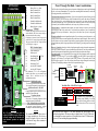
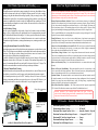
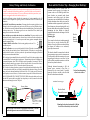
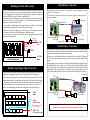
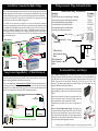

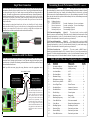
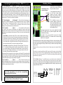
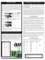
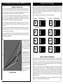

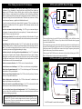
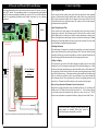

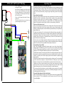
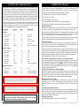

![AWD10SS [obsolete] User Manual](http://vs1.manualzilla.com/store/data/005777265_1-bc3e4afb4b891fb2fe3c32a930faa0e5-150x150.png)

![T9000E [obsolete]](http://vs1.manualzilla.com/store/data/005920932_1-890f13b4deb2f1c3de1d3a852a7c64ca-150x150.png)