1
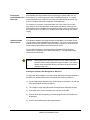
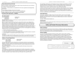
4) Unroll the RG6 coaxial cable that came with the YX500-PCS kit, straighten it,
and then attach it to the Signal Antenna.
Figure 9 - Attach Coaxial Cable to Antenna
Signal Antenna Mounting to an Attic Top or Main Beam
If a cross-beam is not available, the antenna bracket can be mounted to a main
beam. Secure the bracket near the top of the Signal Antenna instead of near the
base.
Figure 10 - Mounting Signal Antenna to a Main Beam
Wireless Extenders
YX500-PCS Installation Guide
9
Running the
Coaxial Cable to the
Base Unit
After installing the Signal Antenna and connecting the coaxial cable, run it to
the location in your home where you plan to install the Base Unit. It is highly
recommended that you refrain from securing your cable, drilling any holes, etc.
until you complete and test the installation of the Base Unit.
For example, if you plan to use put the Base Unit in the living room of a twostory home, first run the cable from the attic down the stairs to the living room.
After the Base Unit is installed and successfully working, find a more direct and
permanent route for the cable (e.g., dropping it through the ceiling of a nearby
closet).
Additional Cable
Requirements
If the distance between the Signal Antenna and the Base Unit exceeds 35 feet,
you will need to purchase additional coaxial cable. You must use RG-6 coaxial
cable and connectors, which are rated for Outdoor Satellite TV use and can be
found at many home improvement and electronic stores.
For the best performance, purchase Wireless Extenders RG-6 extension
cables from our website or your retailer (see page 2). The total cable length
should not exceed 60 feet.
Caution:
Before drilling any holes into a wall to run your cable, make sure
you know where existing electrical wiring is located. If you are not
careful, hitting wiring while drilling could cause an electrical shock
and severe the wire.
Routing the Coaxial Cable Alongside an Attic Pipe
To simply the effort needed to route the coaxial cable from the Signal Antenna to
the Base Unit, Wireless Extenders recommends the following procedure:
1) Locate a pipe which descends from the attic down to a location in or near the
room where signal coverage is desired.
2) Tie a weight to a pull string and lower the weight down alongside the pipe.
3) In the lower room, tie the pull-string onto one end of the cable.
4) Go back to the attic and gently pull up the string until the coaxial cable can
be grasped.
5) Connect the coaxial cable to the Signal Antenna.
10
Wireless Extenders
YX500-PCS Installation Guide
Installing the Base
Unit
For the widest possible signal reception, it recommended that you install the
YX500-PCS Base Unit near the middle of a room or on an interior wall. This is
because the Base Unit uses an omni-directional antenna, which like a lantern
delivers the signal in a circular pattern around the antenna. If you decide to
install the Base Unit on or near an outside wall, we recommend purchasing the
YX024-PCS Directional Base Unit Antenna (see page 2). This antenna will
focus the entire signal in towards the rooms.
The Base Unit can either be directly mounted on a wall or set on a furniture
piece (e.g., a bookshelf, desk, filing cabinet, end table etc.). The Base Unit
performs best when located at least 4 feet above the floor or at about the
height of the cell phone when it is typically in use.
For the best results, avoid placing the Base Unit antenna within 2 feet of other
wires or metal objects.
Placing the Base Unit on a Furniture Piece
The Base Unit is designed so that it easily sits on top of a furniture piece using
the following steps.
1) Attach the coaxial cable, which should already be attached to the Signal
Antenna, to the Base Unit.
Figure 11 - Base Unit Power Cord and Cable Connectors
2) Attach the antenna to the Base Unit and position it so that it is at a 90
degrees angle to the Base Unit.
Wireless Extenders
YX500-PCS Installation Guide
11
3) Set the Base Unit on a furniture piece.
4) Attach the power supply to the Base Unit and plug the power supply into an
outlet. See the Troubleshooting section if a Red LED lights up.
Note:
If you are unable to position the Base Unit so that the Power LED
shines a steady green, you may have to move the Base Unit to
another location in the room, or mount it on a wall. See the
Troubleshooting section for more information.
Wall Mounting the Base Unit
The Base Unit can also be easily mounted on a wall using the included mounting
bracket hardware. The Base Unit must be a minimum of distance of 12" from the
ceiling so their is clearance for the Base Unit antenna extension.
Perform the following steps to mount the Base Unit on a wall:
1) Remove the mounting bracket from the Base Unit
2) Attach the coaxial cable, which should already be attached to the Signal
Antenna, to the Base Unit.
3) Attach the antenna to the Base Unit.
4) Attach the power supply to the Base Unit and plug the power supply into an
outlet. See the Troubleshooting section if a Red LED lights up.
5) Holding the Base Unit, adjust its position on the wall until the LEDs shine a
steady green. The Base Unit can be mounted on the wall with the antenna
pointing to the ceiling or towards the floor.
6) Fasten the mounting bracket to the wall using the self-tapping wall/ceiling
anchors
7) Snap the Base Unit into the mounting bracket.
Note:
Confirm that the
YX500-PCS is
Working Properly
If you are unable to position the Base Unit so that the Power LED
shines a steady green, you may have to move the Base Unit to
another wall in the room.
Perform the following steps to confirm that the YX500-PCS is now working
properly:
1) Unplug the YX500-PCS Base Unit power cord.
12
Wireless Extenders
YX500-PCS Installation Guide
2) Turn on your PCS cell phone and check the signal meter.
3) Turn off your PCS cell phone.
4) Plug-in the YX500-PCS Base Unit power cord.
5) Hold your PCS cell phone about 2 to 3 feet from the Base Unit and
then turn it on. Wait up to 1 minute for the cell phone to register the
signal coming from the Base Unit.
6) If the signal meter shows an improvement, the YX500-PCS is working
properly. You now have Wireless Where You Want It™.
Note:
The Signal LED may flash green indicating that a call is in progress
and the YX500-PCS is boosting your signal. In some cases, it may
only flash at the beginning of the call.
If the Signal LED displays either a solid or flashing red, see the
troubleshooting section.
Improving Your
Coverage Area
Now that everything is connected and the Base Unit is plugged in, you should
walk throughout the room and see that you are able to reliably place calls.
Remember, coverage varies based on outdoor signal level, building
construction, and general installation care). Coverage in adjoining rooms (next
to, above, or below) will be reduced due to the walls or the ceiling/floor.
Should you desire to improve coverage, you may:
1) Move the Base Unit
2) Move the Signal Antenna to a higher location in your attic
3) Purchase a Signal Antenna Upgrade (see Page 2)
4) Purchase a Base Unit Antenna Upgrade (see Page 2).
Important Note on Using Signal Bars to Determine Coverage Area
Cell phone signal bars are approximate and very coarse. The number of bars
can fluctuate widely, depending on the exact location of the phone, hand
positioning, angle of the phone, weather, etc. Most cell phone signal meters
update every 6 to 10 seconds.
THE BEST INDICATOR OF COVERAGE AREA IS YOUR ABILITY TO
RELIABLY PLACE AND RECEIVE CALLS.
Wireless Extenders
YX500-PCS Installation Guide
13
Troubleshooting the YX500-PCS
Base Unit LED
Operation
In most cases, problems with the YX500-PCS can be diagnosed using the
Base Unit’s LEDs.
Mode
Normal / Idle
LED Settings
Power LED = Solid Green
Action
None
Signal LED = Off
Call Detected
Install LED = Off
Power LED = Solid Green
Signal LED = Flashing Green
Oscillation – Reduced Range
Install LED = Off
Power LED = Solid Green
Signal LED = Off
Install LED = Flashing Red (20
seconds)
Oscillation – Base Unit Shutdown
Power LED = Off
Signal LED = Flashing Red
Install LED = Flashing Red
User Caution
Power LED = Solid Green
Signal LED = Flashing Red
Install LED = Off
User Shutdown
Power LED = Off
Signal LED = Solid Red
Network Caution – Reduced
Range
Install LED = Off
Power LED = Solid Green
Signal LED = Flashing Red (20
seconds)
Install LED = Flashing Red (20
seconds)
None
May only Flash at the beginning
of a call.
An oscillation was detected. The
Base Unit has corrected it, but is
operating with reduced range.
To improve range performance,
you must move the antenna(s) to
increase separation. You may
cycle power to re-check for this
condition.
An oscillation was detected but
the Base Unit is unable to correct
it. You must move the
antenna(s) to increase
separation and then unplug the
Power supply.
User’s phone/device is very close
to the Base Unit. Move the
phone/device away from the
Base Unit to avoid User
Shutdown.
User’s phone/device is too close
to the Base Unit. The Base Unit
has temporarily shut down to
prevent network problems.
The Signal Antenna is receiving
an excessive signal from a
nearby cell tower (probably
another service provider) and is
operating with reduced range.
Try making one or more of the
following adjustments:
1. Position the Signal Antenna so
that it is pointing slightly in the
direction of the closest tower.
2. Move the Signal Antenna to
another part of the attic.
14
Wireless Extenders
YX500-PCS Installation Guide
Mode
Network Overdrive – Base Unit
Shutdown
LED Settings
Power LED = Off
Signal LED = Solid Red
Install LED = Solid Red
Action
3. Contact a professional installer
for assistance. You may need to
have a directional antenna
installed.
The Signal antenna is receiving
too much signal from a nearby
cell tower (probably another
service provider. Try one more
of the following to correct the
problem:
1. Slightly adjust the position of
the Signal Antenna so that it is
pointing toward the closest tower.
2. Move the Signal Antenna to
another part of your attic.
3. Contact a professional installer
for assistance. You may need to
have a directional antenna
installed.
YX500-PCS Technical Specifications
Frequency
Networks:
Total Signal Gain:
RF Output Power:
Base Unit Weight:
Base Unit Size:
AC Power Input:
DC Power Output:
FCC ID:
Industry Canada ID:
Patents pending
1850-1990 MHz (PCS only)
CDMA, GSM, TDMA
60dB (adaptive)
< ½ Watt EiRP (with included antenna)
12 oz.
5” x 7” x 2”
100 – 120 VAC 60Hz
5VDC, 1.5A
SO4YX500-PCS
5544A-YX500PCS
Wireless Extenders
YX500-PCS Installation Guide
15