1
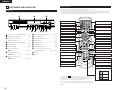
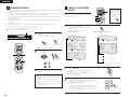
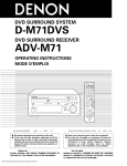
HOME THEATER SYSTEM
Æ a Æ x º v∞|√ ¥≤ Œ
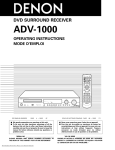
DHT-1000DV
OPERATING INSTRUCTIONS
æ fi ß @ ª°© ˙ Æ —
CH
1
ON
POWER
2
3
VCR
CH
4
OFF
VCR POWER
5
CH
TV POWER
CH
9
TV/VCR
SLEEP
DISPLAY
TV
0
+10
CALL
6
VOL
8
7
CLEAR
RETURN INPUT MODE SURROUND
MENU
FUNCTION
ENTER
MODE
VOLUME
BAND
MUTE
CH
SHIFT
NTSC/PAL STATUS
TU
MEMO
SUB TITLE
DVD SURROUND AMPLIFIER UADV-1000
FUNCTION
/ SELECT
ANGLE
TOP MENU
REPEAT
RANDOM
SDB/TONE
SURR.PARA
MASTER VOLUME
CH.SELECT
PROGRESSIVE SCAN
AUDIO
PROG/DIRECT REPEAT A-B
T.TONE
C 8 1:02:46
SETUP
DIG AUTO
DVD
CDR/MD/TAPE TUNER/TV/VCR
DVD
DIGITAL
ON / STANDBY
REMOCON MODE
REMOTE CONTROL UNIT RC-902
PHONES
AUTO DECODE 5CH STEREO
OPEN / CLOSE
SURROUND
MODE
STATUS
TIMER / SET SDB / TONE
2CH MODE
ADV-1000
USYS-1000
FOR ENGLISH READERS
§§ §Â
PAGE 02 ~ PAGE 47
≤ ƒ 2°A48 ≠ ∂ °„ ≤ ƒ 92 ≠ ∂
ENGLISH
2
2
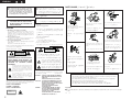
We greatly appreciate your purchase of this unit.
To be sure you take maximum advantage of all
the features this unit has to offer, read these
instructions carefully and use the set properly. Be
sure to keep this manual for future reference
should any questions or problems arise.
2
2
≈ w ™ Ô ¡ ∂ R D H T - 1 0 0 0 D V°C
¨∞ΩT ´ O±z Ø ‡ ® … ® ¸ D H T - 1 0 0 0 D V © “ ¥ £ ® —
™ ∫ ¶ U∫ ÿ • \ Ø ‡°A Ω –•J≤ ” æ \≈ ™•ªª°© ˙ Æ —
°A ®√ æ A∑Ì ¶ a ® œ • Œ • ª æ ˜°C Ω –ߥµ Ω´O¶s•ªª
NOTE ON USE / ® œ • Œ ™ `∑N ®∆ ∂ µ
¶w•˛™`∑N ®∆ ∂ µ
IMPORTANT TO SAFETY
ƒµßi°G
WARNING:
TO PREVENT FIRE OR SHOCK HAZARD,
DO NOT EXPOSE THIS APPLIANCE TO
RAIN OR MOISTURE.
¨∞® æ § Ó § ı ® a © Œπ q¿ª°A Ω –§≈ ±N
• Keep the set free from moisture,
water, and dust.
™`∑N °G
1. § p § fl≥ B≤ zπ q∑Ω≥nΩ u
CAUTION:
1. Handle the power supply cord carefully
Do not damage or deform the power supply cord. If it is
damaged or deformed, it may cause electric shock or
malfunction when used. When removing from wall outlet,
be sure to remove by holding the plug attachment and not
by pulling the cord.
2. Do not open the top cover
In order to prevent electric shock, do not open the top cover.
If problems occur, contact your DENON DEALER.
3. Do not place anything inside
Do not place metal objects or spill liquid inside the personal
audio system.
Electric shock or malfunction may result.
Ω –§≈∑l√ a © Œ ® œπ q∑ Ω ≥n Ω u ≈ ‹ ß Œ°A ¶ pµo • Õ∑l
√ a © Œ≈ ‹ ß Œ°A ∑| ¶ b ® œ • Œ § § æ …≠ Pπ q¿ª©Œ§£•ø
±`π B ß @°C
CAUTION
CAUTION:
TO REDUCE THE RISK OF ELECTRIC SHOCK,
DO NOT REMOVE COVER (OR BACK). NO
USER SERVICEABLE PARTS INSIDE. REFER
SERVICING TO QUALIFIED SERVICE
PERSONNEL.
The lightning flash with arrowhead symbol, within
an equilateral triangle, is intended to alert the user
to the presence of uninsulated “dangerous
voltage” within the product’s enclosure that may
be of sufficient magnitude to constitute a risk of
electric shock to persons.
The exclamation point within an equilateral
triangle is intended to alert the user to the
presence of important operating and maintenance
(servicing) instructions in the literature
accompanying the appliance.
NOTE:
This personal audio system uses the semiconductor laser. To
allow you to enjoy music at a stable operation, it is recommended
to use this in a room of 5°C (41°F) — 35°C (95°F).
CLASS 1 LASER PRODUCT
LUOKAN 1 LASERLAITE
KLASS 1 LASERAPPARAT
,,
CLASS 1
,,
LASER PRODUCT
2
• §≈ ≈˝ ¬ ¯ ™ ´±º§J昧∫°C
•
§≈ ±N • ª æ ˜ © Ò∏m © Û ¿ „ ´◊ ´‹∞
™ © Œ ¶ hπ – ™∫ ¶Ï∏m °C
• ® æ § Ó∞™ ∑≈
∏À © Û æ ˜ ¨ [ Æ … ¿≥ §π ≥\•R§¿¥
±q¿§ W ¥°Æ y © fi • Xπ q∑Ω≥nΩ u Æ …°A Ω –Ω Tª{¥§¶
Ì¥°¿Y¶”´Dπ q∑Ω≥nΩ u°C
2. Ω –§≈ • ¥∂ }昪\
¨∞® æ § Óπ q¿ª°A Ω –§≈ • ¥∂ }昪\°C
µo • Õ∞›√ D °A Ω –ªP§—¿s•N≤ z∞”¡pµ∏°C
3. Ω –§≈ © Ò § J • Ù ¶ Û ™ ´ • Û
Ω –§≈ ¶ b æ ˜ §∫ © Ò § J ™ ˜ ƒ › ™ ´ • Û ® æ § Ó ¬ q § J≤ G ≈ È°C
Please, record and retain the Model name and serial number of
your set shown on the rating label.
Model No. DHT-1000DV Serial No.
RISK OF ELECTRIC
SHOCK DO NOT OPEN
• Avoid high temperatures.
Allow for sufficient heat dispersion
when installed on a rack.
• Do not let foreign objects in the set.
≤ ºˆ°C
• Do not let insecticides, benzene, and
thinner come in contact with the set.
• Unplug the power cord when not
using the set for long periods of
time.
CAUTION
•
RISK OF ELECTRIC
SHOCK DO NOT OPEN
•
¡◊ ß K ¶ b • ª æ ˜ ™ ˛ ™ Ò º Q≈ x± ˛ ¬
Œ æ Ø°M §]§≈ • Œ ® T ™ o°M § —
Æ ≥ § Ù © Œ ® ‰ • ¶∑ª æ Ø © Ÿ ´ ¯
™ ¯ Æ …∂°§ £ ® œ • Œ • ª æ ˜ Æ …∂
™`∑N °G
¨∞® æπ q¿ª°A Ω –§≈ • ¥∂ }昪\°] © Œ ´ ·
ª\ °^ °C • ª æ ˜ § ∫ ≥ ° µ L • i ® —
® œ • Œ ™ à ® œ • Œ ™∫≥°• Û°C Ω –©e¶´
µ•√ ‰ § T ® § ß Œ § § ¶≥ Ωb¿Y∞{π qº–∏ π
™ ∫ πœ ß Œ ™ Ì • ‹ ƒµß i ® œ • Œ ™ à ¶ b≤ £ ´
~ §∫ ¶≥ æ …π q≈ È § Œ∞™ π q¿£°A•i؇∑|
• Handle the power cord carefully.
Hold the plug when unplugging the
cord.
• Ø d∑N π q∑ΩΩu
µ•√ ‰ § T ® § ß Œ § § ¶≥∑Pπ ƒ∏ π™ ∫ πœ
ß Œ ™ Ì • ‹°A ±˝ ƒµ ß i ® œ • Œ ™ Ã∏”≥ ]≥ ∆
¶ b æ fi ß @ ª P ´ Oæi°] ™ A∞»°^ § Ë≠ ±¿≥ ƒ Y
* (For sets with ventilation holes)
*°]≥ ∆¶≥ ≥q≠∑§’™∫ æ ˜ ¥ fl°^
• Do not obstruct the ventilation holes.
• Never disassemble or modify the set
in any way.
• §≈∞Ù ∂ Î æ ˜ ¥ fl ™∫ ≥q≠∑§’°C
• §≈ • ¥∂ } © Œ ¿ H∑N ≠ ◊ ≤z•ªæ˜°C
±q ¥°Æ y º∑•X¥°¿ Y Æ … ¿≥∏”ß϶̥
°¿Y±N ® ‰ º∑• X°C
™ `°G
• ª æ ˜ ® œ • Œ • b æ …≈ È ø Á Æ g°A ¨∞® œ±z•ø±` ™ YΩ ‡
≠ µº÷°Aß⁄≠ à ´ ÿ ƒ≥ ¶b
5¢J°]41¢ K°^ °–
ADVARSEL: USYNLIG LASERSTRÅLING VED ÅBNING,
NÅR SIKKERHEDSAFBRYDERE ER UDE AF
FUNKTION.
UNDGÅ UDSAETTELSE FOR STRÅLING.
VAROITUS! LAITTEEN KÄYTTÄMINEN MUULLA KUIN
TÄSSÄ KÄYTTÖOHJEESSA MAINITULLA
TAVALLA SAATTAA ALTISTAA KÄYTTÄJÄN
TURVALLISUUSLUOKAN 1
YLITTÄVÄLLE NÄKYMÄTTÖMÄLLE
LASERSÄTEILYLLE.
VARNINGOM APPARATEN ANVÄNDS PÅ ANNAT
SÄTT ÄN I DENNA BRUKSANVISNING
SPECIFICERATS, KAN ANVÄNDAREN
UTSÄTTAS FÖR OSYNLIG
LASERSTRÅLNING SOM ÖVERSKRIDER
GRÄNSEN FÖR LASERKLASS 1.
CAUTION
✽ The ventilation should not be impeded by covering the ventilation openings with items,
such as newspapers, table-cloths, curtains, etc.
✽ No naked flame sources, such as lighted candles, should be placed on the apparatus.
✽ Please be care the environmental aspects of battery disposal.
✽ The apparatus shall not be exposed to dripping or splashing for use.
✽ No objects filled with liquids, such as vases, shall be placed on the apparatus.
Copyrights
2 It is prohibited by law to reproduce, broadcast, rent or play discs in public without the consent of the copyright
holder.
™©
≈v
ENGLISH
2 INTRODUCTION
1 BEFORE USING
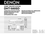
Thank you for choosing the DENON DHT-1000DV Home Theater System. This remarkable component has been engineered to provide
superb surround sound listening with home theater sources such as DVD, as well as providing outstanding high fidelity reproduction
of your favorite music sources.
As this product is provided with an immense array of features, we recommend that before you begin hookup and operation that
you review the contents of this manual before proceeding.
TABLE OF CONTENTS
z
x
c
v
b
n
m
,
.
⁄0
⁄1
⁄2
Before Using .....................................................................3
Cautions on Installation.....................................................3
Cautions on Handling ....................................................3, 4
Features ............................................................................4
Discs .................................................................................5
Cautions on Handling Discs ..............................................5
Connections..................................................................6~9
Part Names and Functions..............................................10
Remote Control Unit .................................................11, 12
Setting up the System..............................................13~17
Play Back ..................................................................17~19
Operation ..................................................................19, 20
⁄3
⁄4
⁄5
⁄6
⁄7
⁄8
⁄9
¤0
¤1
¤2
¤3
¤4
Dolby / DTS Surround ...............................................21, 22
Surround Playback ....................................................22~26
DSP Surround Simulation .........................................26~28
Listening to the Radio...............................................28, 29
On-Screen Display ..........................................................30
• Moving the set
To prevent short circuits or damaged wires in the
connection cords, always unplug the power cord and
disconnect the connection cords between all other audio
components when moving the set.
• Store this instructions in a safe place.
After reading, store this instructions along with the warranty
in a safe place.
• Note that the illustrations in this instructions may differ
from the actual set for explanation purposes.
• Before turning the power switch on
Check once again that all connections are proper and that
there are not problems with the connection cords. Always
set the power switch to the standby position before
connecting and disconnecting connection cords.
Using the On-Screen Display....................................30~37
Using the Timer ........................................................37~39
Changing the Default Settings (DVD) .......................40~45
Last Function Memory....................................................45
Initialization of the Microprocessor .................................45
Troubleshooting...............................................................46
Specifications ..................................................................47
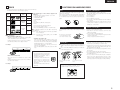
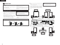
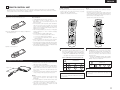
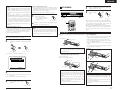
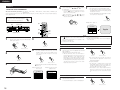
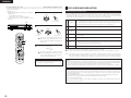
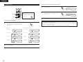
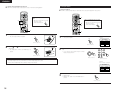
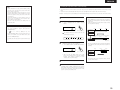
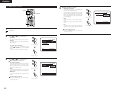
2 ACCESSORIES
2 ADV-1000 (Main unit)
Check that the following parts are included in addition to the main unit:
q Operating instructions…..1
r R6P/AA batteries..…….....2
y FM indoor antenna….......1
Pay attention to the following before using this unit:
w Service station list............….............................1
t AM loop antenna................................…...........1
u Video cord…..................................................... 1
e Remote control unit
(RC-902)............…...........1
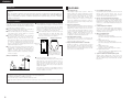
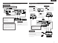
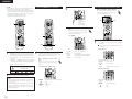
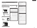
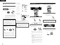
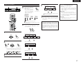
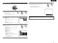
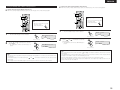
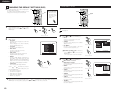
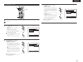
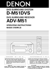
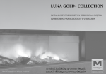
2 CAUTIONS ON INSTALLATION
Noise or disturbance of the picture may be generated if this
unit or any other electronic equipment using microprocessors
is used near a tuner or TV.
If this happens, take the following steps:
• Install this unit as far as possible from the tuner or TV.
• Set the antenna wires from the tuner or TV away from this
unit’s power cord and input/output connection cords.
• Noise or disturbance tends to occur particularly when using
indoor antennas or 300 Ω/ohms feeder wires. We
recommend using outdoor antennas and 75 Ω/ohms
coaxial cables.
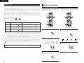
10 cm or more
C 8 1:02:46
DIG AUTO
DVD
DIGITAL
10 cm or more
For heat dispersal, leave at least 10 cm of space between
the top, back and sides of this unit and the wall or
other components.
Wall
e
r
ON
ON
POWER
1
1
OFF
OFF
VCR
CLEAR POWER
TV
CALL POWER
DISPLAY
MENU
0
0
INPUT
4
4
8
8
3
3
6
6
VOL
SLEEP
u
2
2
5
5
TV/VCR
MODE
y
CH
CH
CH
7
7
+10CH
RETURN
t
VCR
9
9
TV
SURROU
ND
FUNCT
ENTER
ION
MODE
BAND
CH
SUB
TITLE
PROG/DIR
ECT
CDR/MD/T
APE
MENU
RANDOM
SDB/TON
E
TUNER/T
V/VCR
REMOCO
N MODE
MEMO
TOP
REPEAT
T.TONE
SETUP
NTSC/P
MUTE
MUTE
AL SHIFT
STATUS
ANGLE
A-B
CT
VOLUM
E
TU
AUDIO
REPEAT
CH.SELE
SURR.P
ARA
DVD
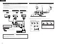
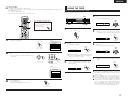
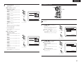
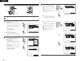
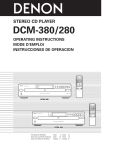
3 CAUTIONS ON HANDLING
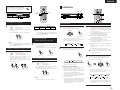
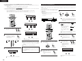
2 USYS-1000 (speaker unit pack)
Before using, check that the package contains the main speaker units (4 units of the USC-A1000 (2 pairs), 1 USC-C1000
and 1 USW-1000) and the accessories shown below.
q Speaker cord A………..…..…..…..…..…..….….….…2
(Used to connect the USC-A1000)
Length: Approx. 10 meters
e Foot................…….....…..…..…..…..…..….….….…24
q
w
w Speaker cord B............….........................................4
(Used to connect the USC-A1000, USC-C1000 and
USW-1000)
Length: Approx. 3 meters
e
• Switching the input function when input jacks are not
connected
A clicking noise may be produced if the input function is
switched when nothing is connected to the input jacks. If
this happens, either turn down the MASTER VOLUME
control or connect components to the input jacks.
• Whenever the power switch is in the STANDBY state,
the apparatus is still connected on AC line voltage.
Please be sure to unplug the cord when you leave home
for, say, a vacation.
• Muting of PRE OUT jacks, HEADPHONE jack and
SPEAKER terminals
The PRE OUT jacks, HEADPHONE jacks and SPEAKER
terminals include a muting circuit. Because of this, the
output signals are greatly reduced for several seconds after
the power switch is turned on or input function, surround
mode or any other-set-up is changed. If the volume is turned
up during this time, the output will be very high after the
muting circuit stops functioning. Always wait until the
muting circuit turns off before adjusting the volume.
3
ENGLISH
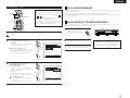
Speaker units
When installing the speakers, take careful considerations for safety when selecting the place and method of
installation.
When using stands or brackets, follow their instructions and check for safety before using and installing. To
install on ceilings or walls, to ensure safety have a specialist do the installation work. Note that DENON will
accept no responsibility for injuries or accidents resulting from the speakers falling, etc., due to improper
installation or mounting.
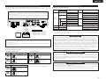
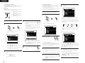
4 FEATURES
1.
Cautions on installation
The quality of the sound produced from the speakers depends
2 When installing the USC-A1000 on a table, etc., attach four
on the size of the room, the type of room (Japanese style or
of the included foot (cork approx. 2 mm thick) to the four
western style) and how the speakers are mounted. Consider
corners of the bottom of the speaker (see the diagram
the following when installing the speakers:
below). If the bass seems unnaturally emphasized when the
2 Note that installing a speaker system on the same table or
speakers are installed directly on the floor, place the
shelf as a record player may result in howling.
speakers on concrete blocks or other hard surfaces.
2 If there is a wall or glass pane, etc., directly in front or in back
When installing the speakers on stands, use the mount
of the speaker system, use thick curtains, etc., to prevent
screws included with the stands and tighten them
resonance or reflection of the sound.
securely so that there is no looseness in the mount
2 The USYS-1000 speaker systems are of the anti-magnetic
holes (nuts) on the bottoms of the speakers.
type allowing them to be used near televisions, etc.
[Rear of USC-A1000]
[Bottom of USC-A1000]
Depending on the type of TV, however, the colors on the
TV’s picture may be blotched. If so, turn the TV’s power off,
then wait 15 to 30 minutes before turning the power back
on. The TV’s self-degaussing circuit will reduce the
influence on the picture. If color blotching persists, move the Wall mount
hook
speaker further away from the TV.
2 The USC-C1000 is designed so that the front surface can be
faced upwards or downwards according to the place of
installation. We recommend facing it downwards when
installed in a position above the ears, upwards when
Speaker stand/speaker
installed on the floor. Attach the included foot (cork approx.
bracket mount screw holes
2 mm thick) to adjust.
Position for attaching foot
(cork approx. 2 mm thick)
Facing
USC-C1000
[Example of installation]
downwards
2 Using the USC-A1000 suspended on a wall
The USC-A1000 can be used suspended on a wall, using the
wall mount hole on the rear of the speaker. To do so,
suspend the speaker by catching a screw, etc., stuck in the
wall in the hole in the wall mount hook (see the above
diagram). Be sure the wall is strong enough to support the
Facing
upwards
weight of the speaker.
Note that Denon will accept no responsibility for injuries or
accidents resulting from the speakers falling, etc., due to
USC-C1000
improper installation or mounting.
NOTES:
• For safety, do not place objects on top of the speakers or lean objects against them.
• The speakers may fall if force is applied to their sides.
This could cause injury or serious accident. Be sufficiently careful.
• Fasten the speaker cords in place to prevent the risk of catching the cords on your hands or feet and causing the speakers to
fall.
4
2.
Dolby Digital decoder
Dolby Digital, a digital discrete system in which the
different channels are completely independent, recreates
“three-dimensional” sound fields (sounds with a sense of
distance, movement and position) with no crosstalk
between channels for greater reality. In addition, the 5
channels (excluding the 0.1 channel for low frequency
effects) have a playback range extending to 20 kHz, the
same as the range of CDs, thus resulting in clearer, more
richly expressive sound.
Dolby Pro Logic II decoder
Dolby Pro Logic II is a new format for playing multichannel
audio signals that offers improvements over conventional
Dolby Pro Logic. It can be used to decode not only sources
recorded in Dolby Surround but also regular stereo sources
into five channels (front left/right, center and surround
left/right). In addition, various parameters can be set
according to the type of source and the contents, so you
can adjust the sound field with greater precision.
3.
DTS (Digital Theater Systems)
DTS provides up to 5.1 channels of wide-range, high
fidelity surround sound, from sources such as laser disc,
DVD and specially-encoded music discs.
4.
High performance DSP simulates 7 sound fields
Playback is possible in 7 surround modes: 5-channel
Stereo, Mono Movie, Rock Arena, Jazz Club, Video Game,
Matrix and Virtual. You can enjoy a variety of sound effects
for different movie scenes and program sources even with
stereo sources not in Dolby Surround.
5.
Personal Memory Plus function
Personal Memory Plus is an advanced version of Personal
Memory. With Personal Memory Plus, the set
automatically memorizes the surround mode and input
mode for each of the separate input sources.
6.
Remote control unit with pre-memory function
This unit comes with a remote control unit equipped with a
pre-memory function. The remote control command codes for
DENON remote controllable components as well as for video
decks, TVs, etc., of other major manufacturers are prestored in
the memory.
7.
6-channel digital power amplifier
The ADV-1000 is equipped with a 55W + 55W (6 Ω/ohms,
1 kHz, T.H.D. 10%) 6-channel digital power amplifier,
allowing 5.1-channel surround playback when used in
combination with the super woofer.
8.
Many convenient functions
(1) Multiple audio function
Selection of up to 8 audio languages.
(The number of languages offered differs from DVD to
DVD.)
(2) Multiple subtitle function
Selection of up to 32 subtitle languages.
(The number of languages offered differs from DVD to
DVD.)
(3) Multiple angle function
The angle of view can be changed.
(For DVDs on which multiple angles are recorded.)
(4) Playback disable function
This function can be used to disable playback of DVDs
you do not want children to watch.
9.
Stylish 5.1-channel surround AV speaker system
Satellite speaker equipped with a super tweeter unit
capable of reproducing a wide frequency range of up to 80
kHz, plus a passive super woofer producing clear, firm
bass sound.
ENGLISH
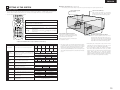
5 DISCS
6 CAUTIONS ON HANDLING DISCS
• The types of discs listed on the table below can be used on the ADV-1000.
The marks are indicated on the disc labels or jackets.
Usable
discs
Mark (logo)
Recorded
signals
Disc size
DVD video
DVD audio
(NOTE 1)
Digital audio +
digital video
(MPEG2)
12 cm
Digital audio +
digital video
(MPEG1)
12 cm
Video CD
8 cm
8 cm
12 cm
CD
CD-R
CD-RW
(NOTE 2)
Digital audio
MP3
8 cm
Recordable
ReWritable
2 Disc terminology
• Titles and chapters (DVD-videos)
DVD-videos are divided into several large sections called
“titles” and smaller sections called “chapters”.
Numbers are allotted to these sections. These numbers
are called “title numbers” and “chapter numbers”.
For example:
Title 1
Title 2
Discs
2 The following types of discs cannot be played on the
ADV-1000:
• DVDs with region numbers other than “3” or “ALL”
• DVD audio discs (NOTE 1)
• DVD-R/ –RW / +RW
• DVD-ROM/RAMs
• CVD
• SVCD
• CD-ROMs (Only MP3 file can be played)
• VSDs
• CDVs (Only the audio part can be played.)
• CD-Gs (Only the audio is output.)
• Photo CDs (NEVER play such discs on the ADV-1000)
If you attempt to play photo CDs, the data on the disc may
be damaged.
NOTE 1: Video part which based on DVD-video specification
only can be played.
NOTE 2: According to recording quality, some CD-R/RW
cannot be played.
• Playback control (video CDs)
Video CDs including the words “playback control” on the
disc or jacket are equipped with a function for displaying
menus on the TV screen for selecting the desired position,
displaying information, etc., in dialog fashion.
In this manual, playing video CDs using such menus is
referred to “menu playback”.
Video CDs with playback control can be used on the ADV1000.
Chapter 1 Chapter 2 Chapter 3 Chapter 1 Chapter 2
• Tracks (video and music CDs)
Video and music CDs are divided into sections called
“tracks”.
Numbers are allotted to these sections. These numbers
are called “track numbers”.
For example:
Track 1
Track 2
Track 3
Track 4
Track 5
NOTE:
• This DVD video player is designed and
manufactured to respond to the Region
Management Information that is
recorded on a DVD disc.
If the Region number described on the
DVD disc does not correspond to the
Region number of this DVD video
player, this DVD video player cannot
play this disc.
The Region number for this DVD video
player is 3.
Cautions on Handling Discs
Only the discs including the marks shown on page 5 can be
played on the ADV-1000.
Note, however, that discs with special shapes (heart-shaped
discs, hexagonal discs, etc.) cannot be played on the ADV-1000.
Do not attempt to play such discs, as they may damage the
player.
Holding Discs
• Do not get fingerprints, grease or dirt on discs.
• Be especially careful not to scratch discs when removing
them from their cases.
• Do not bend discs.
• Do not heat discs.
• Do not enlarge the center hole.
• Do not write on the labeled (printed) side with a ball-point
pen or a pencil.
• Water droplets may form on the surface if the disc is moved
suddenly from a cold place to a warm one. Do not use a
hairdryer, etc., to dry the disc.
Cautions on Storing Discs
Avoid touching the surface of discs when loading and unloading
them.
Be careful not to get fingerprints
on the signal surface (the side
which shines in rainbow colors).
• Always eject discs after playing them.
• Keep discs in their cases to protect them from dust,
scratches and warping.
• Do not put discs in the following places:
1. Places exposed to direct sunlight for long periods of time
2. Humid or dusty places
3. Places exposed to heat from heaters, etc.
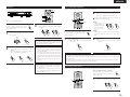
Cautions on Loading Discs
Cleaning Discs
2 Fingerprints or dirt on the disc may lower sound and picture
quality or cause breaks in playback. Wipe off fingerprints or
dirt.
2 Use a commercially available disc cleaning set or a soft cloth
to wipe off fingerprints or dirt.
3
Wipe gently from the middle
outwards.
• Only load one disc at a time. Loading one disc on top of
another may result in damage or scratch the discs.
• Load 8 cm discs securely in the disc guide, without using an
adapter. If the disc is not properly loaded, it may slip out of
the guide and block the disc tray.
• Be careful not to let your fingers get caught when the disc
tray is closing.
• Do not place anything but discs in the disc tray.
• Do not load cracked or warped discs or discs that have been
fixed with adhesive, etc.
• Do not use discs on which the adhesive part of cellophane
tape or glue used to attach the label is exposed, or discs
with traces of tape or labels that have been peeled off. Such
discs may get stuck inside the player, resulting in damage.
Do not wipe with a circular
motion.
NOTE:
• Do not use record spray or antistatic. Also do not use
volatile chemicals such as benzene or thinner.
Record
spray
Thinner
Benzene
5
ENGLISH
7 CONNECTIONS
• Do not plug in the AC cord until all connections have been
completed.
• Be sure to connect the left and right channels properly (left
with left, right with right).
• Insert the plugs securely. Incomplete connections will
result in the generation of noise.
• Note that binding pin plug cords together with AC cords or
placing them near a power transformer will result in
generating hum or other noise.
• Noise or humming may be generated if a connected audio
equipment is used independently without turning the
power of this unit on. If this happens, turn on the power of
the this unit.
2 Connect using the speaker cords included with the USYS1000.
Be sure to turn off the power of the ADV-1000 when
connecting the speaker units to it.
• Use the included speaker cords to connect the input
terminals on the backs of the speaker units (see diagram at
right) to the speaker output terminals on the ADV-1000.
Note that if the polarities are not properly interconnected,
the phase may be off and the sound may be unnatural (no
bass).
NOTE:
DO NOT touch the speaker terminals when the power is on.
Doing so could result in electric shock.
Super woofer
(USW-1000)
(1) Speaker system connections
• Use speaker cords with twisted wire cores and a diameter
of 0.6 to 1.5 mm. Never use cords thicker than 1.5 mm or
single-wire cords, as they may damage the speaker
terminals.
• Be sure to interconnect the polarities of the terminals on the
speakers and main unit (≈ to ≈, √ to √).
• When making connections, be careful that none of the core
wires of the speaker cords stick out and touch neighboring
terminals, other speaker cords or the rear panel.
• Speakers with an impedance of 6 to 16 Ω/ohms can be
connected for use as center and surround speakers.
(L)
(R)
NOTE:
NEVER touch the speaker terminals when the power is
on.
Doing so could result in electric shocks.
• The protector circuit may be activated if the set is played for
long periods of time at high volumes when speakers with an
impedance lower than the specified impedance are
connected.
Connection the speaker terminals
1. Push the lever.
Surround speaker
(USC-A1000)
2. Insert the cord.
Speaker cord B (length:
approx. 3 meters)
(included)
Speaker cord A
(length: approx.
10 meters)
(included)
Speaker cord A (length:
approx. 10 meters)
(included)
3. Return the lever.
LOOP ANT.
VIDEO
S VIDEO
MON.OUT
IN
TV/DBS
IN
V.AUX
IN
OUT
MON.OUT
VCR
IN
TV/DBS
IN
V.AUX
IN
OUT
VCR
FM COAX. 75
Y
CB
CR
L
AM
PRE OUT
R
COMPONENT VIDEO OUT
R
L
FRONT
CENTER
IMPEDANCE SUB
WOOFER
6 16
SPEAKER SYSTEMS
SUB WOOFER
IN
OUT
CDR/
TAPE
IN
TV/DBS
IN
V.AUX
IN
OUT
IN
TV/DBS
VCR
AUDIO
IN
V.AUX
OUT
DIGITAL(OPTICAL)
Speaker cord B (length: approx. 3 meters)
(included)
Speaker cord B (length: approx. 3 meters)
(included)
Speaker cord B
(length: approx.
3 meters)
(included)
(L)
Front speaker
(USC-A1000)
6
R
L
SURROUND
Center speaker
(USC-C1000)
(R)
Front speaker
(USC-A1000)
ENGLISH
(2) Connecting the audio components
(3) Connecting video components
• To connect the video signal, connect using a 75 Ω/ohms video signal cable cord. Using an improper cable can result in a drop in
video quality.
• When making connections, also refer to the operating instructions of the other components.
• When making connections, also refer to the operating instructions of the other components.
Connecting the DIGITAL (optical) jacks
Use these for connections to audio equipment with digital (optical) output.
Connecting a CS tuner
V.AUX
Connecting a TV/DBS tuner
NOTE:
• Use optical cables for optical connections, removing the cap before connecting.
TV/DBS
• Connect the CS tuner’s video output jack (VIDEO OUTPUT)
to the VIDEO (yellow) V.AUX IN jack using a 75 Ω/ohms
video coaxial pin plug cord.
• Connect the CS tuner’s audio output jacks (AUDIO
OUTPUT) to the AUDIO V.AUX IN jacks using pin plug
cords.
• For devices with optical digital outputs, connect the digital
output terminal to the ADV-1000’s DIGITAL V.AUX. IN
terminal using an optical transmission cable.
• Connect the TV’s or DBS tuner’s video output jack
AC CORD
Monitor TV
(VIDEO OUTPUT) to the VIDEO (yellow) TV/DBS IN
jack using a 75 Ω/ohms video coaxial pin plug cord.
AC 230 V, 50 Hz
VIDEO
IN
• Connect the TV’s or DBS tuner’s audio output jacks
MON.OUT
IN
TV/DBS
IN
V.AUX
IN
OUT
MON.OUT
VCR
IN
TV/DBS
IN
V.AUX
IN
(AUDIO OUTPUT) to the AUDIO TV/DBS IN jacks
LOOP ANT.
VIDEO
S VIDEO
OUT
VCR
FM COAX. 75
Y
CB
CR
L
AM
PRE OUT
R
COMPONENT VIDEO OUT
R
L
FRONT
CENTER
IMPEDANCE SUB
WOOFER
6 16
SPEAKER SYSTEMS
SUB WOOFER
R
L
SURROUND
IN
OUT
CDR/
TAPE
IN
TV/DBS
IN
V.AUX
IN
OUT
IN
TV/DBS
VCR
AUDIO
IN
V.AUX
OUT
DIGITAL(OPTICAL)
using pin plug cords.
• For devices with optical digital outputs, connect the
digital output terminal to the ADV-1000’s DIGITAL
TV/DBS IN terminal using an optical transmission
cable.
R
L
B
• Connect the TV’s video input
jack (VIDEO INPUT) to the
VIDEO MONITOR OUT jack
using a 75 Ω/ohms video
coaxial pin plug cord.
TV or DBS tuner
R
L
CS tuner
MONITOR OUT
B
Subwoofer jack
VIDEO
OUT
Connect the internal amplifier’s subwoofer to
the subwoofer terminal.
OPTICAL
OUT
• To conduct digital recording onto a digital recorder (CD recorder,
MD recorder, etc.) while playing Dolby Digital, 96 kHz PCM
sources on this DVD player.
• Set the “AUDIO SETUP” default setting as shown below. (See
page 43.)
• “DIGITAL OUT” → “PCM”
“LPCM SELECT” → “ON”
Playing DVDs with incorrect settings may result noise that could
damage your ears or the speakers.
R
L
R
CD recorder, MD recorder or
Tape deck
L
AUDIO
OUT
R
L
R
OPTICAL
AUDIO
OUT
R
L
VIDEO
OUT
OUT
L
R
L
B
R
L
OUTPUT
R
L
INPUT
IN
OPTICAL
LOOP ANT.
VIDEO
S VIDEO
Connecting a recorder
MON.OUT
IN
TV/DBS
IN
V.AUX
IN
OUT
MON.OUT
VCR
IN
TV/DBS
IN
V.AUX
IN
OUT
VCR
FM COAX. 75
NOTES:
• Track numbers may not be added automatically when
making digital recordings of CDs being played on the ADV1000 onto a connected recorder.
• When making digital recordings on a CD recorder, set the
CD recorder’s recording setting to manual and add track
numbers (track marks) manually as you record.
• When making digital recordings on an MD recorder, use
the editing function after the recording is completed to
divide the tracks.
Connections for recording:
Connect the tape deck’s recording input jacks (LINE IN or REC) to
this unit’s tape recording (CDR/TAPE OUT) jacks using pin plug
cords.
Connections for playback:
Connect the tape deck’s playback output jacks (LINE OUT or PB)
to this unit’s tape playback (CDR/TAPE IN) jacks using pin plug
cords.
Y
CB
CR
L
AM
PRE OUT
R
COMPONENT VIDEO OUT
SUB WOOFER
IN
OUT
CDR/
TAPE
Note on connecting the digital input jacks
• Only audio signals are input to the digital
input jacks.
• Use optical cables for optical connections,
removing the cap before connecting.
R
L
IN
TV/DBS
IN
V.AUX
IN
OUT
L
OUT
IN
V.AUX
IN
TV/DBS
VCR
AUDIO
DIGITAL(OPTICAL)
R
L
R
L
R
Connecting a video decks
Video input/output connections:
R
• Connect the video deck’s video output jack (VIDEO OUT) to the
VIDEO
VCR IN jack, and the video deck’s video input jack (VIDEO IN) to the
VIDEO
(yellow) VCR OUT jack using 75 Ω/ohms video coaxial pin plug cords.
Connecting the audio output jacks
• Connect the video deck’s audio output jacks (AUDIO OUT) to the
jacks, and the video deck’s audio input jacks (AUDIO IN) to the
L
R
R
L
OUT
R
VCR IN
L
IN
OUT
IN
AUDIO
AUDIO
AUDIO
L
(yellow)
VIDEO
Video deck
VCR OUT
jacks using pin plug cords.
7
ENGLISH
(4) Connecting a video component equipped with S-Video jacks
(5) Connecting the antenna terminals
• When making connections, also refer to the operating instructions of the other components.
• A note on the S input jacks
The input selectors for the S inputs and pin jack inputs work in conjunction with each other.
• Precaution when using S-jacks
This unit’s S-jacks (input and output) and video pin jacks (input and output) have independent circuit structures, so that video
signals input from the S-jacks are only output from the S-jack outputs and video signals input from the pin jacks are only output
from the pin jack outputs.
When connecting this unit with equipment that is equipped with S-jacks, keep the above point in mind and make connections
according to the equipment’s instruction manuals.
Connecting a monitor TV
Connecting a TV/DBS tuner
MONITOR OUT
• Connect the TV’s S video input (S-VIDEO
INPUT) to the S-VIDEO MONITOR OUT
jack using a S jack connection cord.
AM LOOP
ANTENNA
(Supplied)
FM INDOOR
ANTENNA
(Supplied)
FM ANTENNA
75 Ω/ohms
COAXIAL
CABLE
Connecting a CS tuner
• Connect the TV’s or DBS tuner’s S
video output jack (S-VIDEO
OUTPUT) to the S-VIDEO TV/DBS
IN jack using an S jack connection
cord.
• Connect the CS tuner’s S video output
jack (S-VIDEO OUTPUT) to the
S-VIDEO V.AUX. IN jack using an S
jack connection cord.
LOOP ANT.
VIDEO
OUT
MON.OUT
CR
IN
TV/DBS
IN
V.AUX
IN
OUT
VCR
FM COAX. 75
L
AM
R
Monitor TV
CS tuner
TV or DBS tuner
S-VIDEO
IN
DIRECTION OF
BROADCASTING
STATION
IN
OUT
CDR/
TAPE
IN
TV/DBS
IN
V.AUX
IN
OUT
VCR
AUDIO
IN
TV/DBS
IN
V.AUX
OUT
DIGITAL(OPTICAL)
FM ANTENNA
ADAPTER
(Option)
B
B
AM OUTDOOR
ANTENNA
S-VIDEO
OUT
S-VIDEO
OUT
GROUND
• An PAL-type FM antenna cable plug can be connected directly.
• If the FM antenna cable’s plug is not of the PAL-type, connect using the PAL-type antenna adapter (option).
AM loop antenna assembly
Connection of AM antennas
Connect to the AM
antenna terminals.
1
LOOP ANT.
VIDEO
S VIDEO
MON.OUT
IN
TV/DBS
IN
V.AUX
IN
OUT
MON.OUT
VCR
IN
TV/DBS
IN
V.AUX
IN
OUT
VCR
4
FM COAX. 75
L
Connect the components’ audio inputs
and outputs as described on page 7.
AM
PRE OUT
IN
OUT
CDR/
TAPE
IN
TV/DBS
IN
V.AUX
AUDIO
IN
OUT
VCR
IN
TV/DBS
IN
V.AUX
OUT
DIGITAL(OPTICAL)
Mount
Connecting the video decks
b. With the
antenna
attached to a
wall.
• Connect the video deck’s S output jack (S-OUT) to the
S-VIDEO
to the
VCR IN jack and the video deck’s S input jack (S-IN)
S-VIDEO
VCR OUT jack using S jack connection cords.
Video deck
Installation hole
Mount on wall, etc.
S-VIDEO
IN
S-VIDEO
OUT
NOTES:
• Set the “TV TYPE” in “VIDEO SETUP” in “DVD SETUP”
• Connect this unit video outputs to the TV either directly.
to comply with your TV’s video format. When the TV is
Do not connect it via a VCR (video cassette recorder).
PAL formated set to PAL.
Some discs contain copy prohibit signals. If such discs are
played via a VCR, the copy prohibit system may cause
disturbance in the picture.
8
3. Return the lever.
3
Remove the vinyl tie
Bend in the reverse
and take out the
direction.
connection line.
a. With the
antenna on top
any stable
surface.
R
SUB WOOFER
2
1. Push the lever. 2. Insert the conductor.
Notes:
• Do not connect two FM antennas simultaneously.
• Even if an external AM antenna is used, do not disconnect
the AM loop antenna.
• Make sure AM loop antenna lead terminals do not touch
metal parts of the panel.
ENGLISH
(6) Connecting to a TV or Monitor Equipped with Component Input Connectors
(7) Sound output from this unit digital audio output connectors
• When making connections, also refer to the operating instructions of the other components.
• The video signals input to the VIDEO input (yellow) and S-Video input jacks are not output to the color difference (component)
video jacks.
2 When a disc is played on the ADV-1000
Audio recording format
MON.OUT
IN
TV/DBS
IN
V.AUX
IN
OUT
MON.OUT
VCR
IN
TV/DBS
IN
V.AUX
IN
CB
DVD video
DVD audio
(video part only)
OUT
L
Digital out : Normal
DTS bitstream
Digital out : PCM conversion
DTS bitstream
LPCM conversion mode : OFF
48 kHz/16 ~24 bit PCM
DTS
VCR
CR
2 channels PCM data (48 kHz/16 bit)
43
FM COAX. 75
Y
Digital audio data output
Dolby Digital bitstream
Digital out : Normal
Digital out : PCM conversion
LOOP ANT.
VIDEO
S VIDEO
Refer to
page
Dolby Digital
AM
PRE OUT
Linear PCM
Color component output connectors (CR, CB and Y)
The red (CR), blue (CB) and brightness (Y) signals are output independently, achieving more faithful
reproduction of the colors.
• The color component input connectors may be marked differently on some TVs or monitors (PR, PB
and Y/R-Y, B-Y and Y/CR, CB and Y, etc.). For details, refer to the TV’s operating instructions.
Settings
48 kHz
LPCM conversion mode : ON
96 kHz
LPCM conversion mode : ON
48 kHz/16 bit PCM
43
48 kHz/16 bit PCM
CP : ON
LPCM conversion mode : OFF
48 kHz/16 bit PCM (when copy-protected)
CP : OFF
LPCM conversion mode : OFF
96 kHz PCM (when not copy-protected)
R
COMPONENT VIDEO OUT
R
L
FRONT
CENTER
IMPEDANCE SUB
WOOFER
6 16
SPEAKER SYSTEMS
SUB WOOFER
R
L
SURROUND
IN
OUT
CDR/
TAPE
IN
TV/DBS
IN
V.AUX
IN
OUT
IN
TV/DBS
VCR
AUDIO
IN
V.AUX
OUT
DIGITAL(OPTICAL)
Video CD
MPEG 1
44.1 kHz/16 bit PCM
Music CD
Linear PCM
44.1 kHz/16 bit PCM
MP3 CD
Connecting a monitor TV
• Connect the TV’s color difference
(component)
video
input
jacks
(COMPONENT VIDEO INPUT) to the
COMPONENT VIDEO OUT jack using
75 Ω/ohms coaxial video pin-plug cords.
Monitor TV
Y
CB
CR
NOTES:
• Use the three commercially available video cords to connect the ADV-1000’s color component output connectors
to the TV or monitor.
• Set the “TV TYPE” in “VIDEO SETUP” in “DVD SETUP” to comply with your TV’s video format. When the TV is
PAL formated set to PAL.
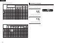
2 Selecting the type of disc for the type of connected TV
Both DVD discs and video CDs have the material recorded in the PAL and NTSC systems. Refer to the table below to select the
correct disc type for the type of connected TV.
Disc
TV Monitor
• Connecting to the PAL TV
Disc
Played in the PAL system.
PAL
TV Monitor
Played in the PAL system.
PAL
Played in the NTSC system.
NTSC
• Linear PCM audio is the signal recording format used for music CDs.
While the signals are recorded at 44.1 kHz/16 bit for music CDs, for DVDs they are recorded at 48 kHz/16 bit to 96 kHz/24 bit,
providing higher sound quality than music CDs.
Protector circuit
COMPONENT VIDEO IN
• Connecting to the Multi-system TV
32 ~ 48 kHz/16 bit PCM
MP 3
NTSC
• This unit is equipped with a high-speed protection circuit. The purpose of this circuit is to protect the
speakers under circumstances such as when the output of the power amplifier is inadvertently shortcircuited and a large current flows, when the temperature surrounding the unit becomes unusually high,
or when the unit is used at high output over a long period which results in an extreme temperature rise.
When the protection circuit is activated, the speaker output is cut off and the power supply indicator LED
flashes. Should this occur, please follow these steps: be sure to switch off the power of this unit, check
whether there are any faults with the wiring of the speaker cables or input cables, and wait for the unit to
cool down if it is very hot. Improve the ventilation condition around the unit and switch the power back on.
If the protection circuit is activated again even though there are no problems with the wiring or the
ventilation around the unit, switch off the power and contact a DENON service center.
Note on speaker impedance
• The protector circuit may be activated if the set is played for long periods of time at high volumes when
speakers with an impedance lower than the specified impedance (for example speakers with an
impedance of lower than 4 Ω/ohms) are connected. If the protector circuit is activated, the speaker output
is cut off. Turn off the set’s power, wait for the set to cool down, improve the ventilation around the set,
then turn the power back on.
No clear images are shown
on the screen.
Cautions on connecting
• Connecting to the NTSC TV
Disc
PAL
TV Monitor
No clear images are shown
on the screen.
NOTE:
When a disc which does not comply with Video CD standard is
played, the bottom part of the picture may disappear.
• With this unit’s speaker outputs, signals with the reverse phase of the “+” side output terminal’s signals
are also output from the “-” side output terminal.
Do not connect to a device for switching between multiple speakers (a speaker selector or audio channel
selector) or connect in ways other than described in this manual. Doing so will result in damage.
Played in the NTSC system.
NTSC
9
ENGLISH
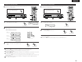
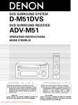
8 PART NAMES AND FUNCTIONS
Remote control unit
• For details on the functions of these parts, refer to the pages given in parentheses ( ).
• Some of the buttons on the remote control unit have two functions.
The functions are switched using the remote control mode selector buttons (CDR/MD/TAPE, TUNER/TV/VCR and DVD). After
one of these buttons is pressed, the function will not switch until another remote control mode selector button is pressed.
The remote control unit’s mode switches as described below when the buttons are pressed.
Front Panel
• For details on the functions of these parts, refer to the pages given in parentheses ( ).
!9
!8
!7
DVD SURROUND RECEIVER ADV-1000
FUNCTION
/ SELECT
CH
MASTER VOLUME
1
ON
POWER ON/OFF button ..........................(17)
C 8 1:02:46
POWER
ON / STANDBY
PHONES
AUTO DECODE 5CH STEREO
SURROUND
MODE
STATUS
TIMER/SET SDB/TONE
VCR POWER
OPEN / CLOSE
BAND
- TUNING +
TV POWER
q we
q
w
e
r
t
Power operation switch (ON/STANDBY) .........(17)
Headphones jack (PHONES) ..........................(20)
Remote control signal sensor
(REMOTE SENSOR) .......................................(11)
r
t
y
u
OPEN/CLOSE button (5 OPEN/CLOSE) .........(17)
Play button (1)...............................................(18)
Pause button (3) ......................................(18, 19)
Stop/Tuner band button
y
u
!0
!1
!2
!3
!4
!5
!6
!7
(2/BAND) ...........................................(18, 28, 29)
i
Skip/Tuner tuning – button
(8/TUNING –) ................................(19, 28, 29)
o
Skip/Tuner tuning + button
(9/TUNING +)...............................(19, 28, 29)
i
o !0 !2 !4
!1 !3 !5
!6
AUTO DECODE/2CH MODE button ........(22, 23)
5CH STEREO button ......................................(19)
SURROUND MODE button............................(19)
STATUS button ...............................................(20)
DISPLAY button .......................................(30)
DISPLAY
RETURN button .................................(18, 19)
MENU
9
CH
TV/VCR
SLEEP
TV
0
FUNCTION
INPUT MODE selector
button.......................................................(19)
FUNCTION selector button......................(19)
ENTER
ENTER button ..........................................(13)
Cursor buttons .........................................(13)
Main volume control buttons...................(20)
*
System buttons .......................................(12)
MODE
MUTE button ...........................................(20)
VOLUME
BAND
SUBTITLE button ....................................(35)
STATUS button ........................................(20)
MUTE
MASTER VOLUME control ............................(20)
Input function switching/select dial
AUDIO selector button ...........................(35)
CH
SHIFT
NTSC/PAL STATUS
TU
MEMO
SUB TITLE
AUDIO
ANGLE
TOP MENU
REPEAT
RANDOM
SDB/TONE
SURR.PARA
(FUNCTION/SELECT) ...................(19~21, 37, 38)
!8
!9
SURROUND mode selector
button.......................................................(19)
RETURN INPUT MODE SURROUND
MENU button...........................................(37)
TIMER/SET button ...................................(37, 38)
SDB/TONE button ..........................................(20)
SLEEP button...........................................(39)
VOL
+10
CALL
System buttons .......................................(12)
6
8
7
CLEAR
CALL button.............................................(33)
5
CH
2CH MODE
*
3
VCR
4
OFF
CLEAR button ..........................................(33)
2
CH
Display
Program/direct button
(PROG/DIRECT) .......................................(33)
PROG/DIRECT REPEAT A-B
CH.SELECT
Disc tray .........................................................(17)
A-B repeat button
(REPEAT A-B) ...........................................(32)
SETUP
T.TONE
CDR/MD/TAPE TUNER/TV/VCR
NTSC/PAL button .......................................(8)
TOP MENU button .................................(36)
ANGLE button .........................................(36)
DVD
RANDOM button .....................................(33)
Channel select button
(CH. SELECT)...........................................(22)
REMOCON MODE
REMOTE CONTROL UNIT RC-902
REPEAT button ........................................(32)
Test tone button (T.TONE) .......................(22)
Surround parameter button
(SURR.PARA).....................................(22~26)
SETUP button ..........................................(13)
SDB/TONE selector button......................(20)
Remote control mode
selector buttons
Remote control mode
CDR/MD/TAPE
Audio modes
TUNER/TV/VCR
AV modes
• Buttons indicated
are DVD operation buttons. These can be used when the
DVD mode is selected with the remote control mode selector buttons.
• The system buttons (*) are buttons whose functions differ according to which mode
is selected with the remote control mode selector buttons.
• Other buttons are surround amplifier operation buttons that always operate in the
same way, regardless of which mode is set with the remote control mode selector
buttons.
10
DVD
DVD modes
ENGLISH
9 REMOTE CONTROL UNIT
(3) Preset memory
• The included remote control unit (RC-902) can be used to operate not only this unit but other remote control compatible
DENON components as well. In addition, the memory contains the control signals for other remote control units, so it can be
used to operate non-Denon remote control compatible products.
[1] Audio Component
• The signals of your other Denon products can be stored in the
included remote control unit’s preset memory to operate
either the CDR, MD or TAPE function.
Operation is not possible for some models.
(1) Inserting the batteries
q Remove the remote control unit’s rear cover.
w Set three R6P/AA batteries in the battery compartment in
the indicated direction.
e Put the rear cover back on.
Notes on Batteries
• Use R6P/AA batteries in the remote control unit.
• The batteries should be replaced with new ones
approximately once a year, though this depends on the
frequency of usage.
• Even if less than a year has passed, replace the batteries
with new ones if the set does not operate even when the
remote control unit is operated nearby the set. (The included
battery is only for verifying operation. Replace it with a new
battery as soon as possible.)
• When inserting the batteries, be sure to do so in the proper
direction, following the “≈” and “√” marks in the battery
compartment.
• To prevent damage or leakage of battery fluid:
• Do not use a new battery together with an old one.
• Do not use two different types of batteries.
• Do not short-circuit, disassemble, heat or dispose of
batteries in flames.
• Remove the batteries from the remote control unit when
you do not plan to use it for an extended period of time.
• If the battery fluid should leak, carefully wipe the fluid off the
inside of the battery compartment and insert new batteries.
• When replacing the batteries, have the new batteries ready
and insert them as quickly as possible.
1
CH
1
ON
POWER
2
3
5
6
4
VCR POWER
CH
TV POWER
9
CH
TV/VCR
SLEEP
DISPLAY
1
RETURN INPUT MODE SURROUND
MENU
DIG
AUTO
DIGITAL
30°
ON
ON
POWER
OFF
OFF
VCR
CLEAR POWER
TV
CALL POWER
DISPLAY
MENU
+10CH
RETURN
INPUT
1
1
4
4
0
0
TV/VCR
CH
2
2
3
3
5
5
8
8
6
6
VOL
SLEEP
SURROUN
FUNCT
ION
CH
CH
7
7
MODE
ENTER
9
9
TV
VCR
30°
2:4
6
CH
SUB
TITLE
PROG/DIRE
T
VOLUM
E
NTSC/PA
L
MUTE
SHIFT
MUTE
STATUS
MENU
RANDOM
SURR.PA
RA
VCR
MODE
RC-902
DVD
NOTES:
• It may be difficult to operate the remote control unit if the
remote sensor is exposed to direct sunlight or strong
artificial light.
• Do not press buttons on the main unit and remote control
unit simultaneously. Doing so may result in malfunction.
• Neon signs or other devices emitting pulse-type noise
nearby may result in malfunction, so keep the set as far
away from such devices as possible.
DISPLAY
1
TV
RETURN INPUT MODE SURROUND
FUNCTION
VOLUME
BAND
MUTE
MUTE
AUDIO
PROG/DIRECT REPEAT A-B
CH.SELECT
SETUP
T.TONE
ANGLE
SUB TITLE
TOP MENU
AUDIO
PROG/DIRECT REPEAT A-B
REPEAT
RANDOM
SDB/TONE
SURR.PARA
CH.SELECT
DVD
SETUP
CDR/MD/TAPE TUNER/TV/VCR
MEMO
TU
MEMO
TU
SUB TITLE
SHIFT
NTSC/PAL STATUS
CH
SHIFT
NTSC/PAL STATUS
CH
T.TONE
ANGLE
TOP MENU
REPEAT
RANDOM
SDB/TONE
SURR.PARA
CDR/MD/TAPE TUNER/TV/VCR
DVD
REMOCON MODE
REMOCON MODE
1
1
While pressing the CDR/MD/TAPE remote control mode
selector button, input the 3-digit number (“000”, “111”
and “222”) corresponding to the device you want to
preset (CDR, MD or TAPE), referring to the table below.
• Release the CDR/MD/TAPE button after inputting
three digits. This completes the presetting operation.
Input the 3-digit number while pressing
CDR/MD/TAPE.
CDR
0
0
0
MD
1
1
1
TAPE
2
2
2
This is set to CDR by factory default.
D
MEMO
TOP
REPEAT
E
TUNER/TV/
REMOCON
UNIT
ANGLE
A-B
SDB/TON
PE
CONTRO
L
REPEAT
T.TONE
CDR/MD/TA
E
TU
AUDIO
CT
CH.SELEC
SETUP
REMOT
SLEEP
0
MODE
MODE
BAND
TV/VCR
VOLUME
BAND
CDR/MD/TAPE
C 8
1:0
CH
ENTER
MODE
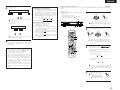
(2) Using the remote control unit
DVD
9
MENU
FUNCTION
Table 1: Combinations of Personal System Codes
Approx. 7m
8
+10
CALL
ENTER
1
• Point the remote control unit at the remote sensor on the
main unit as shown on the diagram.
• The remote control unit can be used from a straight distance
of approximately 7 meters from the main unit, but this
distance will be shorter if there are obstacles in the way or
if the remote control unit is not pointed directly at the
remote sensor.
• The remote control unit can be operated at a horizontal angle
of up to 30 degrees with respect to the remote sensor.
VCR
6
VOL
7
TV POWER
0
3
5
CH
CLEAR
TV
2
4
VCR POWER
8
+10
CALL
1
CH
OFF
VOL
7
CLEAR
CH
ON
POWER
VCR
CH
OFF
[2] TV
• Other makes of components can be operated by setting the
preset memory for your make of TV.
This remote control unit can be used to operate components
of other manufacturers without using the learning function by
registering the manufacturer of the components as shown on
the List of Preset Codes (attached sheet).
Operation is not possible for some models.
NOTE:
• Only one device (CDR, MD or TAPE) can be stored in the
preset memory.
1
Press the CALL button while pressing the
TUNER/TV/VCR remote control mode selector button,
then input the three-digit number corresponding to the
code of the manufacturer of the TV whose signals you
want to store, referring to the included list of remote
control unit codes.
• Release the TUNER/TV/VCR button after inputting
three digits. This completes the presetting operation.
Example: To preset to “Hitachi 074”
TUNER/TV/VCR
HITACHI
“074”
Press the buttons below while pressing
TUNER/TV/VCR.
TV POWER
CALL
0
7
4
This is set to “Hitachi 074” by factory default.
NOTE:
• Preset codes set upon shipment from the factory and
when reset.
11
VCR POWER
ENGLISH
TV POWER
[3] VCR
• Other makes of components can be operated by setting the
preset memory for your make of video component.
This remote control unit can be used to operate components
of other manufacturers without using the learning function by
registering the manufacturer of the components as shown on
the List of Preset Codes (attached sheet).
Operation is not possible for some models.
(4) Operating DENON audio components
1
VOLUME
BAND
CH
SHIFT
NTSC/PAL STATUS
TU
MEMO
3
5
6
CH
CH
9
SLEEP
DISPLAY
RETURN INPUT MODE SURROUND
DISPLAY
6
CH
VOL
8
9
TV/VCR
SLEEP
7
CLEAR
TV POWER
CALL
3
5
VCR
4
VCR POWER
TV
0
+10
CALL
2
CH
OFF
1
VOL
8
TV/VCR
7
CLEAR
TV POWER
1
ON
POWER
VCR
4
VCR POWER
1
2
CH
CH
TV
:
0
+10
AUDIO
:
:
:
:
:
6
7
2
1
CH
1
ON
POWER
ANGLE
CH
1
ON
TOP MENU
POWER
Rewind
Fast-forward
Stop
Forward Play
Reverse Play
FUNCTION
ENTER
ENTER
MODE
VOLUME
VOLUME
BAND
TV POWER
SHIFT
NTSC/PAL STATUS
TU
MEMO
SUB TITLE
AUDIO
PROG/DIRECT REPEAT A-B
ANGLE
CH
TV/VCR
SLEEP
1-a
TV
0
RETURN INPUT MODE SURROUND
MENU
FUNCTION
TUNER/TV/VCR
MODE
VOLUME
BAND
MUTE
CH
SHIFT
NTSC/PAL STATUS
MEMO
TU
SUB TITLE
c. For TUNER
MUTE
CH
SHIFT
NTSC/PAL STATUS
REPEAT
RANDOM
SDB/TONE
SURR.PARA
CH.SELECT
DVD
SETUP
AUDIO
PROG/DIRECT REPEAT A-B
ANGLE
ANGLE
AUDIO
CH.SELECT
T.TONE
TOP MENU
REPEAT
RANDOM
SDB/TONE
SURR.PARA
PROG/DIRECT REPEAT A-B
MEMO
TU
SUB TITLE
TOP MENU
9
+10
CALL
DISPLAY
BAND
1
MUTE
CH
8
7
CLEAR
6
VOL
ENTER
Before operating the remote control
unit!
Be sure to press the proper remote control
mode selector button to set the remote
control unit to the AV mode.
TV POWER
MODE
5
CH
RETURN INPUT MODE SURROUND
MENU
FUNCTION
3
VCR
4
VCR POWER
1-b
2
CH
OFF
VCR POWER
MENU
TUNER/TV/VCR
MUTE
CH
OFF
Before operating the remote control unit!
Be sure to press the proper remote control
mode selector button to set the remote
control unit to the AV mode.
MODE
SUB TITLE
POWER
(5) Operating a video component stored in the preset memory
b. For tape deck (TAPE)
TOP MENU
MODE
REPEAT
RANDOM
SDB/TONE
SURR.PARA
VOLUME
CH.SELECT
SETUP
T.TONE
CDR/MD/TAPE TUNER/TV/VCR
T.TONE
BAND
DVD
CDR/MD/TAPE TUNER/TV/VCR
MUTE
CH
REMOCON MODE
SHIFT
NTSC/PAL STATUS
REMOCON MODE
1-a,b
1
1-c,z
MEMO
TU
SUB TITLE
AUDIO
PROG/DIRECT REPEAT A-B
1
Press the CLEAR button while pressing the
TUNER/TV/VCR remote control mode selector button,
then input the 3-digit number corresponding to the code
of the manufacturer of the VCR you want to store in the
memory, referring to the included table of remote
control codes.
• Release the TUNER/TV/VCR button after inputting
three digits. This completes the presetting operation.
Example: To preset to Hitachi “072”
TUNER/TV/VCR
HITACHI
“072”
Press the buttons below while pressing
TUNER/TV/VCR.
1
DENON remote-controllable audio components can be
controlled using this unit’s remote control unit.
Note that some components, however, cannot be
operated with this remote control unit.
POWER
VCR POWER
Before operating the remote control
unit!
Be sure to set the audio device mode
using the remote control mode selector
buttons.
TV POWER
a. For CDR recorder or MD recorder
TOP MENU
REPEAT
RANDOM
: Switch preset channel range
: Preset channel up/down
Operate the TV or VCR.
• For details, refer to the component’s operating
instructions.
Some models cannot be operated with this remote
control unit.
a. For monitor TV
CH
ON
POWER
:
:
:
:
OFF
Tuning up/down
Switch between AM and FM bands
Switch between AUTO and MONO
Preset memory
VCR POWER
CLEAR
TV POWER
CALL
DISPLAY
TV POWER
CHANNEL
(+, –)
VOLUME
(•,ª)
TV/VCR
7
3
VCR
5
CH
7
CH
+10
6
VOL
8
9
TV/VCR
SLEEP
TV
0
RETURN INPUT MODE SURROUND
FUNCTION
: Power on/off
: Switch channel
: Volume up/down
: Switch between TV and VCR
VOLUME
ON
1
2
3
BAND
POWER
OFF
MUTE
CH
This is set to Hitachi “072” by factory default.
SHIFT
NTSC/PAL STATUS
VCR POWER
MEMO
TV POWER
CLEAR
TU
SUB TITLE
AUDIO
ANGLE
CALL
TOP MENU
DISPLAY
12
2
CH
2
NOTES:
• Some models and years of manufacture of components
of the manufacturers listed on the List of Preset Codes
cannot be used.
• The unit is equipped with several types of remote control
codes which depend on the manufacturer. If there is no
operation, please change the preset code (a 3-digit
number) and try again.
4
MENU
MODE
0
1
CH
b. For video deck (VCR)
TV POWER
CALL
CDR/MD/TAPE
SHIFT
CHANNEL
(+, –)
TUNING (+, –)
BAND
MODE
MEMORY
ANGLE
1
PROG/DIRECT REPEAT A-B
6,7
2
1
8,9
3
:
:
:
:
:
REPEAT
VCR
CH
4
5
CH
7
CH
+10
6
VOL
8
9
TV/VCR
SLEEP
TV
0
RETURN INPUT MODE SURROUND
RANDOM
Manual search (reverse and forward)
Stop
Play
Auto search
Pause
VCR POWER
CHANNEL
(+, –)
6,7
1
2
: Power on/off
: Switch channel
: Forward and Reverse
: Play
: Stop
ENGLISH
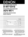
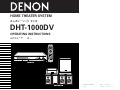
2 Speaker system layout (basic system layout)
• The following shows a basic example of layout for a system consisting of six speaker systems and a TV.
10 SETTING UP THE SYSTEM
(1) System setup items
POWER
• Once all connections with other AV components have been completed as described in “CONNECTIONS” (see pages 6 to 9),
make the various settings described below on the monitor screen using the ADV-1000’s on-screen display function.
• Use the following buttons to set up the system:
VCR POWER
Center speaker system
(USC-C1000)
TV POWER
DISPLAY
Super woofer (USW-1000)
Place so that the distance to the listening
position is the same as the distance between
the front speakers and the listening position.
RETURN INPUT MODE SURROUND
MENU
ENTER
ENTER button
Press this to switch the display.
Also use this button to complete the setting.
MODE
VOLUME
BAND
CURSOR buttons
MUTE
SHIFT
NTSC/PAL STATUS
CH
MEMO
TU
SUB TITLE
AUDIO
PROG/DIRECT REPEAT A-B
CH.SELECT
SETUP
T.TONE
ANGLE
REPEAT
RANDOM
SDB/TONE
SURR.PARA
CDR/MD/TAPE TUNER/TV/VCR
and
:
and
:
TOP MENU
Use these to move the cursors (
on the screen.
Use these to move the cursors (
on the screen.
and
) to the left and right
and
) to the up and down
Front speaker systems (USC-A1000)
Place the front speaker systems at the sides
of the TV or screen, with their front panels as
flush with the screen as possible.
Place the speaker systems symmetrically on
the sides of the screen.
DVD
REMOCON MODE
SETUP button
Press this to display the system setup menu.
Surround speaker systems (USC-A1000)
Place the surround speaker systems 60 cm to 1
meter behind the listening position and 60 cm to 1
meter above the height of the ears (symmetrically
on the sides). Point the surround speakers straight
ahead rather than towards the listening position.
Setup items and default values (set upon shipment from the factory)
Setup
DVD SETUP
ADVANCED SETUP
SYSTEM SETUP
QUICK SETUP
Set the size of the room and the listening position.
Input the combination of speakers in your system and
their corresponding sizes (SMALL for regular speakers,
SPEAKER
LARGE for full-size, full-range) to automatically set the
CONFIGURATION composition of the signals output from the speakers and
the frequency response.
DELAY TIME
This parameter is for optimizing the timing with which the
audio signals are produced from the speakers and
subwoofer according to the listening position.
Default settings
ROOM
SPACE
SEATING
POSITION
FRONT
SP.
CENTER
SP.
SURROUND
SUBSP.
WOOFER
MEDIUM
4.2m x 4.2m
(14 ft x 14 ft)
BACK
SMALL
2.7m (9 ft)
SMALL
2.4m (8 ft)
SMALL
YES
2.1m (7 ft) 2.7m (9 ft)
FRONT SP.
CENTER SP.
SMALL
SMALL
SURROUND SP. SUB WOOFER
SMALL
YES
SW FREQ. = 120 Hz / SW MODE = NONE
FRONT & SW
CENTER
SURROUND
2.7m (9 ft)
2.4m (8 ft)
2.1m (7 ft)
CHANNEL
LEVEL
At the listening position, listen to the test tones output FRONT L
from the different speakers and set so that the playback
0 dB
level from the different speakers is equal.
DVD AUTO
POWER OFF
The power automatically switches to standby if no
operation is performed for 30 minutes while in the stop
mode with the function set to DVD.
DISC SETUP
Set the audio language, subtitle language and disc menu
language for when playing discs.
OSD SETUP
Set the wallpaper for the setup and operation screens.
VIDEO SETUP
Set the screen size and video system for the TV being
used.
TV ASPECT
4 : 3 PS
MULTI
AUDIO SETUP
Set the digital audio signal format and the linear PCM
sampling frequency and bit conversion.
DIGITAL OUT
LPCM SELECT
NORMAL
OFF
Make the playback restriction setting for DVDs with
restricted viewing and set the password required for
changing the setting.
RATING LEVEL
PASS WORD CHANGE
RATINGS
NO LIMIT
0000 (Default)
Make the closed caption setting for DVDs. (A
OTHER SETUP commercially available decoder is required to display the
closed captions.)
CENTER
FRONT R
0 dB
0 dB
• Place the front and center speakers with their fronts as flush
as possible with the TV or screen. Place the center speaker
between the left and right front speakers and no further
away from the listening position than the front speakers.
• There are no particular limitations to where the super woofer
can be placed, but ideally it’s front should be flush with the
screen.
• When placing the center speaker on top of the TV or when
suspending the surround speakers from the walls, secure
them in place so they do not fall during earthquakes.
• If it is not possible to arrange the speakers as described
above due to space restrictions in the room, etc., and the
distance between the different speakers and the listening
position differs greatly, refer to “Delay time (distance
settings)” on page 16 to adjust the sound produced from the
different speakers according to their distance to the listening
position so as to achieve the optimal surround effect.
SURROUND L SURROUND R SUB WOOFER
0 dB
0 dB
0 dB
NO (power does not turn off automatically)
DIALOG
SUBTITLE
DISC MENU
ENGLISH
ENGLISH
ENGLISH
WALL PAPER: BLUE
TV TYPE
CLOSED CAPTION : OFF
13
ENGLISH
(2) Before setting up the system
(3) Quick system settings (to switch between the 2- and 5.1-channel modes)
• This section describes surround-related setup operations.
For DVD-related setup operations, see page 40.
• The setup operations cannot be performed while discs are playing. Set the stop mode first.
1
2
2
• The ADV-1000 is preset with Quick System settings for a 5.1-channel surround system using five small speakers.
See “(4) System setting changes” (pages 15 to 17 when using speaker systems other than the ones described below or if you
wish to change the settings.
Refer to “CONNECTIONS” (pages 6 to 9) and check
that all connections are correct.
Turn on the power.
Press the POWER switch (button).
1
2
ON / STANDBY
Light
(green)
ON
POWER
2
1
POWER
2
VCR
4
5
CH
TV POWER
CH
8
9
TV/VCR
SLEEP
DISPLAY
Main unit
RETURN INPUT MODE SURROUND
MENU
FUNCTION
4
ENTER
5
MUTE
SHIFT
NTSC/PAL STATUS
Press the SETUP button.
SELECT :
DEC I S ION: ENTER BUTTON
AUDIO
ANGLE
3
TOP MENU
SETUP MENU
PROG/DIRECT REPEAT A-B
CH.SELECT
SETUP
3
SETUP
MEMO
TU
SUB TITLE
3
T.TONE
REPEAT
RANDOM
SDB/TONE
SURR.PARA
CDR/MD/TAPE TUNER/TV/VCR
B
QUICK SETUP
Remote control
unit
REMOCON MODE
Use the
and
cursor
buttons to select “Seating
Position”, then use the
and
cursor buttons to
set the size of the position.
Remote control unit
<ADVANCED SETUP>
SYSTEM SETUP
DVD SETUP
DVD
• The set position is displayed in yellow.
>EXIT SETUP
QUICK SETUP MENU
SELECT :
4
Use the
and
cursor buttons
on the remote control unit to select
the setting menu.
• There are three types of setup
menus.
SELECT :
Remote control unit
Press the ENTER button to display
the setting screen of the respective
menu.
ENTER
Remote control unit
14
B
EXIT
ROOM SPACE : (4.2X4.2m)
SMALL
MED. LARGE
SEATING POSITION
CENTER BACK
<SETUP VALUES>
FRONT
SMALL 2.4m
CENTER
SMALL 1.8m
SURROUND
SMALL 2.4m
SUBWOOFER YES
2.4m
DEC I S ION: ENTER BUTTON
B QUICK SETUP: Select “ROOM SPACE” and
“SEATING POSITION”.
B SYSTEM SETUP: Detailed settings of the AV
system function
B DVD SETUP: Detailed settings of the DVD function
5
Remote control
unit
To change the settings
At the setup screen, select “SYSTEM SETUP” from
“<ADVANCED SETUP>”.
About the quick system settings
VOLUME
CH
SETUP
B
EXIT
ROOM SPACE : (4.2X4.2m)
SMALL
MED. LARGE
SEATING POSITION
CENTER BACK
<SETUP VALUES>
FRONT
SMALL 2.7m
CENTER
SMALL 2.4m
SURROUND
SMALL 2.1m
SUBWOOFER YES
2.7m
When pressed, the power turns on and the display lights. The
sound is muted for several seconds, after which the unit
operates normally. When pressed again, the power turns off,
the standby mode is set and the display turns off.
Whenever the ON/STANDBY button is in the STANDBY state,
the apparatus is still connected on AC line voltage. Please be
sure to unplug the cord when you leave home for, say, a
vacation.
MODE
BAND
Press the SETUP button to quit the
setup mode.
Remote control unit
QUICK SETUP MENU
TV
0
+10
CALL
6
VOL
7
CLEAR
Remote control unit
3
CH
OFF
VCR POWER
5
You can also quit the setup mode
by using the
cursor button at
the setup screen to display “Quit
setup” in yellow then pressing
the ENTER button.
Use the
and
cursor
buttons to select “Room Space”,
then use the
and
cursor
buttons to set the size of the room.
• The set size is displayed in
yellow.
CH
ON
At the setup screen, select “QUICK SETUP”, then press
the ENTER button. (See page 13.)
4
DEC I S ION: ENTER BUTTON
Press the ENTER button to enter the
setting.
• The setup screen reappears.
ENTER
Remote control unit
ROOM SPACE:
Set the size of the room in which you are using the
product.
SMALL:
3.0 m x 3.0 m (10 ft x 10 ft)
MED.:
4.2 m x 4.2 m (14 ft x 14 ft)
LARGE:
6.0 m x 6.0 m (20 ft x 20 ft)
SEATING POSITION:
Set whether the seating position is near the center of the
room or towards the back.
CENTER
BACK
Settings:
When “ROOM SPACE” or “SEATING POSITION” is
selected, the distance from the listening position to the
different speakers is displayed automatically.
If the relative distance is very different from the actual
distance (for example if a shorter distance is displayed
for the front speakers than for the center speaker but
actually the opposite is true), set the distance as
described in “ADVANCED SETUP” (page 15).
ENGLISH
(4) System setting changes
• The quick system settings and factory default settings are changed at the system setting change menu.
• The settings are stored in the memory until they are next changed, even when the power is turned off.
[1] Setting the type of speakers
• The composition of the signals output from the different channels and the frequency response are adjusted automatically
according to the combination of speakers actually being used.
1
2
At the SETUP MENU, select “SYSTEM SETUP” and
press the ENTER button.
At the SYSTEM SETUP MENU screen, use the
and
cursor buttons to select the speaker system you
are using.
“SPEAKER CONFIGURATION” and press the ENTER
button.
SYSTEM SETUP MENU
B
DEC I S ION: ENTER BUTTON
ENTER
\
Remote control unit
3
Remote control unit
Set whether or not speakers are connected and, if so,
their size parameters.
CENTER SPEAKER
FRONT SPEAKERS
SUB WOOFER
Remote control unit
SURROUND
SPEAKERS
• The item to be set is displayed in yellow, and the
values of the other items are displayed in green.
SPEAKER CONFIGURATION
B
FRONT SP. :
LARGE SMALL
CENTER S P . :
LARGE SMALL NONE
SURROUND S P . :
LARGE SMALL NONE
SUBWOOFER : Y E S NO
SW F R E Q . : 1 2 0 H z
SW MODE : L F E LFE + MAIN
SELECT :
Enter the setting.
• The SYSTEM SETUP MENU
reappears.
ENTER
Remote control unit
NOTE:
• Select “LARGE” or “SMALL” not according to the actual
size of the speaker but according to the speaker’s
capacity for playing low frequency (approximately 100 Hz
and below) signals. If you do not know, try comparing the
sound at both settings (setting the volume to a level low
enough so as not to damage the speakers) to determine
the proper setting.
SPEAKER CONFIGURATION
DELAY TIME
CHANNEL LEVEL
DVD AUTO POWER O F F
> SETUP MENU
SELECT :
4
Subwoofer frequency (SW FREQ.)
• For the subwoofer frequency at the speaker setting
screen, set the bass crossover frequency for playback
from the subwoofer.
• Select “80 Hz”, “120 Hz”, “150 Hz” or “180 Hz” (-6 dB
for each). Bass sound below these frequencies is played
from the subwoofer.
(This is set to “120 Hz” by factory default.)
Parameters
LARGE……. Select this when using speakers that can fully
reproduce low sounds of below 100 Hz.
SMALL…… Select this when using speakers that do not
provide sufficient volume for playing low
frequencies of 100 Hz and less. When this
setting is made, frequencies below the
frequency set at the subwoofer frequency
setting are assigned to the subwoofer.
NONE…….. Select this when no speakers are installed.
YES/NO…... Select “Yes” when a subwoofer is installed,
“No” when a subwoofer is not installed.
If the subwoofer has sufficient low frequency playback
capacity, good sound can be achieved even when
“Small” is set for the front, center and surround
speakers.
For the majority of speaker system configurations, using
the SMALL setting for all five main speakers and
Subwoofer On with a connected subwoofer will yield the
best results.
Assignment of low frequencies
• In the Dolby Digital, Dolby Pro Logic II, DTS, and virtual
surround modes, the low frequency signals for channels
whose speaker settings are set to “Small” are assigned
to the subwoofer. The low frequencies of channels set
to “Large” are played from those channels.
(If set to “120 Hz”, channels set to “Small” play sounds
of 120 Hz and greater, while bass frequencies of under
120 Hz are played from the subwoofer.)
• In surround modes other than the ones listed above, low
frequencies below the frequency set at the subwoofer
frequency setting are played from the subwoofer
regardless of whether the speakers are set to “Large” or
“Small”.
• Set the subwoofer frequency according to the low
frequency playback abilities of your speakers and
subwoofer.
Subwoofer mode (SW MODE)
• The subwoofer mode setting is only valid when
“LARGE” is set for the front speakers and “YES” is set
for the subwoofer in the “SPEAKER CONFIGURATION”
settings.
• When the “LFE+MAIN” playback mode is selected, the
low frequency signal range of channels set to “LARGE”
are produced simultaneously from those channels and
the subwoofer channel.
In this playback mode, the low frequency range expand
more uniformly through the room, but depending on the
size and shape of the room, interference may result in a
decrease of the actual volume of the low frequency
range.
• Selection of the “LFE ” play mode will play the low
frequency signal range of the channel selected with
“LARGE” from that channel only. Therefore, the low
frequency signal range that are played from the
subwoofer channel are only the low frequency signal
range of LFE (only during Dolby Digital or DTS signal
playback) and the channel specified as “SMALL” in the
setup menu.
• Select the play mode that provides bass reproduction
with body.
• When the subwoofer is set to “YES”, bass sound is
output from the subwoofer regardless of the subwoofer
mode setting in surround modes other than Dolby/DTS.
FINISH: ENTER BUTTON
15
ENGLISH
[2] Setting the speaker distance
• Input the distances from the listening position to the
speakers and set the surround delay time.
• The default settings below are set upon shipment from the
factory.
Preparations:
Measure the distances from the listening position to the
speakers (L1 to L3 on the diagram at the right).
[3] Setting the channel level
• Use this setting to adjust so that the playback level between
the different channels is equal.
• From the listening position, listen to the test tones produced
from the speakers to adjust the level.
• The level can also be adjusted directly from the remote
control unit. (For details, see page 23.)
L1: Distance from center speaker to
listening position
L2: Distance from front speakers to
listening position
L3: Distance from surround speaker
to listening position
To perform these operations from places other than the
system setting change menu, see page 15.
FL
Center
FR
L1
L2
Listening
position
1
2
\
To perform these operations from places other than the
system setting change menu, see page 15.
4
At the SYSTEM SETUP MENU select “DELAY TIME”.
Select the speaker to be set using the
and
cursor buttons, then setting the distance between the
speakers and the listening position using the
and
cursor buttons.
Remote control unit
AUTO MANUAL
YES
+10dB
0dB
0dB
0dB
0dB
0dB
FINISH: ENTER BUTTON
SELECT :
Remote control unit
• Test tones are automatically emitted from the different
speakers.
• The test tones are emitted from the different speakers in
the following order, at 4-second intervals the first time and
second time around, 2-second intervals the third time
around and on:
• Switch to the CHANNEL LEVEL screen.
FRONT L
• Set the distance between the center speaker and
listening position.
The distance changes in units of 0.1 meters (1 foot)
each time the button is pressed. Select the value
closest to the measured distance.
\
Remote control unit
DELAY TIME
DELAY TIME
• Use the
3
SELECT :
cursor button to proceed to the next
5
SETUP
MENU
TEST TONE MODE
LEVEL CLEAR
TEST TONE START
FRONT L
CENTER
FRONT R
SURROUND R
SURROUND L
SUBWOOFER
When “YES” is selected for “DEFAULT”, the delay
times for the various speakers are set to the default
values.
FRONT & SW / 2.7 m
CENTER / 2.4 m
SURROUND / 2.1 m
B NO: The current settings are used.
Select “TEST TONE MODE”.
• Select the mode.
B
AUTO MANUAL
YES
+10dB
0dB
0dB
0dB
0dB
0dB
Remote control unit
FINISH: ENTER BUTTON
SELECT :
Select “AUTO” or “MANUAL”.
• AUTO: Adjust the level while listening to the test tones
produced automatically from the different speakers.
• MANUAL: Select the speaker from which you want to
produce the test tone to adjust the level.
• Use the CURSOR
and
to select the speaker for
which you want to output test tones, then use the CURSOR
and
to adjust so that the volume of the test tones
from the various speakers is the same.
4
Remote control unit
B YES:
w When the “MANUAL” mode is selected
FINISH: ENTER BUTTON
ENTER
step if you do not wish to change this.
SURROUND R
• Use the CURSOR buttons to adjust all the speakers to the same
volume.
• The volume can be adjusted between –12 dB and +12 dB in units
of 1 dB.
0dB
0dB
0dB
0dB
0dB
0dB
FINISH: ENTER BUTTON
The difference of the distances set for the different
speakers must be no greater than 3.0 m (10 ft.).
If an inapplicable distance is set, “CAUTION:
INVALID DISTANCE” is displayed. Change the
speaker position and reset.
Enter the setting.
• The SYSTEM
reappears.
SURROUND L
CHANNEL LEVEL
cursor buttons to select the
distance unit, “METERS” or “FEET”.
Press the
SELECT :
FRONT R
CENTER
B
AUTO MANUAL
B
FINISH: ENTER BUTTON
and
B
SET THE DISTANCE TO EACH SPEAKERS
UNIT
METERS F E E T
DEFAULT
FRONT&SW
2.7m
CENTER
2.4m
SURROUND
2.1m
SET THE DISTANCE TO EACH SPEAKERS
UNIT
METERS F E E T
DEFAULT
FRONT&SW
2.7 m
CENTER
2.4 m
SURROUND
2.1 m
SELECT :
SUBWOOFER
CHANNEL LEVEL
TEST TONE MODE
LEVEL CLEAR
TEST TONE START
FRONT L
CENTER
FRONT R
SURROUND R
SURROUND L
SUBWOOFER
Remote control unit
• Switch to the DELAY TIME screen.
If “YES” is selected at “LEVEL CLEAR”, the level
settings for all the speakers are set to 0 dB.
B “YES” : The levels of the different speakers are all set to
0dB.
B “NO” : The speakers stay at their currently set levels.
7
After the above settings are completed, press the
ENTER button.
• The “SYSTEM SETUP MENU” screen reappears.
✽ To cancel the setting after adjusting
Display the channel level adjustment screen, then use the
5
Adjusting the channel levels in the “test tone” mode
• Set the “TEST TONE START” mode using the
and
cursor buttons, then select “YES” with the
cursor button to output test tones.
16
B
CHANNEL LEVEL
TEST TONE MODE
LEVEL CLEAR
TEST TONE START
FRONT L
CENTER
FRONT R
SURROUND R
SURROUND L
SUBWOOFER
ENTER
SR
ENTER
3
q When “AUTO” is selected in the “TEST TONE
MODE”
At the SYSTEM SETUP MENU select “CHANNEL
LEVEL”.
L3
SL
1
2
6
,
,
and
cursor buttons to select “LEVEL
CLEAR” and “YES”. The level settings for all the speakers
are set to 0 dB.
ENGLISH
NOTES:
• When you adjust the channel levels while in the SYSTEM
SETUP CHANNEL LEVEL mode, the channel level
adjustments made will affect ALL surround modes.
Consider this mode a Master Channel Level adjustment
mode.
• After you have completed the SYSTEM SETUP
CHANNEL LEVEL adjustments, you can then activate the
individual surround modes and adjust channel levels that
will be remembered for each of those modes. Then,
whenever you activate a particular surround sound mode,
your preferred channel level adjustments for just that
mode will be recalled. Check the instructions for
adjusting channel levels within each surround mode on
page 23.
[5] After completing system setup
• Once the speaker settings, delay time setting and channel
level adjustments are made, there is no need to reset them
unless the AV components or speakers are changed or the
speakers are moved to different positions.
• Change the DVD auto power off settings as necessary.
1
At the SYSTEM SETUP MENU,
press the SETUP button.
• The changed settings are
entered and the on-screen
display turns off.
11 PLAYBACK
(1) Before Operating
Remote control unit
CH
2
This button can be pressed at any time during the system
setup process to complete the process.
1
ON
POWER
DISPLAY
NOTE:
• If the quick system settings are selected after setting up
the system using the system setting change menu, the
speaker and delay time settings are changed to the
values preset for the quick system settings.
2
3
VCR
CH
4
OFF
VCR POWER
5
CH
6
VOL
8
9
TV/VCR
SLEEP
7
CH
TV
0
+10
RETURN INPUT MODE SURROUND
MENU
FUNCTION
8 cm disc guide
\
Remote control unit
12 cm disc guide
C 8
1:0
DVD
DIG
AUTO
DIGITAL
2:4
6
Disc tray
NOTE:
• Do not move the this unit while a disc is playing. Doing so
may scratch the disc.
DVD AUTO POWER OFF
Figure 1
Outer disc tray
C 8
1:0
DIG
AUTO
DIGITAL
Select “YES” or “NO”.
• YES: The auto power off function is active when the function
is set to DVD.
• NO: The auto power off function does not work.
MENU
DIG
AUTO
DIGITAL
:4 6
12 cm disc
2:4
Figure 2
Inner disc tray
6
C 8
1: 02
DVD
Power button
FINISH: ENTER BUTTON
SETUP
C 8
1: 02
DVD
Disc tray
DVD
Enter the setting.
• The SYSTEM
reappears.
(2) Loading Discs
• Pick up the disc carefully so as not to touch the signal
surface and hold it with the labeled side facing up.
• With the disc tray fully open, set the disc in the disc tray.
• Set 12 cm discs in the outer tray guide (Figure 1), 8 cm discs
in the inner tray guide (Figure 2).
• Press the OPEN/CLOSE button. The disc is automatically
loaded.
• The disc tray can also be closed automatically to load the
disc by pressing the PLAY button.
q Turn on the power.
w Press the OPEN/CLOSE button.
B
OPEN/CLOSE button
4
Remote control
unit
When pressed, the power turns on and the display lights. The
sound is muted for several seconds, after which the unit
operates normally. When pressed again, the power turns off,
the standby mode is set and the display turns off.
Whenever the ON/STANDBY button is in the STANDBY state,
the apparatus is still connected on AC line voltage. Please be
sure to unplug the cord when you leave home for, say, a
vacation.
(1) Opening and Closing the Disc Tray
(DVD FUNCTION ONLY)
AUTO POWER OFF
Y E S NO
3
ON
POWER
Remote control unit
• Switch to the “DVD AUTO POWER OFF” screen.
SELECT :
Light
(green)
(2) Loading Disc
2 Set discs in the disc tray with the labeled (printed) side facing
up.
• At the “SYSTEM SETUP MENU” screen, select
“DVD AUTO POWER OFF” and press the ENTER
button.
ENTER
ON / STANDBY
Main unit
CALL
1
2
Turn on the power.
Press the POWER
button.
2
TV POWER
To perform these operations from places other than the
system setting change menu, see page 15.
Refer to “CONNECTIONS” (pages 6 to 9) and check
that all connections are correct.
SETUP
CLEAR
[4] Setting the DVD auto power off
• The ADV-1000 is equipped with a function that automatically
switches the power to standby if no operation is performed
for 30 minutes while in the stop mode with the function set
to DVD. Here, set whether to turn this function on or off.
• The factory default setting is “NO”.
1
2
ENTER
NOTES:
• Even when the power is in the standby mode, when the
OPEN/CLOSE button is pressed, the ADV-1000’s power
turns on and the disc tray operates. (Auto power on
function)
• Even if the function is set to something other than DVD,
when the OPEN/CLOSE button is pressed, the function
switches to DVD and the disc tray operates. (Auto
function select function)
• Do not strike on the button with a pencil, etc.
DIG
AUTO
DIGITAL
:4 6
8 cm disc
NOTES:
• If a foreign object is caught in the disc tray during closing,
simply press the OPEN/CLOSE button again and the tray
will open.
• Do not press the disc tray in by hand when the power is
off. Doing so will damage it.
• Do not place foreign objects in the disc tray. Doing so will
damage it.
Remote control unit
17
ENGLISH
(3) Playback
6
IMPORTANT SETUP INFORMATION
This set has the following presettings: “DISC SETUP”, “OSD SETUP”, “VIDEO SETUP”, “AUDIO SETUP”, “RATINGS”, and
“OTHER SETUP”.
These presettings have been preset upon shipment from the factory. If you wish to change them to suit your specific purposes,
refer to pages 40 to 45.
Before operating the remote control unit!
• Be sure to set the DVD mode using the
remote control mode selector buttons.
(3)-5
,
,
and
) to select
the desired item.
• For some discs there is a second menu screen. If so,
press the 9 button to display the next menu
screen. (See the disc’s jacket.)
7
The cursor buttons (
,
,
and
) do not
work for video CDs. Use the number buttons to
select the desired item.
ENTER
Remote control unit
Example: When “Apple” is
selected
CH
1
ON
POWER
(4)-1
2
3
VCR
CH
4
OFF
VCR POWER
5
CH
CH
8
9
TV/VCR
SLEEP
DISPLAY
Remote control unit
TOP MENU
TV
0
+10
CALL
6
VOL
7
CLEAR
TV POWER
RETURN INPUT MODE SURROUND
MENU
FUNCTION
(3)-6
(3)-6
(3)-7
ENTER
(3)-1
(3)-2,(3)-4 (5)-1
(3)-5
(4)-1
Turn on the power.
• Press the power button, the power indicator lights
and the power turns on.
ON / STANDBY
Light
(green)
4
Apple
Banana
Orange
Strawberry
Peach
Pineapple
Apple
MODE
VOLUME
BAND
(5)-1
MUTE
1
Press the ENTER button.
• The desired item is selected and playback starts.
• You can return to the menu screen by pressing the
TOP MENU button while the DVD is playing, though
this depends on the disc.
• Press the RETURN button during playback of a video
CD to return to the menu screen.
DVD
(3)-1
(3)-3
Use the cursor buttons (
CH
SHIFT
NTSC/PAL STATUS
TU
MEMO
NOTES:
• If
Press the OPEN/CLOSE button.
appears on the TV screen while buttons are
being operated, that operation is not possible on the
ADV-1000 or with that disc.
• Set the disc in the disc guide.
• Only set one disc in the tray.
• The disc keeps turning while the menu screen is displayed
on the TV screen.
OPEN / CLOSE
ON
POWER
(4) Stopping Playback
Main unit
Main unit
2
Remote control unit
Press the OPEN/CLOSE button to open the disc tray.
5
Press the PLAY button.
• For many interactive DVDs and video CDs with
playback control, a menu screen appears. In this
case use the procedure in step 6 to select the
desired item.
1
OPEN / CLOSE
Main unit
Main unit
3
Remote control unit
During playback, press the STOP button on the main
unit or the remote control unit, playback stops and wall
paper is displayed.
<Resume play memory function (DVD only)>
• With the ADV-1000, when the STOP button is
pressed, that position is stored in the memory. At
this time, “1” flashes on the display. When the
PLAY button is pressed after pressing the STOP
button, playback resumes from the position at which
it was stopped.The resume play memory function is
cancelled if the disc tray is opened or the STOP
button is pressed a second time.
Set the disc in the disc tray.
Interactive DVDs are DVDs including multiple angles,
stories, etc.
Example: For DVDs with
menu screens
C 8
1:0
DVD
DIG
AUTO
DIGITAL
2:4
Example: For video CDs with
playback control
6
TOP MENU
Apple
Banana
Orange
Strawberry
Peach
Pineapple
1. Opening
BAND
Main unit
✽ The resume play memory function only works for
discs for which the elapsed time is shown on the
display during playback.
Auto power off function.
• The ADV-1000 is equipped with a function that
automatically switches the power to standby if no
operation is performed for 30 minutes while in the
stop mode with the function set to DVD.
• This function is set to off upon shipment from the
factory. If you wish to turn it on, set the “DVD auto
power off setting” to “YES” as described on page
17.
2. 1st movement
3. 2nd movement
4. 3rd movement
(5) Playing Still Pictures (Pausing)
5. Ending
1
During playback, press the PAUSE button on the main
unit or the remote control unit.
• Press the PLAY button to resume normal playback.
Main unit
18
Remote control unit
Remote control unit
ENGLISH
POWER
VCR POWER
TV POWER
DISPLAY
Before operating the remote control unit!
• Be sure to set the DVD mode using the
remote control mode selector buttons.
DVD
RETURN INPUT MODE SURROUND
MENU
12 OPERATION
FUNCTION
POWER
CH
ENTER
4
OFF
VCR POWER
MODE
1, 3
VOLUME
BAND
(7)-1
(6)-1,(9)-1
MUTE
(8)-1
2
MEMO
TU
AUDIO
PROG/DIRECT REPEAT A-B
ANGLE
6
VOL
CH
8
9
TV/VCR
SLEEP
TV
0
+10
CALL
DISPLAY
SHIFT
NTSC/PAL STATUS
CH
SUB TITLE
TV POWER
5
5
CH
7
CLEAR
RETURN INPUT MODE SURROUND
MENU
3
1
FUNCTION
TOP MENU
REPEAT
RANDOM
SDB/TONE
SURR.PARA
ENTER
CH.SELECT
SETUP
(8)-1
T.TONE
CDR/MD/TAPE TUNER/TV/VCR
(7)-1
DVD
3
REMOCON MODE
5
MODE
VOLUME
BAND
MUTE
CH
(6) Forward / Reverse Searching
SHIFT
Input mode setting
1
Playing position
During playback, press one of the 6 / 7 buttons on
the remote control unit.
6
: Reverse direction
7
: Forward direction
• When pressed again, the search speed increases (in
four steps).
• Press the PLAY button to resume normal playback.
Chapter/Track
Chapter/Track
Chapter/Track
Chapter/Track
1
Reverse direction , / Forward direction (direction of playback)
Either turn the FUNCTION/SELECT dial on the main unit
or press the FUNCTION button on the remote control
unit to select the input function to played.
FUNCTION
/ SELECT
NOTE:
• In some cases the menu screen may reappear when
one of the 8 / 9 buttons is pressed during
menu playback on a video CD.
FUNCTION
Main unit
(8) Playing Frame by Frame
(for DVDs and video CDs only) Tracks
Remote control unit
NOTE:
• In some cases the menu screen may reappear when
one of the 6 / 7 buttons is pressed during
menu playback on a video CD.
1
During playback, press the 3 button on the main unit or
the remote control unit.
• The picture moves forward one frame each time the
button is pressed.
• Press the PLAY button to resume normal playback.
(7) Skipping to the Beginning of Chapters or Tracks
1
During playback, press one of the skip buttons on the
main unit or the remote control unit.
8
: Reverse direction (PREVIOUS)
9
: Forward direction (NEXT)
• A number of chapters or tracks equal to the number
of times the button is pressed is skipped.
• When the skip back button is pressed once, the
pickup returns to the beginning of the currently
playing chapter or track.
CH
- TUNING +
Main unit
The presence or absence of digital signals is
detected, the signals input to the digital input are
identified and decoding and playback are performed
automatically in DTS, Dolby Digital or PCM (2
channel stereo) format.
If no digital signal (TV/DBS and V.AUX) is being
input, the analog input jacks are selected.
Use this mode to play Dolby Digital signals.
w PCM (exclusive PCM signal playback mode)
Decoding and playback are only performed when
PCM signals are being input.
e DTS (exclusive DTS signal playback mode)
Decoding and playback are only performed when
DTS signals are being input.
r ANALOG (exclusive analog audio signal playback
mode)
The signals input to the analog input jacks are
played.
(This cannot be selected in the DVD mode.)
Remote control unit
• The function switches as shown below.
• The function only changes in the “Æ” direction when
operated from the remote control unit.
TUNER
DVD
CDR/TAPE
2
TV/DBS
V.AUX
VCR
When DVD, TV/DBS or V.AUX was selected as the
input function, press the remote control unit’s INPUT
MODE button to select the input mode.
The input mode automatically switches to “AUTO”
if you switch the input function to DVD from
anything other than DVD.
INPUT MODE
Main unit
3
Remote control unit
Remote control unit
(9) Slow Playback (for DVDs and video CDs only)
AUTO
1
In the still mode, press one of the 6 / 7 buttons on
the remote control unit.
6
: Reverse direction
7
: Forward direction
• When pressed again, the slow play speed increases.
(Four steps) (Three steps on video CDs)
• Press the PLAY button to resume normal playback.
Remote control unit
Remote control unit
NOTE:
• Reverse slow play is not possible on video CDs.
PCM
DTS
ANALOG
Either press the SURROUND MODE button on the
main unit then turn the FUNCTION/SELECT dial or
press the SURROUND button on the remote control
unit to select the surround mode.
SURROUND
MODE
FUNCTION
/ SELECT
SURROUND
\
• “ANALOG” cannot be selected when “DVD” was
selected as the input function.
Input mode selection function
• The input mode can be selected when the input
function is set to DVD, TV/DBS or V.AUX.
• Different input modes can be selected for each input
function. The selected input mode is stored in the
memory for the individual input functions.
• When the input function is set to something other
than the above, “ANALOG ONLY” is displayed and
the input mode cannot be selected.
q AUTO (auto mode)
In this mode, the type of signal being input to the
digital and analog input terminals is detected and
the program in the set’s surround decoder is
switched automatically to play the signals for the
selected input function.
Main unit
Main unit
Remote control
unit
• The function switches as shown below.
• The function only changes in the “Æ” direction when
operated from the remote control unit.
STEREO
AUTO DECODE
ROCK ARENA
MATRIX
5CH STEREO
JAZZ CLUB
VIRTUAL
DIRECT
MONO MOVIE
VIDEO GAME
STEREO ...
• The “AUTO DECODE” mode can be selected with
the AUTO DECODE button on the main unit, the
“5CH STEREO” mode with the 5CH STEREO button
on the main unit.
19
ENGLISH
POWER
VCR POWER
TV POWER
Input mode display
4
5
Start playback on the selected component.
• For operating instructions, refer to the component’s
manual.
Either turn the MASTER VOLUME dial on the main unit
or use the VOLUME buttons on the remote control unit
to adjust the volume.
After starting playback
Lit
[1] Adjusting the sound quality (SDB / TONE)
The SDB/TONE function will not work in the direct mode.
DIG AUTO PCM DTS
ANA
• In the AUTO mode
[2] Turning the sound off temporarily (MUTING)
One of these lights, depending
on the input signal.
2 1
POWER
• In the DIGITAL
PCM mode
DIG AUTO PCM DTS
ANA
MODE
VCR POWER
VOLUME
BAND
TV POWER
MUTE
CH
The volume level is displayed on
the display.
M.VOLUME -20
• In the DIGITAL
DTS mode
DIG AUTO PCM DTS
ANA
• In the ANALOG
mode
DIG AUTO PCM DTS
ANA
SHIFT
NTSC/PAL STATUS
AUDIO
PROG/DIRECT REPEAT A-B
MASTER VOLUME
2
2
ENTER
CH.SELECT
SETUP
MODE
1
MEMO
TU
SUB TITLE
T.TONE
ANGLE
TOP MENU
REPEAT
RANDOM
SDB/TONE
SURR.PARA
CDR/MD/TAPE TUNER/TV/VCR
DVD
REMOCON MODE
VOLUME
VOLUME
BAND
MUTE
Input signal display
CH
SHIFT
NTSC/PAL STATUS
TU
MEMO
SUB TITLE
Main unit
Remote control unit
• DOLBY DIGITAL
• The volume can be adjusted within the range of -60
to 0 to +18 dB. Note that depending on the input
signal, surround mode, speaker settings and channel
level setting, it may not be possible to adjust the
volume up to +18 dB.
AUDIO
PROG/DIRECT REPEAT A-B
• DTS
• PCM
DIG
PCM DTS
DIGITAL
DIG
PCM DTS
DIGITAL
DIG
PCM DTS
DIGITAL
CH.SELECT
T.TONE
ANGLE
TOP MENU
REPEAT
RANDOM
SDB/TONE
SURR.PARA
1
PRO LOGIC II
SETUP
One of these
lights,
depending on
the input signal.
CDR/MD/TAPE TUNER/TV/VCR
1
DVD
Use this to turn off the audio output temporarily.
Press the MUTE button.
✽ Cancelling MUTE mode.
Press the MUTE button again.
MUTE
1
Press the SDB/TONE button.
• The tone switches as follows each time the
SDB/TONE button is pressed.
SDB/TONE
SDB/TONE
Remote control unit
Input mode when playing DTS sources
• If DTS-compatible CDs are played in the “PCM” mode,
noise is output because DTS playback is not possible.
To play a DTS-compatible source, be sure to set the
input mode to “AUTO” or “DTS”.
• Noise may be generated at the beginning of playback
and while searching during DTS playback in the AUTO
mode. If so, play in the DTS mode.
2 To check the currently playing program
source, etc.
NOTE:
• The setting is cancelled if the set’s power is turned off.
• “DIG” lights when digital signals are input properly. If “DIG”
is flashing, check whether the connections are proper and
whether the input component’s power is on.
Main unit
Remote control unit
[3] Listening over head phones
DEFEAT
Input mode when playing DTS sources
• When playing CDs containing recordings of live
concerts, etc., in the “AUTO” mode, the sound may be
slightly broken at the beginning. If this happens, switch
to the “PCM” mode.
2
SDB
(ON/OFF)
BASS
TREBLE
With the name of the volume to be adjusted selected,
turn the FUNCTION/SELECT knob or cursor button (
,
) to adjust the level.
1
Press the STATUS button.
FUNCTION
/ SELECT
STATUS
FUNCTION
/ SELECT
STATUS
1
\
Main unit
Main unit
Main unit
Remote control
unit
To perform this operation on the main unit, press the
STATUS button, then turn the FUNCTION/SELECT
knob.
The current program source and surround settings are
shown on the display each time the button is pressed.
(When the function is set to DVD, the information is also
displayed on the TV screen.)
20
Remote control unit
DEFEAT
• The signals do not pass through the SDB, bass and
treble adjustment circuits, providing higher quality
sound.
SDB
• Either turn the FUNCTION / SELECT dial or use the
(
,
) cursor buttons to select “ON” or “OFF”.
BASS, TREBLE
• To increase the bass or treble: Turn the control
clockwise or press the cursor button. (The bass or
treble sound can be increased to up to +10 dB in
steps of 2 dB.)
• To decrease the bass or treble: Turn the control
clockwise or press the cursor button. (The bass or
treble sound can be decreased to up to –10 dB in
steps of 2 dB.)
✽ If no operation is performed within 4 seconds, the
display switches back to what was previously
displayed.
Connect the headphones to the PHONES jack of the
front panel.
✽ The output to the speaker automatically is turned
off and no sound is produced from the speakers.
PHONES
ENGLISH
13 DOLBY / DTS SURROUND
Surround
This unit is equipped with a digital signal processing circuit that lets you play program sources in the surround mode to achieve the
same sense of presence as in a movie theater.
Dolby Surround
(1) Dolby Digital (Dolby Surround AC-3)
Dolby Digital is the multi-channel digital signal format developed by Dolby Laboratories.
Dolby Digital consists of up to “5.1” channels - front left, front right, center, surround left, surround right, and an additional
channel exclusively reserved for additional deep bass sound effects (the Low Frequency Effects – LFE – channel, also called
the “.1” channel, containing bass frequencies of up to 120 Hz).
Unlike the analog Dolby Pro Logic format, Dolby Digital’s main channels can all contain full range sound information, from the
lowest bass, up to the highest frequencies – 22 kHz. The signals within each channel are distinct from the others, allowing
pinpoint sound imaging, and Dolby Digital offers tremendous dynamic range from the most powerful sound effects to the
quietest, softest sounds, free from noise and distortion.
2 Dolby Digital and Dolby Pro Logic
Comparison of home surround
systems
Dolby Digital
Dolby Pro Logic
No. recorded channels (elements)
5.1 ch
2 ch
No. playback channels
5.1 ch
4 ch
L, R, C, SL, SR, SW
L, R, C, S (SW - recommended)
(2) Dolby Pro Logic II
• Dolby Pro Logic II is a new multi-channel playback format developed by Dolby Laboratories using feedback logic steering
technology and offering improvements over conventional Dolby Pro Logic circuits.
• Dolby Pro Logic II can be used to decode not only sources recorded in Dolby Surround ( ) but also regular stereo sources
into five channels (front left, front right, center, surround left and surround right) to achieve surround sound.
• Whereas with conventional Dolby Pro Logic the surround channel playback frequency band was limited, Dolby Pro Logic II
offers a wider band range (20 Hz to 20 kHz or greater). In addition, the surround channels were monaural (the surround left
and right channels were the same) with previous Dolby Pro Logic, but Dolby Pro Logic II they are played as stereo signals.
• Various parameters can be set according to the type of source and the contents, so it is possible to achieve optimum decoding
(see pages 23, 24).
Sources recorded in Dolby Surround
These are sources in which three or more channels of surround have been recorded as two channels of signals using Dolby
Surround encoding technology.
Dolby Surround is used for the sound tracks of movies recorded on DVDs, LDs and video cassettes to be played on stereo
VCRs, as well as for the stereo broadcast signals of FM radio, TV, satellite broadcasts and cable TV.
Decoding these signals with Dolby Pro Logic makes it possible to achieve multi-channel surround playback. The signals can
also be played on ordinary stereo equipment, in which case they provide normal stereo sound.
There are two types of DVD Dolby surround recording signals.
q 2-channel PCM stereo signals
w 2-channel Dolby Digital signals
Regardless of the signal being played, when the 2-channel decode mode is set to the “Pro Logic II” mode in the “AUTO
DECODE” mode, the surround mode is automatically set to “Dolby Pro Logic II”.
2 Sources recorded in Dolby Surround are indicated with the logo mark shown below.
Playback channels (max.)
Audio processing
Digital discrete processing Dolby Digital (AC-3)
encoding/decoding
High frequency playback limit of
surround channel
20 kHz
Analog matrix processing Dolby
Surround
7 kHz
Dolby Surround support mark:
Manufactured under license from Dolby Laboratories.
“Dolby”, “Pro Logic” and the double-D symbol are trademarks of Dolby Laboratories.
2 Dolby Digital compatible media and playback methods
Marks indicating Dolby Digital compatibility:
and
.
The following are general examples. Also refer to the player’s operating instructions.
Media
Dolby Digital output jacks
Playback method (reference page)
LD (VDP)
Coaxial Dolby Digital RF output jack
1
Set the input mode to “AUTO”.
(Pages 19, 20)
DVD
Optical or coaxial digital output
(same as for PCM)
2
Set the input mode to “AUTO”.
(Pages 19, 20)
Others
(satellite broadcasts, CATV, etc.)
Optical or coaxial digital output
(same as for PCM)
Set the input mode to “AUTO”.
(Pages 19, 20)
1
2
Use a commercially available adapter to connect Dolby Digital RF (AC-3RF) output signals to the digital input terminals.
(Refer to the adapter’s operating instructions.)
Please refer to the instruction manual of the adapter when making connection.
To play in Dolby Digital Surround on the ADV-1000, set “DVD setting change” – “Audio setting” – “Digital output” to
“Normal” in the setup. (The factory default is “Normal”.)
21
ENGLISH
14 SURROUND PLAYBACK
DTS Digital Surround
Digital Theater Surround (also called simply DTS) is a multi-channel digital signal format developed by Digital Theater Systems.
DTS offers the same “5.1” playback channels as Dolby Digital (front left, front right and center, surround left and surround right) as
well as the stereo 2-channel mode. The signals for the different channels are fully independent, eliminating the risk of deterioration
of sound quality due to interference between signals, crosstalk, etc.
DTS features a relatively higher bit rate as compared to Dolby Digital (1234 kbps for CDs and LDs, 1536 kbps for DVDs) so it
operates with a relatively low compression rate. Because of this the amount of data is great, and when DTS playback is used in
movie theaters, a separate CD-ROM synchronized with the film is played.
With LDs and DVDs, there is of course no need for an extra disc; the pictures and sound can be recorded simultaneously on the
same disc, so the discs can be handled in the same way as discs with other formats.
Other media include CDs recorded in DTS. These are the same discs as conventional CDs (recorded in 2 channels) but include 5.1
channel surround signals. They do not include images, but they do permit surround playback on the ADV-1000 and on CD
players.DTS surround track playback offers the same intricate, grand sound as in a movie theater, right in your own listening room.
(1) Before playing with the surround function
• Adjustments using the test tones can only be performed in
the “Auto” mode and are only valid for the Auto decode
Surround modes. The adjusted levels are automatically
stored in the memory.
• Even after adjusting using the test tones, the various
channels can be adjusted using the procedure described
below to suit the program source and your preferences.
POWER
POWER
VCR POWER
VCR POWER
8
9
TV/VCR
SLEEP
7
CLEAR
TV POWER
CH
CALL
DISPLAY
MENU
MODE
Marks indicating DTS compatibility:
and
.
9
SLEEP
2
ENTER
MODE
VOLUME
VOLUME
BAND
BAND
MUTE
The following are general examples. Also refer to the player’s operating instructions.
PROG/DIRECT REPEAT A-B
DTS Digital output jacks
MEMO
TU
TOP MENU
ANGLE
AUDIO
SHIFT
NTSC/PAL STATUS
CH
MEMO
TU
SUB TITLE
MUTE
SHIFT
NTSC/PAL STATUS
CH
Media
TV
0
FUNCTION
2
2
ENTER
CH
+10
RETURN INPUT MODE SURROUND
MENU
FUNCTION
2
2 DTS compatible media and playback methods
8
TV/VCR
7
CLEAR
TV POWER
0
RETURN INPUT MODE SURROUND
+10
CALL
DISPLAY
TV
REPEAT
RANDOM
SDB/TONE
SURR.PARA
SUB TITLE
AUDIO
PROG/DIRECT REPEAT A-B
TOP MENU
ANGLE
REPEAT
RANDOM
SDB/TONE
SURR.PARA
Playback method (reference page)
CH.SELECT
CD
Optical or coaxial digital output
(same as for PCM)
2
Set the input mode to “AUTO” or “DTS” (pages 19, 20).
Never set the mode to “ANALOG” or “PCM”.
1
LD (VDP)
Optical or coaxial digital output
(same as for PCM)
2
Set the input mode to “AUTO” or “DTS” (pages 19, 20).
Never set the mode to “ANALOG” or “PCM”.
1
DVD
Optical or coaxial digital output
(same as for PCM)
3
Set the input mode to “AUTO” or “DTS” (pages 19, 20).
1 DTS signals are recorded in the same way on CDs and LDs as PCM signals. Because of this, the un-decoded DTS signals
are output as random “hissy” noise from the CD or LD player’s analog outputs. If this noise is played with the amplifier
set at a very high volume, it may possibly cause damage to the speakers. To avoid this, be sure to switch the input mode
to “AUTO” or “DTS” before playing CDs or LDs recorded in DTS. Also, never switch the input mode to “ANALOG” or
“PCM” during playback. The same is true when playing CDs and LDs recorded in DTS on the ADV-1000 or on LD/DVD
compatible players. With DVDs, the DTS signals are recorded with a special recording method so there is no problem.
For DVDs, the DTS signals are recorded in a special way so this problem does not occur.
2 The signals provided at the digital outputs of a CD or LD player may undergo some sort of internal signal processing
(output level adjustment, sampling frequency conversion, etc.). In this case the DTS-encoded signals may be processed
erroneously, in which case they cannot be decoded by this unit, or may only produce noise. Before playing DTS signals
for the first time, turn down the master volume to a low level, start playing the DTS disc, then check whether the DTS
indicator on this unit (see pages 19, 20) lights before turning up the master volume.
3 To play in DTS Digital Surround on the ADV-1000, set “DVD setting change” — “Audio setting” — “Digital output” to
“Normal” in the setup. (The factory default is “Normal”.)
1,3
SETUP
T.TONE
CH.SELECT
1
DVD
CDR/MD/TAPE TUNER/TV/VCR
REMOCON MODE
1
Press the TEST TONE button.
SETUP
T.TONE
DVD
CDR/MD/TAPE TUNER/TV/VCR
REMOCON MODE
1
T.TONE
Select the speaker whose level you want to adjust.
• The channel switches as shown below each time the
button is pressed.
CH.SELECT
Remote control unit
Remote control unit
2
Test tones are output from the different speakers. Use
the channel volume adjust buttons to adjust so that the
volume of the test tones is the same for all the
speakers.
• The channel to be adjusted can be changed using the
CH.SELECT button and the (
and
) cursor
buttons on the remote control unit during the
adjustments using the test tones.
FRONT L
SUBWOOFER
2
CENTER
SURROUND L
FRONT R
SURROUND R
Adjust the volume level of the selected speaker while
the channel level is displayed.
“DTS” and “DTS Digital Surround” are registered trademarks of Digital Theater Systems, Inc.
Remote control unit
3
After adjusting using the test tones, adjust the channel
levels either according to the playback sources or to
suit your tastes, as described below.
T.TONE
Remote control unit
22
Remote control unit
ENGLISH
[1] 2-channel mode settings
• In the auto decode mode, it is possible to automatically conduct multi-channel playback in the Dolby Digital or DTS surround
mode or play in the stereo 2-channel mode (AUTO STEREO mode: factory default setting). For 2-channel input signals, one of
four play modes can be set with the 2-channel mode setting (Auto Stereo, Dolby Pro-Logic II Cinema, Dolby Pro-Logic II Music
and Dolby Pro-Logic).
When the function is set to VCR, CDR/TAPE or TUNER, the “Auto Stereo” 2-channel mode cannot be selected. To
play in stereo, set the surround mode to “STEREO” (page 19).
1
3
POWER
VCR POWER
1, 3 1
TV POWER
0
+10
CALL
DISPLAY
RETURN INPUT MODE SURROUND
MENU
FUNCTION
1
Select the desired 2-channel
decode mode using the (
and
) cursor buttons on the
remote control unit.
• The mode switches as follows
each time one of the buttons
is pressed:
AUTO ST
3
3
ENTER
PRO LOGIC
VOLUME
BAND
MUTE
SHIFT
NTSC/PAL STATUS
TU
MEMO
SUB TITLE
AUDIO
PROG/DIRECT REPEAT A-B
CH.SELECT
SETUP
1
T.TONE
ANGLE
RANDOM
SDB/TONE
SURR.PARA
DVD
AUTO STEREO
2
PRO LOGIC
Set the surround mode to “AUTO DECODE”.
• “AUTO DECODE” is displayed, then the normal
display reappears.
SURROUND
MODE
\
Main unit
FUNCTION
/ SELECT
Main unit
SURROUND
Remote control unit
If the mode is set to anything other than AUTO
DECODE, the AUTO DECODE mode can be set
using the AUTO DECODE/2CH MODE button on
the main unit.
2
PLII MUSIC
TOP MENU
REPEAT
CDR/MD/TAPE TUNER/TV/VCR
PLII CINEMA
If the AUTO DECODE/2CH MODE button on the
main unit is pressed when the mode is already set
to AUTO DECODE, the mode switches to the 2channel mode. The mode switches as follows each
time the button is pressed.
MODE
CH
Remote control unit
PLO LOGIC II C
PLO LOGIC II M
The Auto Stereo mode can be selected when the
function is set to DVD, TV/DBS or V.AUX.
Once the surround parameters have been set, stop
operating buttons. After several seconds the display
returns to normal and the settings are automatically
validated.
NOTES:
• The 2-channel decode mode cannot be set when Dolby
Digital 5.1-channel signals or DTS signals are being input.
• The 2-channel decode mode is stored separately for the
DVD, TV/DBS and V.AUX modes.
Surround parameters (1) (2-channel mode)
AUTO-ST (auto stereo) mode
2-channel sources are played in 2-channel stereo.
When this mode is selected in the auto decode mode, multi-channel sources (DVD, BS digital, etc.) are played in the multichannel mode, while 2-channel sources (CDs, etc.) are automatically played in stereo.
PLII CINEMA / PLII MUSIC / PRO LOGIC mode
Even 2-channel sources undergo Dolby Pro Logic II processing and are played in the multi-channel mode.
Dolby Digital Pro-Logic II processing is applied to 2-channel sources as well to play them in the multi-channel mode.
When this mode is selected in the auto decode mode, multi-channel sources (DVD, BS digital, etc.) are played in the multichannel mode, and 2-channel sources (CDs, etc.) are also automatically processed with Dolby Digital Pro-Logic II and played
in the multi-channel mode.
• PLII CINEMA (Dolby Pro Logic II CINEMA) mode
This mode is suited for playing movies recorded in Dolby Surround as well as regular sources recorded in stereo. A high
precision decoder decodes the signals into 5 channels, resulting in uniform 360 degree surround sound even with 2channel sources.
The MUSIC mode may be more effective for sources containing a high ratio of stereo music. Try both and choose the
most effective mode.
• PLII MUSIC (Dolby Pro Logic II MUSIC) mode
This mode is suited for surround playback of stereo music signals. The inverted phase signals (the reverberation
component of the music signals contains a high ratio of these) are played from the surround channel, and at the same
time the frequency response of the surround channel is optimized to achieve a natural sound with a sense of expansion.
With music signals, the sound field expansion differs greatly according to the type of music, the recording conditions
(live, etc.) and the contents of the signal source. Because of this, the MUSIC mode includes optional parameters for
further adjusting the sound field.
• PANORAMA
The front stereo sound field image is extended to the surround channel.
This is effective if under normal conditions the stereo image is narrow and the surround effect seems weak.
• DIMENSION
This shifts the center of the sound field image to the front or surround side.
The playback balance of the different channels can be adjusted regardless of the amount of reverberation component
in the source. If the sound field image is biased towards the front or surround side, this optional parameter can be
used to correct it.
• CENTER WIDTH
This adjusts the method of playback of the center signal component from the center channel only to the front channel
only.
When the center channel is played in a way prioritizing separation, the position of the front channel sound field is
clearer but the overall sound field image concentrates at the center and the relationship between the different
channels seems weaker. This parameter can be adjusted to improve the sense of stability of the sound field image
and achieve natural horizontal expansion.
• PRO LOGIC (Dolby Pro Logic) mode
This is the conventional Dolby Pro Logic compatible mode. In this mode sources recorded in Dolby Surround are
decoded with a playback image faithful to the original recording.
Press the SURR.PARA button on the remote control
unit and select the 2-channel decode mode.
SURR.PARA
Remote control unit
This can be selected when the digital input consists
of no signal, PCM signals, Dolby Digital 2-channel
signals, as well as when the analog input is
selected.
23
ENGLISH
[2] Setting the parameters in the PLII CINEMA, PLII MUSIC and PRO LOGIC modes
• When PLII CINEMA, PLII MUSIC or PRO LOGIC is selected in the 2-channel mode, more detailed parameters can also be set
for the different modes.
PLII MUSIC mode: Use the procedure described below to make the settings.
PLII CINEMA and PRO LOGIC modes: Refer to step 6 on pages 24 and 25.
• Program sources marked in parentheses
and 2-channel sources (CDs, etc.) are decoded using Dolby
Pro-Logic II processing and played in the multi-channel mode.
q Cinema (PLII CINEMA) mode: This mode is suited for movies and other Dolby Surround programs.
w Music (PLII MUSIC) mode: This mode is suited for stereo music programs.
e Pro-Logic (PRO LOGIC) compatible mode: This is the conventional Dolby Surround Pro-Logic mode.
POWER
VCR POWER
TV POWER
CH
• DIMENSION setting
0
+10
CALL
DISPLAY
SLEEP
TV/VCR
RETURN INPUT MODE SURROUND
MENU
1.3
• In the auto decode mode it is possible to play in the Dolby Digital or DTS Surround mode, depending on the format of the input
signal.
• It is also possible to play in the Auto Stereo, Dolby Pro-Logic II Cinema/Music or Dolby Pro-Logic mode, according to the 2channel mode setting.
[1] Dolby Digital and DTS surround playback (digital
inputs only)
• Applicable sources
• Digital inputs (TV/DBS and V.AUX functions, including DVD
playback discs)
Dolby Digital multi-channel sources
DTS sources
3
1,3
0
...
3
,
MODE
SURROUND
MODE
...
Main unit
1, 3
MUTE
ANGLE
TOP MENU
REPEAT
RANDOM
SDB/TONE
SURR.PARA
4
• CENTER WIDTH setting
PROG/DIRECT REPEAT A-B
CH.SELECT
SETUP
T.TONE
DVD
CDR/MD/TAPE TUNER/TV/VCR
CENTER WIDTH 0
2
0
...
4
...
1
POWER
7
DISPLAY
Remote control unit
DEFAULT
Y/N
8
9
SLEEP
TV
0
RETURN INPUT MODE SURROUND
MENU
FUNCTION
6
• DEFAULT setting
• The Dolby Digital indicator
lights when playing a
Dolby Digital source.
• The DTS indicator lights
when playing a DTS
source.
VOL
CH
+10
CALL
2
6
TV/VCR
7
TV POWER
At the 2-channel setting (page
23), select PLII C, PLII M or
PRO LOGIC.
3
5
CH
CLEAR
/
or
VCR
4
VCR POWER
,
2
CH
OFF
Play a program source containing the
mark.
CH
ON
REMOCON MODE
1
Remote control unit
3 3
MEMO
AUDIO
Main unit
If the mode is set to anything other than AUTO
DECODE, the AUTO DECODE mode can be set
using the AUTO DECODE/2CH MODE button on
the main unit.
SHIFT
NTSC/PAL STATUS
TU
SURROUND
6
/
BAND
CH
FUNCTION
/ SELECT
\
VOLUME
SUB TITLE
Set the surround mode to “AUTO DECODE”.
DIMENSION 3
FUNCTION
ENTER
(2) Playing in the AUTO DECODE mode
3
1
6
ENTER
Lit
DIGITAL
Lit
DTS
The mode is selected automatically according to
the format of the source being played.
MODE
VOLUME
BAND
YES
2
Set the surround parameters
according to the selected mode.
• The parameters switch as
shown below each time the
button is pressed.
PLII MUSIC
PANORAMA
DEFAULT
5
MUTE
SHIFT
NTSC/PAL STATUS
CH
SURR.PARA
,
MEMO
TU
/
SUB TITLE
AUDIO
PROG/DIRECT REPEAT A-B
CH.SELECT
SETUP
Remote control unit
PLII CINEMA
NO
Y/N
T.TONE
ANGLE
REPEAT
RANDOM
SDB/TONE
SURR.PARA
CDR/MD/TAPE TUNER/TV/VCR
If “YES” is selected, the settings are reset to the
factory defaults.
TOP MENU
DVD
5
DEFAULT
CENTER WIDTH
Once the surround parameters have been set, stop
operating buttons. After several seconds the display
returns to normal and the settings are automatically
validated.
This completes the setting of the parameters
SURR.PARA
Remote control unit
REMOCON MODE
PRO LOGIC
DIMENSION
Display the surround parameters
for the source.
The surround parameters are
also displayed on the screen
when the function is set to
DVD.
1
Select the digital input function. (DVD or TV/DBS or
V.AUX digital input)
FUNCTION
/ SELECT
FUNCTION
6
Select the various surround
parameters and set them.
The display returns to
normal if no operation is
performed for 4 seconds
while the parameters are
displayed.
Remote control unit
DEFAULT
• D.COMP. setting
3
Set the various surround parameters.
• PANORAMA setting
PANORA ON OFF
ON
,
OFF
/
NOTES:
• The 2-channel mode setting is stored in the memory for
the individual functions.
• It is not possible to play DTS digital input sources in the
Dolby mode.
Main unit
2
Set the input mode to
“AUTO”.
✽ DTS sources can also be
played in the input mode
“DTS”.
Remote control unit
INPUT MODE
D.COMP. OFF
OFF
LOW
MID
,
/
HI
Remote control unit
The selected setting (“ON” or “OFF”) flashes.
24
This parameter is not displayed when playing DTS
source.
ENGLISH
6
Surround parameters (2)
• LFE level setting
LFE
-10
...
0dB
-5
,
...
0
/
D.COMP. (Dynamic Range Compression):
• This parameter adjusts the dynamic range of the
Dolby Digital sound. When listening with the volume
turned relatively low, at night for example, set this to
the “HI” side to lower the peak of the sound and
amplify the quieter sounds, narrowing the dynamic
range and making the sound easier to listen to. Set to
“OFF” to turn this function off.
OFF
The LFE level can be adjusted between –10 dB and
0 dB in steps of 1 dB.
• DEFAULT setting
DEFAULT
Y/ N
YES
NO
,
/
When “YES” is selected, the settings are reset to
their factory default values.
Dynamic range Wide
LOW
MID
[2] Playing in the Dolby Pro-Logic II mode ..............................................................................................................(All function)
• Playback is performed according to the 2-channel mode and PLII CINEMA, PLII MUSIC and PRO LOGIC mode parameter
settings.
• Applicable sources
• Digital inputs (TV/DBS and V.AUX functions, including DVD
playback discs)
Dolby Digital 2-channel sources
PCM 2-channel sources (except 96 kHz PCM)
• 2-channel analog input sources (all functions)
1
1, 2
LFE (Low Frequency Effect):
• Program source and adjustment range
1. Dolby Digital: –10 dB to 0 dB
2. DTS Surround: –10 dB to 0 dB
• When Dolby Digital encoded software is played, it is
recommended that the LFE LEVEL be set to 0 dB for
correct Dolby Digital playback.
• When DTS encoded movie software is played, it is
recommended that the LFE LEVEL be set to 0 dB for
correct DTS playback.
• When DTS encoded music software is played, it is
recommended that the LFE LEVEL be set to –10 dB
for correct DTS playback.
FUNCTION
Main unit
Remote control unit
Dolby Pro Logic II playback is not possible in the
digital input function (DVD, TV/DBS or V.AUX)
“DTS” input mode.
2, 3 2
2
1
2
3
5
6
4
VCR POWER
CH
CH
9
SLEEP
DISPLAY
SURROUND
TV
0
+10
CALL
FUNCTION
/ SELECT
VOL
8
TV/VCR
7
CLEAR
TV POWER
\
VCR
CH
OFF
Set the AUTO DECODE Surround mode.
SURROUND
MODE
CH
ON
POWER
RETURN INPUT MODE SURROUND
MENU
FUNCTION
2
1
Main unit
Main unit
Remote control unit
If the mode is set to anything other than AUTO
DECODE, the AUTO DECODE mode can be set
using the AUTO DECODE/2CH MODE button on
the main unit.
MODE
VOLUME
BAND
MUTE
CH
SHIFT
NTSC/PAL STATUS
TU
MEMO
SUB TITLE
NOTES:
• When “DEFAULT” is selected and the
cursor button
is pressed (“YES”), “D.COMP.” is automatically set to
“OFF” and “LFE” is reset to the default value.
(“D.COMP.” is not valid for DTS source.)
• Signals encoded in Dolby Digital can only be played in
the Auto decode (Dolby Digital, Dolby Pro Logic II or
Auto stereo), Direct, stereo or virtual modes. Other
modes do not work when playing Dolby Digital signals.
• DTS signals can only be played in the Auto decode
(DTS), Direct or stereo modes. Other modes do not
work when playing DTS signals.
• DTS signals can also be played in the “DTS” input
mode. (See page 19.) In this case, decoding and
playback are only performed when DTS signals are
input.
FUNCTION
/ SELECT
HI
Narrow
ENTER
Stop operating buttons once the surround parameter
settings have been completed. After several seconds the
normal display reappears and the settings are
automatically set.
Select the input function.
AUDIO
PROG/DIRECT REPEAT A-B
CH.SELECT
SETUP
T.TONE
ANGLE
TOP MENU
REPEAT
RANDOM
SDB/TONE
SURR.PARA
CDR/MD/TAPE TUNER/TV/VCR
DVD
3
Play a program source with the
mark or a 2-channel source.
• The source is played according to the Dolby Pro Logic
II mode setting.
• The Dolby Pro-Logic II indicator lights when in the
CINEMA and MUSIC modes.
4
REMOCON MODE
PRO LOGIC II
Lit
• In the Dolby Pro-Logic mode, the Dolby Pro-Logic
indicator lights.
PRO LOGIC
Lit
The mode can be changed during playback by
changing the 2-channel mode (surround parameter)
or by pressing the AUTO DECODE/2CH MODE
button.
4
Set the surround parameters
according to the selected mode.
Refer to steps 1 to 3 at
“Setting the parameters in the
PLII CINEMA, PLII MUSIC and
PRO LOGIC modes” (page
24).
SURR.PARA
Remote control unit
25
ENGLISH
[3] Playing in the auto stereo mode ........................................................................ (DVD, TV/DBS and V.AUX function only)
• For the DVD, TV/DBS and V.AUX functions, when the 2-channel mode is set to the auto stereo mode, 2-channel sources are
played in 2-channel stereo.
• Applicable sources
• Digital inputs (TV/DBS and V.AUX functions, including DVD
playback discs)
Dolby Digital 2-channel sources
PCM 2-channel sources (include 96 kHz PCM)
• 2-channel analog input sources (TV/DBS and V.AUX
functions)
(1) Surround modes and their features
1
Select the input function. (DVD, TV/DBS or V.AUX)
FUNCTION
/ SELECT
Main unit
FUNCTION
Remote control unit
1, 2
2
\
2, 3 2
Main unit
CH
1
ON
2
3
4
OFF
5
CH
CH
9
SLEEP
FUNCTION
/ SELECT
In this mode, the signals of the front left channel are output from the left surround channel, the signals
of the front right channel are output from the right surround channel, and the same (in-phase) component
of the left and right channels is output from the center channel. This mode provides all speaker surround
sound, but without directional steering effects, and works with any stereo program source.
2
MONO MOVIE
(NOTE 1)
Select this when watching monaural movies for a greater sense of expansion.
3
ROCK ARENA
Use this mode to achieve the feeling of a live concert in an arena with reflected sounds coming from all
directions.
4
JAZZ CLUB
This mode creates the sound field of a live house with a low ceiling and hard walls. This mode gives jazz
a very vivid realism.
5
VIDEO GAME
Use this to enjoy video game sources.
6
MATRIX
Select this to emphasize the sense of expansion for music sources recorded in stereo. Signals consisting
of the difference component of the input signals (the component that provides the sense of expansion)
processed for delay are output from the surround channel.
7
VIRTUAL
Select this mode to enjoy a virtual sound field, produced from the front 2-channel speakers.
SURROUND
Main unit
Remote control unit
If the mode is set to anything other than AUTO
DECODE, the AUTO DECODE mode can be set
using the AUTO DECODE/2CH MODE button on
the main unit.
TV
0
+10
CALL
DISPLAY
5CH STEREO
6
VOL
8
TV/VCR
7
CLEAR
TV POWER
1
VCR
CH
VCR POWER
• This unit is equipped with a high performance DSP (Digital Signal Processor) which uses digital signal processing to synthetically
recreate the sound field. One of 7 preset surround modes can be selected according to the program source and the parameters
can be adjusted according to the conditions in the listening room to achieve a more realistic, powerful sound. These surround
modes can also be used for program sources not recorded in Dolby Surround Pro Logic or Dolby Digital.
Set the AUTO DECODE Surround mode.
SURROUND
MODE
POWER
15 DSP SURROUND SIMULATION
RETURN INPUT MODE SURROUND
MENU
FUNCTION
ENTER
2
1
3
MODE
Play a 2-channel source.
• The AUTO ST indicator lights.
VOLUME
BAND
AUTO ST
Lit
MUTE
CH
SHIFT
NTSC/PAL STATUS
TU
MEMO
SUB TITLE
AUDIO
PROG/DIRECT REPEAT A-B
CH.SELECT
SETUP
T.TONE
ANGLE
TOP MENU
REPEAT
RANDOM
SDB/TONE
SURR.PARA
CDR/MD/TAPE TUNER/TV/VCR
DVD
The mode can be changed to the Dolby Pro Logic
II mode during playback by changing the 2-channel
mode (surround parameter) or by pressing the
AUTO DECODE/2CH MODE button.
Depending on the program source being played, the effect may not be very noticeable.
In this case, try other surround modes, without worrying about their names, to create a sound field suited to your tastes.
NOTE 1: When playing sources recorded in monaural, the sound will be one-sided if signals are only input to one channel (left or
right), so input signals to both channels. If you have a source component with only one audio output (monophonic
camcorder, etc.) obtain a “Y” adaptor cable to split the mono output to two outputs, and connect to the L and R inputs.
REMOCON MODE
NOTE:
• DTS 2-channel sources are played in two channels in the
DTS mode, not in the auto stereo mode.
NOTES:
• Only the AUTO DECODE (Auto stereo), DIRECT and STEREO modes can be used when playing PCM signals with a sampling
frequency of 96 kHz (such as from DVD-Video discs that contain 24 bit, 96 kHz audio). If such signals are input during playback
in one of the other surround modes, the mode automatically switches to AUTO DECODE (Auto stereo).
• When DTS signals are input while playing in the virtual surround mode, the surround mode is automatically set to “STEREO”.
Personal Memory Plus
This set is equipped with a personal memorize function that automatically memorizes the surround modes and input modes
selected for the input different sources. When the input source is switched, the modes set for that source last time it was
used are automatically recalled.
• Settings automatically stored in the memory for the individual input functions using the Personal Memory Plus function:
q Surround mode (including 2-channel decode mode and Dolby Pro Logic II mode settings)
w Input mode selection function
The surround parameters, SDB/tone control settings and playback level balance for the different output channels are
memorized for each surround mode.
26
ENGLISH
(2) DSP Surround simulation
5
3
1, 2
4
2
1
POWER
2
3
VCR
CH
4
OFF
VCR POWER
5
6
CH
VOL
8
9
TV/VCR
SLEEP
7
CLEAR
TV POWER
CH
DISPLAY
RETURN INPUT MODE SURROUND
MENU
Y/N
NO
Y/N
,
/
Remote control unit
MATRIX
VIRTUAL
ROOM SIZE
DELAY
EFFECT
EFFECT
DEFAULT
DEFAULT
2
1
FUNCTION
DEFAULT
YES
TV
0
+10
CALL
SURR.PARA
Surround parameters (3)
When “YES” is selected, the settings are reset to
their factory default values.
MONO MOVIE
ROCK ARENA
JAZZ CLUB
VIDEO GAME
CH
ON
To enter the surround parameter
setting mode, press the
SURROUND mode.
• The
surround
parameter
switches in the following order
each time the SURROUND
button is pressed for the
different surround modes.
• DEFAULT setting
Stop operating buttons once the surround parameter
settings have been completed. After several seconds the
normal display reappears and the settings are
automatically set.
ROOM SIZE:
• This sets the size of the sound field.
There are five settings: “small”, “med.s” (mediumsmall), “medium”, “med.l” (medium-large) and
“large”. “small” recreates a small sound field, “large”
a large sound field.
EFFECT LEVEL:
• This sets the strength of the surround effect.
The level can be set in 15 steps from 1 to 15. When
the surround mode is set to “VIRTUAL”, the effect
level can be set in steps from 1 to 10. Lower the level
if the sound seems distorted.
DELAY TIME:
• In the matrix mode only, the delay time can be set
within the range of 0 to 110 ms.
DEFAULT
5
5
ENTER
There is no 5-channel stereo mode.
Refer to page 28 for the parameters of the “AUTO
DECODE” mode.
MODE
VOLUME
BAND
MUTE
SHIFT
NTSC/PAL STATUS
CH
ANGLE
AUDIO
SETUP
T.TONE
TOP MENU
REPEAT
RANDOM
SDB/TONE
SURR.PARA
PROG/DIRECT REPEAT A-B
CH.SELECT
5
MEMO
TU
SUB TITLE
CDR/MD/TAPE TUNER/TV/VCR
Display the parameter you want to adjust,
• Use the cursor buttons (
,
) to select the
surround parameter.
4
DVD
NOTE:
• When playing PCM digital signals or analog signals in the
5CH STEREO, ROCK ARENA, JAZZ CLUB, VIDEO
GAME, MONO MOVIE or MATRIX surround modes and
the input signal switches to a digital signal encoded in
Dolby Digital, the Dolby surround mode switches
automatically. When the input signal switches to a DTS
signal, the mode automatically switches to DTS
surround.
REMOCON MODE
1
Remote control unit
Select the input source.
• ROOM SIZE setting
FUNCTION
/ SELECT
R.SIZE
FUNCTION
SMALL
MED
MED-S
MED
MED-L
,
Main unit
2
LARGE
/
Remote control unit
Select the surround mode for the input channel.
• EFFECT LEVEL setting
SURROUND
MODE
FUNCTION
/ SELECT
\
EFFECT
SURROUND
1
10
,
Main unit
Main unit
10
15
/
Remote control unit
• The surround mode switches in the following order
each time the SURROUND MODE button is pressed:
• DELAY TIME setting
STEREO
AUTO DECODE
ROCK ARENA
MATRIX
3
5CH STEREO
JAZZ CLUB
VIRTUAL
DIRECT
MONO MOVIE
VIDEO GAME
STEREO ...
Play a program source.
• Refer to instruction manual for handling.
DELAY 30ms
0ms
30ms
,
110ms
/
27
ENGLISH
2 Surround modes and parameters
16 LISTENING TO THE RADIO
Signals and adjustability in the different modes
(1) Auto tuner presets
Input function playing signals and Surround mode
TV/DBS
V.AUX
VCR
CDR/TAPE
TUNER
When playing
PCM
signals
When playing
Analog
signals
When playing
Analog
signals
TV/DBS
V.AUX
DVD
Channel output
When playing
Dolby Digital
signals
When playing
DTS
signals
FRONT
L/R
CENTER
SURROUND
L/R
SUBWOOFER
2ch
Multi
ch
2ch
Multi
ch
2ch
2ch
2ch
C
E
E
B
C
C
C
C
C
C
C
DOLBY DIGITAL
C
B
B
B
E
C
E
E
E
E
E
DTS SURROUND
C
B
B
B
E
E
C
C
E
E
E
DOLBY PL II
C
B
B
B
4
E
E
E
4
4
C
AUTO STEREO
C
E
E
B
4
E
E
E
4
4
E
5CH STEREO
C
B
B
B
E
E
E
E
C
C
C
MONO MOVIE
C
B
B
B
E
E
E
E
C
C
C
ROCK ARENA
C
B
B
B
E
E
E
E
C
C
C
JAZZ CLUB
C
B
B
B
E
E
E
E
C
C
C
VIDEO GAME
C
B
B
B
E
E
E
E
C
C
C
MATRIX
C
B
B
B
E
E
E
E
C
C
C
VIRTUAL
C
E
E
B
C
C
E
E
C
C
C
C
E
E
B
C
C
C
C
C
C
C
Mode
AUTO
DECODE
STEREO
DIRECT
C : Signal/adjustable
E : No signal/not adjustable
Use this to automatically search for FM broadcasts and store up to 40 stations at preset channels 1 to 40.
NOTE:
• If an FM station cannot be preset automatically due to poor reception, use the “Manual tuning” operation to tune in the station,
then preset it using the manual “Preset memory” operation.
1
Using the TUNER function, press and hold the TUNING
+ and TUNING – buttons of the main unit for 2 seconds
or longer.
- TUNING +
Main unit
• “AUTO PRESET?” and “–: NO/+: START” will
alternately appear on the display of the main unit.
• Press the TUNING – button to cancel.
2
B : Turned on or off by speaker configuration setting
4 : Turned on or off by 2CH DECODE mode setting
(Default: AUTO STEREO mode)
Use the TUNING + button to select “START”.
- TUNING +
Main unit
• “SEARCH” flashes on the display and searching begins.
• “COMPLETED” appears once searching is completed.
Signals and adjustability in the different modes
Parameter (default values are shown in parentheses)
SDB
TONE
CONTROL
Pro Logic II (MUSIC mode only)
2ch
DECODE
MODE
PLII
MODE
E
E
C*1
(AUTO
STEREO)
C*2
(CINEMA)
ROOM
SIZE
EFFECT
LEVEL
DELAY
TIME
Dolby Digital
signal
DTS
signal
PANORAMA
DIMENSION
CENTER
WIDTH
D. COMP
LFE
LFE
E
E
E
E
E
E
C (OFF)
C (0dB)
C (0dB)
E
E
E
E
E
E
C (OFF)
C (0dB)
E
E
E
E
E
E
E
E
E
C (0dB)
C (OFF)
C (3)
C (3)
E
E
E
C (OFF)
C (0dB)
E
E
E
E
E
E
E
C (OFF)
C (0dB)
E
E
E
E
E
E
E
E
E
E
E
E
E
E
E
E
C (Medium)
C (10)
E
E
E
E
C (OFF)
E
E
E
E
E
C (Medium)
C (10)
E
E
E
E
C (OFF)
C (OFF)
E
E
E
E
E
C (Medium)
C (10)
E
E
E
E
VIDEO GAME
C (OFF)
C (OFF)
E
E
E
E
E
C (Medium)
C (10)
E
E
E
E
MATRIX
C (OFF)
C (OFF)
E
E
E
E
E
E
E
C (30msec)
E
E
E
VIRTUAL
C (OFF)
C (OFF)
E
E
E
E
E
E
C (10)
E
C (OFF)
C (0dB)
E
DIRECT
E
E
E
E
E
E
E
E
E
E
C (OFF)
C (0dB)
C (0dB)
Mode
STEREO
C (OFF)
DOLBY DIGITAL
C (OFF)
C (OFF)
DTS SURROUND
C (OFF)
C (OFF)
DOLBY PL II
C (OFF)
C (OFF)
AUTO STEREO
C (OFF)
C (OFF)
5CH STEREO
C (OFF)
C (OFF)
E
MONO MOVIE
C (OFF)
C (OFF)
ROCK ARENA
C (OFF)
JAZZ CLUB
AUTO
DECODE
C (OFF)
C : Signal/adjustable
E : No signal/not adjustable
28
*1 : Can be selected for AUTO STEREO mode and DOLBY PLII mode
*2 : Can be selected for CINEMA mode, MUSIC mode and DOLBY PL mode
1,2
ENGLISH
POWER
POWER
VCR POWER
(2) Tuning
(3) Presetting FM and AM stations
VCR POWER
TV POWER
TV POWER
MENU
FUNCTION
Example: Presetting FM station (currently tuned in) at preset number P03
1
MENU
FUNCTION
2
ENTER
ENTER
2 3
2
2
1
MODE
VOLUME
BAND
MODE
VOLUME
MUTE
3
SUB TITLE
CH
SHIFT
NTSC/PAL STATUS
TU
MEMO
AUDIO
ANGLE
BAND
2
MUTE
CH
MEMO
TU
SUB TITLE
AUDIO
PROG/DIRECT REPEAT A-B
TUNER/TV/VCR
3
Adjust the receiving frequency.
• When a station is received, the “TUNED” indication
will light.
TU
1
Turn the FUNCTION/SELECT knob of the main unit or
press the FUNCTION button of the remote control and
select “TUNER”.
- TUNING +
Main unit
FUNCTION
/ SELECT
Main unit
T.TONE
CH.SELECT
SETUP
ANGLE
TOP MENU
REPEAT
RANDOM
SDB/TONE
SURR.PARA
1,3
DVD
CDR/MD/TAPE TUNER/TV/VCR
REMOCON MODE
Before operating the remote control unit!
Be sure to press the proper remote control
mode selector button to set the remote control
unit to the AV mode.
TUNER/TV/VCR
Example:
Starting with a P13
CH
SHIFT
setting, each press of
the shift button results
in the changes P13 /
P23 / P33 / P03 /
Remote control unit
P13 /...
Example:
Starting with a P0– setting, each press of the shift button
results in the changes P0– / P10 / P20 / P30 / P40 /
P10 /...
Remote control unit
FUNCTION
Remote control unit
Each press of the shift button adds 10 to the current preset
number in the range of P01 to P40.
2
SHIFT
NTSC/PAL STATUS
TOP MENU
Example: Tuning in FM/AM stations
Before operating the remote control unit!
Be sure to press the proper remote control
mode selector button to set the remote control
unit to the AV mode.
While the “P0–” (“P1–”, “P2–” or “P3–”) indication is
flashing, use the shift button and the channel (CH)
buttons (–, +) to display the preset number “P03”.
NOTE:
A humming sound may be heard when using a TV nearby
while receiving AM programs. If this happens, move the
system as far from the TV as possible.
1
Tune in the broadcast station that is to be preset and
press the Memory button.
• A “P0–” (“P1–”, “P2–” or “P3–”) indication flashes
for 10 seconds.
3
NTSC/PAL
Press the MEMORY button while the “P03” display is
flashing.
• The “P03” display will light and presetting will be
completed.
NTSC/PAL
MEMO
2
Select “FM” or “AM”.
• The selected “FM AUTO”, “FM MONO” or “AM” is
displayed.
• When using the remote control, the mode button is
used to select FM AUTO and MONO.
BAND
MODE
BAND
Main unit
Auto tuning
• When one of the Tuning +/– button is pressed, the
frequency changes in steps of 50 kHz in the FM band,
9 kHz in the AM band.
• If one of the Tuning +/– button is held for over 1 second,
the frequency continues to change when the button is
released (auto tuning) and stops when a station is tuned
in.Tuning will not stop at stations whose reception is
poor.
• To stop the auto tuning function, press the Tuning +/–
button once.
Remote control unit
FM Stereo Reception
• When a program being broadcast in “FM AUTO” is
received, the “ST” indicator lights and the program is
received in stereo.
• If reception is poor and there is much noise in the
stereo signals, press the BAND or MODE button to set
the FM MONO mode.
MEMO
Remote control unit
Remote control unit
Presetting
• Up to 40 AM or FM stations can be preset using this procedure.
• In addition to the reception frequency, the reception mode (monaural or auto) is also preset, so check the display when
presetting stations.
• If a station is preset at a number where a station is already preset, the previous station is replaced with the new station.
• The preset memory is not cleared when the power cord is unplugged.
(4) Listening to preset stations
POWER
VCR POWER
Example: Listening to the station preset at number P03 (This operation is only possible from the remote control unit.)
TV POWER
MENU
Before operating the remote control unit!
Be sure to press the proper remote control
mode selector button to set the remote control
unit to the AV mode.
FUNCTION
ENTER
TUNER/TV/VCR
MODE
VOLUME
BAND
1
MUTE
SHIFT
NTSC/PAL STATUS
CH
AUDIO
PROG/DIRECT REPEAT A-B
CH.SELECT
SETUP
1
Press the remote control shift button and the channel
(CH) button (–, +) and select preset number “P03”.
MEMO
TU
SUB TITLE
1
T.TONE
ANGLE
TOP MENU
REPEAT
RANDOM
SDB/TONE
SURR.PARA
CDR/MD/TAPE TUNER/TV/VCR
CH
SHIFT
DVD
Remote control unit
29
ENGLISH
18 USING THE ON-SCREEN
17 ON-SCREEN DISPLAY
• The ADV-1000 is equipped with an on-screen display (“OSD”) function that displays various types of information on the surround
functions and the disc on the screen when the function is set to DVD.
q Setup screen
• This is used to select the speaker system being used (quick system setting) and to change the function of the ADV-1000
and various settings when playing discs (system setting change and DVD setting change).
• The setup screen can be used regardless of the currently set function, but it cannot be operated while a disc is playing. Set
the stop mode first.
w Display of disc information
• When the function is set to DVD, the OSD displays information on the disc and appears when various playback functions
are operated.
e Display of surround function
• When the function is set to DVD, information on the surround amplifier is also displayed and can be operated.
1
VCR POWER
(1) Operating using the disc information OSD
CLEAR
TV POWER
CALL
2
Before operating the
remote control unit!
• Be sure to set the
DVD mode using
the remote control
mode selector
buttons. DVD
CH
ON
POWER
OFF
Use this function to display and change information on the
disc (titles, chapters, time, etc.)
DISPLAY
1
1
2
3
5
6
VCR
CH
4
CH
3
VOL
8
9
TV/VCR
SLEEP
7
CH
+10
TV
0
RETURN INPUT MODE SURROUND
MENU
FUNCTION
2
ENTER
MODE
1
• The OSD for the surround function (AV OSD) can be turned on and off.
(The OSD for the setup screen and DVD disc information cannot be set to “OFF”.)
Set to “ON” upon shipment from the factory.
2
DISPLAY
With the function set to DVD, press the STATUS button
for at least 2 seconds.
• “AV OSD ON 0:1 OFF” is displayed.
In the play mode, press the DISPLAY button.
• The On-Screen Display appears.
• The picture on the TV screen switches each time the
button is pressed.
• The items displayed differ from disc to disc.
Example: For DVDs
DISPLAY
Remote control unit
Example: For video and music CDs
• Normal playback screen
• Normal playback screen
• Disc information screen
• Disc information screen
STATUS
1
STATUS
CH
1
ON
POWER
2
5
CH
CH
9
SLEEP
DISPLAY
The current setting is displayed in green.
TV
RETURN INPUT MODE SURROUND
MENU
2
FUNCTION
2
01 / 05
02 /08
0 : 26 : 11
S T ANDARD
0
+10
CALL
6
VOL
8
TV/VCR
7
CLEAR
TV POWER
T I TL E
CHAP T E R
T I T L E E L AP S E D
P I C T U RE MODE
Remote control unit
VCR
4
VCR POWER
Remote control unit
3
CH
OFF
2
ENTER
TR ACK
S I NGL E E L AP SE D
R E P EA T
A–B R E P E AT
P L A Y MODE
AUD I O MODE
02 / 10
01 : 26
OF F
OF F
NORMAL
L /R
S I NGL E R EMA I N
03 : 17
T OT A L E L AP S ED
06 : 15
TO T AL R EMA I N
32 : 05
• Disc information screen
Turn the AV OSD on or off.
FUNCTION
/ SELECT
SUBT I T L E
AUD I O
0 1 / 0 3 E NGL I SH
0 1 / 0 3 E NG
DOL B Y D 3 / 2/.1
ON
MODE
VOLUME
BAND
Main unit
MUTE
SHIFT
NTSC/PAL STATUS
CH
MEMO
TU
SUB TITLE
AUDIO
PROG/DIRECT REPEAT A-B
CH.SELECT
SETUP
T.TONE
ANGLE
1
TOP MENU
REPEAT
RANDOM
SDB/TONE
SURR.PARA
CDR/MD/TAPE TUNER/TV/VCR
Remote control unit
DVD
or
:ON
or
:OFF
REMOCON MODE
• For the on-screen display for video CDs and music
CDs, only the disc time changes.
2
After several seconds, the display turns off and the setting
is made.
NOTES:
• Depending on the disc being played, the picture may be
disturbed when the OSD turns on. This is not a
malfunction.
If this should happen, set the AV OSD to “OFF”.
• The OSD is also output to the VCR video output
terminals.
Do not perform setup or OSD operations while
recording with a video deck.
30
3
Use the and
,
cursor buttons to select the item you wish to
change.
• The selected item is displayed with a yellow frame.
q For DVDs
“TITLE”, “CHAPTER”, “TITLE ELAPSED” can be selected.
w For video and music CDs
“TRACK” can be selected.
q Changing the elapsed time
Input using the number buttons, then press the ENTER button.
Example: For 1 minute 26 seconds / “00126”
w Changing the title, track or chapter
• For DVDs
Input using the number buttons, then press the ENTER button.
(For some discs it is not possible to change the title or chapter.)
• For video and music CDs
Input using the number buttons. Playback starts from that track.
Remote control unit
1
2
3
4
5
6
7
8
9
+10
0
Remote control unit
ENGLISH
(2) Adjusting the picture quality
4
POWER
2 The quality of the picture when playing discs can be adjusted.
VCR POWER
TV POWER
CALL
1
DISPLAY
CH
SLEEP
TV/VCR
+10
Use the
and
cursor buttons to adjust, then press the ENTER
button.
• The item selected at step 3 is displayed and can be adjusted.
• The adjusted settings are all stored in the memory.
\
ENTER
0
RETURN INPUT MODE SURROUND
MENU
Quit the picture quality adjustment mode
Press the DISPLAY button. (Press the RETURN button to return to
previous steps, one step at a time.)
FUNCTION
1, 2, 3
4
1, 2, 3, 4
ENTER
Remote control unit
Remote control unit
MODE
VOLUME
BAND
1
When playing a disc with the function set to DVD, press the
DISPLAY button to turn on the on-screen display, use the
and
cursor buttons to select “PICTURE MODE”,
then press the ENTER button.
• The picture quality adjustment screen appears.
• The on-screen display also turns on when the DISPLAY
button is pressed in the stop mode.
ENTER
\
\
Remote control unit
ENTER
Remote control unit
CONTRAST
2
Remote control unit
2
Use the
and
cursor buttons to select the item, then press
the ENTER button.
STANDARD:
The picture quality and functions are all reset to the standard
values set upon shipment from the factory.
SHARP:
The picture is sharper.
SOFT:
The picture is softer with less noise.
MEMORY 1 to 3:
You can make three image quality adjustments and store them at
memory places 1 to 3. (Set in step 3.)
3
Use the
and
cursor buttons to select the item, then press
the ENTER button.
• If memory 1 to 3 was selected in step 2, the selected memory
settings are displayed.
• The contrast, brightness, sharpness and hue can be adjusted and the
settings stored in the memory.
CONTRAST (-6 to +6):
Adjusts the contrast between bright and dark parts of the picture.
BRIGHTNESS (0 to +12):
Adjusts the picture’s brightness.
SHARPNESS (-6 to +6):
Adjusts the picture’s contours.
HUE (-6 to +6):
Adjusts the balance between green and red.
BLACK LEVEL (factory default: “Dark”):
Select “LIGHTER” or “DARKER” for the picture’s black level.
LIGHTER:
Increases the standard level of the black level. Set this to
make the picture bright overall.
DARKER (factory default):
This is the standard level. Normally set this.
PICTURE MODE
NOTE:
• Depending on the disc being played, the picture or sound may be disturbed when the on-screen display is displayed. This is
not a malfunction.
STANDARD
SHARP
SOFT
MEMORY1
MEMORY2
MEMORY3
\
ENTER
Remote control unit
Remote control unit
MEMORY2
CONTRAST
BRIGHTNESS
SHARPNESS
HUE
BLACK LEVEL
0
0
0
0
LIGHTER
DARKER
31
ENGLISH
POWER
VCR POWER
TV POWER
[2] Playing a Certain Section Repeatedly (A-B Repeat Playback)
(3) Playing Repeatedly
1
2 Use this function to play your favourite audio or video sections repeatedly.
During playback, press the A-B REPEAT button.
• This sets start point A.
REPEAT A-B
A TO B SET A
MODE
VOLUME
BAND
Remote control unit
MUTE
CH
SHIFT
NTSC/PAL STATUS
TU
MEMO
SUB TITLE
AUDIO
PROG/DIRECT REPEAT A-B
[2] -1,2
CH.SELECT
SETUP
T.TONE
ANGLE
TOP MENU
REPEAT
RANDOM
SDB/TONE
SURR.PARA
CDR/MD/TAPE TUNER/TV/VCR
DVD
REMOCON MODE
Before operating the remote control
unit!
• Be sure to set the DVD mode using
the remote control mode selector
DVD
buttons.
2
Press the A-B REPEAT button again.
• This sets end point B, and repeat playback of the AB section starts.
REPEAT A-B
A TO B SET B
Remote control unit
[1] -1
To return to normal playback:
Press the A-B REPEAT button until “A TO B CANCELED” appears on the TV screen.
[1] Playing Repeatedly (Repeat Playback)
1
In the play mode, press the REPEAT button.
• The display on the TV screen switches each time the
button is pressed, and the corresponding repeat play or
stop mode is set.
REPEAT
Remote control unit
q For DVDs
w For video and music CDs
• Normal playback
• Normal playback
• Chapter repeated
CHAPTER REPEAT
• Track repeated
TRACK REPEAT
• Title repeated
TITLE REPEAT
• Entire disc
repeated
DISC REPEAT
• Repeat playback
canceled
REPEAT OFF
• Repeat playback
canceled
REPEAT OFF
To return to normal playback:
Return to normal playback by pressing the REPEAT A-B button until “REPEAT OFF” appears on the TV screen.
32
NOTES:
• Repeat playback may not work for some DVDs.
• The repeat playback and A-B repeat playback functions will not work for DVDs and video CDs for which the elapsed time is
not shown on the display during playback.
• In some cases, subtitles may not be displayed near the A and B points during A-B repeat playback.
ENGLISH
(4) Playing Tracks in the Desired Order
(5) Playing Tracks in the Random Order
POWER
2 Use this function with video and music CDs to play the tracks in the desired order.
2 This function does not affect with DVD.
1
ON
POWER
3
5
DISPLAY
9
SLEEP
VOL
8
9
TV/VCR
SLEEP
7
CH
Before operating the remote control unit!
• Be sure to set the DVD mode using
the remote control mode selector
buttons.
RETURN INPUT MODE SURROUND
FUNCTION
TV
0
+10
CALL
RETURN INPUT MODE SURROUND
MENU
TV
0
MENU
CH
CLEAR
TV POWER
2
VOL
8
TV/VCR
7
CH
+10
CALL
VCR POWER
DISPLAY
6
CH
CLEAR
TV POWER
Use this function with video and music CDs to play the tracks in random order.
This function does not affect with DVD.
VCR
4
VCR POWER
DVD
2
CH
OFF
Before operating the remote control unit!
• Be sure to set the DVD mode using
the remote control mode selector
buttons.
2
2
CH
FUNCTION
DVD
ENTER
2
MODE
VOLUME
ENTER
BAND
MUTE
3
CH
SHIFT
NTSC/PAL STATUS
VOLUME
TU
MEMO
MUTE
PROG/DIRECT REPEAT A-B
MODE
BAND
SUB TITLE
CH
SHIFT
NTSC/PAL STATUS
TU
MEMO
CH.SELECT
SUB TITLE
AUDIO
ANGLE
PROG/DIRECT REPEAT A-B
1
CH.SELECT
SETUP
1
In the stop mode, press the PROG/DIRECT button once.
• The program selection screen appears.
PROG/DIRECT
PROGRAM
T.TONE
REPEAT
RANDOM
SDB/TONE
SURR.PARA
CDR/MD/TAPE TUNER/TV/VCR
P01:––
T.TONE
ANGLE
TOP MENU
REPEAT
RANDOM
SDB/TONE
SURR.PARA
1
TOP MENU
SETUP
3
AUDIO
3
CDR/MD/TAPE TUNER/TV/VCR
DVD
REMOCON MODE
DVD
00:00
1
In the stop mode, press the RANDOM button.
• The random play screen appears.
RANDOM
RANDOM ON
Remote control unit
Remote control unit
2
Use the number buttons to select the track number you
want to program.
2
EX: To program track 5 and track 12:
Press 5
(number button)
Press +10
(number button)
PROGRAM
PROGRAM
P01:05
P02:1–
1
2
3
4
5
6
7
8
9
+10
0
03:12
03:12
Main unit
3
PROGRAM
P02:12
Remote control unit
• Random playback is not possible for some discs.
Remote control unit
Press 2
(number button)
Press the PLAY (1) button.
• The tracks start playing in random order.
To return to normal playback:
Press the STOP (2) button to stop random playback, then press the RANDOM button once.
06:32
Press the PLAY button.
• Playback of the tracks in the programmed order
begins.
Main unit
Remote control unit
To return to normal playback:
Press the STOP (2) button to stop programmed playback, then press the PROG/DIRECT button.
Now press the PLAY (1) button to start normal playback from the beginning of the disc.
To clear tracks from the program:
Press the STOP (2) button. The program play screen appears. Press the CLEAR button to clear the last track in the program.
To clear the entire program:
The entire program is cleared when the power is turned off, the function is changed or the disc is ejected.
Also, when the STOP (2) button is pressed to stop programmed playback and the PROG/DIRECT button is pressed, the entire
program is cleared.
To check the programmed contents, press the CALL button. The programmed contents are displayed step by step.
Up to 30 tracks can be programmed.
33
ENGLISH
(6) MP3 Playback
2 There are many music distribution sites on the internet from which music files in MP3 format can be downloaded. Music
downloaded as instructed on the site and written onto a CD-R/RW disc can be played on the ADV-1000.
If music recorded on commercially available music CDs is converted on a computer into MP3 files using an MP3 encoder
(conversion software), the data on a 12 cm CD is reduced into about 1/10 the amount of the original data. Thus, when written
in MP3 format, the data of about 10 music CDs can fit onto a single CD-R/RW disc. A single CD-R/RW disc can contain over 100
tracks.
Values when 5-minute tracks are converted with a standard bit rate of 128 kbps into MP3 files and using a CD-R/RW disc
with a capacity of 650 MB.
Before operating the remote control unit!
• Be sure to set the DVD mode using
the remote control mode selector
buttons.
DVD
CH
1
ON
POWER
3
VCR
4
VCR POWER
5
CH
TV POWER
CH
8
9
TV/VCR
SLEEP
TV
0
+10
CALL
DISPLAY
6
VOL
7
CLEAR
1
2
CH
OFF
RETURN INPUT MODE SURROUND
MENU
FUNCTION
2,3
3
Use the
and
ursor buttons to select the MP3
file you want to play, then press the PLAY (1) button or
ENTER button.
• Playback starts.
The display can be switched between the single
elapsed time and the single remaining time by
pressing the DISPLAY button.
Programmed playback is not possible with MP3
discs.
To change the MP3 file
Press the STOP button, then use the
and
cursor buttons to reselect the desired MP3 file.
To set the random play mode
In the stop mode, press the RANDOM button.
Then press the PLAY (1) button or ENTER button.
To set the repeat mode
The repeat mode changes each time the REPEAT
button is pressed.
NORMAL Æ TRACK REPEAT Æ FOLDER REPEAT
ENTER
3
2,3
MODE
To return to the initial disc information screen
Press the STOP (2) button, use the
cursor
button to select “ROOT” at the upper right of the
screen, then press the ENTER button.
The screen in step 1 reappears.
VOLUME
BAND
MUTE
1 3
1
Load the CD-R/RW disc on which the MP3 format music
files have been written into this unit. (See page 17.)
• When the disc is loaded in the ADV-1000, the disc
information screen appears.
CH
SHIFT
NTSC/PAL STATUS
TU
MEMO
D I SC INFORMAT I ON
ROOT
PLAY MODE
S INGLE ELAPSED
2
Use the
and
NAME 1
NAME 2
NAME 3
NAME 4
NAME 5
0
1
2
3
4
5
: NORMAL
: -- : -DEC I S ION: ENTER BUTTON
SELECT :
cursor buttons to select the
folder containing the file(s) you
want to play, then press the ENTER button.
ENTER
\
To change the folder
Use the
cursor button to select “ROOT” at
the upper right of the screen, then
press the ENTER button. The screen in step 1
reappears. Select the desired folder.
Remote control unit
Remote control unit
D I SC INFORMAT I ON
ROOT
FOL DE R
FOL DE R
FOL DE R
FOL DE R
FOL DE R
NAME 1
NAME 2
NAME 3
NAME 4
NAME 5
PLAY MODE
S INGLE ELAPSED
SELECT :
34
Remote control unit
Main unit
Remote control unit
\
ENTER
Remote control unit
D I SC INFORMAT I ON
ROOT
FOL DE R
FOL DE R
FOL DE R
FOL DE R
FOL DE R
NAME 1
NAME 2
NAME 3
NAME 4
NAME 5
PLAY MODE
S INGLE ELAPSED
B
ROOT
MP3 FILE
MP3 FILE
MP3 FILE
MP3 FILE
MP3 FILE
NAME
NAME
NAME
NAME
NAME
1
2
3
4
5
0
1
2
3
4
5
: NORMAL
: 00: 0 1
B
ROOT
FOL DE R
FOL DE R
FOL DE R
FOL DE R
FOL DE R
• If there are multiple folders, proceed to step 2.
• If there are no folders on the disc (if the disc only
contains MP3 files), proceed to step 3.
All the folders recorded on the disc are displayed.
(The folders are not displayed by layer.)
≠
\
B
ROOT
MP3 FILE
MP3 FILE
MP3 FILE
MP3 FILE
MP3 FILE
NAME
NAME
NAME
NAME
NAME
1
2
3
4
5
: NORMAL
: -- : -DEC I S ION: ENTER BUTTON
0
1
2
3
4
5
NOTES:
• The ADV-1000 is compatible with the “MPEG-1 Audio Layer 3” standards (sampling frequency of 32, 44.1 or 48 kHz). It is
not compatible with such other standards as “MPEG-2 Audio Layer 3”, “MPEG-2.5 Audio Layer 3”, MP1, MP2, etc.
• It may not be possible to play some CD-R/RW discs due to disc properties, dirt, warping, etc.
• The digital signals output when playing MP3 files are MP3 signals converted into PCM, regardless of whether the audio
output presenting is set to “normal” or “PCM conversion”. The signals are output with the same sampling frequency as
that of the music source.
• In general, the higher an MP3 file’s bit rate, the better the sound quality. On the ADV-1000, we recommend using MP3 files
recorded with bit rates of 128 kbps or greater.
• MP3 files may not be played in the expected order, since the writing software may change the position of the folders and
the order of the files when writing them on the CD-R/RW.
• Manual search and programmed playback are not possible with MP3 discs.
• When writing MP3 files on CD-R/RW discs, select “ISO9660 level 1” as the writing software format. This may not be
possible with some types of writing software. For details, refer to the writing software’s usage instructions.
• With the ADV-1000 it is possible to display folder names and file names on the screen like titles. The ADV-1000 can display
up to 11 characters, consisting of numbers, capital letters, and the “_” (underscore) mark.
• If recorded in a format other than “ISO9660 level 1”, normal display and playback may not be possible. In addition, folder
and file names including other symbols will not be displayed properly.
• Be sure to add the extension “.MP3” to MP3 files. Files cannot be played if they have any extension other than “.MP3”
or if they have no extension. (with Macintosh computers, MP3 files can be played by adding the extension “.MP3” after
the file name consisting of up to 8 capital or numbers and recording the files on the CD-R/RW.)
• Do not apply stickers, tape, etc., to either the label side or the signal side of CD-R/RW discs. If adhesive gets on the surface
of a disc, the disc may get stuck inside the ADV-1000 and be impossible to eject.
• The ADV-1000 is not compatible with packet write software.
• The ADV-1000 is not compatible with ID3-Tag.
• The ADV-1000 is not compatible with play lists.
ENGLISH
[2] Switching the Subtitle Language (Multiple Subtitle Function)
2 With DVDs containing multiple subtitle language signals, the subtitle language can be switched during playback.
(7) Using the Multiple Audio, Subtitle and Angle Functions
POWER
VCR POWER
[1] Switching the Audio Language (Multiple Audio Function)
2 With DVDs containing multiple audio language signals, the audio language can be switched during playback.
TV POWER
POWER
VCR POWER
MENU
FUNCTION
TV POWER
2
ENTER
MENU
FUNCTION
2
MODE
ENTER
VOLUME
BAND
MUTE
SHIFT
NTSC/PAL STATUS
CH
MODE
VOLUME
BAND
MUTE
SHIFT
NTSC/PAL STATUS
CH
MEMO
TU
SUB TITLE
1
AUDIO
PROG/DIRECT REPEAT A-B
ANGLE
TOP MENU
REPEAT
RANDOM
SDB/TONE
SURR.PARA
Before operating the remote control
unit!
• Be sure to set the DVD mode using
the remote control
DVD
mode selector buttons.
MEMO
TU
SUB TITLE
1
AUDIO
PROG/DIRECT REPEAT A-B
CH.SELECT
SETUP
T.TONE
ANGLE
TOP MENU
REPEAT
RANDOM
SDB/TONE
SURR.PARA
CDR/MD/TAPE TUNER/TV/VCR
Before operating the remote control
unit!
• Be sure to set the DVD mode using
the remote control
DVD
mode selector buttons.
DVD
REMOCON MODE
CH.SELECT
SETUP
T.TONE
CDR/MD/TAPE TUNER/TV/VCR
DVD
REMOCON MODE
1
1
During playback, press the AUDIO button.
• The current audio language number is displayed.
SUB TITLE
SUBTITLE
01/03:ENG
SUBTITLE
02/03:FRA
AUDIO
AUDIO 1/3:DOLBY D3/2/.1 ENG
Use the
and
cursor buttons to select the
desired language.
• The display turns off when the AUDIO button is
pressed.
Remote control unit
2
Remote control unit
2
During playback, press the SUBTITLE button.
• The current subtitle language number is displayed.
AUDIO 2/3:DOLBY D3/2/.1 FRA
Use the
and
cursor buttons to select the
desired language.
• The display turns off when the SUBTITLE button is
pressed.
Remote control unit
Remote control unit
NOTES:
• With some discs it is not possible to change the audio language during playback. In such cases, select from the DVD menu.
(See page 37.)
and
• If the desired language is not set after pressing the
cursor buttons several times, the disc does not include
that language.
• The language selected in the default settings is set when the power is turned on and when the disc is replaced.
NOTES:
and
• If the desired language is not set after pressing the
cursor buttons several times, the disc does not include
that language.
• The subtitle language set with the default settings is set when the power is turned on and when the disc is replaced. If that
language is not included on the disc, the disc’s default language is set.
• When the subtitle language is changed, several seconds may be required for the new language to appear.
• When a disc supporting the closed caption is played, the subtitle and the closed caption may overlap each other on the TV
monitor. In this case, turn the subtitle off.
35
ENGLISH
[3] Switching the Angle (Multiple Angle Function)
2 With DVDs containing multiple angle signals, the angle can be switched during playback.
(8) Using the Menus
[1] Using the Top Menu
2 For DVDs containing multiple titles, the desired title can be selected and played from the top menu.
CH
1
ON
POWER
2
3
VCR
CH
4
OFF
VCR POWER
5
CH
TV POWER
CH
DISPLAY
CH
9
SLEEP
POWER
TV
Before operating the remote control
unit!
• Be sure to set the DVD mode using
the remote control
DVD
mode selector buttons.
RETURN INPUT MODE SURROUND
FUNCTION
2
ENTER
2
3
VCR
CH
4
OFF
0
MENU
1
ON
8
TV/VCR
+10
CALL
6
VOL
7
CLEAR
VCR POWER
5
CH
8
9
TV/VCR
SLEEP
7
CLEAR
TV POWER
CH
DISPLAY
2
TV
0
+10
CALL
6
VOL
RETURN INPUT MODE SURROUND
MENU
FUNCTION
2
3
ENTER
MODE
VOLUME
BAND
MODE
MUTE
CH
SHIFT
NTSC/PAL STATUS
TU
MEMO
SUB TITLE
AUDIO
PROG/DIRECT REPEAT A-B
ANGLE
TOP MENU
REPEAT
RANDOM
VOLUME
BAND
MUTE
T.TONE
SDB/TONE
SHIFT
NTSC/PAL STATUS
CH
1
MEMO
TU
SUB TITLE
CH.SELECT
AUDIO
ANGLE
TOP MENU
SURR.PARA
PROG/DIRECT REPEAT A-B
CH.SELECT
1
Before operating the remote control
unit!
• Be sure to set the DVD mode using
the remote control
DVD
mode selector buttons.
During playback, press the ANGLE button.
• The current angle number is displayed.
T.TONE
REPEAT
RANDOM
SDB/TONE
SURR.PARA
1
3/5
1
ANGLE
During playback, press the TOP MENU button.
• The top menu appears.
Example:
TOP MENU
TOP MENU
Remote control unit
Remote control unit
2
Use the
and
cursor buttons to select the
desired angle.
• The display turns off when the ANGLE button is
pressed.
Apple
Banana
Orange
Strawberry
Peach
Pineapple
4 /5
2
Use the cursor or number buttons to select the desired
title.
• If you select the title number using the number
buttons, skip step 3 below.
1
2
3
4
5
6
7
8
9
+10
0
Remote control unit
Remote control unit
Remote control unit
NOTES:
• The multiple angle function only works with discs on which multiple angles are recorded.
• At scenes where multiple angles are recorded, the angle can be switched.
Example:
When “Orange” is selected
TOP MENU
3
Press the ENTER button.
• Playback starts.
• Playback also starts if the PLAY (1) button is
pressed.
ENTER
Remote control unit
36
Apple
Banana
Orange
Strawberry
Peach
Pineapple
ENGLISH
[2] Using the DVD Menu
2 Some DVDs include special menus called DVD menus.
For example, DVDs with complex contents may contain guide menus, and DVDs with multiple languages may contain audio
and subtitle language menus.
These menus are called “DVD menus”.
Here we describe the general procedure for using DVD menus.
19 USING THE TIMER
(1) Setting the current time (24-hour display)
Example: To set the current time to “19:30”
4
4,6
CH
1
ON
POWER
2
3
VCR
CH
4
OFF
VCR POWER
5
CH
TV POWER
8
9
CH
TV/VCR
SLEEP
2
TV
0
+10
CALL
DISPLAY
6
VOL
7
CLEAR
RETURN INPUT MODE SURROUND
MENU
FUNCTION
1
2
3
ENTER
FUNCTION
/ SELECT
Before operating the remote control
unit!
• Be sure to set the DVD mode using
the remote control
DVD
mode selector buttons.
1
Adj.
2,3,5,7
1
VOLUME
Turn on the power.
5
ON / STANDBY
BAND
Green
MUTE
CH
SHIFT
NTSC/PAL STATUS
TU
MEMO
AUDIO
PROG/DIRECT REPEAT A-B
ANGLE
TOP MENU
REPEAT
RANDOM
Press the TIMER/SET button.
• The “19” in the hours’ place stops flashing,
remaining lit, and the minutes’ place starts flashing.
TIMER/SET
Adj.
1
19:00
Main unit
MODE
SUB TITLE
Turn FUNCTION/SELECT dial to set the hours’ place to
“19”.
• The “19” flashes in the hours’ place.
During playback, press the MENU button.
• The DVD menu appears.
Example:
MENU
19:00
Main unit
Main unit
DVD MENU
1. SUB TITLE
2
Press the TIMER/SET button and hold it in for at least 2
seconds.
• “SET TIME” is displayed.
6
2. AUDIO
Turn the FUNCTION/SELECT dial and set the minutes’
place to “30”.
• The “30” flashes in the minutes’ place.
TIMER/SET
Remote control unit
FUNCTION
/ SELECT
3. ANGLE
SET TIME
Adj.
2
Remote control unit
1
2
3
4
5
6
7
8
9
+10
0
Remote control unit
If the time is already set, “EVERYDAY” is displayed.
Turn the FUNCTION/SELECT dial to display “SET
TIME”, then continue on to step 3.
3
Press the TIMER/SET button.
• “Adj” is displayed and the hours’ place in the time
display flashes.
TIMER/SET
Example:
“AUDIO” is selected
DVD MENU
1. SUB TITLE
2. AUDIO
3. ANGLE
3
Press the ENTER button.
• The selected item is set.
• If more menus appear, repeat steps 2 and 3.
19:30
Main unit
Use the cursor or number buttons to select the desired
item.
• If you select the item using the number buttons, skip
step 3 below.
ENTER
Adj.
Main unit
7
Press the TIMER/SET button to start the clock running.
• The time is set and the clock starts counting the
time.
TIMER/SET
Time
19:30
Main unit
0:00
Main unit
To check the current time when something else is
displayed, press the TIMER/SET button once. The current
time appears and remains displayed until another operation
is performed.
When the TIMER/SET button is pressed again while the
time is displayed, after which the normal display reappears.
The time can be displayed by pressing the TIMER/SET
button while the power is in the standby mode. (The power
is now no longer in the energy-saving standby mode.)
When the TIMER/SET button is pressed again while the
time is displayed, after which the display turns off and the
power is set back to the energy-saving standby mode.
Remote control unit
37
ENGLISH
(2) Everyday timer
Description of timer
• The timer can be used to switch the power between the ON
and STANDBY (OFF) modes once every day at the same
time. (Everyday timer)
• The timer can be used to play DVDs, CDs or TUNER.
(3) Setting the Everyday timer
Changing the timer settings
• Reset the timer using the new settings.
• The previous settings are cleared when they are replaced
with the new settings.
On
If there is a power failure
• If there is a power failure or if the power cord has been
unplugged, the clock display flashes once the power comes
back on, the clock resumes counting, and if the timer was
set the timer operates according to the clock. Be sure to
correct the current time setting.
FUNCTION
/ SELECT
7
1,16
2,3,5,7,9,11,13,15
12:00
1
Turn on the power
• Load a CD into the main unit
for the purpose of timer play.
ON / STANDBY
Green
Press the TIMER/SET button.
• The “12” in the hours’ place is
stored in the memory.
On
• Perform this operation after setting the current time (steps
1 to 7 on page 37).
8
12:00
Set the minutes’ place to “35”.
On
Set the timer standby mode to on or off.
• “ON” or “OFF” (the one that has been selected)
flashes. Select “ON” if you want the timer to
operate. (When set to “ON”, the
mark appears
on the display.)
FUNCTION
/ SELECT
T.StdbyON OFF
TIMER/SET
Main unit
Select ON/OFF. If an operation is not performed
within 4 seconds, the setting will be made
automatically and there will be a return to the
normal display. (Operation 15 is not necessary.)
Main unit
FUNCTION
/ SELECT
15
12:35
Press the TIMER/SET button.
• This completes the setting of
the timer.
TIMER/SET
Main unit
Main unit
2
Press the TIMER/SET button for at least 2 seconds.
• If the time is set, “EVERYDAY” is displayed.
Main unit
9
Press the TIMER/SET button.
• The start time is stored in the memory, and the end
time can now be set.
TIMER/SET
TIMER/SET
Off
0:00
EVERYDAY
Main unit
Main unit
“SET TIME” is displayed when the time setting has
not been made. Perform operations 3 to 7 of Page
37, then perform the timer setting again
10
Setting the timer end time
Set the hours’ place to “12”.
Off
3
Timer FUNC
11
12:00
Press the TIMER/SET button.
• The “12” in the hours’ place is stored in the memory.
Off
12:00
Setting the timer start function.
Set the function to “DVD”.
Main unit
FUNCTION
/ SELECT
12
Set the minutes’ place to “56”.
Off
FUNCTION
/ SELECT
12:56
Main unit
Main unit
5
Press the TIMER/SET button.
• The timer setting mode is set and the timer start
time setting can be made.
TIMER/SET
On
0:00
Main unit
13
Press the TIMER/SET button.
• The end time is stored in the
memory
• “T.Stdby” is displayed and the
timer can now be turned on or
off.
ON / STANDBY
Orange
Main unit
mark is lit or the power LED is lit
orange when the power is in the standby mode, the timer
TIMER/SET
Main unit
4
Turn off the main unit’s power.
• The power is set to the
standby mode.
• If the timer standby mode is
set to “ON”, the power LED is
lit orange.
• The disc starts playing when
the timer start time is reached.
FUNCTION
/ SELECT
Main unit
TIMER/SET
16
When the display’s
Press the TIMER/SET button.
• “Timer FUNC” is displayed.
Timer DVD
38
14
Main unit
Clearing the timer settings
• With “Step 4 to 12” displayed, press the TIMER/SET button
for at least 2 seconds. All the timer settings are cleared.
• Press the TIMER/SET button again for a least 2 seconds, the
display returns to as it was before the timer was set.
Turning the timer off
• Press the TIMER/SET button, and when “T.Stdby” is
displayed, turn the FUNCTION/SELECT dial to select “OFF”.
(The display’s
mark turns off.)
Setting the timer start time
Set the hours’ place to “12”.
4,6,8,10,12,14
Before setting the timer
• Set the current time.
Be careful to set the right time.
Checking the timer settings
• Use the same procedure as when setting the timer to check
the timer settings.
q Press the TIMER/SET button for at least 2 seconds to
set the timer setting mode.
w Now press the TIMER/SET button again repeatedly to
display the timer start function, the start time and end
times.
e After the end time (minutes) is displayed, the timer
standby setting is displayed, and when the TIMER/SET
button is pressed again the display returns to as it was
before the timer was set.
6
Example: To listen to a CD from 12:35 to 12:56.
TIMER/SET
Main unit
will operate at the same times every day. (Everyday timer)
If you do not want the timer to operate, press the
TIMER/SET button to display “T.Stdby” and set to “OFF”.
(The display’s
mark turns off.)
If you make a mistake when setting the timer, with steps 5
to 12 press the TIMER/SET button and hold it in for at least
2 seconds to return to step 3, and start over from there.
ENGLISH
(4) Setting the sleep timer (remote control unit only)
NOTES:
• If the current time is not set, the timer standby setting
cannot be set to “ON”. Be sure to set the current time
before turning on the timer.
• The timer will operate as long as it is turned on, even if
the time setting is off due to a power failure. If you want
the timer to operate correctly, be sure the current time
is properly set.
• If the timer start time is reached while the power is
turned on, the set operates as set for the timer. (The
timer settings are given priority.)
• Be sure to set the power to the standby mode to
operate the timer.
• The included remote control unit can be used to turn the power to the standby mode after a maximum of 120 minutes. (Sleep
timer)
• Use this function to automatically switch the power to the standby mode after a specific amount of time (minutes).
Example: To set the power to the standby mode in 50 minutesaccording to the clock. Be sure to correct the current time setting.
1
2
Select and play the desired function.
Press the SLEEP button.
• “120” is displayed and the “SLEEP” indicator
flashes.
NOTES:
• If the SLEEP button is pressed while the sleep timer is
operating, the setting returns to 120 minutes. Make the
setting over.
• If the sleep timer and everyday timer settings overlap,
the sleep timer has priority.
SLEEP
2 To Listen to the TUNER with the Everyday Timer
120
• Set “Timer TUNER” in Step 4, then press the
20:00
SLEEP
TIMER/SET button.
• “ P--FM....M ”
will
be
displayed.
Use
Remote control unit
the
The display switches as follows each time the
SLEEP button is pressed:
FUNCTION/SELECT dial to select the preset channel on
which you would like to receive with the timer, then
Everyday timer
setting
+
Sleep timer
setting
21:00
22:00
ON
OFF
ON
OFF
If the timers overlap like this, the timer operates as follows:
press the TIMER/SET button.
120
90
• Hereafter, the same procedure is performed from Step
60
50
40
30
20
20:00
10
“SLEEP” indicator off
21:00
ON
6.
3
When the “SLEEP” indicator is flashing, press the
SLEEP button again until “50” is displayed.
• “50” is displayed and the “SLEEP” indicator flashes.
SLEEP
OFF
20:00
21:00
SLEEP
Remote control unit
• After 4 seconds, the display returns to as it was
before the sleep timer was set, and the “SLEEP”
indicator stops flashing, remaining lit. (This
completes the sleep timer setting.)
The power is set to the standby mode 50 minutes later.
Does not
operate
• Also, the everyday timer will not operate if its start time
is set within the time during which the sleep timer is
operating.
50
4
22:00
Timer operation
Everyday timer
setting
+
Sleep timer
setting
22:00
Does not operate
ON
ON
OFF
OFF
• The remaining time of the sleep timer can be checked
with the STATUS button.
To turn the sleep timer off, press the SLEEP button
repeatedly until the “SLEEP” indicator turns off. The sleep
timer can also be turned off by press the power button on
the main unit or the remote control unit to turn the entire
system’s power to the standby mode.
39
ENGLISH
POWER
POWER
VCR POWER
TV POWER
20 CHANGING THE DEFAULT SETTINGS (DVD)
MENU
2 The initial setting that was set prior to shipping from
the factory can be changed.
The setting contents are maintained until they are next
changed even when the power is switched off.
VCR POWER
(1) “DISC SETUP” is selected
TV POWER
FUNCTION
1,2
MENU
ENTER
1,2
MODE
VOLUME
BAND
MUTE
CH
SHIFT
NTSC/PAL STATUS
MEMO
TU
SUB TITLE
AUDIO
PROG/DIRECT REPEAT A-B
CH.SELECT
SETUP
1
T.TONE
ANGLE
ENTER
2,3,4
MODE
VOLUME
BAND
MUTE
REPEAT
RANDOM
SURR.PARA
DVD
In the stop mode, press the SETUP button.
At the Setup Menu, use the
and
ccursor
buttons to select “DVD SETUP” and press the
ENTER button.
The setup (default settings) screen “DVD SETUP
MENU” appears.
• DISC SETUP
Use this to set the language to be used when
playing the disc.
If the set language is not offered on that disc,
the discs default language is set.
• OSD SETUP
Use this to set the wall paper color.
• VIDEO SETUP
Use this to set this unit screen mode.
(TV aspect and TV type.)
• AUDIO SETUP
Use this to set this unit audio output mode.
(Digital and LPCM output settings.)
• RATINGS
Use this to disable playback of adult DVDs so
that children cannot watch them. Note that
playback of adult DVDs cannot be disabled if the
rating level is not recorded on the DVD, but that
it is possible to disable playback of all DVDs.
• OTHER SETUP
These include special settings CAPTIONS.
Use the
and
REMOCON MODE
SETUP
SETUP
ENTER
\
\
DVD SE TUP MENU
1
2
3
B
D I SC SE TUP
OSD SE TUP
V I DEO SE TUP
AUD I O SE TUP
RAT I NGS
OTHER SE TUP
> SE TUP MENU
AUDIO
Use the
and
4
ENTER
\
Remote control unit
TOP MENU
RANDOM
SDB/TONE
SURR.PARA
CDR/MD/TAPE TUNER/TV/VCR
DVD
REMOCON MODE
cursor buttons to select the
desired setting, then press the ENTER button.
• DIALOG
Use this to set the language of the sound
output from the speakers.
• SUBTITLE
Use this to set the language of the subtitles
displayed on the TV.
• DISC MENUS
Use this to set the language of the menus
recorded on the disc (top menu, etc.).
select “DVD SETUP MENU”, then press the
ENTER button.
• The screen returns to as it was in step 2.
DEC I S ION: ENTER BUTTON
SELECT :
T.TONE
ANGLE
REPEAT
Read page 40.
To exit the disc setup mode
Use the
and
cursor buttons to
To exit the DVD setup mode
At the setup screen in step 1 on page 40, use the
and
cursor buttons to select “EXIT SETUP”, then press the
ENTER button. It is also possible to quit by pressing the SETUP button on the remote control unit.
40
MEMO
CH.SELECT
cursor buttons to select the
desired setting item, then
press the ENTER button.
• DISC SETUP. (See page 40.)
• OSD SETUP. (See page 41.)
• VIDEO SETUP. (See page 42.)
• AUDIO SETUP. (See page 43.)
• RATINGS. (See page 44.)
SHIFT
NTSC/PAL STATUS
TU
SUB TITLE
DVD
Remote control unit
2
CH
PROG/DIRECT REPEAT A-B
1
1
FUNCTION
2,3,4
TOP MENU
SDB/TONE
CDR/MD/TAPE TUNER/TV/VCR
Before operating the
remote control unit!
• Be sure to set the
DVD mode using
the remote control
mode selector
buttons.
Use the
and
D I SC SE TUP
D I AL OG
SUBT I TL E
D I SC MENUS
B
ENGL I SH
ENGL I SH
ENGL I SH
Remote control unit
> DVD SETUP MENU
d
ENTER
SELECT :
DEC I S ION: ENTER BUTTON
Remote control unit
cursor buttons to select the
desired setting, then press the ENTER button.
2 When “DIALOG” is selected:
• ENGLISH (Factory default)
Select this when you want to play the DVD with
the sound in English.
• FRENCH
Select this when you want to play the DVD with
the sound in French.
• SPANISH
Select this when you want to play the DVD with
the sound in Spanish.
• GERMAN
Select this when you want to play the DVD with
the sound in German.
• CHINESE
Select this when you want to play the DVD with
the sound in Chinese.
• JAPANESE
Select this when you want to play the DVD with
the sound in Japanese.
D I ALOG
D I AL OG
Remote control unit
d
B
ENGL I SH
F RENCH
SPAN I SH
GERMAN
CH I NESE
JAPANESE
ENTER
SELECT :
Remote control unit
DEC I S ION: ENTER BUTTON
ENGLISH
POWER
VCR POWER
4
(2) “OSD SETUP” is selected
✽ To exit the dialog mode
Press the ENTER button, you can go back to the
previous screen.
TV POWER
MENU
FUNCTION
2,3,4
2 When “SUBTITLE” is selected:
• ENGLISH (Factory default)
Select this when you want to play the DVD with
the subtitles in English.
• FRENCH
Select this when you want to play the DVD with
the subtitles in French.
• SPANISH
Select this when you want to play the DVD with
the subtitles in Spanish.
• GERMAN
Select this when you want to play the DVD with
the subtitles in German.
• CHINESE
Select this when you want to play the DVD with
the subtitles in Chinese.
• JAPANESE
Select this when you want to play the DVD with
the subtitles in Japanese.
• OFF
Select this if you do not want to display the
subtitles. (For some discs it is not possible to
turn off the subtitle display.)
ENTER
2,3,4
MODE
VOLUME
BAND
MUTE
D I SC MENUS
Remote control unit
B
ENGL I SH
F RENCH
SPAN I SH
GERMAN
CH I NESE
JAPANESE
AUDIO
PROG/DIRECT REPEAT A-B
CH.SELECT
SETUP
1
d
T.TONE
ANGLE
TOP MENU
REPEAT
RANDOM
SDB/TONE
SURR.PARA
CDR/MD/TAPE TUNER/TV/VCR
DVD
REMOCON MODE
ENTER
SELECT :
DEC I S ION: ENTER BUTTON
Remote control unit
1
2
3
Read page 40.
Use the
and
cursor buttons to select the
desired setting, then press the ENTER button.
• WALL PAPER
Use this to select the image to be shown on the
screen in the stop mode and CD play mode.
OSD SE TUP
WAL L PAPER
To exit the osd setup mode
Use the
and
cursor buttons to
select “DVD SETUP MENU”, then press the
ENTER button.
• The screen returns to as it was in step 2.
B
BLUE
> DVD SETUP MENU
Remote control unit
d
ENTER
SELECT :
D I SC MENUS
D I SC MENUS
Remote control unit
ENTER
SELECT :
DEC I S ION: ENTER BUTTON
B
ENGL I SH
F RENCH
SPAN I SH
GERMAN
CH I NESE
JAPANESE
d
Remote control unit
✽ To exit the disc menus mode
Press the ENTER button, you can go back to the
previous screen.
MEMO
TU
SUB TITLE
✽ To exit the subtitle mode
Press the ENTER button, you can go back to the
previous screen.
2 When “DISC MENUS” is selected:
• ENGLISH (Factory default)
Select this when you want to display the menus
in English.
• FRENCH
Select this when you want to display the menus
in French.
• SPANISH
Select this when you want to display the menus
in Spanish.
• GERMAN
Select this when you want to display the menus
in German.
• CHINESE
Select this when you want to display the menus
in Chinese.
• JAPANESE
Select this when you want to display the menus
in Japanese.
SHIFT
NTSC/PAL STATUS
CH
D I SC MENUS
DEC I S ION: ENTER BUTTON
Remote control unit
4
Use the
and
cursor buttons to select the
desired setting, then press the ENTER button.
2 When “WALL PAPER” is selected:
• BLUE (Factory default)
Select this to display a blue background on the
TV display.
• PICTURE
Select this to display the picture on the TV
display.
To exit the wall paper mode
Press the ENTER button, you can go back to
the previous screen.
WAL L PAPER
WALL PAPER
B
BL UE
P I CTURE
Remote control unit
d
ENTER
SELECT :
DEC I S ION: ENTER BUTTON
Remote control unit
41
ENGLISH
POWER
VCR POWER
(3) “VIDEO SETUP” is selected
4
TV POWER
MENU
FUNCTION
2,3,4
ENTER
2,3,4
MODE
VOLUME
BAND
MUTE
SHIFT
NTSC/PAL STATUS
CH
MEMO
TU
SUB TITLE
AUDIO
PROG/DIRECT REPEAT A-B
CH.SELECT
SETUP
1
1
2
3
T.TONE
ANGLE
TOP MENU
REPEAT
RANDOM
SDB/TONE
SURR.PARA
CDR/MD/TAPE TUNER/TV/VCR
DVD
REMOCON MODE
To exit the TV type mode
Press the ENTER button, you can go back to
the previous screen.
Read page 40.
Use the
and
cursor buttons to select the
desired setting, then press the ENTER button.
• TV ASPECT
Use this to set the shape of your TV’s screen.
• TV TYPE
Use this to set your TV’s video format (NTSC,
PAL or MULTI).
• To exit the video setup mode
Use the
and
cursor buttons to select
“DVD SETUP MENU”, then press the ENTER
button.
• The screen returns to as it was in step 2.
V I DEO SE TUP
B
4 : 3 PS
MULTI
TV ASPECT
TV TYPE
> DVD SETUP MENU
Remote control unit
d
SELECT :
DEC I S ION: ENTER BUTTON
ENTER
Remote control unit
4
Use the
and
cursor buttons to select the
desired setting, then press the ENTER button.
2 When “TV ASPECT” is selected:
• 4:3 PS (Factory default)
Select this to play wide DVDs in the pan & scan
mode (with the sides of the picture cut off).
Discs for which pan & scan is not specified are
played in the letter box mode.
• 4:3 LB
Select this to play wide DVDs in the letter box
mode (with black strips at the top and bottom).
• WIDE (16:9)
Select this to play wide DVDs in the full-screen
mode.
To exit the TV aspect mode
Press the ENTER button, you can go back to
the previous screen.
42
2 When “TV TYPE” is selected:
• MULTI (Factory default)
Select this when your TV is compatible with
both the NTSC and PAL formats.
NTSC signals are output from the video output
jacks when discs recorded in NTSC format are
played, and PAL signals are output from the
video output jacks when discs recorded in PAL
format are played.
• NTSC
Select this when your TV’s video format is
NTSC.
If NTSC is selected, output format is fixed to
NTSC.
• PAL
Select this when your TV’s video format is PAL.
If PAL is selected, output format is fixed to PAL.
TV ASP ECT
TV ASPECT
B
4 : 3 PS
4 : 3 LB
WIDE ( 1 6 : 9 )
Remote control unit
d
ENTER
Remote control unit
SELECT :
DEC I S ION: ENTER BUTTON
TV TYPE
TV TYPE
B
MUL T I
NTSC
PAL
Remote control unit
d
ENTER
SELECT :
Remote control unit
DEC I S ION: ENTER BUTTON
ENGLISH
POWER
VCR POWER
(4) “AUDIO SETUP” is selected
“LPCM SELECT (96 kHz / 48 kHz)” is
selected.
• OFF (Factory default)
Make the selection when playing back to a
decoder DVDs that were recorded with this
unit using linear PCM 48 kHz/20/24 bit and 96
kHz modes. Note that DVDs with Copyright
Protection are converted to 48 kHz/16 bits and
played back.
The same signal is output from the digital
output jacks.
• ON (96 kHz Æ 48 kHz)
DVDs that were recorded with linear PCM 48
kHz/20/24 bit and 96 kHz modes are all
converted to 48 kHz/16 bits. Make this
selection at the time of digital recording.
2
TV POWER
DISPLAY
RETURN INPUT MODE SURROUND
MENU
FUNCTION
2,3,4
ENTER
2,3,4
MODE
VOLUME
BAND
MUTE
CH
SHIFT
NTSC/PAL STATUS
TU
MEMO
SUB TITLE
AUDIO
PROG/DIRECT REPEAT A-B
CH.SELECT
SETUP
1
1
2
3
T.TONE
ANGLE
TOP MENU
REPEAT
RANDOM
SDB/TONE
SURR.PARA
DVD
CDR/MD/TAPE TUNER/TV/VCR
REMOCON MODE
To exit the LPCM select mode
Press the ENTER button, you can go back to
the previous screen.
LPCM SE L ECT
L PCM SE L ECT
( 9 6 kHz --> 48kHz)
B
OF F
ON
Remote control unit
d
ENTER
SELECT :
DEC I S ION: ENTER BUTTON
Remote control unit
See page 40.
Use the
and
cursor buttons to select the
desired setting, then press the ENTER button.
• DIGITAL OUT
Use this to select the digital output’s signal
format.
• LPCM SELECT (96 kHz / 48 kHz)
Use this to set the digital audio output when
playing DVDs recorded in linear PCM audio.
To exit the audio setup mode
Use the
and
cursor buttons to select
“DVD SETUP MENU”, then press the ENTER
button.
• The screen returns to as it was in step 2.
AUDIO SE TUP
D I G I TAL OUT
L PCM SEL ECT
( 9 6 kHz --> 48kHz)
Remote control unit
B
NORMAL
OF F
> DVD SETUP MENU
d
ENTER
SELECT :
DEC I S ION: ENTER BUTTON
Remote control unit
4
Use the
and
cursor buttons to select the
desired setting, then press the ENTER button.
2 When “DIGITAL OUT” is selected.
• NORMAL (Factory default)
Make the selection when playing back in
surround playback a DVD that has been
recorded with Dolby Digital or DTS on this unit.
The Dolby Digital or DTS digital signal is also
output from the digital output jacks.
• PCM
DVDs that were recorded in Dolby Digital are
converted to linear PCM 48 kHz/16 bit (2
channels). Make the selection when making a
digital recording. DVDs recorded with DTS are
not converted and digital recording is not
possible.
To exit the digital out mode
Press the ENTER button, you can go back to
the previous screen.
D I G I TAL OUT
D I G I TAL OUT
B
NORMA L
PCM
Remote control unit
d
ENTER
SELECT :
DEC I S ION: ENTER BUTTON
Remote control unit
43
TV POWER
ENGLISH
(5) “RATINGS” is selected
4
VOLUME
CH
ON
POWER
OFF
VCR POWER
CLEAR
TV POWER
CALL
DISPLAY
BAND
1
2
3
5
6
VCR
CH
4
CH
9
SLEEP
4
SHIFT
NTSC/PAL STATUS
MEMO
TU
TV
SUB TITLE
AUDIO
ANGLE
TOP MENU
REPEAT
RANDOM
SDB/TONE
SURR.PARA
0
PROG/DIRECT REPEAT A-B
RETURN INPUT MODE SURROUND
MENU
Be sure to set the DVD mode using the
remote control mode selector buttons.
The set's password is set to “0000" by
default.
Do not forget the password.
The setting cannot be changed
without inputting the correct
password.
MUTE
CH
VOL
8
TV/VCR
7
CH
+10
Use the number buttons to input a 4-digit
password, then press the ENTER button.
CH.SELECT
FUNCTION
2,3,4
SETUP
T.TONE
CDR/MD/TAPE TUNER/TV/VCR
1
DVD
REMOCON MODE
ENTER
1
2
3
4
5
6
7
8
9
+10
0
PASSWORD
CURRENT PASSWORD
B
XXXX
Remote control unit
d
PRESS ENTER TO CONT INUE
DEC I S ION: ENTER BUTTON
2,3,4
ENTER
MODE
VOLUME
1
2
3
When the password has been forgotten
or when a RATING LEVEL setting change
is suspended, press the ENTER button
several times and terminate the rating
See page 40.
Use the
and
cursor buttons to select the
desired setting, then press the ENTER button.
• RATING LEVEL
Use this to restrict playback of adult DVDs you do
not want children to view. Note that even with
adult DVDs, viewing cannot be restricted unless
the restriction level is recorded on the disc.
It is however possible to disable playback of all
DVDs.
• PASSWORD CHANGE
Use this to change the password.
The set’s password is set to “0000” by default.
2
RAT INGS
RAT I NG L E V EL
PASSWORD CHANGE
> DVD SETUP MENU
B
NO L IM I T
XXXX
Remote control unit
d
When “PASSWORD CHANGE” is
selected.
Use the number buttons to input a 4-digit
password, then press the ENTER button.
Be sure to set the DVD mode using the
remote control mode selector buttons.
Do not forget the password.
The setting cannot be changed without
inputting the correct password.
The set’s password is set to “0000” by
default.
Remote control unit
1
2
3
4
5
6
7
8
9
+10
0
PASSWORD
B
OLD PASSWORD
NEW PASSWORD
CONF I RM PASSWORD
Remote control unit
PLEASE ENTER OLD PASSWORD
DEC I S ION: ENTER BUTTON
ENTER
4
DEC I S ION: ENTER BUTTON
Remote control unit
d
RAT I NG LEVEL
RAT I NG LEVEL
Remote control unit
d
SELECT :
PASSWORD
B
XXXX
OLD PASSWORD
NEW PASSWORD
CONF I RM PASSWORD
B
0 (LOCK ALL)
1
2
3
4
5
6
7
8
NO L IMI T
PLEASE ENTER NEW PASSWORD
DEC I S ION: ENTER BUTTON
ENTER
/
Use the
and
cursor buttons to select the
desired setting, then press the ENTER button.
2 When “RATING LEVEL” is selected.
• Level 0 (LOCK ALL)
Select this to disable playback of all DVDs.
Use this for example to disable playback of adult
DVDs on which the rating level is not recorded.
• Level 1
Select this to play only DVDs for children. (Adult
and general audience DVDs cannot be played.)
• Level 2 to Level 8
Select this to play DVDs for general audiences
and children. Adult DVDs cannot be played.
• NO LIMIT (Factory default)
Select this to play all DVDs.
/
SELECT :
To exit the rating setup mode
Use the
and
cursor buttons to select
“DVD SETUP MENU”, then press the ENTER
button.
• The screen returns to as it was in step 2.
DEC I S ION: ENTER BUTTON
Remote control unit
PASSWORD
ENTER
PASSWORD
B
OLD PASSWORD
NEW PASSWORD
CONF I RM PASSWORD
B
XXXX
XXXX
CURRENT PASSWORD
Remote control unit
PLEASE REENTER PASSWORD
DEC I S ION: ENTER BUTTON
PLEASE ENTER PASSWORD
DEC I S ION: ENTER BUTTON
44
ENGLISH
POWER
21 LAST FUNCTION MEMORY
(6) “OTHER SETUP” is selected
VCR POWER
TV
TV POWER
CH
DISPLAY
SLEEP
TV/VCR
0
+10
CALL
RETURN INPUT MODE SURROUND
MENU
FUNCTION
2,3,4
ENTER
2,3,4
MODE
VOLUME
BAND
MUTE
SHIFT
NTSC/PAL STATUS
CH
MEMO
TU
SUB TITLE
AUDIO
PROG/DIRECT REPEAT A-B
CH.SELECT
SETUP
1
T.TONE
ANGLE
TOP MENU
REPEAT
RANDOM
SDB/TONE
SURR.PARA
CDR/MD/TAPE TUNER/TV/VCR
NOTES:
• An English caption decoder is required to display English
captions.
• DVDs with caption signals are indicated by the
,
,
, mark.
English captions cannot be displayed when playing DVDs
which do not contain caption signals.
• The characters in which the captions are displayed
(capital letters, small letters, italics, etc.) depend on the
DVD and cannot be selected with this unit.
• This unit is equipped with a last function memory which stores the input and output setting conditions as they were immediately
before the power is switched off.
This function eliminates the need to perform complicated resettings when the power is switched on.
• The unit is also equipped with a back-up memory. This function provides memory storage when the power switch is off and with
the power cord disconnected.
22 INITIALIZATION OF THE MICROPROCESSOR
When the indication of the display is not normal or when the operation of the unit does not shows the reasonable result, the
initialization of the microprocessor is required by the following procedure.
DVD
REMOCON MODE
1
1
2
3
Press the power button to set the
standby mode, then unplug the
set’s power cord from the wall
power outlet.
ON / STANDBY
Green
See page 40.
1
Use the
and
cursor buttons to select the
desired setting, then press the ENTER button.
• CAPTIONS
Use this to set whether or not to display the
closed captions recorded on DVDs.
To exit the other setup mode
Use the
and
cursor buttons to select
“DVD SETUP MENU”, then press the ENTER
button.
• The screen returns to as it was in step 2.
OTHER SE TUP
CAPT I ONS
B
OF F
> DVD SETUP MENU
2
Hold the following PLAY (1) button and STOP (2)
button, and plug the AC cord into the outlet.
3
Check that the entire display is flashing with an interval
of about 1 second, and release your fingers from the 2
buttons and the microprocessor will be initialized.
2 2
NOTES:
• If step 3 does not work, start over from step 1.
• If the microprocessor is reset, all the buttons and the
setup settings are reset to the factory default values.
Remote control unit
d
ENTER
SELECT :
DEC I S ION: ENTER BUTTON
Remote control unit
4
Use the
and
cursor buttons to select the
desired setting, then press the ENTER button.
2 When “CAPTIONS” is selected:
• OFF (Factory default)
Select this when you do not want to display the
captions on the screen when playing DVDs
containing English captions.
• ON
Select this to display the captions on the screen
when playing DVDs containing English captions.
CAP T I ONS
CAPT I ONS
B
OFF
ON
Remote control unit
d
ENTER
To exit the captions mode
Press the ENTER button, you can go back to the
previous screen.
• The screen returns to as it was in step 2.
SELECT :
DEC I S ION: ENTER BUTTON
Remote control unit
45
ENGLISH
23 TROUBLESHOOTING
Symptom
Check again before assuming the player is malfunctioning
2 Are
all the connections correct ?
you following the instructions in the manual ?
2 Are the speakers and other components operating properly ?
If this unit does not seem to be functioning properly, check the table below. If this does not solve the problem, this unit may be
damaged. Turn off the power, unplug the power cord from the power outlet, and contact your store of purchase or nearest Denon
sales office.
Check
Page
Playback does not start when PLAY
button is pressed.
Playback stops immediately.
• Is there condensation on the disc or player ? (Let stand for 1 or 2 hours.)
• Discs other than DVDs, video CDs and music CDs cannot be played.
• Disc is dirty. Wipe off the dirt.
—
4, 5
5, 6
Menu playback of video CD’s is not
possible.
• Menu playback is not possible with anything but video CDs with playback control.
—
Picture is disturbed during the search
operation.
• Some disturbance is normal.
—
Buttons do not operate.
• Some operations are disabled for some discs.
18, 19
No subtitles are displayed.
• Subtitles are not displayed for DVDs not containing subtitles.
• Subtitles are turned off. Turn the subtitles setting on.
—
40, 41
• The audio (or subtitle) language does not switch for discs which do not include multiple
audio (or subtitle) languages.
• For some discs the audio (or subtitle) language cannot be switched when the operation
to switch it is performed, but can be switched on the menu screens.
35
Audio (or subtitle) language does not
switch.
Angle does not switch.
• The angle cannot be switched for DVDs which do not contain multiple angles. In some
cases multiple angles are only recorded for specific scenes.
36
• Check the “RATINGS SETUP” setting.
44
• While the player is in the stop mode, hold the player's SKIP (8) button and the
PAUSE (3) button down simultaneously for longer than 3 seconds (until “INITIALIZE”
disappears from the TV monitor).
The lock will be released and the DVD all default settings and picture settings will return
to the default values.
44
The disc is not played with the audio
or subtitle language set as the
default setting.
• The disc does not play with the selected audio or subtitle language if that audio or
subtitle language is not included on that DVD.
35
Picture is not displayed in 4:3 (or
16:9).
• Set the “TV ASPECT” default setting to the proper setting for the connected TV.
42
Menu screen messages for the
desired language do not display.
• Check the default setting for the disc language’s menu language.
Symptom
Remote control unit
Common problems when listening to the discs, tapes and FM broadcasts, etc.
DISPLAY not lit and sound not
produced when power switch set to
on.
46
DISPLAY lit but sound not produced.
Monitor doesn't display an image.
Cause
• Power cord not plugged in securely.
• Speaker cords not securely connected.
• Improper position of the audio function
button.
• Volume control set to minimum.
• MUTING is on.
• Digital signals not input Digital input
selected.
• Connections between the video output
jack of this unit and the input connector
of the monitor are incomplete.
• The input setting of the monitor TV is
different.
• The video signals of the various devices
are not uniform.
Measures
Page
• Check the insertion of the power cord
plug.
7
• Connect securely.
• Set to a suitable position.
6
19
• Turn volume up to suitable level.
• Switch off MUTING.
• Input digital signals or select input jacks
to which digital signals are being input.
20
20
20
• Check whether the connections are
correct.
7~9
• Set the input switching of the TV to the
jack to which the video input is
connected.
• Make settings uniform for either
composite video or S-video connectors.
—
7~9
The program cannot be copied from
DVD to the VCR.
• Almost all movie software contains a
copy prevention signal.
• A copy cannot be made.
• Switch on the power of the subwoofer.
—
The subwoofer does not produce
sound.
• Power is not being supplied to the
subwoofer.
• The subwoofer setting is made to "No"
in the setup.
• The output of the subwoofer has not
been connected.
• Change the setting to “Subwoofer” in
the setup.
• Make the proper connections.
15
The test tone is not output.
• The surround mode is set to a mode
other than auto decode.
• Set to auto decode.
22
• Replace with new batteries.
• Move closer.
11
11
• Remove obstacle.
11
This unit does not operate properly
when remote control unit is used.
• Batteries dead.
• Remote control unit too far from this
unit.
• Obstacle between this unit and remote
control unit.
• Different button is being pressed.
• < and > ends of battery inserted in
reverse.
• The mode selection of the remote
control is not properly selected. The
DVD mode, AV mode, or audio mode is
not properly selected.
• Press the proper button.
• Insert batteries properly.
11
11
• Press the remote control mode
selection button for the item you wish
to operate. To operate this unit, use
with the DVD mode.
10
DVD operation
2 Are
Playback does not start when the
title is selected.
The password for rating level has
been forgotten.
Reset all the DVD setting to
Factory Preset.
37
—
6
40, 41
ENGLISH
24 SPECIFICATIONS
(2) Speaker units
2
(1) DVD Surround Receiver Unit
2
Audio section
• Power amplifier
Output power:
Output terminals:
• Analog
Input sensitivity / input impedance:
Frequency response:
S/N:
Rated output:
• Digital
Digital input / output:
2 Video section
• Standard video jacks
Input / output level and impedance:
• S-video jacks
Input / output level and impedance:
2
2
2
2
2
Front:
55 W + 55 W
Center:
55 W
Surround: 55 W + 55 W
Subwoofer: 55 W
Front, Center, Subwoofer, Surround:
(6 Ω/ohms, 1 kHz with 10% T.H.D.)
(6 Ω/ohms, 1 kHz with 10% T.H.D.)
(6 Ω/ohms, 1 kHz with 10% T.H.D.)
(6 Ω/ohms, 60 Hz with 10% T.H.D.)
6 ~ 16 Ω/ohms
200 mV / 47 kΩ/kohms
10 Hz ~ 60 kHz: +1.5, –3 dB (DIRECT mode)
94 dB (DIRECT mode)
1.2 V (Subwoofer preout, 20 Hz)
2
Format — Digital audio interface
USC-A1000
Type:
Frequency range:
Input impedance:
Max. input:
Sensitivity:
Speakers:
Dimensions:
Mass:
USC-C1000
Type:
Frequency range:
Input impedance:
Max. input:
Sensitivity:
Speakers:
Dimensions:
1 Vp-p, 75 Ω/ohms
Y (brightness) signal — 1 Vp-p, 75 Ω/ohms
C (color) signal — NTSC: 0.286 Vp-p, 75 Ω/ohms / PAL: 0.3 Vp-p, 75 Ω/ohms
• Color component video jacks (DVD output)
Input / output level and impedance: Y (brightness) signal — 1 Vp-p, 75 Ω/ohms
CB (blue) signal — 0.648 Vp-p, 75 Ω/ohms
CR (red) signal — 0.648 Vp-p, 75 Ω/ohms
Tuner section
–15
[FM] (note: µV at 75 Ω/ohms, 0 dBf=1 x 10 W)
[AM]
Receiving Range:
87.50 MHz ~ 108.00 MHz
522 kHz ~ 1611 kHz
Usable Sensitivity:
1.5 µV (14.8 dBf)
20 µV
DVD section
Signal system:
NTSC/PAL
Applicable discs:
(1) DVD-Video discs
1-layer 12 cm single-sided discs, 2-layer 12 cm single-sided discs,
2-layer 12 cm double-sided discs (1 layer per side)
1-layer 8 cm single-sided discs, 2-layer 8 cm single-sided discs,
2-layer 8 cm double-sided discs (1 layer per side)
(2) Compact discs (CD-DA, Video CD)
12 cm discs, 8 cm discs
Audio output:
Fixed output level: 2 Vrms, (CDR/TAPE, VCR OUT)
Clock, Timer section
Clock system:
Power source synchronous system
Timer functions:
Everyday timer (DVD or Tuner) : 1 setting
Sleep timer: maximum 120 min.
General
Power supply:
AC 230 V, 50 Hz
Power consumption:
70 W (Standby 1 W)
Maximum external
Dimensions:
434 (width) x 80 (height) x 368 (depth) mm
Mass:
6.0 kg
Remote control unit:
RC-902
Type:
Infrared pulse
Power supply:
DC 3 V, 2 “R6P/AA” batteries
2
Mass:
USW-1000
Type:
Frequency range:
Max. input:
Input impedance:
Speaker:
Dimensions:
Mass:
2-way, 2-speakers, sealed bookshelf type speakers, Low-leakage-flux
80 Hz to 80 kHz
6 Ω/ohms
40W (EIAJ), 100W (peak)
89 dB (1W, 1m)
Woofer (8 cm cone type x 1), super tweeter (2 cm dome type x 1)
105 (width) x 170 (height) x 126 (depth) mm
(including saran net and DENON mark)
1.1 kg (per unit)
2-way, 3-speakers, bass reflex type center speaker, Low-leakage-flux
80 Hz to 80 kHz
6 Ω/ohms
40W (EIAJ), 100W (peak)
89 dB (1W, 1m)
Woofer (5.7 cm cone type x 2), super tweeter (2 cm dome type x 1)
231 (width) x 67 (height) x 149 (depth) mm
(including saran net and DENON mark)
1.1 kg (per unit)
1-way, 1-speaker, bass reflex type speaker, Low-leakage-flux
25 Hz to 240 Hz
80W (EIAJ), 120W (peak)
6 Ω/ohms
16 cm cone type x 1
270 (width) x 312 (height) x 288 (depth) mm
(including DENON mark)
5.9 kg (per unit)
This product incorporates copyright protection technology that is protected by method claims of certain U.S. patents and other
intellectual property rights owned by Macrovision Corporation and other rights owners. Use of this copyright protection
technology must be authorized by Macrovision Corporation, and is intended for home and other limited viewing uses only
unless otherwise authorized by Macrovision Corporation. Reverse engineering or disassembly is prohibited.
✽ Design and specifications are subject to change without notice in the course of product improvement.
47
16-11, YUSHIMA 3-CHOME, BUNKYOU-KU, TOKYO 113-0034, JAPAN
Telephone: (03) 3837-5321
Printed in China 511 3974 002
210