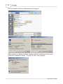
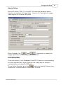
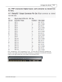
1
V4 Logger
© 2010 OMT Technologies
This manual is copyrighted by OMT Technologies Inc. (OMT) with all rights reserved. Under the copyright laws, this manual
may not be reproduced in any form, in whole or in part, without prior written consent of OMT.
Disclaimer
OMT Technologies Inc. has reviewed this manual thoroughly in order to make it an easy to use guide. All statements,
technical information, and recommendations in this guide and in any guides or related documents are believed reliable, but
the accuracy and completeness thereof are not guaranteed or warranted, and they are not intended to be, nor should they
be understood to be, representations or warranties concerning the products described.
This product has been sold to you subject to the limited warranties set forth in the warranty and license agreement
enclosed with the respective products. Further, OMT reserves the right to make changes in the specifications of the
products described in this guide at any time without notice and without obligation to notify any person of such changes.
Trademarks
LX-44, SC2000, BX-12 and Antex are registered trademarks of Antex Electronics.
VX222, VX820 and Digigram are registered trademarks of Digigram.
MPEG is a trademark of Qdesign.
MPEG Layer-3 audio coding technology licensed from Fraunhofer IIS and Thomson Multimedia.
Microsoft, MS, Windows and MS-DOS are registered trademarks of Microsoft Corporation.
Netware is a trademark of Novell Corporation.
Certain features of this software use software that is delivered under the LGPL license. This license can be found at
http://www.gnu.org/licenses/lgpl.html.
CD ripping uses the AKRIP library. Source code can be found at http://akrip.sourceforge.net.
ID3 identification uses the ID3LIB library. Source code can be found at http://id3lib.sourceforge.net.
All other product names are copyright and registered trademarks/trade names of their respective owners.
Printed: November 2010 in Canada
Document Version: 1.0.0
Publisher
OMT Technologies Inc.
Technical/Graphics
Rick Landry
Special Thanks
Special thanks goes out to all of our customers who contributed their time and effort
into helping us create this document.
Contents
I
Table of Contents
Part I V4 Logger User Guide
1 Overview
1
................................................................................................................................... 2
2 Requirements................................................................................................................................... 3
3 Installation
................................................................................................................................... 5
4 New Features
................................................................................................................................... 15
Repeat Recording
..........................................................................................................................................................
Every Hour
16
Allow Multiple Closures
..........................................................................................................................................................
per Recording
17
Delayed Broadcast
.......................................................................................................................................................... 18
E Series Wheatstone
..........................................................................................................................................................
AOIP Interface Module
21
AXIA AoIP Systems
..........................................................................................................................................................
Interface Module
22
5 Configuration
................................................................................................................................... 24
6 Feed Creation
................................................................................................................................... 41
7 Schedule Creation
................................................................................................................................... 52
8 Histogram ................................................................................................................................... 59
9 Event Log
10 Inventory
................................................................................................................................... 60
................................................................................................................................... 62
11 Appendices ................................................................................................................................... 64
DIO 24H PCI Closure
..........................................................................................................................................................
Card
65
Broadcast Tools..........................................................................................................................................................
GPI - 32 USB Closure Device
84
Broadcast Tools..........................................................................................................................................................
SS4.2/SS8.2 Switcher
97
WDT 500 "Watchdog"
..........................................................................................................................................................
Card
123
© 2010 OMT Technologies
I
1
1
V4 Logger
V4 Logger User Guide
70 channel competition monitoring Logger courtesy of OMT Technologies
© 2010 OMT Technologies
V4 Logger User Guide
1.1
Overview
Version 4 LOGGER
Overview:
Welcome To the Version 4 Logger Guide.
Version 4 represents the 6th generation of Broadcast Software from OMT Technologies.
As always, your feedback is important to us. Please refer to the following contact list for sales,
support and product information.
QA/Product Development:
Rick Landry
[email protected]
Sales/Operations Manager:
Jackie Tetlock
[email protected]
Support Administration:
Brenda Barteaux
[email protected]
OMT Support
800-726-2635
General Office Line
888-665-0501
FAX:
204-783-5805
© 2010 OMT Technologies
2
3
1.2
V4 Logger
Requirements
Version 4 LOGGER
Requirements:
Computer
Description
Minimum
Recommended
CPU
P4 1.5 GHz
P4 2.0 GHz
RAM
512 MB
1 GB
1024 X 768
1280 X 1024
*
Non-Onboard
250 MB
>250 MB
Screen Resolution
Video
Hard Drive space
Screen Resolution is 1280 x 1024 in Version 4.x. ONAIR and ONAIR applications. The minimum hard
drive space requirement is now 250 MB. Previous screen resolution in 3.x and older was 1024 x 768
(for ONAIR) and the minimum hard drive space was 50 MB.
Supported OS
Operating System
Type of Computer
Win XP PRO 32 bit
Workstation
All Media Touch applications running on a workstation require WIN XP PRO at this time. Database
and audio assets that reside on a central server may run 32 or 64 bit server OS based on RAID driver
compatibility.
Sound Cards/Devices
Manufacturer
Model
Audio Science
Driver
5000/8000 series
WDM
MOTU
2408/826/896/24 I/O
WDM
Delta
44/66/1010
WDM
VX 222/442/822
WDM
Antex
LX 44, BX 12. SC
2000
WDM
Lynx
Lynx II, AES 16
WDM
ECHO
Layla 3G, Mia
WDM
Orban
1100
WDM
DigiGram
Realtek/Onboard All
WDM
OMT Software applications will support a wide variety of audio cards provided they have a valid WDM
driver. Multiple cards can be installed using ASI, MOTU and Antex only at the time. Contact OMT
Support if you do not see your sound device listed.
© 2010 OMT Technologies
V4 Logger User Guide
Version 4 LOGGER
Requirements - Continued:
Other
It is recommend having two hard drives in all Media Touch workstations. This allows a separate
drive/array for audio storage and access. A RAID 5 storage array is recommended for dedicated
audio servers and 8 and 12 channel Logger applications. ONAIR computers acting as a server may
also require a RAID 5 array based on the amount of recording or Production units.
* Onboard video may not provide satisfactory performance based on the manufacturer chipset. It is
recommended to use a separate PCI-X or other video card as it will provide better performance
versus onboard video. Most onboard video will perform satisfactorily based on the later video chipset
available.
© 2010 OMT Technologies
4
5
1.3
V4 Logger
Installation
Version 4 LOGGER
Installation:
ftp site information:
Every Media Touch client has an ftp account created with a software purchase. The ftp site,
username, and password are sent out to client provided contact information. If you do not have your
ftp account information or cannot locate, simply contact OMT Support or Support Administration to
obtain.
The ftp site is: ftp://support.imediatouch.com
Once you have successfully logged onto the site, locate the iMediatouch_V4 folder and download all
applicable software that you have purchased. You may download all available software if you desire
as all software products have a 60 day trial installer.
Create a folder on your central audio server or ONAIR workstation acting as a server called “OMT
Programs”. Download the software installers (.exe) of the iMediaTouch_V4 folder to this location.
Placing the installers on the storage array of your central server or ONAIR workstation allows for the
installation of the software to any workstation.
Installation:
Double click on the iMediaLogger_4.0.0_Setup.exe installer.
You will see the Welcome Screen.
© 2010 OMT Technologies
V4 Logger User Guide
Version 4 LOGGER
Installation - Continued:
If your computer passes the minimum requirement screen, the “Next” button will be available. The
System Check will fail the installation if the requirements are not met.
Select the “I agree to the terms of this license agreement” once you have reviewed.
© 2010 OMT Technologies
6
7
V4 Logger
Version 4 LOGGER
Installation - Continued:
Place the appropriate user information into the corresponding fields.
The help file will install by default from the Install Options page.
© 2010 OMT Technologies
V4 Logger User Guide
Version 4 LOGGER
Installation - Continued:
Select number of Logger channels based on your purchase from the Install Options page.
8 and 12 Channel Logger applications can use a significant amount of CPU and RAM from your
computer and there is a warning screen that will appear reminding the user based on the 8 or 12
channel selection form the Install Options screen. Select OK when ready.
The Ready to Install screen will now appear. Select “Install when ready.
© 2010 OMT Technologies
8
9
V4 Logger
Version 4 LOGGER
Installation – Continued:
Logger has a utility called the “Watcher” that will detect the loss of the Logger.exe and restart if
required. This feature is turned off by default and is not normally required. Select “Next” when ready.
You can add Logger to your start by selecting the appropriate start up selection. Select “Next” when
complete.
© 2010 OMT Technologies
V4 Logger User Guide
Version 4 LOGGER
Installation – Continued:
Enable the “Run iMediaLogger” by selecting to place a check mark in the box if you wish to run
immediately following the installation and selecting “Finish”.
You have 60 days upon installation to register your software. If you have Internet access, you can
click on the “Get Password” button from the splash screen. You can also register your software at
www.imediatouch.com and click on the “Support” tab.
© 2010 OMT Technologies
10
11
V4 Logger
Version 4 LOGGER
Installation – Continued:
Setup Wizard
If you are upgrading from any existing version of Logger that is higher than 2.5.6 then clicking on
“Trial” or registering your software and clicking “Next” will start the Logger application as expected.
If this is a new installation of Logger then clicking on “Trial” or registering your software and clicking
“Next” will start the “Setwiz.exe utility as displayed below. Select “Next” when ready.
The Default File location should always be the storage drive or array as this is where the audio files
for local recordings will be stored. Use the “Browse” button to view a suitable drive location through
Windows Explorer. You can change these values later on if you are undecided. Select “Next” when
complete.
© 2010 OMT Technologies
V4 Logger User Guide
12
Version 4 LOGGER
Installation – Continued:
Audio Device Configuration
Select the appropriate channels from the Audio Device Configuration page. Each Logger channel can
consist of a Stereo input channel, Left Channel, or the Right Channel. Only one of the before
mentioned devices can be use for a Logger channel.
E.G. A single channel Logger does not allow three separate recording streams based on the
availability of stereo, left, and right on each device. The user must define only one of the three
available devices for the one channel Logger.
The screen shot below shows left/right channel selection for 4 stereo devices. In this example, I have
installed an eight channel Logger and I am configuring 8 MONO channels for use. Click “Next” once
you have selected the appropriate audio devices.
Network Configuration
© 2010 OMT Technologies
13
V4 Logger
Version 4 LOGGER
Installation – Continued:
The Network Configuration allows what name is to be displayed through the HTML Interface, what
port to assign, and enabling the HTTP service in Logger.
If you do not plan on using the HTML Interface simply uncheck the HTTP Web Services Active box.
This will prevent anyone from accessing the Web Browser through Logger. The port value can be
changed to any suitable or required value if you do not wish to use port 80. Click “Next” when
complete.
Message Logging Options
It is always a good idea to enable all five error messaging options, especially with a new installation
for troubleshooting purposes. Enabling all messaging will display messages showing closure tallies,
IP addresses of people accessing the HTML page, schedule and device errors, etc. By default, only
“Log Error Message” is enabled.
The Event Log location is set to the working folder for iMediaLogger. You can select the desired
location (if different by selecting the “Browse” button and navigate through Windows Explorer to a
suitable location.
Click “Next” when complete.
© 2010 OMT Technologies
V4 Logger User Guide
14
Version 4 LOGGER
Installation – Continued:
Database Setup
The file location is only to be setup if you currently have an iMediaTouch system (ONAIR, MTP, MVT,
etc.) and wish to record spots directly to the database via Logger. This will allow automated and
scheduled playback of pre-recorded items through the Logger software. Leave this field blank if you
are using your Logger as a stand alone unit or use a different radio broadcast software system. Click
“Next” when complete.
To complete the setup wizard, click on the ”Finish” button.
© 2010 OMT Technologies
15
1.4
V4 Logger
New Features
V4 Logger
New Features :
There are several new features in the V4 Logger over 3.1.9 and previous versions.
-
Repeat Recording Every Hour
Allow Multiple Closures per Recording
Delayed Broadcast
E Series Wheatstone AOIP Audio and GPIO Interface
AXIA AoIP Systems Interface
These new features have been requested by our clients and we are pleased to be able to provide this
functionality. The Wheatstone and AXIA AOIP Interface is available for purchase in a separate
module and is further covered in this user guide.
© 2010 OMT Technologies
V4 Logger User Guide
1.4.1
16
Repeat Recording Every Hour
“Repeat this recording every hour”
The repeat function will save a great deal of time and data entry since many top of hour spots such as
News, Weather and Sports can now be entered (scheduled) once and enable the repeat this
recording every hour box.
This feature will automatically set the recording schedule for the same time for each of the 24 hours
and can be easily recognized in the Daily Scheduler window display when enabled with the double
Asterisk.
© 2010 OMT Technologies
17
1.4.2
V4 Logger
Allow Multiple Closures per Recording
“Allow Multiple Closures per Recording”
Allow Multiple Closures per Recording is convenient where multiple closure segment recording are
required for a single scheduled feed event.
Example:
A Logger recorded event requires several closures to occur over time such as a scheduled mic skim.
This feature will now allow multiple closures to occur over a set scheduled time.
© 2010 OMT Technologies
V4 Logger User Guide
1.4.3
18
Delayed Broadcast
A new feature has been added to Logger (Version 4.1 and higher) called "Delayed Broadcast". This
feature is designed to allow only the ONAIR application to play back a Logger file during recording.
This is the only window of time where the .vis file from a Logger based recording cannot be updated is
when the Logger is still recording an audio spot that the ONAIR application is actively playing. ONAIR
can play back an audio spot that Logger is recording provided that the Logger has been recording the
spot for a minimum of one minute and both "Delayed Cueing" in the ONAIR and "Delayed Broadcast"
in the Logger schedule have been enabled.
With Delayed Broadcast unchecked, the file cannot be shared (with applications other than ONAIR)
and the Logger application has exclusive access to the recording.
The flow chart and screen shot on the following pages outline the theory and locations in both
application on how to enable and setup.
© 2010 OMT Technologies
19
V4 Logger
© 2010 OMT Technologies
V4 Logger User Guide
© 2010 OMT Technologies
20
21
1.4.4
V4 Logger
E Series Wheatstone AOIP Interface Module
Version 4.1 of Logger and higher now have the ability to Interface both Audio and GPIO with the E
Series (88a,d, and e) Wheatstone AOIP system.
A separate module/installer is now available and can be purchased through sales at
[email protected] or phone 888-665-0501.
Once the Wheatstone Interface module is installed, an additional device listing for the Wheatstone
device will appear under the "Hardware" tab of the Logger Configuration page. The port is predefined and the user simply place the IP address of the Wheatstone "Blade" to provide
communication.
© 2010 OMT Technologies
V4 Logger User Guide
1.4.5
AXIA AoIP Systems Interface Module
Logger 4.1.2 and higher now have the ability to interface with both GPIO and audio routing the AXIA
AoIP system.
A separate module/installer is now available and can be purchased through sales at
[email protected] or phone 888-665-0501.
Once the AXIA Interface module is installed, an additional device listing for the AXIA device will
appear under the "Hardware" tab of the Logger Configuration page. The port is pre-defined (9500)
and the user simply place the IP address of the AXIA to provide communication.
IMPORTANT: AXIA must be set to 48,000 Sample Rate under Audio Devices.
© 2010 OMT Technologies
22
23
V4 Logger
NOTE: If you do not have a valid license you will not be able to use the AXIA Interface
© 2010 OMT Technologies
V4 Logger User Guide
1.5
24
Configuration
V4 Logger
Configuration :
The above screen shot shows the “Status” screen immediately following the start of the Logger
software. The example displayed is an 8 channel version using an Echo Layla 3G 4 Stereo/8 mono
audio device. Channels that are not viewable directly from the main status tab can be accessed by
using the scroll bar on the right hand side of the screen. The “status” tab is the default main screen
and displays current recording activity or inactivity. The audio devices/channels are displayed in the
left hand column and each meter represents each channel of the Logger you have configured or
purchased.
Example:
8 meters displayed in the left hand column would signify an 8 channel Logger. The meters are visible
at all times regardless of the “tab” selected. If you have only configured 6 of the available 8 channels
in an 8 channel Logger application, then only 6 meters will be displayed.
NOTE: The meters will only display activity under a scheduled record. The meters will not display
any levels unless a feed and scheduled item has been created. It is recommended that a full time
logging schedule is created when setting or adjusting levels on a specific feed element.
File
At the top right hand corner of the status (main) screen there is a “File” drop down that will allow the
user to select “Exit” to quit the Logger program.
© 2010 OMT Technologies
25
V4 Logger
V4 Logger
Configuration - Continued:
Tools
The Tools dropdown will allow the user to select between “Configuration” and “About”. The “About”
drop down will display the version information of the Logger Software.
Configuration
The configuration window appears after you have selected “Tools” then “Configure” from the Logger
main screen.
The first tab or page displayed from the Configuration window is the “Files” tab. Under Files, several
options are available such as Log File Names, Destinations, and enabling the “Connect to OMT
Database” including location path.
© 2010 OMT Technologies
V4 Logger User Guide
26
V4 Logger
Configuration - Continued:
Log File Names
The default Log File Name is displayed in the above screen shot. The definitions of the characters
are explained below:
$f
=
$y =
$m =
$d =
$h =
$n =
$s =
\
=
Clear =
Feed ID
Year
Month
Day
Hour
Clip No.
Second
Sub Dir
Removing all default or custom naming convention back to the default destination.
The list of invalid characters is displayed to the right hand side of the Log File Names window.
You can also create custom Log File Names by selecting the quick link buttons provided that each
represents one of the functions that have been previously defined.
The corresponding path will be displayed under “Example” as demonstrated in the screen shot above.
The path will change as you add or select new definition buttons. You can clear the default or custom
Log File Name by selecting “Clear”. It is recommended that you use the pre-defined buttons to create
a custom file name “macro”.
© 2010 OMT Technologies
27
V4 Logger
V4 Logger
Configuration - Continued:
Destinations
OMT recommends that all workstations running our software contain a separate OS and storage hard
drive. This will dramatically improve performance as the OS drive is not trying to write or access the
disk when write audio files to a specified storage location. With two drives one is always dedicated to
the operating system while the storage drive is always recording digital files on to the storage drive.
This location is referenced during the setup installation of Logger. However, additional locations can
be added by selecting the “Add” button. “Edit” will allow the recording location to be changed after the
initial setup and configuration. “Remove” will remove the default destination entry.
Selecting “Add” brings up the following screen.
The title can be changed to any suitable name while the location can be selected by clicking on the
“Browse” button. “New Destination 1” is the default Title and this can be changed to any suitable
name that the user desires.
Highlight on a destination in your list then select “Edit” and you will see the following screen.
Browse to a suitable storage location and click on “OK” when complete.
NOTE:
USB drives are not recommended by OMT as an additional storage location based on their slower
read/write times in comparison to an EIDE or SATA II internal hard drive. Some clients have had
success using USB drives and we leave this to the discretion of the Logger user.
© 2010 OMT Technologies
V4 Logger User Guide
V4 Logger
Configuration - Continued:
Connect to OMT Database
Only enable this feature if you have a Media Touch ONAIR system and wish to record directly to the
database for later play out or editing.
Use the
button to browse to a suitable location. The Projdata.dbf file is located at the root of
the O:\ drive in most cases and the location created on the audio server or ONAIR acting as a server
by OMT when integrating systems in house.
Administration
There are several configurable sections under Administration; Server Settings, Event Logging,
Maintenance, and Enable Admin Email.
© 2010 OMT Technologies
28
29
V4 Logger
V4 Logger
Configuration - Continued:
Server Settings
This will display the version of the Logger software and allow the user to change the name that will be
displayed on the Server Identity displayed in the built HTML page in Logger.
Event Logging
The General Status is the only item that is enabled by default in the Logger application. However, it is
strongly recommended that the user enable all event logging to assist in schedule tracking, closure
and audio validation, and potential troubleshooting.
General Status
Feed Related
Network Related
-
Serious Error
-
Schedule Related
-
Displays completed events
Displays Feed names associated with start, stop of recordings
Displays the IP address of any computer accessing the HTML
Interface
Displays failed recordings, error codes, audio device failures,
etc.
Displays schedule failures based on conflicts, incomplete
recordings, etc.
The file path is the location of where the Logger event log will be created and updated. This location
can be changed form the default to suit the user requirements.
Maintenance
The Enable File Cleanup is active and set to 30 days based on Canadian CRTC requirements. This
value is known as the “Global” file cleanup setting and the value can be increased to 999 days or
decreased to a minimum of 1 day.
NOTE:
Be sure to check the amount of storage on your secondary or storage array as increasing the Global
file cleanup settings past 30 days can require a significant amount of hard drive space depending on
the local recorded format. There could be a danger of filling up your hard drive causing the Logger
application to hang or fail.
© 2010 OMT Technologies
V4 Logger User Guide
V4 Logger
Configuration - Continued:
“Delete Files” is enabled by default along with the 30 day setting and the user can also enable the
“Move Files to” feature to move the files to a user definable location. This would be a network or
additional storage drive letter under a standard windows file location and not through a URL or ftp
string.
To set the location of the Move File to feature, select the
path window.
button directly to the right of the file
Enable Admin Email
This feature is not enabled by default. To use this feature, select the enable box to activate then
place the appropriate information including desired email address, outgoing server name and login
and password for the email account.
Audio Devices
© 2010 OMT Technologies
30
31
V4 Logger
V4 Logger
Configuration - Continued:
The audio devices are listed in the display window and will show all WDM based audio devices
installed in Windows. You can select any or all listed devices and are limited the number of channels
of your Logger application.
When you have selected the maximum number of devices for the amount of Logger channels
available, any remaining audio device selections will become grayed out.
NOTE:
Any device or channel configuration change will require a restart of the Logger application.
Recording Sample Rate
The default rate is 44100. 32000 and 48000 can also be selected where applicable from the drop
down tab to the right of the frequency display.
Audio Settings
© 2010 OMT Technologies
V4 Logger User Guide
32
V4 Logger
Configuration - Continued:
Perform Silence Detection
The above screen shot displays the “Perform Silence Detection” section. This is enabled by default
and will flash the “Silence” warning from the Record/Meter section on the left hand column of the
Logger application independently for each audio channel.
If you have a closure device installed such as the DIO 24H PCI card in the following example, you can
assign a closure for either “When any channel is silent” or “When no channel is silent”. Select the
“Edit” box directly to the right of both function and the select the appropriate pin based on your
installed closure device. You can enable one of the two available functions if desired.
The “Allowed Silence Threshold” does not reference from a specific zero reference point. To
accurately set both the “Allowed Silence Threshold” and “Auto Trim” levels, use a known or fixed
output such as a reference tone or tone generator.
Auto Trim
NOTE:
It is strongly recommended NOT to use the auto trim feature on a large number of scheduled
database recordings as this will place a significant amount of overhead on the Logger computer,
especially with 8 and 12 channel versions. Use discretion when applying this feature to ensure
reliability and functionality.
© 2010 OMT Technologies
33
V4 Logger
V4 Logger
Configuration - Continued:
Hardware
Switcher Options
Once you enable the Switcher field, there are currently four selections to choose from:
NOTE: The code set for the SS4.2 and SS8.2 are the same so you can still support a SS4.2 by
selecting the SS8.2 drop down. The ACS8.2 will also work using the SS8.2 dropdown.
There are also 4 selectable baud rates that are COM port specific:
© 2010 OMT Technologies
V4 Logger User Guide
34
V4 Logger
Configuration - Continued:
Most Broadcast Tools Switcher and closure devices can operate at 38400 and this will decrease
“latency” in processing closure or audio routing commands.
NOTE: OMT configures Broadcast Tools Switchers to operate in “Interlock Mode” versus “Mix” mode
with the ONAIR application. This is to prevent simultaneous audio content from multiple sources
being recorded through the switcher device.
There is additional Broadcast Tools configuration assistance in the Appendices of this guide.
Enable the “Invert Closures” if you logic appears to be reversed.
E.G.
The event log in Logger will display all closures when enabled and you may see the correct pin
closure but the logic may be reversed. It is assumed that “high” is active or on and “low” is inactive or
off. If you required “low” to be active, enable the “Invert Closures” and this will reverse the logic.
Closure Devices
If you have previously installed a DIO 24H Measurement Computing card then you only have to
enable the device from this section as the setup is automatic.
Although the SRC – 32 is no longer manufactured there are a great number of clients who still use
this device and therefore we still provide interfacing. Enabling the SRC – 32 closure device will also
control the GPI – 32 USB based closure device. Later versions of V4 will also have support for the
SRC – 16.
The WDT 500 Watchdog card is a PCI based card that will monitor PCI bus activity and output a
closure in the event PCI activity is halted. The closure is generally connected the computer’s reset
wire on the motherboard and this in turn reboots the PC. There is a separate WDT 500 installation
guide later on in the appendices of this Logger guide.
© 2010 OMT Technologies
35
V4 Logger
V4 Logger
Configuration - Continued:
Time Services
You can apply a specific time server to update the Logger PC clock based on two formats.
NTPv3:
Select “Add” from the bottom of the Time Servers windows and you can select NTPv3 and a drop
down list of available NTP servers to choose. You can also supply your own custom NTP server
address.
Time
You can also use the Time Protocol and supply the corresponding address to obtain updates.
© 2010 OMT Technologies
V4 Logger User Guide
V4 Logger
Configuration - Continued:
Enable the “Set system clock” if you have selected a time server and this will allow the user to select
the time when the Logger PC updates, the time window, and the additional of a time offset is desired.
The “Set clock” drop allows for two time update choices:
The Time window or “if more the x seconds out” drop down is user definable from 0 to 60 seconds.
The “Apply an offset of x seconds” is user definable from -100 to 100 seconds with 1 second
increments.
Enable the “Provide NTP service is you are update with an NTP based time server and you wish to
use the Logger PC as the time base.
The “Edit” and Remove” buttons will highlight once you have added a Time server.
© 2010 OMT Technologies
36
37
V4 Logger
V4 Logger
Configuration - Continued:
Archives
The archives section will allow the user to send scheduled recorded audio based on feed to a specific
ftp location. This will also allow the user to configure there WebSecure+ ftp account based on IP
address.
Select “Add” to proceed and you will see the screen below.
Create any desired name for the ftp site or leave as the default naming convention. The host name
can be DNS based or IP address. If you are using an DNS name or IP address, no UNC naming
convention (\\) is required. Port 21 is the standard ftp port and this can be set to any desired value.
Username and password for the WebSecure+ unit is mts and 1234 by default. The “Path” would be
left blank if you are configuring for WebSecure+ and the user can set any folder path desired for
custom ftp sites. Enable the “This is a WebSecure Upload” to transfer audio to the WebSecure+
appliance and leave unchecked if this is a standard ftp site.
© 2010 OMT Technologies
V4 Logger User Guide
V4 Logger
Configuration - Continued:
Below is an example of a typical WebSecure+ Archive configuration screen:
Below is an example of a standard ftp archive site configuration:
“ftp archived” audio is dependant on Internet connectivity and bandwidth. The larger number of ftp
sites or the greater the size of the recording, the longer it will take for audio to arrive at the specified
location.
Plan and calculate the amount of audio you intend to transfer based on these parameters. The
Logger will “cache” audio file transfer but only to a limited amount based on PC memory, speed, etc.
and adds delay to the files arrives at the specified location.
WebSecure+ users are generally not affected by the amount of file transfer where the WebSecure+
appliance is located within the LAN of the Logger PC. The same rules/limitations would apply where
the WebSecure+ unit is located offsite and connected via WAN or Internet.
The WebSecure+ User Guide can be found at www.imediatouch.com/help
© 2010 OMT Technologies
38
39
V4 Logger
V4 Logger
Configuration - Continued:
HTML
General Config
Under “General Config” the HTTP Service Port can be enabled and the Port value set.
Color Settings
Use the
box to select a specific color and change the appearance of the HTML page to the
desired effect.
© 2010 OMT Technologies
V4 Logger User Guide
40
V4 Logger
Configuration - Continued:
Content
Any or all of the above content features can be enabled/disabled and this is a global feature with
respect to the HTML page and not feed specific.
Metafile Configuration
The user can change the information displayed within the HTML page by editing the field in the above
screen shot.
$F – Feed Name
$D – Day of the week
$d – Description field in the edit window under Scheduler
Below is a screen shot of the standard HTML through Logger. This page can be access by placing
the static IP address of the Logger PC into Internet Explorer browser from any LAN computer on the
same IP range. We currently do not have support for the Fire Fox browser. If you are using IE 8, you
may need to enable “compatibility mode” to stream audio cuts.
© 2010 OMT Technologies
41
1.6
V4 Logger
Feed Creation
V4 Logger
Feed Creation:
Once the Logger Configuration has been completed, the user can now define feeds and recording
schedules. A Feed item contains the format of the recording, audio device or channel and other
custom settings.
To create a feed, click on the “Add” button at the bottom right corner of the Feeds tab.
The following New Feed Entry edit window will appear.
NOTE: Characters that are not allowed are displayed at the bottom of the New Feed Entry Edit
screen.
© 2010 OMT Technologies
V4 Logger User Guide
42
V4 Logger
Feed Creation - Continued:
You can use the default name or a custom name of your choice following the rules on non-valid
characters displayed previously. Click “OK” when complete.
Feed Properties
Edit the Feed Properties field to remove the default naming and placement of “New Feed”. Perform
this prior to saving or you will have to delete and recreate the feed as this cannot be change once it
has been saved.
File Properties
Default destination is the location of the audio recordings that was previously setup under the Logger
Configuration. Enable “Use WebSecure Filename Macro” if you are connected to a WebSecure+
appliance and require the feed to be archived to the unit.
Enable the “Use Custom Filename Macro” if you require a custom naming convention and location for
the audio recorded through Logger.
Use the button panel above the custom name file path to generate the desire custom file naming
convention. This will ensure valid characters are used in the file name path.
Below is an example of Year, Month, and Day naming convention.
© 2010 OMT Technologies
43
V4 Logger
V4 Logger
Feed Creation - Continued:
Audio Properties
The above screen shot shows the default display prior to configuring audio parameters. The channel
displayed will be the default Windows channel setup under Playback and Record options. This setting
is located in the Control Panel under Sounds and Audio devices and located under the “Hardware”
tab. Select the dropdown to the right hand side of the Channel field to select any available channel.
The above screen shot shows 8 available devices as I have configured an 8 channel Logger for this
example. 8 Stereo channels could also have been configured or a combination that would add to 8
devices and would display three choices per device if enabled.
Format
There are 7 formats of audio recording type available through Logger and can be accessed in the
dropdown tab directly to the right of the Format field.
NOTE: You will require a proprietary Dolby AC3 decoder to play audio recorded under this format.
This is generally used for audio recorded underneath video. MPEG layers 1,2 and 3 are available
along with PCM, Real and WMA format.
© 2010 OMT Technologies
V4 Logger User Guide
V4 Logger
Feed Creation - Continued:
Once you have selected a suitable recording format you can now select the recording parameters
under Channels, Sample Rate, and bitrate.
Choose between Stereo and Mono:
Sample Rate:
NOTE: Consumer or onboard sound cards will generally only work under 44,100. If you are using a
Sample Rate other than 44,100, check with your sound card provider to ensure proper operation.
Bitrate: (Under 44,100 Mono)
Under 44,100 Stereo:
The amount of Disk space required based on the user selections will be immediately updated and
displayed in the “Disk Space / Week” display.
© 2010 OMT Technologies
44
45
V4 Logger
V4 Logger
Feed Creation - Continued:
Closure and Switcher Options
Default Destination:
This section allows the user to setup closures and/or audio routing based on the device that has
previously been configured under Logger Configuration. There are four sections that can be
configured:
-
Input Closures
Output Closures
Pause Closures
Switcher/Serial Devices
OMT Database Destination:
If you have selected the OMT Database as the default destination for your feed item then the audio
format is not user definable as it is based on the category you have selected and its corresponding
format. The same categories that are available through Production will be displayed in the category
drop down.
There are 7 sections available through the OMT Database selection under Closure and Switcher
Options.
© 2010 OMT Technologies
V4 Logger User Guide
46
V4 Logger
Feed Creation - Continued:
-
Input Closures
Output Closures
Split Closure
Pause Closures
Switcher/Serial Devices
Options
Input Closures
Click on the
box directly to the right of the Start or Stop display field to select from a list of
available and previously configured closure devices.
The parallel port (if present or enabled) is the default device displayed. Valid input closures for the
parallel port are as follows:
Pins 2 – 13 and 15 are input closures. (Dry contact)
I have configured a DIO 24H card from Measurement Computing for this example and it is available
through the drop down list along with the parallel port as a valid closure device.
The DIO 24H card provides 16 input and 8 output closures.
NOTE: The DIO 24H card can only provide “static” or “latched” output closures. Check with the
device that you are sending output closure to with DIO card and ensure that static or latched closures
can be accepted versus momentary.
© 2010 OMT Technologies
47
V4 Logger
V4 Logger
Feed Creation - Continued:
Logic for the incoming closure can be based on a “low” or “high” condition.
When you have applied the desired closure and logic, click “OK” and the result will be placed in the
Start or Stop display window.
The user can generally save on the number of required closures by selecting one closure with two
logic conditions to perform mic skimming, time based recordings, etc on a single feed.
Output Closures
Click on the
box directly to the right of the Start or Stop display field to select from a list of
available and previously configured closure devices.
The parallel port (if present or enabled) is the default device displayed. Valid output closures for the
parallel port are as follows:
Pins 1, 14, 16, and 17 are output closures and will require a “pull up” circuit to drive a relay.
Logic for the output closure can also be based on a “low” or “high” condition.
© 2010 OMT Technologies
V4 Logger User Guide
48
V4 Logger
Feed Creation - Continued:
Once you have completed selecting the desired output closure pin assignment, the display in the
output closure window will appear similar to the input closure window.
Broadcast Tools SS4.2, SS8.2 ASC 8.2, and the SS16.4 all contain 16 input closures and 8 output
closure that can also be assigned to either the Input or Output closures tab.
For Input:
For Output:
The Broadcast Tools Switcher would have been previously configured under the Logger Configuration
covered earlier in this guide.
Split Closures
NOTE:
The Split Closure function from the Feeds section of Logger requires an OMT database. This feature
cannot be used with a feed that has been configured to the Default Destination or a “Stand Alone”
Logger. It must be used with an OMT automation system/database.
© 2010 OMT Technologies
49
V4 Logger
V4 Logger
Feed Creation - Continued:
To configure the split closure, select the
box to the right of the split file closure display and select
the appropriate closure device and pin assignment.
Under “Split Delay”, set the desired time for the Logger to “wait” until the recording resumes. When
configuring your pre-recorded satellite or external event, this will be based on the provider schedule
clock that outlines the duration of the commercial stopset.
NOTE: Different length wait or stopset times can be scheduled under the “Scheduler” section outlined
later in this guide.
Pause Closure
The Pause feature acts the same as the “old school” cassette or reel to reel machine where a remote
switch closure would continue the recording and when open would stop the recording but leave the
device in a record/pause mode. The end result is a recording that does not contain minutes of dead
air when using closure based recordings such as mic skims.
Any valid closure device can be assigned for the incoming closures as with the previous Input, Output,
and Split closure functions. There is also a delay with an adjustable value of 0 to 5000 ms (5
seconds) to compensate for the inherent delay on WAN or Internet based audio feeds.
The “Pause on Start” can be enabled to place the feed item in record/pause mode initially.
© 2010 OMT Technologies
V4 Logger User Guide
V4 Logger
Feed Creation - Continued:
Switcher/Serial Devices
If you have configured a BTools switcher, Klotz router, or raw serial device under the Logger
Configuration page, then it will be available under the Switcher/Serial Devices tab for selection.
To configure the Switcher/Serial Device, select the
box to the right of the Switcher/Serial Device
display and select the appropriate device and audio routing assignment.
NOTE: The Switcher/Serial Device Edit screen provides two operations for both “On Start” and “On
Stop”. This eliminates additional audio routing or muting where required when ending a feed item.
An example of a two operation assignment is displayed below.
© 2010 OMT Technologies
50
51
V4 Logger
V4 Logger
Feed Creation - Continued:
Assign the appropriate audio channels for both input and output for both Start and Stop functions.
Select
when complete.
Options
The user can place and EOM or Stop marker by enabling the feature and select a value between 0
and 999 seconds for either function.
This would be most commonly applied to show segments where log based sweepers or jingles are
required to cross fade over the recorded segment.
© 2010 OMT Technologies
V4 Logger User Guide
1.7
52
Schedule Creation
V4 Logger
Schedule Creation:
There are three main sections to the Schedule tab where the user can create and edit under Logging,
Daily, and One Shot schedules.
Logging
Logging is most commonly used for off air signal recording for CRTC requirements, mic skims, and
“best of” shows. To create a new Logging Scheduled item, right click anywhere in the Logging
window and select “Add”.
This should take you to the edit window where you can select a feed item previously created, provide
a description, and set the file splits from 1 minute to 2 hours in length.
NOTE:
Logging will only allow feed items that are recorded to a Default Destination. OMT Database
Recordings are scheduled through the Daily section. Only Logging scheduled recordings set for the
Default Destination can be sent to a WebSecure+ appliance and are applied under the “Feeds”
section.
© 2010 OMT Technologies
53
V4 Logger
V4 Logger
Schedule Creation - Continued:
Select the
button to provide either MP3 ID3 V2 tagging of MP3 recorded audio
or CART information for MP2/WAV recordings.
NOTE:
XML information can also be applied if desired to a Daily Schedule recording when “archive” is
enabled.
E.G.
ID3 V2 or CART information will be embedded into the recording (MP3 or MP2/WAV) if the CART/ID3
checkbox is enabled.
© 2010 OMT Technologies
V4 Logger User Guide
V4 Logger
Schedule Creation - Continued:
The following example has been tagged with ID3 V2 information as this is a MP3 recording and is
being played out of Windows Media Player 9. You can see the title/artist information being displayed
along with the album.
Windows Media Player 11 is displayed below with the same track and information.
You can also edit an existing Logging scheduled item once created by right clicking in the Logging
window and select “Edit”. Copy and Delete functions are also available.
© 2010 OMT Technologies
54
55
V4 Logger
V4 Logger
Schedule Creation - Continued:
Daily
Daily scheduled recordings allow for pre-recorded satellite events with “split on closure” feature,
pause, static cut number assignments and 0.5 second EOM placement. Both Default Destination and
OMT Database locations can be used under the Daily section.
To create a Daily scheduled item, right click in the Daily schedule window and select “Add”.
There will be several options available based on a Default Destination or OMT Database recording.
Default Destination spots are recorded to the local storage drive specified and therefore, cannot have
a cut number applied, no auto trim, no split closures or 0.5 EOM applied.
On OMT Database recordings, the split file function is disabled and the “Archive” function is disabled.
Default Destination
OMT Database
© 2010 OMT Technologies
V4 Logger User Guide
56
V4 Logger
Schedule Creation - Continued:
Break down of the Daily Schedule Edit Window:
Item Type: This will be set to Daily as the edit window has been opened from the Daily section.
Use Feed: All feeds previously created are selectable from the drop down.
Description: The user can create any name for the Daily scheduled item. The default is “New
Schedule Item”.
Tag/XML: This was outlined in the Logging section where ID3/CART and XML output can be
enabled.
Start Time: The time displayed will always be the current time upon opening the edit window. Set
the desired start time for your recording to begin.
Duration: Place the desired value for the length of your recording.
Stop Time: This will be automatically calculated based on your start time and duration. The screen
shot below displays the same start and stop time since no duration has been placed.
Set Maximum Record Time: This will set a duration where recordings based on closure can occur
from a specific start point. Defining the Maximum record time will allow a floating closure to occur and
record to the specified amount. This is commonly used for recording National commercials/spots from
syndicated programming that uses floating closures.
© 2010 OMT Technologies
57
V4 Logger
V4 Logger
Schedule Creation - Continued:
Repeat this Recording: This will automatically schedule same time spots for each hour of the day at
the same start time. This is very useful for top of hour news recordings, sports, etc.
Allow multiple closures per hour: This will allow the same closure assignment to be active within a
specified record window. This is very useful for hour specific mic skims, fixed or same length floating
closure recordings, etc.
Active Days: This will allow the user to select any or of the days of the week and provides a M-F
quick button for assigning and a “NONE” button to clear all entries.
Split File: This will allow the user to have the audio recording end and restart at a specific time and
duration. File splits occur based from the top of hour time and NOT from when the recording actually
starts if different than top of hour.
NOTE: This feature is not active under an “OMT Database” feed item and will be “grayed out”.
Archive To: The Archive section will allow recordings to be recorded locally, to Web Secure+ and to
a pre-configured ftp location.
This feature is not available on OMT Database feed items and will be “grayed out”.
Always Start Recording At: The will allow the user to place a four digit cut number based on the
category selected through the feed item under the OMT Database location. This number will always
be recorded to every time the daily scheduled recording runs.
Auto Trim When Recording Has Completed: This can be used to automatically remove dead air or
silence from the start or end of a Logger recording when using an OMT Database feed item.
© 2010 OMT Technologies
V4 Logger User Guide
58
V4 Logger
Schedule Creation - Continued:
Use Schedule Split Closure Delays: This will take the time value placed under the “Split Closure”
tab of the Feeds section.
If no value has been placed in this field and the Use Schedule Split Closure Delay is enabled, it will
take the time information from the “Set Delay” Time log.
Click on the “Set Delay” button and the following time schedule will appear.
Place the desired time for the first commercial stop set/break under the Min and Sec window and click
“Add”. Continue this process following your satellite schedule clock until all required breaks (up to 16)
have been filled.
Set 0.5 EOM: This feature can be used for recording music beds and placing a 0.5 EOM on the cut
which will provide a means of having pre-recorded beds to play underneath voice or other log
scheduled content in the ONAIR. This was also useful when using Card Mapping and “slate marking”
recordings prior to having the ability to set specific closure record delay times.
© 2010 OMT Technologies
59
1.8
V4 Logger
Histogram
V4 Logger
Histogram:
The Histogram provides a waveform time based graph to display when audio (and relative level) was
present and at what time. This is particularly convenient when validating an audio source such a
satellite feed, to confirm audio was present at a specific time. This is also a good diagnostic tool to
verify if audio is being received on any channel.
The start time is displayed in the bottom right hand corner of each Histogram window while the
channel information is displayed on the left. To view all information on long file recordings, there is a
scroll bar underneath each window to allow the user to scroll from start to current or finish time.
The left channel as displayed above is plotted in a blue color while the right is displayed in red.
© 2010 OMT Technologies
V4 Logger User Guide
1.9
60
Event Log
V4 Logger
Event Log:
The Event Log is your primary source for verification of recordings, closures, audio routing and error
reporting. It is highly recommended that Logger users enable all event logging previous covered
under the Logger Configuration of this guide to ensure all event logging is posted. This will assist in
troubleshooting and validation for new Logger clients.
The screen shot above shows the event log and the Logger start up sequence verifying all available
audio streams and devices while also verifying all closure and switcher devices that are configured.
When all event logging is enabled, any error message will be posted to the event log for easy
identification.
The event by default resides in the C:\Program Files\iMediaWave\iMediaLogger folder and be
configured to be written to any folder location. After several months or years of operation, it is a good
idea to “houseclean” these event logs as they can take up a great deal of space over a long period of
time. The log itself can be opened using Notepad or WordPad and is written in a .LOG format.
© 2010 OMT Technologies
61
V4 Logger
V4 Logger
Event Log - Continued:
The following log file displayed below shows a successful Logger startup sequence. This particular
Logger has a SS16.4 BTools switcher connected.
09/12/23 - 10:46:45
09/12/23 - 10:46:45
09/12/23 - 10:46:45
09/12/23 - 10:46:45
09/12/23 - 10:46:45
09/12/23 - 10:46:45
09/12/23 - 10:46:45
09/12/23 - 10:46:45
09/12/23 - 10:46:56
09/12/23 - 10:46:56
09/12/23 - 10:46:56
09/12/23 - 10:46:57
COM1 9600 baud
09/12/23 - 10:46:57
09/12/23 - 10:46:57
09/12/23 - 10:46:57
09/12/23 - 10:46:57
09/12/23 - 10:46:57
09/12/23 - 10:46:57
-
[STATUS]*************** iMediaLogger Booting ***************
[STATUS]iMediaLogger v4.0.0
[STATUS]OS Version 5.1
[STATUS]Reentrant Device Recording Allowed
[STATUS]Boot: Enumerating formats
[STATUS]Boot: Initializing closures and tallys
[STATUS]Boot: Initializing Auto File Trim
[STATUS]Boot: Creating Time Servers
[STATUS]Boot: Intializing network services... HTTP (Port 80)
[STATUS]Boot: Rebuilding HTML
[STATUS]Boot: Initializing Switchers
[STATUS]Switcher: Enabled Broadcast Tools SS16.4 Switcher at Device 0,
-
[STATUS]InventoryManager::Purging Files Thread started
[STATUS]Inventory Delete Count 0
[STATUS]ScheduleManager::Start() succeeded, schedule manager started OK
[STATUS]Archive Manager::Starting
[STATUS]AutoFileTrim::Stop() succeeded
[STATUS]AutoFileTrim::Start() succeeded
Below is the event logging of OMT Database recordings from various sources using a BTools
switcher. Items that do not record successfully will post an error message and code for identification.
09/12/23
ready
09/12/23
10:55:01
09/12/23
09/12/23
ready
09/12/23
11:05:01
09/12/23
ready
09/12/23
11:03:01
09/12/23
- 10:52:57 - [SCHEDULE]Schedule item at Every day at 10:53:00 - feed 'abc Port D'
- 10:52:57 - [SCHEDULE]Item activated: 'Wed Dec 23 10:53:00 2009' to 'Wed Dec 23
2009'
- 10:55:01 - [STATUS]Virtual record stop of feed 'abc Port D' on device 100
- 10:59:57 - [SCHEDULE]Schedule item at Every day at 11:00:00 - feed 'abc Port A'
- 10:59:57 - [SCHEDULE]Item activated: 'Wed Dec 23 11:00:00 2009' to 'Wed Dec 23
2009'
- 10:59:57 - [SCHEDULE]Schedule item at Every day at 11:00:00 - feed 'FOX SPORTS'
- 10:59:57 - [SCHEDULE]Item activated: 'Wed Dec 23 11:00:00 2009' to 'Wed Dec 23
2009'
- 11:00:00 - [STATUS]Switcher Connect 7:0
HTML access based on IP address can be tracked and monitored through the Event Log.
10/02/04 - 11:03:24 - [NETWORK]File Sent: C:\Program
Files\iMediaWave\iMediaLogger\webdata\published\index.html: 227 bytes
10/02/04 - 11:03:24 - [NETWORK]Request complete [1] from [192.168.1.12]
10/02/04 - 11:03:24 - [NETWORK]Connection [1] from [192.168.1.12]
10/02/04 - 11:03:24 - [NETWORK]File Sent: C:\Program
Files\iMediaWave\iMediaLogger\webdata\published\menu.html: 751 bytes
10/02/04 - 11:03:24 - [NETWORK]Request complete [1] from [192.168.1.12]
10/02/04 - 11:03:24 - [NETWORK]Connection [1] from [192.168.1.12]
10/02/04 - 11:03:24 - [NETWORK]File Sent: C:\Program
Files\iMediaWave\iMediaLogger\webdata\published\main.html: 574 bytes
10/02/04 - 11:03:24 - [NETWORK]Request complete [1] from [192.168.1.12]
10/02/04 - 11:03:24 - [NETWORK]Connection [1] from [192.168.1.12]
10/02/04 - 11:03:24 - [NETWORK]Request complete [1] from [192.168.1.12]
© 2010 OMT Technologies
V4 Logger User Guide
1.10
Inventory
V4 Logger
Inventory:
The Inventory tab in Logger will display all locally recorded audio. This is the same information that
can be viewed through the HTML interface for LAN based workstations.
The “Selected Inventory” view can be adjusted by moving the mouse over the top line of the selected
inventory window until the “double lines” appear within the mouse pointer. Right click and hold and
“pull up” to the desired position.
© 2010 OMT Technologies
62
63
V4 Logger
V4 Logger
Inventory - Continued:
The user can sort the available inventory based on Feed Name, Year/Month or Day. All content will
be loaded by default when the Inventory tab is first accessed. The Inventory list is not preloaded upon
selecting the Inventory tab and therefore will take some time to load a large inventory. This is by
design to remove unnecessary overhead with continuous inventory updating on the Logger
application, particularly with 8 and 12 channel applications that require a significant amount of the
computer’s resources.
The example below shows inventory recorded for a specific feed, day and year/month.
© 2010 OMT Technologies
V4 Logger User Guide
1.11
Appendices
The following "How To" guides are also available from our website at www.imediatouch.com/help
© 2010 OMT Technologies
64
65
V4 Logger
1.11.1 DIO 24H PCI Closure Card
“HOW TO” SERIES
2.6.X, 3.X and 4.X
SETUP WITH THE DIO – 24H MEASUREMENT COMPUTING PCI CARD
Revised February 2010
© 2010 OMT Technologies
V4 Logger User Guide
Setup for the DIO – 24 H card and iMediaLogger
The DIO – 24H card requires 3 – 2.2K 9 Pin SIPS (Pull up resistors) and a
5 volt DC power source if using output closures to drive relays or logic
circuits. The software for the DIO card is the InstaCal software and is
available for direct download at:
http://www.measurementcomputing.com/download.htm
You can install the DIO card prior to installing the InstaCal software and
simply cancel the Windows installer when it appears after reboot. To
install the InstaCal software:
-
Download the “InstaCal” software by selecting clicking on the
above link. You can click on the highlighted link from the
download section shown in the screen shot below.
You will see this screen after clicking on the “InstaCal” link.
© 2010 OMT Technologies
66
67
V4 Logger
Find a suitable location to download the program.
After saving to a known location, double click the icalsetup.exe file and
follow the installation steps. It is OK to “Run” the program.
© 2010 OMT Technologies
V4 Logger User Guide
Windows XP has a built in WinZip extractor and you should see the
following screen. Proceed by clicking “OK”.
Now click on “Setup”.
The files will extract and then you should see the following screen.
Click “Next” then you will see the screen below.
© 2010 OMT Technologies
68
69
V4 Logger
If the location is suitable, click “Next” then you should see the following
screen.
Click “Install”
© 2010 OMT Technologies
V4 Logger User Guide
You should see the following screen when completed.
After the installation is complete you will be prompted to reboot your
computer.
Once the computer has rebooted, go to the “Start” button from your
desktop, select “Programs” and locate the InstaCal program.
You will need to select the PCI card displayed under “PC Board List” then
double click and this will initialize the card and make it ready for use
verified by the Interrupt and port values displayed.
© 2010 OMT Technologies
70
71
V4 Logger
Special Notes:
The DIO – 24H card does not require SIPS if you are providing “dry” input
closure. If you are using “logic” inputs or driving relays from sinking
output current, you will require the SIPS. The SIPS are generally 2.2K in
value and slightly higher values will work with less available current
output.
Now that the software for the DIO card is installed and the card has been
initialized, you can power off the PC and begin wiring the CIO – 37
breakout card (if supplied). The DIO card can be wired directly from the
back of the unit or wired from the CIO – 37 interface as the pin outs are
the same.
© 2010 OMT Technologies
V4 Logger User Guide
72
Port “A” and Port “B” are designated within Media Touch applications as
inputs DIO 1 through 16. The outputs are assigned to Port “C” and are
labeled as output DIO 1 through 8 respectively.
Inputs
A0
A1
A2
A3
A4
A5
A6
A7
B0
B1
B2
B3
B4
B5
B6
B7
–
–
–
–
–
–
–
–
–
–
–
–
–
–
–
–
DIO
DIO
DIO
DIO
DIO
DIO
DIO
DIO
DIO
DIO
DIO
DIO
DIO
DIO
DIO
DIO
Outputs
1
2
3
4
5
6
7
8
9
10
11
12
13
14
15
16
Pin
Pin
Pin
Pin
Pin
Pin
Pin
Pin
Pin
Pin
Pin
Pin
Pin
Pin
Pin
Pin
37
36
35
34
33
32
31
30
10
9
8
7
6
5
4
3
C0
C1
C2
C3
C4
C5
C6
C7
–
–
–
–
–
–
–
–
DIO
DIO
DIO
DIO
DIO
DIO
DIO
DIO
1
2
3
4
5
6
7
8
Pin
Pin
Pin
Pin
Pin
Pin
Pin
Pin
29
28
27
26
25
24
23
22
Once you have wired up the DIO card directly or the CIO – 37 interface
and provided external DC power and GND/Common, you can power up
the PC and configure the Media Touch application (ONAIR or Logger) to
the appropriate DIO pins.
Special Notes:
DO NOT attach the CIO – 37 interface and an external 5 volt power
supply while the computer is running as you may damage the card and/or
cable. The state of the device will be unknown and the cable could be
destroyed through shorting and/or overheating.
© 2010 OMT Technologies
73
V4 Logger
John Brunson, Chief Engineer at Troy State University has noted that the
internal computer power supply provides a very solid +5, +12 volt source
thus eliminating the requirement for an external supply when using
output closures. A small wire extension from an open plug or the
purchase of a Molex plug with extension wires allows for quick and easy
connection to a 5 or 12 volt source. The external pins receive power the
same time as the computer is starting so the power and card are always
in sync. This also prevents accidentally applying power externally to the
card while the computer is running which can cause damage in some
instances.
The output closures when configured as “Hi” or “Source” will provide a
logic high when inactive and a logic low when active. When the SIPS are
configured for “Low” or “Sink”, the output will show a logic low when
inactive and logic high when active. The three ports are clearly labeled on
the DIO card with Hi and Low at each end of the SIP socket.
You can test your cards input/output functions from the “Test” tab on the
main page of the InstaCal program. Placing a jumper across B0,C0;
B1,C1;, etc. and selecting “Test” for the corresponding pair that you have
wired together will verify the connection is made electrically and eliminate
a great deal of guesswork when trouble shooting.
Once we have verified all closures are working on the card, we are now
ready to configure the Logger software for use with the DIO – 24H card.
In Logger, go to “Tools” then “Configure”
© 2010 OMT Technologies
V4 Logger User Guide
Under “Hardware” you will find a checkbox to enable the DIO card.
Once enabled, click “Apply”, then “OK”. Restart the Logger application to
save the configuration.
To select a specific closure assignments for input or output go to the
“Feeds” tab from the main Logger window.
Select the appropriate input or output you have wired from the “Edit”
button on the “start” or “stop” functions.
© 2010 OMT Technologies
74
75
V4 Logger
NOTE: The pin out designation in Logger will refer to the number 1
instead of DIO 1 as with the ONAIR application. This is also the case with
the output closure functions.
In most cases, the DIO card is configured for “high” with the SIPS. This
refers to “sourcing” and the transition will go from high to low and
therefore, the input will become active when set to “low”.
If you are current “sinking” the DIO card, the reverse would hold true with
respect to the “high/low” transitioning.
You can now set up your scheduling fields under fulltime logging, daily or
one shot and begin recording based on closures.
Special Notes:
The output from the DIO card is “latched” or static and will require
additional circuitry to provide a “Momentary” output. The following
diagram provides a simple but effective way to create a momentary
output from the DIO card. The “Box-O-Relays” from Broadcast Tools or
similar device from other vendors will accomplish the same task and can
be readily purchased.
© 2010 OMT Technologies
V4 Logger User Guide
76
To take advantage of all 8 output closures, 8 of the above RC relay circuits would be
supplied and can be easily built with generic circuit boards available at most
electronic shops. The relays used for testing were 5 volt micro relays for use with
telecom and data applications.
There would be three main components to building your own momentary pulsed
output device. These components would include the power supply, the relay section
and their components, and the interconnection which can be nicely accomplished
through a DB 25 connector.
Place all into a compact plastic or metal project case and supply an external 5 volt
DC power supply and you have a solid reliable piece of hardware.
© 2010 OMT Technologies
77
V4 Logger
© 2010 OMT Technologies
V4 Logger User Guide
78
Setting up Pre-Recorded Satellite Events
Logger can pre-record Satellite show through the “split on closure”
function by assigning a switch/closure device initially with the Logger. If
you have a DIO-24H card from Measurement Computing, a Klotz control
surface system, most BTools switcher/closure devices or a serial
switcher/closure device that can accept ASCII or HEX, it can be configured
from the “Configuration” page under “Hardware”.
The above screen shot shows a PCI-24H card being enabled as the closure
device.
Once you have a valid switcher/closure device enabled, re-launch the
Logger application so it can read the new system information being
applied. Upon the restart, go to the “Feeds” section of the Logger
application and create a feed for the show you wish to record. Since the
show will be recorded directly to your OMT audio server and database,
you must select the “OMT database” as the destination under “File
properties”.
© 2010 OMT Technologies
79
V4 Logger
You will have the choice of selecting any category you would normally see
from iMedia Touch Production. The above example is using the “BED”
category to pre-record a news program that comes down in segments and
the show will last for 2 hours. The show you are recording could be “Rush
Limbaugh”, “Dr. Laura” or any host or available satellite feeds you would
normally send live to air and can be relatively any length.
Once you have selected the category of choice and given the feed a name
and description, note that the audio format of the category you have
selected is preset under what was originally created through Production.
There are two settings to adjust under the “Split Closure” tab. The first
setting is the time or duration that the Logger is to “Wait” after receiving
a closure from your satellite provider. The example below has been set to
wait 3 minutes after receiving a local break.
The second setting is to select the corresponding closure pin for your
switcher/closure device to provide the end of recording for each segment
when going to local break.
© 2010 OMT Technologies
V4 Logger User Guide
80
If you are using a switcher device, you will also select the input channel
on that device that will be supplying the audio for that particular feed
event.
Once you have your audio input/output and closure selected, you can now
schedule the event to occur. Using your satellite provider clock or time
sheet, establish the overall length of the show you wish to record and
create a schedule item for that time under “Daily Scheduler”.
Special Notes:
IMedia Logger can support the Klotz control system, Broadcast Tools
SS4.2, SS8.2, SS16.4, ACS 8.2, SRC 32, and the GPI 32 all within the
drop down selection within the Hardware section of the Configuration
Page. You can successfully run a BTools serial device and a DIO -24H
card on the same computer. This will provide audio routing up to 16
channels and 32 input and 24 output closures between the two devices.
The Klotz control system can provide almost unlimited audio and GPI
connections based on the number of frames purchased and configured.
© 2010 OMT Technologies
81
V4 Logger
The above example shows a scheduled recording that is to start at
midnight and stop at 2:00AM. The checkbox has been enabled for
“always start recording at” so the first segment will record under cut
number 1000. The Logger will then stop recording upon closure, wait 3
minutes, then increment the next recording by one and the following
segment within the specified 2 hour window will be 1001, 1002, etc.
This particular example has 9 segments with floating closures and a fixed
commercial or local break of 3 minutes. In the event you have satellite
shows with different length commercial or local breaks, create new feeds
with specific lengths placed for each local break.
NOTE: Version 3.1.X and Version 4 can now accommodate different
length breaks with closure delay template in the Daily Scheduler Edit
window.
© 2010 OMT Technologies
V4 Logger User Guide
82
If the first hour of the show took a 3 minute break and the second hour
took a 2 minute break, then you would create two separate feed and
schedule items to reflect the two different length breaks. I recommend
using a 2000 series cut number for two minutes, 3000 series for 3
minutes, etc.
How do I route feeds from receivers to be recorded into the iLogger?
Similar to the explanation above, you would assign a switcher/closure
device under “Configuration” from the main Logger window and
“Hardware”. If you have a BTools device, you would select the
corresponding model and assign a baud rate of 9600 on the corresponding
COM port.
Once you have configured the hardware section, you would then create a
feed under the appropriate naming convention and select the OMT
database if you wish to have the recording available for playback directly
from the audio and database server. If you do not require the recording
to be on the audio server but local to the Logger, you would select the
“Default destination”.
You can now configure the appropriate input and output along with
closures for “On Start” and “On Stop” edit buttons.
© 2010 OMT Technologies
83
V4 Logger
For Media Touch system support:
OMT Support
1-800-726-2635
[email protected]
To report a bug or place a feature request:
QA and Product Management
[email protected]
To purchase Media Touch Software:
Jackie Tetlock
Sales Manager
[email protected]
To purchase Media Touch Support:
Brenda Barteaux
Support Administrator
[email protected]
© 2010 OMT Technologies
V4 Logger User Guide
1.11.2 Broadcast Tools GPI - 32 USB Closure Device
“HOW TO” SERIES
HOW TO INSTALL THE BROADCAST TOOLS GPI 32 WITH
LOGGER 2.6.X, 3.X, and 4.X
Revised February 2010
© 2010 OMT Technologies
84
85
V4 Logger
OVERVIEW
OMT Technologies is always searching and testing the latest in cost
effective interfacing hardware with our software solutions to provide
exceptional value in your OMT software purchase. Software such as
ONAIR and Logger are powerful automation and audio solutions that are
enhanced with simple and reliable hardware interfacing devices.
The GPI 32 device from Broadcast Tools is a 32 input closure only device
capable of interfacing directly through you RS 232 COM port or through a
USB port with supplied SMART cable (USB to 9 PIN).
Installation is simple and executes the same “PIP” commands that OMT
software code for the SRC 32 Broadcast Tools device. This is a simple and
cost effective way to utilize the USB port on your ONAIR or Logger
computer and provide up to 32 input closures, especially when most new
computers are relying on USB only for external serial communication.
GPI are clearly labeled on the back of the GPI 32 showing all inputs and
common connections and are contained on two connectors with 16
closures on each. The GPI 32 allows for wall or rack mount installation.
This device is equally suited for interfacing with StarGuide II/III receivers
as there is are two DB37 ports on the back of the GPI 32 for direct
connection to the receiver.
We hope you find this guide and all other documentation available for
OMT software useful. Please contact [email protected] for any questions
or concerns regarding the installation of this unit with your Media Touch
software.
This document is brought to you by the OMT Support Team.
© 2010 OMT Technologies
V4 Logger User Guide
86
INSTALLATION
Please read the Broadcast Tools GPI 32 manual before installing this
device as it will provide an outline of how the device functions and its
requirements. The following is an excerpt from the Broadcast Tools
manual.
The GPI-32 interfaces 32 optically isolated inputs to a users PC's RS-232 or USB port. The serial
data conforms to our standard switcher PIP format. The GPI-32 is equipped with dual plug-in
Euroblock connectors and two independent DB-37 connectors that may be interfaced directly to the
DB-37 connectors located on the StarGuide II/III relay cards. Additional features: dual RS-232
connectors, one for daisy-chaining multiple units on the same legacy serial port and a DB-9 to
interface to our supplied USB adapter; LED indicators for power and input activity; twin power
connectors allowing up to four units to be driven off of one power transformer. The GPI-32 is
supplied with two 3-foot mating DB-37 connecterized cables, serial cable and wall transformer. The
GPI-32 is powered by a surge protected internal power supply. The GPI-32 may be mounted on the
optional RM-3 mounting shelf.
Maintain proper installation techniques including UPS, static and lightning
protection and proper wiring standards. If you are running extender
cables, be sure to take RF, line voltage, distances and proper shielding
techniques into consideration as this can affect the performance of both
out software and this device.
BEFORE POWERING UP THE GPI 32
There are two Phillip #2 screws on the top of the Broadcast Tools unit that
will need to be removed to adjust the “DIP” switches. Switch 5 and 6
should be set in the up or on position and remaining switches in their
default or off state. Replace the cover when complete.
BEFORE YOU CONNECT THE GPI 32 TO YOUR COMPUTER VIA USB
TO 9 PIN CABLE
You can save time by downloading the Virtual Com Port driver (VCP) to a
folder on your ONAIR or Logger computer. “Unzip” or “Extract” the USB
Serial driver files before rebooting your computer with the
hardware attached. You will require a USB Serial device driver and OMT
Support have verified that Royalty Free drivers are available at:
© 2010 OMT Technologies
87
V4 Logger
http://www.ftdichip.com
The CDM 2.02.04 has been verified and used in this guide.
Create a folder on the “C:\” root or convenient location to save the driver
file. Extract the file in the same folder location.
NOW YOU CAN CONNECT
Be sure to connect the USB cable and power supply to the GPI 32 while
the computer you are connecting to is “off”. Verify that the power is on
the GPI 32 device and this can be determined by the green led beside the
power cord jack.
Power up the computer and your Windows operating system should find
new hardware.
Do not allow Windows to install automatically, rather, specify a location
and point to the folder location where you have extracted the zip driver
files. Windows should now recognize the driver and install successfully.
To verify, right click “My Computer” from the desktop and double click
device manager. There should be no warnings or errors in any of the
devices listed.
© 2010 OMT Technologies
V4 Logger User Guide
Double click on Ports (COM & LPT) and verify there is a USB serial device
driver installed.
You may want to change the COM port that the new USB serial driver is
currently on to ensure the available ports are sequential, especially if you
are adding additional serial ports through a PCI card or USB device.
To change the COM port to a different value, double click on the USB
Serial Port from the Ports (COM & LPT) section of the Device Manager.
Select the Port Settings” tab and click on “Advanced”. This example
shows the port active on COM 3. Be sure to save your “Bits per second”
at 9600 baud rate as it may be created at 2400 when Windows first
installs the new port.
© 2010 OMT Technologies
88
89
V4 Logger
The following screen will allow you to select an open or available COM port
in Windows.
The above example is changing COM 3 to COM 2. After you click “OK”,
you should see the following screen showing the correct COM port number
in the display.
© 2010 OMT Technologies
V4 Logger User Guide
90
Reboot the computer as the COM port will need to be reinitialized through
Windows. Now you are ready to configure your Media Touch ONAIR or
Logger upon restart.
NOTE: You can also run the GPI-32 at 38,400 by changing the value in
Windows, in the Logger Configuration and by changing the DIP switches
on the GPI-32. This is available on Versions 3.X and 4.X of Logger.
If you are experiencing “lag” at the 9600 rate on closures, then increase
to 38,400.
© 2010 OMT Technologies
91
V4 Logger
LOGGER CONFIGURATION
Once the VCP software is installed (see previous driver setup), configuring
Logger is relatively simple. Start the Logger application and from the top
left corner, click on “Configure” then “Hardware”.
You should see the following display.
Enable the SRC 32 device as the input codes are the same as the GPI 32
and select the appropriate COM port. You will need to restart your Logger
application once you have saved your configuration settings.
Under “Feeds” from the main Logger display, select the feed you wish to
apply closure and configure under “Input Closures” and select the SRC 32
device from the drop down list of closure devices available.
Verify you are receiving all closures through the “Event Log” tab form the
Logger main display. From the top left corner of the main Logger display,
select “Tools’ then “Configure” and enable all events Logging from the
“Administration” tab.
© 2010 OMT Technologies
V4 Logger User Guide
Special Notes:
Be sure to select “COM 1” on the SRC 32 under the Hardware device
selection on versions 2.6.1 and older. Version 2.6.7 and later of Logger
have support for multiple COM ports.
When finished, click
and
. Remember to restart the
Logger application so the changes will take effect.
HYPERTERMINAL
If you are unsure if your Broadcast Tools GPI 32 device is communicating
over the specified port, Hyper Terminal is a simple way to show the
communication on a specific COM port.
To use Hyper Terminal, go to the
button and select Program then
Accessories, Communications, then Hyper Terminal.
© 2010 OMT Technologies
92
93
V4 Logger
The following screen upon starting Hyper Terminal may ask you to make
this the default Telnet program and ask for the Telephone Area code in
your area. Once completed, you should see this screen.
Give an appropriate name for the connection such as TEST and click
.
to and click
Select the COM port you have the GPI 32 device connected
.
© 2010 OMT Technologies
V4 Logger User Guide
94
Be sure to set the COM port to 9600 from the default of 2400 then click
and
.
Force a closure at input 1 through 16 on the first block (J5) and 17
through 32 on the second block (J6) starting with the first connector
position on the GPI 32. There are two common connections on each block
and they are the two connections farthest to the right hand side of the
plug looking from the back of the unit. They are generally green in color
and will have a “lug” type set screw. There are two DB
© 2010 OMT Technologies
95
V4 Logger
37 connectors on the back also and you may install a straight through
StarGuide II/III to GPI 32 cable for convenience. Either connection will
produce the same results.
The screen shot below shows the ASCII text on the Hyper Terminal screen
for the first 16 closures that were manually forced. If you are not seeing
any text on the screen, verify that the GPI 32 DIP switch settings have
position 5 and 6 in the up or on position and the rest of the switches down
or in the off position. Also verify your settings including COM port are
correct in Hyper Terminal.
If you can see populating the field then you have verified the COM is
working correctly. If the closures are not being recognized with a
functional COM port, then verify your configuration settings are set
properly in ONAIR or Logger.
To Recap:
Install the Virtual Serial Driver required for the supplied USB cable.
Select the COM port you have configured for the VCP (Virtual COM Port).
Configure the closure device in either ONAIR or Logger as the SRC 32.
The GPI 32 uses the same “PIP” codes as used with the SRC 32.
We hope you find this guide useful. If you have any questions or
comments about this guide you can contact OMT support at
1-800-726-2635 or Sales at 1-888-665-0501.
© 2010 OMT Technologies
V4 Logger User Guide
For Media Touch system support:
OMT Support
1-800-726-2635
[email protected]
To report a bug or place a feature request:
QA and Product Management
[email protected]
To purchase Media Touch Software:
Jackie Tetlock
Sales Manager
[email protected]
To purchase Media Touch Support:
Brenda Barteaux
Support Administrator
[email protected]
© 2010 OMT Technologies
96
97
V4 Logger
1.11.3 Broadcast Tools SS4.2/SS8.2 Switcher
“HOW TO” SERIES
HOW TO SETUP VERSION 2.6.X, 3.X, and 4.X LOGGER
WITH A BROADCAST TOOLS SS4.2 OR SS8.2 AUDIO
SWITCHER
Revised February 2010
© 2010 OMT Technologies
V4 Logger User Guide
98
OVERVIEW
This “HOW TO” guide will demonstrate basic configuration for a Broadcast Tools
SS4.2/8.2 audio switcher for use with the iMedia Logger software.
Some of the commonly used functions for a Logger/BTools pairing are:
-
Pre-Recorded Satellite Events
-
Best of Shows
-
Mic skimming
-
Audio Routing
For a detailed manual on the iMediaLogger software, please refer to our website at
www.imediatouch.com/help and download the Version 4 user guide for Logger.
Hardware Setup
Use the supplied S-9 adapter and serial cable provided by BTools to connect the 9 pin
COM port of your Logger PC to the RJ port on the back of the BTools switcher.
Prior to “powering up” your BTools SS4.2 or SS8.2 switcher, you will need to setup the
dip switches for proper operation with the Logger software.
There is an 8 switch array on the SS4.2 which is accessible from the back of the unit.
The SS8.2 has a “lid” which contains 4 #2 Phillip screws which must be removed to
access the 10 switch array.
The dipswitch settings on both the SS4.2 and the SS8.2 will be configured to allow the
BTools switcher to receive serial burst commands known as PIP mode or pulse in packet.
Both switchers will also be configured in “Interlock” mode which will prevent any other
audio to be “mixed” in with a specific source selected. COM port values can be user
selected on the BTools from 9600 (default) to 38400.
NOTE:
If you change the default value of 9600 to a higher value, make sure you have set the
dip switches on your BTools unit to match the baud rate. This must be performed on the
BTools switcher when the power is removed. Change the rate in Windows through the
Device Manager under COM ports for the same corresponding port and value. Reboot
the computer after you have made any COM port changes in Windows so they will take
effect and then power up the BTools prior to re-launching the Logger software.
© 2010 OMT Technologies
99
V4 Logger
SS4.2 dipswitch settings:
On Logger, set the switches on the SS4.2 as follows:
1
OFF
2
OFF
3
OFF
4
OFF
5
OFF
6
ON
7
ON
8
ON
© 2010 OMT Technologies
V4 Logger User Guide
100
Closure wiring on the SS4.2
Since switch position 7 is “ON”, the row showing the PIP1, PIP2, etc is the correct
reference and is the large, lower connector on the back of the SS4.2. PIP1 represents 1,
PIP 2 represents 2, etc. in the drop down closure assignment in Logger.
© 2010 OMT Technologies
101
V4 Logger
SS8.2 dipswitch settings:
You must remove the four #2 Phillips screws from the top of the BTools SS8.2 lid to
access the dipswitch and change settings. Make sure the power is off before changing
dipswitch settings.
On Logger, set the dip switch setting on the SS8.2 as follows:
1
OFF
2
OFF
3
OFF
4
OFF
5
ON
6
ON
7
OFF
8
OFF
9
OFF
10
ON
© 2010 OMT Technologies
V4 Logger User Guide
PIP 1 represents 1, PIP 2 represents 2, etc. J-6 is the DB 25 connector towards the
center on the back of the BTools SS8.2 and the J-7 connector is the DB 25 connector
closer to the right hand side on the back of the BTools SS8.2
© 2010 OMT Technologies
102
103
V4 Logger
Logger Software Configuration
The main screen of your Logger software will appear similar to the example below.
To configure your iMediaLogger software for use with a BTools Audio switcher, go to the
“Tools” drop down at the top left corner of the main screen.
The following configuration screen should appear with the “Files” tab information being
displayed by default.
The “Default Destination” is the location that the local audio file recordings will be sent or
“stored”. If your Logger is part of an OMT automation system, you can enable the
“Connect to OMT Database” to allow for pre-recorded Satellite shows and direct to
database recordings.
© 2010 OMT Technologies
V4 Logger User Guide
104
NOTE:
The “Split” function from the Feeds section of Logger requires an OMT database. This
feature cannot be used with a stand-alone Logger. It must be used with an OMT
automation system/database.
Select the “Hardware” tab along the top of the configuration screen to select and
configure your BTools SS4.2/8.2 Audio Switcher.
Click on the enable box for “Enable Switcher” and select “BTools SS8.2” if you are
configuring either a SS4.2 or a SS8.2 switcher. Select the available COM port under the
“Port” settings. The default rate is 9600. You can select up to 38400 from the drop
down list.
Important:
If you change the baud rate, the same rate MUST be applied to Windows, the Logger
software and the BTools audio switcher to work correctly.
© 2010 OMT Technologies
105
V4 Logger
Click on the “Administration” tab after you have configured your BTools switcher under
the “Hardware” tab. Make sure all event logging is enabled as this will script all closure
and audio routing to the event log.
This is the event log after saving the configuration changes and restarting Logger. Note
that the BTools switcher is now recognized on COM port 2 at 9600 baud.
© 2010 OMT Technologies
V4 Logger User Guide
106
MIC Skimming in Logger
Now we are ready to create a Feed item under the “Feeds” tab in Logger. Click on “Add”
at the bottom right corner of the Feeds page and you will see the following screen
appear.
Give your new feed item a name and click “OK”
The “TEST” feed has been setup to record to the “Default Destination” as previously
discussed and the audio format is set to MP3, stereo, at a sample rate of 256,000.
© 2010 OMT Technologies
107
V4 Logger
The “TEST” feed will be scheduled under the “Logging” window of the Schedule tab as it
will be a mic skim for anytime the mic is “live”. This example assumes that the audio
source would be the “audition out” from the console. This provides for flexibility in what
is recorded into the BTools switcher since the announcer can enable any audition channel
to be sent to a specific input of the BTools switcher and control of the recording is
accomplished through the start/on button for the mic fader. The announcer can take the
mic fader off of PGM and AUD on their console and use the start/on button to record any
source that has AUD enabled on the console.
To begin, select the “Switcher/Serial Devices” from the Feeds page and click on the
“Edit” button under “On Start”. The following Window should appear.
Under “Device Settings”, select “Broadcast Tools SS8.2” from the drop down list.
Next, enable “Operation 1” under “Assign” and select the appropriate input of the BTools
switcher input channel. If you are using a SS4.2 there will only be four inputs and use
only input 1 through 4. The SS8.2 has 8 inputs and that is why the drop down shows 8
available input channels.
The “Operation 2” field allows for a second function on start or stop.
© 2010 OMT Technologies
V4 Logger User Guide
108
Now select the appropriate output of the BTools Audio switcher that is input into the
sound card of your Logger recording device. Output 1 of the BTools is wired into the
single channel sound card input for this example. You can choose between 1, 2, or all
(both).
Click “OK” when complete and you should see the configuration you have just set show
up in the “On Start” window.
Next, we will configure the “On Stop” section by selecting the “Edit” button on the same
row. This time we will select “Mute” instead of “Assign” as we want the channel to
remain silent or inactive when not in use.
© 2010 OMT Technologies
109
V4 Logger
Click “OK” when finished and you should be able to see your configuration for both “On
Start” and “On Stop” as the screen shot below.
We have successfully assigned audio routing. Now we can assign closures to the BTools
switcher. Select the ”Input Closures” tab from the main Feeds page. You can also
assign Output closures in the event you need to trigger an external device. Select the
“Broadcast Tools SS8.2” from the available list under Input Closures.
In the screen shot above, I have select Input 1 when the closure goes “low”. Input 1
would represent PIP 1 on the wiring pin outs for both SS4.2 and SS8.2. PIP 2 represents
2, PIP 3 represents 3, etc.
Click “OK” when complete and you should see the configuration displayed in the “On
Start” field.
© 2010 OMT Technologies
V4 Logger User Guide
110
Select the “Edit” button from the “On Stop” field and configure to “Goes High” on the
same closure input. If you require two separate closures based on your console setup,
select another input closure for the “On Stop” value. Most consoles can be configured to
use one input closure for a Low/High change of state or condition.
Click “OK” when complete and you should see the following information displayed.
To assign Output Closures, select the “Output Closures” tab and choose the appropriate
value based on your wiring.
© 2010 OMT Technologies
111
V4 Logger
If you are planning to record “Best Of” shows or want the audio only without long
periods of silence on traditional background recordings or mic skimming, use the “Pause”
closure. The Pause closure feature acts exactly as the “Old School” cassette recorder for
monitoring or validating announcers when on shift. It will only record audio when the
closure is active and remain in “pause” when the closure is inactive or off.
If you forget to “save” any configuration from the Feeds page, a reminder window
appears.
Now we are ready to schedule our newly created “TEST” feed. Select the “Schedule” tab
from the main Logger window. Right click anywhere in the “Logging” window and select
“Add”.
© 2010 OMT Technologies
V4 Logger User Guide
You should see the following window and feed since we only have one feed created.
By default the recording “split” time is 30 minutes. This value can be set from one
minute to two hours from the drop down menu.
Click “OK” when complete and you should see the following entry under “Logging”.
The “TEST” feed will now record anytime the closure assigned to Input 1 is active and
stop anytime the closure is inactive on Input 1.
© 2010 OMT Technologies
112
113
V4 Logger
OMT Database Recordings
You can configure Logger to record directly to the OMT database if you have a Media
Touch automation system (ONAIR software and audio assets and database). Prior to
configuring your logger software, you must map an “O” drive on the Logger computer to
the root of your server or ONAIR computer’s “O” drive. Verify that your Logger
computer contains all appropriate user accounts (MTS, OPLOG, Logger, etc.) with
Administrator level rights and you have full access to the “O” drive located on your
server or ONAIR computer.
Once you have a valid “O” drive, launch Logger select “Tools” and “Configure” from the
main Logger window. The default tab displayed will be “Files”.
At the bottom of the “Files” window, enable the “Connect To OMT Database” and use the
browse box to the right of the file path to navigate through Windows Explorer to the “O”
drive. Double click on the Projdata.dbf file as this will place the location directly in the file
path. Click “Apply” then “OK” when finished.
We will need to create a new feed to access the OMT Database. I have called the new
feed “TEST2” in the example below.
© 2010 OMT Technologies
V4 Logger User Guide
You should also be able to select any of the available categories that you have created
through Media Touch Production. I have selected the “BED” category for this example.
I have also assigned audio routing to Input 2 and Input closure 2 under the same
procedure as the original “TEST” feed creation.
© 2010 OMT Technologies
114
115
V4 Logger
Since I am recording directly to the OMT Database, I will be using a “Daily” schedule. To
create a daily schedule, select the “Schedule” tab from the main Logger window. Right
click in the open daily window and select “Edit”. You should see the following edit screen
and now be able to select between the two feeds we have just created.
NOTE: The audio format is based on the category that was originally created with Media
Touch Production. You can only set the Audio Properties when you are recording to the
Default Destination.
I have selected the “TEST2” feed that I have previously created. I am going to record a
National commercial only that starts on a “floating” closure. I have allowed for a 10
minute window where the closure could potentially come in and I have set the duration
or length of the recording to one minute. I have also assigned a specific cut number of
1000 so every time this item records, it will overwrite the previous recording.
© 2010 OMT Technologies
V4 Logger User Guide
116
Click “OK” when complete and you should see the daily entry as per below.
Pre-Recorded Satellite Events
I have created a new category in Media Touch Production called BGR. I will create a new
feed called DR LAURA as I wish to record her show into my newly created category. This
will allow me to automate the Logger recording and my ONAIR log play out schedule.
I must select the “Split Closure” tab from the Feeds window then select the
corresponding “Edit” button. In this example I have selected Input closure 3 of the
SS4.2 switcher.
© 2010 OMT Technologies
117
V4 Logger
Click “OK” and you will see Split file information in the edit window. I have placed a
value of 3 minutes under the split delay time. Every time a closure occurs on Input
closure 3, the recording will stop, wait 3 minutes, then start recording another segment
while incrementing the cut number by one.
Select the Schedule tab from the main Logger window and right click in the Daily window
to create the appropriate recording time and associated information. In the following Dr.
Laura example, I have set the start time at 2:06 PM as it would be a fixed time start, the
duration of the show is two hours. I have also placed a cut number of 1000 under the
“Always Start Recording At Cut” field. This is important as every time a segment
records, the following segment will be incremented by one
E.G.
Segment 1
BGR ZM1000
Segment 2
BGR ZM1001
Segment 3
BGR ZM1002
Etc.
© 2010 OMT Technologies
V4 Logger User Guide
118
I have enabled the “Use Schedule Split Closure Delays” as there are several different
length local breaks that I must take into consideration and schedule. To access the
“Split Closure Record Delay Times”, click on the “Set Delays” button.
Follow your scheduling clock from your show provider and/or use the log template for
the number and length of each required local commercial break. Place this value into the
corresponding field in the Delay Time schedule. In the above example, the Dr. Laura
show will be two hours and I have four breaks per hour. Hour one and two are the same
so the four breaks repeat twice in sequence.
© 2010 OMT Technologies
119
V4 Logger
Place the time of the first local break in the “Record delay time” window and click on
“Add”. This value should now be the first in the list displayed.
Since each hour is the same, the second hour will be a repeat of the first.
When complete, click “OK”.
© 2010 OMT Technologies
V4 Logger User Guide
120
“Best of Shows” using the Pause feature.
Create a new feed as with the example above. Select the OMT Database and
appropriate category under File Properties of the Feeds page. Unfortunately, you must
have an OMT database/automation system to use the “Pause” feature.
Select an appropriate Input Closure value on your SS4.2/SS8.2. I have chosen Input
Closure 4 for this example to be “active” when low and to “pause” when high.
Select the Schedule tab from the main Logger window and right click in the Daily window
and select “Edit”. I want to record between 6 AM and 10 AM only PLUS I want to have
only the audio that was activated by closure. I will have one single audio files recorded
over the four hours that will most likely be well under an hour in length since it will only
be the talent and no dead air spots over the four hours scheduled.
© 2010 OMT Technologies
121
V4 Logger
You can also Cart tag the audio if it is an MP2/PCM category you have selected. If you
have chosen an MP3 category, ID3 information will be applied to the cut. You can also
XML tag the file if you are creating a Pod Cast or sending to the WebSecure+ appliance
for automated Pod Casts and Archiving.
NOTE: XML tagging must have the “Archive To” enabled along with a valid ftp location
previously configured.
© 2010 OMT Technologies
V4 Logger User Guide
For Media Touch system support:
OMT Support
1-800-726-2635
[email protected]
To report a bug or place a feature request:
QA and Product Management
[email protected]
To purchase Media Touch Software:
Jackie Tetlock
Sales Manager
[email protected]
To purchase Media Touch Support:
Brenda Barteaux
Support Administrator
[email protected]
© 2010 OMT Technologies
122
123
V4 Logger
1.11.4 WDT 500 "Watchdog" Card
“HOW TO” SERIES
HOW TO INSTALL THE WDT 500 “WATCHDOG” PCI CARD
WITH LOGGER
Revised February 2010
© 2010 OMT Technologies
V4 Logger User Guide
124
OVERVIEW
The PCI WDT 500 card is an industrial I/O card that is primarily used to reset the PC in
the event the there is no activity on the PCI bus in your ONAIR or Logger computer.
The WDT 500 card is solid and reliable and is designed for mission critical applications
where a single computer must continue running and there is no other failover computer
or mechanism available.
The card can be interfaced to control external logic such as auto dialers, warning
buzzers, trouble lights, etc. in addition to the internal reset function for additional value.
Be sure to read or download a copy of the user manual for the PCI WDT 500 card to
ensure you have a thorough understanding of its functions and requirements. You can
obtain a copy of the manual and software installer from: us.kontron.com
We hope you find this installation guide useful.
OMT Support Team
© 2010 OMT Technologies
125
V4 Logger
HARDWARE INSTALLATION
Power down the computer you wish to install the card into and remove the cover. Install
the PCI WDT 500 card into a suitable PCI slot and ensure the card is seated and free of
wire or cable obstruction. Find the following power supply wire as per the outline from
the PCI WDT 500 guide.
The ATX pin out will be the same on the current 24 pin power connectors with exception
of four additional wires. The “Grey” wire should still be in the same location at Pin 8.
The diagram to the right is for older AT type power supplies used with early Pentium
series computers.
Special Notes:
Prior to installing your PCI WDT 500 card, ensure your computer has a sufficient number
of PCI based slots as most newer computer manufacturers only supply 2 PCI 2.0 type
slots on the motherboard of a workstation class PC. If you have an audio card, closure
card, and the watchdog card you will be short a PCI device.
© 2010 OMT Technologies
V4 Logger User Guide
126
The following screen shot to the left shows the contents of an HP Compaq 5700 series
computer with card installed only (no wiring).
After you have removed the side cover from the computer, install the WDT 500 card in a
suitable location. This computer also contains an ASI 5111 sound card.
The reset cable that is supplied with the WDT 500 has been looped over the cable hold
on the air flow cover of the PC until ready for connection.
The PCI WDT 500 card supplies the reset cable and a “Scotchlock” or “Wire clamp” for
connecting to the reset wire of your computer.
© 2010 OMT Technologies
127
V4 Logger
When ready, open the wire clamp and pull the excess loop out.
© 2010 OMT Technologies
V4 Logger User Guide
128
Locate the “Grey” wire on the ATX power connector and it should match the pin out
specified by the WDT 500 user guide.
Place the “Grey” wire to the inside channel of the Wire Connector and the closure wire to
the outside channel. Allow for enough cable to tie down securely and without pinching or
straining the card or other cables. Use pliers to crimp the connector and fold the plastic
lip.
© 2010 OMT Technologies
129
V4 Logger
Use several cable ties to bundle wires neatly and allowing for maximum air flow inside
your computer chassis.
Special Notes:
The lead supplied by Kontron on the WDT 500 card will come with either a red or black
control wire pre attached on the “WDRST” terminal. The “After” shot below was taken
from a second computer that required a WDT 500 card.
Before
After
The reset wire that comes pre-attached will be connected to the WDRST lug. The
/WDRST would provide an inverse condition if additional logic is required to flag or
control other devices.
You are now ready for the software installation. Upon starting the computer, you will
see a “Found New Hardware” where you can cancel and install the Kontron software from
CD or Website first.
© 2010 OMT Technologies
V4 Logger User Guide
Software Installation:
You can use the disk that Kontron has provided with the card or simply go to their
website at http://us.kontron.com and select the download section for the WDT 500
software.
From the CD:
Place the Kontron CD in your computer and “Install Software To Hard Disk” after the
auto installer screen appears.
Once the software has been installed to disk, you will see a scroll through library
window.
© 2010 OMT Technologies
130
131
V4 Logger
Select the PCI-WDT 500 from the scroll through library then select “Install”.
Upon the completion of the install download, run “PCIFIND”.
This will install the card to the Windows Registry and iMediaTouch software will recognize
the card.
© 2010 OMT Technologies
V4 Logger User Guide
132
Once you have select “PCIFIND” the screen on the right will appear. You should see a
valid IRQ and base address with no error messages.
Reboot the computer and “Allow Windows to Install Software Automatically” upon
detection of the Kontron WDT 500 card when the computer returns to the Desktop. Your
card should now be ready for use. You can also go to the Device Manager in Windows to
verify the card is installed properly.
Setup for Logger:
Follow the same software installation procedures as outlined earlier in this guide and
when complete, launch the Logger program and select “Tools” from the top left corner of
the main screen.
Then select “Configure”.
© 2010 OMT Technologies
133
V4 Logger
You will see the “Files” tab by default of the “Configuration” screen.
Now select the “Administration” tab and enable all event logging.
By enabling all event logging from this window we can check the “Event Viewer” from the
Logger main window and verify that the WDT 500 watchdog card is recognized and
working.
Now select the “Hardware” tab and enable the WDT 500 card.
© 2010 OMT Technologies
V4 Logger User Guide
134
Click “Apply” then “OK” then restart the Logger application.
Upon the restart of the Logger application, go to the “Event” tab from the main Logger
screen and note the start up sequence outlined in text display.
You should see a valid WDT 500 device enabled. If there is an issue with the WDT 500
card installation or the Kontron driver, you will see this in the Event viewer.
schedule
07/12/24
07/12/24
07/12/24
07/12/24
07/12/24
manager started OK
- 10:57:32 - [STATUS]Archive Manager::Starting
- 10:57:33 - [STATUS]AutoFileTrim::Stop() succeeded
- 10:57:33 - [STATUS]AutoFileTrim::Start() succeeded
- 10:57:56 - [STATUS]Watchdog: Inactive, possibly missing DLLs
- 10:58:50 - [STATUS]*************** iMediaLogger Booting
And a correct installation:
schedule
07/12/24
07/12/24
07/12/24
07/12/24
07/12/24
manager started OK
- 10:57:32 - [STATUS]Archive Manager::Starting
- 10:57:33 - [STATUS]AutoFileTrim::Stop() succeeded
- 10:57:33 - [STATUS]AutoFileTrim::Start() succeeded
- 10:57:56 - [STATUS]Watchdog: Start() succeeded
- 10:58:50 - [STATUS]*************** iMediaLogger Booting
For further assistance and contact information see the following page. We hope you find
this guide useful brought to you by the OMT support team.
© 2010 OMT Technologies
135
V4 Logger
For Media Touch system support:
OMT Support
1-800-726-2635
[email protected]
To report a bug or place a feature request:
QA and Product Management
[email protected]
To purchase Media Touch Software:
Jackie Tetlock
Sales Manager
[email protected]
To purchase Media Touch Support:
Brenda Barteaux
Support Administrator
[email protected]
© 2010 OMT Technologies