1
HOME & THEATER
A/V RECEIVER
PRELIMINARY
INSTALLATION &
USER MANUAL
602-610 Mamaroneck Avenue, White Plains, NY, 10605, www.ada-usa.com, 1-800-HD-AUDIO, Fax (914) 946-9620
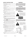
SAFETY INSTRUCTIONS
WARNING:
READ INSTRUCTIONS - All the safety and operating instructions should be
read before the appliances are operated.
RETAIN INSTRUCTIONS - The operating instructions should be retained for
future reference.
HEED WARNING - All warnings on the appliances and in the operating
instructions should be adhered to.
.
FOLLOW INSTRUCTIONS - All operating and use instructions should be
followed.
WATER AND MOISTURE - The appliances should not be used near water - for
example, near a bathtub, washbowl, kitchen sink, laundry tub, in a wet
basement, or near a swimming pool, etc.
LOCATION - The appliances should be installed in a stable location.
TO REDUCE THE RISK OF FIRE OR ELECTRICAL SHOCK, DO NOT EXPOSE THE APPLIANCES IN THIS SYSTEM TO RAIN OR MOISTURE. REPLACE FUSE ONLY AS MARKED.
CAUTION:
TO PREVENT ELECTRIC SHOCK, DO NOT
PLUG THE UNITS IN THIS SYSTEM INTO ANY
OUTLET OR EXTENSION CORD WITHOUT THE
STANDARD THREE-PRONG CONFIGURATION, WHERE THE CIRCULAR HOLE IS USED
FOR THE GROUND PLUG.
WALL OR CEILING MOUNT - The appliances should not be mounted to a wall
or ceiling.
IMPORTANT:
VENTILATION - The appliances should be situated so that their location or
position does not interfere with their proper ventilation. For example, the
appliances should not be situated on a bed, sofa, rug or similar surface
that may block the ventilation openings.
The lightning flash with the arrowhead,
within an equilateral triangle, is intended to alert the user of the presence of un-insulated "dangerous voltage" within the products' enclosures
that may be of sufficient magnitude to
constitute a risk of electrical shock to
persons.
HEAT - The appliances should be situated away from heat sources such as
radiators, heat registers, stoves, or other appliances that produce heat.
POWER SOURCES - The appliances should be connected to a power supply
only of the type described in the operating instructions or as marked on
the appliances.
GROUNDING - Make sure that the units in the system are always connected
to a standard three-prong grounded outlet (the circular pin is ground).
When operating this unit at a higher voltage with a different power cord
configuration, consult your dealer for the proper power cord/outlet combination to use before operating this unit.
POWER CORD PROTECTION - Power supply cords should be routed so that
they are not likely to be walked on or pinched by items placed upon or
against them, paying particular attention to cords at plugs, convenience
receptacles, and the points where they exit from the appliances.
CAUTION
RISK OF ELECTRIC SHOCK
DO NOT OPEN
CAUTION:
TO PREVENT RISK OF ELECTRICAL SHOCK, DO NOT
REMOVE COVER (OR BACK). NO USER-SERVICEABLE
PARTS ARE INSIDE ANY OF THE UNITS IN THIS SYSTEM.
REFER SERVICING TO QUALIFIED SERVICE PERSONNEL.
CLEANING - The appliances should be cleaned only with a polishing cloth or
a soft dry cloth. Never clean with furniture wax, benzine, insecticides or
other volatile liquids since they may corrode the face plates.
POWER LINES - An outdoor antenna should be located away from power lines.
PERIODS OF DISUSE - The power cord of the appliances should be unplugged
from the outlet when the units are not in use for a long period of time.
The exclamation point within the equilateral triangle is intended to alert the
user of the presence of important operating and maintenance (servicing)
instructions in the literature accompanying the appliances.
OBJECT AND LIQUID ENTRY - Care should be taken so that objects do not
fall and liquids are not spilled into the enclosures through openings.
DAMAGE REQUIRING SERVICE - The appliances should be serviced by an
authorized service center or qualified service personnel when:
• The power supply cords or plugs have been damaged; or
• Objects have fallen, or liquid has been spilled into the
appliances; or
• The appliances have been exposed to rain; or
• The appliances do not appear to operate normally or
exhibit a marked change in performance; or
• The appliances have been dropped; or the enclosures have
been damaged.
SERVICING - The user should not attempt to service the appliances beyond that
described in the operating instructions. For all other servicing, contact the
factory.
HTR-2400 Manual
Page 1
Introduction
Contents
HTR-2400 REAR PANEL CONNECTIONS ..................................... 4
TUNER CONNECTIONS ............................................................. 4
SOURCE CONNECTIONS (HOME & THEATER) .............................. 6
SOURCE CONNECTIONS (THEATER ONLY) .................................. 6
MULTI-ROOM SPEAKER & VIDEO OUTPUTS ............................... 8
THEATER SPEAKER, AUDIO & VIDEO OUTPUTS .......................... 8
IR LEARNER - CONNECTIONS & FEATURES .............................. 10
SOURCE AC CONNECTIONS ...................................................11
KEYPAD CONNECTIONS ..........................................................11
FRONT PANEL CONTROL .......................................................... 12
SELECTING ROOM SCREENS .................................................. 13
THEATER ZONE SCREEN ....................................................... 14
ALL ROOMS SCREEN ........................................................... 18
ROOM SCREEN (1-8) ........................................................... 20
PARTY GROUP SCREEN ........................................................ 23
ENTERING SETUP MODE .......................................................... 24
NAVIGATING SETUP MODE ..................................................... 25
MULTI-ROOM & GLOBAL SETUPS ............................................. 25
INPUT TRIM SETUP ............................................................... 26
PARTY MODE SETUP ............................................................ 26
ADA BUS SETUP ................................................................ 27
VOLUME SETUP ................................................................... 28
BALANCE SETUP ................................................................. 29
TONE SETUP ....................................................................... 30
LABELS & SOURCE SETUP ................................................... 32
SOURCE CONTROL SETUP .................................................... 33
AC POWER SETUP .............................................................. 34
Introduction
Page 2
HTR-2400 Manual
VERSION INFORMATION ............................................................
CLOCK SET ...........................................................................
FACTORY DEFAULT .................................................................
HOME & THEATER SETUP COMPARISONS ...................................
HOME THEATER SETUP ...........................................................
SPEAKER SIZE ....................................................................
SPEAKER DELAY .................................................................
SPEAKER LEVEL ..................................................................
BALANCE STORE .................................................................
BALANCE RECALL ...............................................................
VOLUME PRESETS ...............................................................
FINAL INPUT .......................................................................
SOURCE SETUP ...................................................................
TONE CONTROLS .................................................................
PRO LOGIC IIX ....................................................................
35
35
35
36
37
38
40
42
44
45
46
48
49
53
54
PC PROGRAM SETUP - PC CONNECTIONS .................................
PC PROGRAM SETUP - MULTI-ROOM ........................................
PC PROGRAM SETUP - HOME THEATER ....................................
PC PROGRAM SETUP - TUNERS ...............................................
PC PROGRAM SETUP - IR LEARNER .........................................
55
56
58
63
64
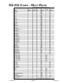
RS-232 CODES - MULTI-ROOM ...............................................
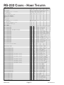
RS-232 CODES - HOME THEATER ...........................................
RS-232 CODES - XM TUNER .................................................
RS-232 CODES - FM/AM/WX TUNER ....................................
RS-232 CODES - IRL CODES .................................................
71
72
75
76
77
All specifications subject to change without prior notice.
©2005 Audio Design Associates, Inc. All rights reserved.
HTR-2400 Manual
Page 3
Introduction
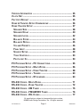
HTR-2400 REAR PANEL CONNECTIONS
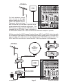
When installing the HTR-2400, you will need to connect audio and video sources for the
home and theater, digital sources and S-Video/Component video for the theater, antenna
connections for the tuners, AC and IR source connections, keypads, perhaps RS-232, speaker
lines for the house, speaker lines for the theater, perhaps line-level theater outputs, lowvoltage triggers for theater, and record analog, digital and S-Video outputs.
CAUTION
RISK OF ELECTRIC SHOCK
DO NOT OPEN
ATTENTION!
RISQUE DE CHOC ELECTRIQUE.
NE PAS OUVRIR
MADE IN U.S.A.
Switched AC
2.5 Amp Max
Per Outlet
+
-
Home
Theater
Amplified
Audio
Output
7.1 Channels
Room 1
(8 - 2 )
Room 2
(8 - 2 )
Room 3
(8 - 2 )
Room 4
(8 - 2 )
Room 5
(8 - 2 )
Room 6
(8 - 2 )
Room 7
(8 - 2 )
Front
Left
- R+
+L
-
- R+
+L -
- R+
+L -
- R+
+L -
- R+
+L -
- R+
+L -
- R+
+
+
Surround
Left
-
Center
+L -
Front Right
- R+
+
Surround Right
Room Keypad Control Connections • Use Any RJ-45 Port
+
Source 3
Source 5
Source 7
Room 8
Video
In
75
50
XM Radio®
L
R
Audio Output
(To Input)
AM/FM
Antenna
Input
AM/FM/WX Radio
L
R
Source 2
Normal
Mode
(PC Setup
& RS-232
Control)
Source 4
Source 6
AC
4
-
ADA Bus® Port
AC
3
+
Surround Back Right
RS-232 Port
Straight Through
Theater Trigger
12VDC Output
AC
2
Room 6
Room 4
Room 2
Y
XM
Antenna
Input
All Ouputs
8 -4
Do Not
Short
Outputs!
Do Not
Bridge
Outputs!
RX
RJ-45 Ports Are Not Room Specific • Cat. 5 Wire Is Straight-Through
Source 1
+
Surround Back
Left
Subwoofer
Gnd Out In +VDC
TX
-
Room 8
(8 - 2 )
+
+L -
-
Component Video Input 1
PB
PR
Y
1
2
3
4
Set RS-232 Switch
See IRL-5000
Component Video Input 3
PR
PB
Video
Out
Source 8
Room 7
Room 5
Room 3
Room 1 &
Theater
Y
PR
PB
Component Video Input 2
Y
1( -) 2 (+ )
1
3
1
2
4
2
PR
PB
Component Video Output
S-Video Inputs
AC
1
10ASB
115V
S-Video Out
5ASB
230V
RS-232
Switch
IR Learn
Mode
(IRL-5000)
IR Receiver (Learner)
IRL-5000
IR Emitter Outputs
120VAC~
60Hz
1200W
Source 8 Source 7 Source 6 Source 5 Source 4 Source 3 Source 2 Source 1
If Box Red
230VAC~
50Hz
1200W
Audio Output
(To Input)
CAUTION:
Disconnect Supply Cord Before Servicing.
ATTENTION:
Debrancher Avant Le Depannage.
To ensure that proper connections are maintained, wire management needs to be considered. It is recommended that wires and cables be fastened in such a way that as much of
their weight as possible be secured to something other than the actual connector or jack on
the HTR-2400. For pull out racks, make certain that there is enough room behind the rack to
permit the wires and cables to retract without pinching, pulling or crunching.
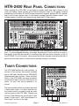
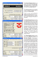
TUNER CONNECTIONS
The HTR-2400 features two tuner modules. At
the time of this printing, the modules available
are an XM Radio Module and an FM/AM/WX
(Weatherband) radio module. These modules,
like all of the HTR-2400’s rear-panel assembly,
are cards that slide in and out of the chassis on
tracks. As such, they can be updated or removed.
Room 1
(8 - 2 )
+L -
- R+
Room 2
(8 - 2 )
+L
-
Connections - Rear Panel
Page 4
- R+
+L -
- R+
Room 4
(8 - 2 )
+L -
- R+
Room 5
(8 - 2 )
+L -
Room 6
(8 - 2 )
- R+
TX
+L -
- R+
Room 7
(8 - 2 )
+L -
- R+
RX
Source 1
Source 3
Source 2
Source 4
Source 5
Source 7
Room
Source 8
Room
Video
In
75
50
The tuner modules feature an antenna input and
a stereo audio output. In order to hear the output of these tuners, you need to loop this audio
output to inputs on the HTR-2400. Typically, you
will loop Tuner Module one (far left side of rear
panel) to Audio Input 1 and Tuner Module 2 to
Audio Input 2 as show to the right.
Room 3
(8 - 2 )
XM
Antenna
Input
XM Radio®
L
R
Audio Output
(To Input)
AM/FM
Antenna
Input
AM/FM/WX Radio
L
R
Normal
Mode
(PC Setup
& RS-232
Control)
RS-232
Switch
IR Learn
Mode
(IRL-5000)
Source 6
IR Receiver (Lear
IR Emitter Outpu
Source 8 Source 7 Source 6 Source 5 Source 4
Audio Output
(To Input)
HTR-2400 Manual
FM Roof Antenna
(or other FM Antenna)
Room 1
(8 - 2 )
+L -
- R+
Room 2
(8 - 2 )
+L
-
Room 3
(8 - 2 )
- R+
+L -
Room 4
(8 - 2 )
- R+
+L -
- R+
Room 5
(8 - 2 )
+L -
Room 6
(8 - 2 )
- R+
TX
+L -
- R+
+L -
- R+
RX
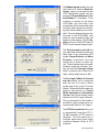
For basic antenna connections, one can run the radio
antenna directly into the HTR2400’s FM/AM/WX Module.
Please note, that in order to get
both FM and AM, you will need to provide the required antennas and combining components. The
XM Antenna, provided with the HTR-2400 can be
connected to the HTR-2400. Again, placement of
the XM antenna needs to be in such a manner that XM Radio reception is possible.
Source 1
Room 7
(8 - 2 )
Source 3
Source 5
Source 7
Room 8
Source 8
Room 7
Video
In
Source 2
75
50
AM/FM
Antenna
Input
XM
Antenna
Input
Normal
Mode
(PC Setup
& RS-232
Control)
AM/FM/WX Radio
L
R
XM Radio®
L
R
Source 4
RS-232
Switch
Source 6
IR Receiver (Learne
IR Learn
Mode
(IRL-5000)
IR Emitter Outputs
Source 8 Source 7 Source 6 Source 5 Source 4 S
Audio Output
(To Input)
Audio Output
(To Input)
ADA also provides the ACB Antenna Combiner Boxes (ACB-1 and ACB-2) which take both
the FM antenna, AM antenna, and XM antenna and combine these signals on a single RG-6
type coax cable. This cable can be run up to 200 feet to the HTR-2400’s equipment rack. The
ACB-1 and ACB-2 are sold as a set and the AML-1 AM Loop Antenna is sold separately.
FM Roof Antenna
(or other FM Antenna)
FM/WX
Ant. Input
Combined Ant.
Output to ACB-2
Power
LED
AML-1
AM Loop Antenna
(Hang AML-1 and
rotate for best
reception.)
AM
Ant. Input
ACB-1
XM Ant.
Input
ACB-2
From ACB-1 (200' RG6 Max!)
Power 12VDC To FM/AM To XM
Power
Tuner
Tuner
LED
Use Exactly 6' of RG6
For AM Loop Antenna Connection
ACB-1
FM/WX
Ant. Input
ACB-1
Combined Ant.
Output to ACB-2
Power
LED
AM
Ant. Input
XM Ant.
Input
Power
LED
+L -
ACB-2
ACB-2
12VDC
500mA
- R+
Room 3
(8 - 2 )
Room 2
(8 - 2 )
Room 1
(8 - 2 )
+L
-
- R+
+L -
- R+
+L -
- R+
+L -
Source 1
+L -
- R+
TX
Run Up To 200 Feet Of RG6
Between ACB-1 and ACB-2
Room 6
(8 - 2 )
Room 5
(8 - 2 )
Room 4
(8 - 2 )
- R+
RX
Source 3
Source 5
Sourc
From ACB-1 (200' RG6 Max!)
Power 12VDC To FM/AM To XM
Power
Tuner
Tuner
LED
Video
In
Power
LED
XM Radio®
L
R
HTR-2400 Manual
75
50
XM
Antenna
Input
Page 5
AM/FM
Antenna
Input
Source 2
Normal
Mode
(PC Setup
& RS-232
Control)
AM/FM/WX Radio
L
R
RS-232
Switch
Source 4
IR Learn
Mode
(IRL-5000)
Source 6
Sourc
IR Rece
IR Em
Source 8 Source 7 Source 6 Sou
Connections - Rear Panel
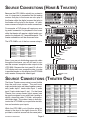
SOURCE CONNECTIONS (HOME & THEATER)
Because the HTR-2400 is actually two system in
one, it is important to remember that the analog
sources that play in the house can also play in
the theater while the digital sources that play in
the theater will not play in the house. As such,
some sources will require two audio connections.
+
-
Home
Theater
Amplified
Audio
Output
7.1 Channels
Room 4
(8 - 2 )
Room 5
(8 - 2 )
Room 6
(8 - 2 )
Room 7
(8 - 2 )
Front
Left
- R+
+L -
- R+
+L -
- R+
+L -
+
Surround
Left
Room 8
(8 - 2 )
+
+L -
-
- R+
+L -
Front Right
- R+
+
Surround Right
Room Keypad Control Connections • Use Any RJ-45 Port
ADA B
Gnd O
TX
RX
RJ-45 Ports Are Not Room Specific • Cat. 5 Wire Is Straight-Through
For example, a DVD player will require an analog audio connection for playback in the house
while the theater will require a digital audio connection for playback of 5.1 encoded material. The
theater connections will be discussed later.
Source 1
Source 3
Source 5
Source 7
Room 8
Room 6
Room 4
Room 2
Y
Video
In
Source 2
Normal
Mode
C Setup
RS-232
Control)
RS-232
Switch
Source 4
Component Video Input 1
PB
PR
Y
1
Component Vi
PB
Video
Out
Source 6
Source 8
Room 7
Room 5
IR Receiver (Learner)
IR Learn
Mode
(IRL-5000)
Room 3
Room 1 &
Theater
Y
PR
PB
Component Video Input 2
Y
PB
Component V
IRL-5000
IR Emitter Outputs
Source 8 Source 7 Source 6 Source 5 Source 4 Source 3 Source 2 Source 1
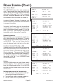
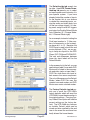
The HTR-2400’s out of the box source setup is:
SOURCE NAME/#
XM TUNER 1
FM TUNER 2
CD PLAYER 3
CD LIBRARY 4
SATELLITE 5
CABLE BOX 6
DVD PLAYER 7
AUXILIARY 8
AUDIO INPUT
ANALOG 1
ANALOG 2
ANALOG 3
ANALOG 4
ANALOG 5
ANALOG 6
ANALOG 7
ANALOG 8
VIDEO INPUT
OPEN
OPEN
OPEN
OPEN
VIDEO 5
VIDEO 6
VIDEO 7
VIDEO 8
AUXILIARY
DVD PLAYER
CABLE BOX
SATELLITE
CD LIBRARY
CD PLAYER
Even if you are not distributing composite video
throughout the house, you will still want to connect the sources’ composite video outputs to the
HTR-2400. Because the front panel 16 x 9 color
LCD display only runs composite video, in order
to preview images on this display, the HTR-2400
must receive a composite video signal.
SATELLITE
DVD PLAYER
Source 1
Source 3
Source 5
Source 7
Room 8
Room 6
Room 4
Room 2
Y
Video
In
Source 2
Source 4
Source 6
Component Video Input 1
PB
PR
Comp
Y
Video
Out
Source 8
Room 7
Room 5
Room 3
Room 1 &
Theater
Y
PB
PR
Component Video Input 2
Y
Comp
AUXILIARY or VCR
CABLE BOX
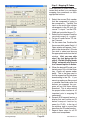
SOURCE CONNECTIONS (THEATER ONLY)
The Home Theater source setup is more flexible
than the multi-room system. The multi-room
audio and video jacks are linked together numerically (audio input 1 tracks video input 1, audio
input 2 tracks video input 2, etc.). For the Home
Theater, the source names (input names) can
be openly assigned to any audio jack (analog or
digital), composite video, S-Video, and component video input. This makes it easy to both customize the HTR-2400 to your particular installation and maximize your inputs.
While the HTR-2400’s out of the box setup (as
shown in the chart to the right) shows for 20 input labels, note that several use the same jacks.
Connections - Rear Panel
Page 6
INPUT NAME/#
XM TUNER 1
FM TUNER 2
CD PLAYER 3
CD LIBRARY 4
SATELLITE 5
CABLE BOX 6
DVD PLAYER 7
AUXILIARY 8
VCR 9
DVR/PVR 10
VIDEOGAME 11
CAMCORDER 12
COMPUTER 13
LASERDISC 14
LASRER AC3 15
PHONOGRAPH 16
SAT RECORD 17
TV RECORD 18
DVD RECORD 19
DVR RECORD 20
AUDIO
ANALOG 1
ANALOG 2
ANALOG 3
ANALOG 4
DIGITAL 1
DIGITAL 2
DIGITAL 3
ANALOG 8
ANALOG 8
DIGITAL 4
ANALOG 8
ANALOG 8
ANALOG 8
DIGITAL 5
DIGITAL 6
ANALOG 8
ANALOG 5
ANALOG 6
ANALOG 7
ANALOG 8
VIDEO
OFF
OFF
OFF
OFF
VIDEO 5
VIDEO 6
VIDEO 7
VIDEO 8
VIDEO 4
VIDEO 3
VIDEO 3
VIDEO 3
VIDEO 3
VIDEO 2
VIDEO 2
OFF
VIDEO 5
VIDEO 6
VIDEO 7
VIDEO 3
S-VIDEO
OFF
OFF
OFF
OFF
S1
S2
S3
S4
S4
OFF
OFF
OFF
OFF
OFF
OFF
OFF
S1
S2
S3
S4
COMPONENT
OFF
OFF
OFF
OFF
C1
C2
C3
OFF
OFF
OFF
OFF
OFF
OFF
OFF
OFF
OFF
C1
C2
C3
OFF
HTR-2400 Manual
Because you can limit the number of inputs displayed, rename the source names, reassign
jacks, this setup serves only as an example of
what can be done and corresponds to the HTR2400’s out of the box factory default setup.
SATELLITE
DVD PLAYER
LASER DISC PCM (Theater Only)
For digital audio sources, if coax type connections are available, ADA suggests using these
over TOS-Link connectors. When using TOSLink interconnects ADA suggests using the best
caliber cable available (frosted tip or convex tip).
TOS-Link cables have been known to reflect
against the TOS-Link receiver causing for audio
dropouts. Better cables help prevent this.
LASER DISC AC-3 (Theater Only)
DVR/PVR (Theater Only)
CABLE BOX
rner)
For DVD Audio discrete 5.1 playback, a six-channel analog bypass input is used on the HTR2400. Please note, that in order to access this
input, you will need to select a source name that
is not used, relabel it to read DVD AUDIO, and
assign the audio input to ANALOG BYPAS.
IRL-5000
uts
4 Source 3 Source 2 Source 1
6 CHANNEL DVD AUDIO INPUT
DVR/PVR (Theater Only)
Because the HTR-2400’s Home Theater has
open input assignment, it can use open (or unused) composite video inputs. In a common
setup, house inputs 1-4 are used by the tuners
and CD players and these devices typically do
not output any video. As such, the Home Theater can use these video inputs for theater specific sources like a DVR, VCR or Laser Disc
player.
Source 1
Source 3
Source 5
Source 7
Room 8
Room 6
Room 4
Room 2
Y
Video
In
Source 2
Source 4
Component Video Input 1
PB
PR
Comp
Y
Video
Out
Source 6
Source 8
Room 7
Room 5
Room 3
Y
Room 1 &
Theater
PB
PR
Component Video Input 2
Y
Comp
VCR (If Auxiliary is already used.)
LASER DISC (Theater Only)
SATELLITE
DVD PLAYER
The S-Video switcher of the HTR-2400 permits
four S-Video signals to be routed to two outputs.
Both outputs play the same signal. Please note
that an S-Video input only comes out of an SVideo output.
The component video switcher of the HTR-2400
permits three component video signals to be
routed to one component video output. The component video output only routes component video
inputs. If you wish to view composite or S-Video
sources on your display, you will need to connect both composite video, S-Video and component video from the HTR-2400 to your display
device.
HTR-2400 Manual
Page 7
Room 2
Component Video Input 1
PB
PR
Y
Room 1 &
Theater
Y
Y
PB
PR
Component Video Input 2
Y
Component Video Input 3
PR
PB
PB
PR
Component Video Output
1
3
1
2
4
2
S-Video Inputs
S-Video Out
AUXILIARY or VCR
CABLE BOX
SATELLITE
DVD PLAYER
m8
Room 6
Room 4
Room 2
Y
Component Video Input 1
PB
PR
Y
Component Video Input 3
PR
PB
Video
Out
m7
Room 5
Room 3
1
2
Room 1 &
Theater
Y
PR
PB
Component Video Input 2
Y
PR
PB
Component Video Output
3
4
S-Video Inputs
1
2
S-Video Out
CABLE BOX
Connections - Rear Panel
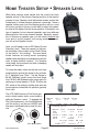
MULTI-ROOM SPEAKER & VIDEO OUTPUTS
The HTR-2400 provides class D (digital) power
amplification for the eight rooms in the house.
Each zone output is stable down to 2 Ohms but
best performance will be achieved when operating speaker loads in the 8-4 Ohm range. The
room amplifier channels are bridged. This means
that the ground (-) is unique to the left and right
channels. You cannot short the grounds together
because they are not common. Because of the
close proximity of all speaker outputs, pay close
attention to cleanly terminate speaker wires.
Each zone also has a composite video
output. These can be used to provide
video to local TVs or video capable
touch-screens.
Room 1
(8 - 2 )
+L -
Room 2
(8 - 2 )
- R+
+L
-
Room 3
(8 - 2 )
- R+
+L -
Room 4
(8 - 2 )
- R+
+L -
- R+
Room 5
(8 - 2 )
+L -
Room 6
(8 - 2 )
- R+
+L -
Room 7
(8 - 2 )
- R+
+L -
+L -
- R+
RM 1 RM 2 RM 3 RM 4 RM 5 RM 6 RM 7 RM 8
GROUND (-) FOR LEFT AND RIGHT
CHANNELS ARE INDEPENDENT.
DO NOT SHORT GROUNDS!
DO NOT SHORT SPEAKER!
DO NOT BRIDGE CHANNELS!
STABLE TO 2 OHMS!
ROOM 8
ROOM 4
ROOM 6
Source 1
- R+
Room 8
(8 - 2 )
Source 3
Source 5
ROOM 2
Source 7
Room 8
Room 6
Room 4
Room 2
Y
Video
In
Component Video Input 1
PB
PR
Y
Component Video Input 3
PR
PB
Video
Out
1
2
Room 1 shares its video output with
Home Theater zone. If any of the Home
ROOM 7
ROOM 1 / HOME THEATER
Theater sources have their composite
ROOM 5
ROOM 3
video active (set to ON), even if that
source is not selected, then as Room 1 selects a source, video will not follow. However if the
Home Theater is only being driven by S-Video or component video and all home theater
sources have composite video set to OFF, then when an input is selected for Room 1, the
video will follow. This feature permits you to determine if Room 1 is a video capable zone or
not. For a flexible Home Theater setup, ADA suggests assigning Room 1 to a zone that does
not have a video display.
Source 2
Source 4
Source 6
Source 8
Room 7
Room 5
Room 3
Y
Room 1 &
Theater
PB
PR
Component Video Input 2
Y
PB
PR
Component Video Output
S-Vide
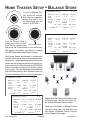
THEATER SPEAKER, AUDIO & VIDEO OUTPUTS
SURROUND LEFT
CENTER
The HTR-2400 features a Class A/B high- FRONT LEFT
SURROUND BACK LEFT
current power amplifier for the Home Theater zone. This amplifier is stable to 4 Ohms.
Do not attempt to bridge this amplifier. If
you are using active subwoofers and/or are
not using back surround speakers, you can
leave these speaker channels unused.
Make certain that your speaker connections FRONT RIGHT
SURROUND BACK RIGHT
are clean and secure.
SURROUND RIGHT
SUBWOOFER
DO NOT SHORT SPEAKERS & BRIDGE CHANNELS!
High Power
STABLE TO 4 or 2 OHMS BASED ON SIDE PANEL
8 To 4 Ohms
AMPLIFIER IMPEDANCE SWITCH POSITION.
+
Home
Theater
Amplified
Audio
Output
7.1 Channels
-
Front
Left
+
HTR-2400
Chassis
Left Side
Standard Power
4 To 2 Ohms
Connections - Rear Panel
HTR-2400
Theater Amp
Impedance
Switch
+
+
Surround
Left
-
Front Right
-
+
Surround Right
-
Center
+
+
Surround Back
Left
-
Subwoofer
-
All Ouputs
8 -4
Do Not
Short
Outputs!
Do Not
Bridge
Outputs!
+
Surround Back Right
The HTR-2400 features a Theater Amplifier Impedance Switch
located on the left side of the chassis. In the up position, you
will get more power but the amplifier is only stable to 4 Ohms.
In the down position, the amplifier is stable to 2 Ohms.
Page 8
HTR-2400 Manual
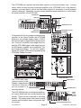
The HTR-2400 also features line-level audio outputs for the home theater zone. In many
cases, while you may be using the power amplifier in the HTR-2400 for all of the theater’s
speakers, you may need to use its line-level audio outputs for connection to a self-powered
(active) subwoofer. Alternately, you can connect additional power amplifiers or a multi-channel power amplifier to the HTR-2400.
SURROUND LEFT
FRONT LEFT
Normal
Mode
(PC Setup
& RS-232
Control)
RS-232
Switch
IR Receiver (Learner)
IR Learn
Mode
(IRL-5000)
CENTER
IRL-5000
IR Emitter Outputs
Source 8 Source 7 Source 6 Source 5 Source 4 Source 3 Source 2 Source 1
SURROUND BACK LEFT
FRONT RIGHT
SURROUND BACK RIGHT
SURROUND RIGHT
SUBWOOFER
ofer
In the event that you are using an external power
amplifier in the Home Theater, the HTR-2400
features a low-voltage trigger output (12VDC)
that can be used to trigger an ADA power amplifier. Using a 2-conductor low-voltage wire, connect the HTR-2400 trigger to the trigger input on
the ADA power amplifier (set the amplifier Trigger Switch accordingly). You will also need to
set the DC Trigger to ON when programming the
HTR-2400 Theater Sources.
ort
DC
Surround Back Right
RS-232 Port
Straight Through
Theater Trigger
12VDC Output
AC
2
Set RS-232 Switch
See IRL-5000
4
3
ut
1( -) 2 (+ )
1
3
1
2
4
2
S-Video Inputs
AC
1
10ASB
115V
S-Video Out
5ASB
230V
120VAC~
60Hz
1200W
If Box Red
230VAC~
50Hz
1200W
CAUTION:
Disconnect Supply Cord Before Servicing.
ATTENTION:
Debrancher Avant Le Depannage.
CAUTION
RISK OF ELECTRIC SHOCK
DO NOT OPEN
ATTENTION!
RISQUE DE CHOC ELECTRIQUE.
NE PAS OUVRIR
MADE IN U.S.A.
Switched AC
2.5 Amp Max
Per Outlet
+
-
Home
Theater
Amplified
Audio
Output
7.1 Channels
Room 1
(8 - 2 )
Room 2
(8 - 2 )
Room 3
(8 - 2 )
Room 4
(8 - 2 )
Room 5
(8 - 2 )
Room 6
(8 - 2 )
Room 7
(8 - 2 )
Front
Left
- R+
+L
-
- R+
+L -
- R+
+L -
- R+
+L -
- R+
+L -
- R+
+L -
+
+
-
Surround
Left
Center
- R+
+L -
+
Surround Right
+
-
Source 1
Source 3
Source 2
Source 4
Source 5
Source 7
Room 8
Room 6
Source 8
Room 7
Room 5
Room 4
Room 2
Y
AM/FM
Antenna
Input
ADA Bus® Port
Component Video Input 1
PB
PR
Y
1
2
3
RS-232 Port
Straight Through
Theater Trigger
Component Video Input 3
PR
PB
Video
Out
Source 6
1
2
Room 3
Y
Room 1 &
Theater
Y
PR
PB
Component Video Input 2
PB
PR
Component Video Output
1( -) 2 (+ )
3
1
4
S-Video Out
IR Receiver (Learner)
IR Learn
Mode
(IRL-5000)
115V
10ASB
115V
115 V
IRL-5000
MAIN FUSE
115V~ 10 ASB
230V~ 5 ASB
IR Emitter Outputs
120VAC~
60Hz
1200W
Source 8 Source 7 Source 6 Source 5 Source 4 Source 3 Source 2 Source 1
230V
If Box Red
6Ω
230VAC~
50Hz
1200W
Audio Output
(To Input)
Audio Output
(To Input)
230V~
1/10 ASB
AC
1
2
S-Video Inputs
-
Bypass Trigger
CAUTION:
Disconnect Supply Cord Before Servicing.
ATTENTION:
Debrancher Avant Le Depannage.
All-On Trigger
1 2
PTM-8150
-
+
ATTENTION!
1200
WATTS
MAX
CH
1
INPUT
47KΩ
OUTPUT 2-16 Ω
-
+
CH
2
INPUT
47K
OUTPUT 2-16Ω
-
+
CH
3
INPUT
47K
OUTPUT 2-16 Ω
-
+
CH
4
STBY FUSE
115V~
2/10 ASB
INPUT
47KΩ
230V~
1/10 ASB
OUTPUT 2-16Ω
CH
5
+
-
INPUT
47KΩ
OUTPUT 2-16Ω
CH
6
+
-
INPUT
47KΩ
INPUT
47KΩ
OUTPUT 2-16Ω
CH
7
+
-
115 V
MAIN FUSE
115V~ 10 ASB
230V~ 5 ASB
OUTPUT 2-16Ω
CH
8
115V
115V
230V
INPUT
47KΩ
115 V
RISK OF ELECTRIC SHOCK
DO NOT OPEN
RISQUE DE CHOC ELECTRIQUE.
NE PAS OUVRIR
MADE IN U.S.A.
OUTPUT 2-16Ω
230V
All Channels
12VDC
1(-) 2(+)
CAUTION
Typical Power:
250-600 Watts
Ultimate Max. Power:
1200 Watts
Average Thermal Load: 2048 BTU/Hr
8 Channel Power Amplifer
1200
WATTS
MAX
STBY FUSE
115V~
2/10 ASB
12VDC Output
Set RS-232 Switch
See IRL-5000
4
5ASB
230V
Normal
RS-232
Mode
Switch
(PC Setup
& RS-232
Control)
AM/FM/WX Radio
L
R
XM Radio®
L
R
CAUTION
RISK OF ELECTRIC SHOCK
DO NOT OPEN
RISQUE DE CHOC ELECTRIQUE.
NE PAS OUVRIR
MADE IN U.S.A.
AC
2
Video
In
XM
Antenna
Input
AC
4
AC
3
+
Surround Back Right
Subwoofer
Gnd Out In +VDC
75
Surround Back
Left
All Ouputs
8 -4
Do Not
Short
Outputs!
Do Not
Bridge
Outputs!
RX
RJ-45 Ports Are Not Room Specific • Cat. 5 Wire Is Straight-Through
50
+
ATTENTION!
Front Right
- R+
Room Keypad Control Connections • Use Any RJ-45 Port
TX
-
Room 8
(8 - 2 )
+
+L -
-
+
-
Bypass Trigger
All-On Trigger
1 2
All Channels
12VDC
1(-) 2(+)
230V
115 V
Warning! Do Not Short Outputs
WARNING! Risk Of Hazardous Energy!
Make Proper Connections.
AVERTISSEMENT! Energie Electrique Dangereuse! Faire Des Connexions
Propres Pour L'Hautparleur. Voir La Notice De Fonctionnement.
The HTR-2400 video
outputs connect to the
Theater’s video display.
The extra S-Video output can connect to a
recording device.
115V
CAUTION: Disconnect Supply Cord Before Servicing.
ATTENTION: Debrancher Avant Le Depannage.
2 CONDUCTOR
LOW VOLTAGE WIRE
HOME THEATER
2 CONDUCTOR
LOW VOLTAGE WIRE
e1
Source 3
Source 5
Source 7
Room 8
Room 6
Room 4
Room 2
Y
Video
In
e2
Source 4
Source 6
Component Video Input 1
PB
PR
Y
Component Video Input 3
PR
PB
Video
Out
Source 8
Room 7
Room 5
Room 3
Room 1 &
Theater
Y
PB
PR
Component Video Input 2
HOME THEATER/ROOM 1
Y
PB
PR
Component Video Output
1
3
1
2
4
2
S-Video Inputs
S-Video Out
RECORDING DEVICE
HOME THEATER
The HTR-2400 features an analog and digital audio output which track the source playing in the
theater. These can be connected to recording
devices. The analog output only passes analog
sources and the digital output only passes digital sources.
HTR-2400 Manual
Page 9
DIGITAL
AUDIO
RECORD
OUTPUT
ANALOG AUDIO RECORD OUTPUT
Connections - Rear Panel
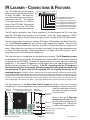
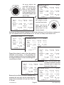
IR LEARNER - CONNECTIONS & FEATURES
The HTR-2400 features an internal
eight source IR Learner that is based
on ADA’s IRL-5000. The latter section of this manual discusses the programming of the IRL. The diagram
to the right shows the out of the box
setup of the HTR-2400. Ports can be
reassigned during the HTR-2400
setup to suit your custom installation.
Normal
Mode
(PC Setup
& RS-232
Control)
RS-232
Switch
IR Learn
Mode
(IRL-5000)
IR Receiver (Learner)
IRL-5000
IR Emitter Outputs
Source 8 Source 7 Source 6 Source 5 Source 4 Source 3 Source 2 Source 1
Port 1 - DVR/PVR (Theater Input Label 10)
Port 2 - VCR (Theater Input Label 9)
Port 3 - CD Player (Home & Theater Input 3)
Port 4 - CD Library (Home & Theater Input 4)
Port 5 - Satellite (Home & Theater Input 5)
Port 6 - Cable Box (Home & Theater Input 6)
Port 7 - DVD Player (Home & Theater Input 7)
Port 8 - Auxiliary (Home & Theater Input 8)
To IR Flashers
The IRL can be removed to alter IR port operation or to even program the IRL in the shop
while the HTR-2400 chassis begins to be installed. To do this, simply connect a 12VDC
500mA power supply to the IRL board to program the IRL outside of the HTR-2400 chassis.
There are three types of jumper pin settings; IR Flasher, IR Repeating, and Serial Data Control. The IR Flasher jumper pins are a group of eight jumper pins together. The out of the
box setup has these jumper pins offset (un-shunted) so the pins are there but simply not in
place. When these pins are offset (not in place, un-shunted), the port they reference are set
to use an IR flasher (emitter). When the jumper pin is in place (shunted), the port is set for
serial data control with the IR carrier stripped out.
The other two types of jumper pins are grouped by port number. The IR Repeating jumper
pin determines if the port will pass IR that comes down the ADA Bus from IR receivers located
in keypads (or the IRR-5000). To defeat IR repeating entirely for a port, remove or offset the
jumper pin. If you require IR repeating, set the jumper pin to the appropriate position (IR
flasher or serial connection {no IR carrier}). If the IRL is working from the PC program’s
Simulator but not from the keypads, and the keypads have been programmed to track
the appropriate IRL ports, then turn IR repeating OFF by offsetting (removing) the IR
repeating jumpers. REASON - When a keypad issues a transport command, the RS-232 code for the IRL
is sent down the ADA Bus to the IRL so that it can then issue the source’s IR command. If repeating is on, the
keypad’s command first emits through the IR flasher. If the source component’s IR receiver is slow to cool down
(so that it can take the next IR command), when the IRL releases the actual command (a moment later), the
source component’s IR receiver may reject it. By turning off IR repeating, only the IRL source function is sent.
The last jumper pin is the Serial Data Control jumper pin which is only used if you are
connecting to a source component’s rear panel serial data connection. Here you can opt to
send the serial data in the norIR Receiver
IR Flasher (Not Shunted - Jumper Pin Out)
IR Repeating
(Capture)
Serial Data (Shunted - Jumper Pin In)
Frequency Trim Pot
mal (Norm) position or inverted
(Invert) position.
12VDC 500mA
External DC
ADA Bus Jack
RS-232 Jack
There is also an IR Repeater
Frequency trim pot that adjusts the IR carrier frequency for
IR repeating only. This pot has
no effect with keypad control.
IR Repeating - Remove to Defeat IR Repeating
(IR {Default} or Serial)
Serial Data Control
(Normal or Inverted)
Connections - Rear Panel
Page 10
HTR-2400 Manual
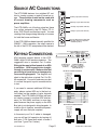
SOURCE AC CONNECTIONS
CAUTION
RISK OF ELECTRIC SHOCK
DO NOT OPEN
The HTR-2400 features four switched AC outlets for turning sources on and off based on usage. These outlets should not be used with
hi-current drawing components such as
power amplifiers.
The HTR-2400’s out of the box setup has these
four outlets assigned to the CD Player, CD Library, DVD Player and Auxiliary inputs. You can
reassign their usage during the setup of sources
for both the home and theater.
ATTENTION!
RISQUE DE CHOC ELECTRIQUE.
NE PAS OUVRIR
MADE IN U.S.A.
Switched AC
2.5 Amp Max
Per Outlet
AC
4
Auxiliary - Input 8 (Home & Theater)
AC
3
DVD Player - Input 7 (Home & Theater)
AC
2
CD Library - Input 4 (Home & Theater)
AC
1
CD Player - Input 3 (Home & Theater)
10ASB
115V
5ASB
230V
120VAC~
60Hz
1200W
AC Power Outlet (At least 10A @ 115V)
(Unit will be marked if configured for
230V/50Hz operation.)
If Box Red
If the HTR-2400 has been internally modified for
230VAC - 50Hz operation, the small square to
the left of the EIC AC receptacle will be marked.
KEYPAD CONNECTIONS
230VAC~
50Hz
1200W
CAUTION:
Disconnect Supply Cord Before Servicing.
ATTENTION:
Debrancher Avant Le Depannage.
The rear panel ADA Bus port will not power
additional ADA Bus keyapds!
Room Keypad Control Connections • Use Any RJ-45 Port
Gnd Out In +VDC
RJ-45 Ports Are Not Room Specific • Cat. 5 Wire Is Straight-Through
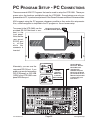
ADA keypads connect directly to the HTR2400’s eight RJ-45 female connectors. The
suggested wire is standard Cat. 5 cable.
Wiring is the most critical aspect of an ADA
installation. ADA keypads wire straightthrough (no crisscross). Make certain that
your wiring is free of error or damage prior
to connecting keypads! The diagram and
chart to the right show a typical Cat. 5 to RJ45 connection. Your color code may vary but
it is critical that point to point connections be
in tact.
If you need to connect additional ADA keypads, please contact ADA as to the best result based on the number of extra keypads
needed. The HTR-2400’s ADA Bus jack cannot simply connect to another ADA wire harness (i.e. WH-2000) and then to more keypads because the power supply on the ADA
Bus jack is not designed to drive keypads. In
order for this to function, an additional powersupply will most likely be required.
In the event your Cat. 5 cable is damaged,
you can still get full operation by leaving off
both pins 1 & 8 (leave both wires off even if
you have 7 good Cat. 5 wires).
HTR-2400 Manual
Page 11
ADA Bus® Port
1
2
3
4
RS-232 Port
Straight Through
Theater Trigger
Set RS-232 Switch
See IRL-5000
12VDC Output
1( -) 2 (+ )
To RS-232
Control System
To ADA Keypads
To Additional ADA Bus
(Position Does
Devices or Components
Not Matter)
(iHome Multi-Center, MSC-1,
ISO-E, ISO-USB, etc.)
RJ-45 Cat. 5 Cable Connector
B
L
U
E
B
L
U
E
G
R
E
E
N
W
H
I
T
E
O
R
A
N
G
E
O
R
A
N
G
E
W
H
I
T
E
G
R
E
E
N
B
R
O
W
N
W
H
I
T
E
W
H
I
T
E
B
R
O
W
N
8 7 6 5 4 3 2 1
Front
PIN NUMBER
PIN 1
PIN 2
PIN 3
PIN 4
PIN 5
PIN 6
PIN 7
PIN 8
Top
COLOR
FUNCTION
+20V
GND
TXRX+
RXTX+
+20V
GND
BROWN
BROWN/WHITE
GREEN/WHITE
ORANGE
ORANGE/WHITE
GREEN
BLUE
BLUE/WHITE
RJ-45 Cat. 5 Cable Connector
B
L
U
E
G
R
E
E
N
O
R
A
N
G
E
W
H
I
T
E
O
R
A
N
G
E
G
R
E
E
N
B
R
O
W
N
W
H
I
T
E
W
H
I
T
E
8 7 6 5 4 3 2 1
Front
Top
Connections - Rear Panel
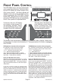
FRONT PANEL CONTROL
The HTR-2400’s easy to use front panel permits
you to control the entire home. The buttons flanking the LCD display are source transport functions (source control). How these operate will
depend on how your custom installation professional programmed the HTR-2400’s infrared
learner (IRL). Because the two tuners are internal to the HTR-2400 and are not controlled by
the IRL, their operation is explained below.
There are LCD adjustment buttons above the display.
+
-
SELECT
MENU
OFF
The right side of the display features additional source transport
buttons including play, stop,
pause, reverse play, forward, rewind and navigation buttons.
To the left of the color LCD display
are numeric source transport buttons including * and Enter. There is
also the black Master Power switch
located to the far left of the bezel.
The Master Power switch needs to be pushed in for the HTR-2400 to operate. When servicing the system, it is wise to turn this button off. Turning the button off is similar to unplugging
the HTR-2400.
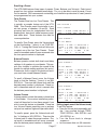
XM Radio Tuner Operation (Also on keypads)
0-9 & ENTER - Access XM channel numbers.
* - Updates the current channel & song info.
<< & >> - Advances channels down & up.
< & > - Advances through XM genres.
|| & [] - Advances through channels in a genre.
MAIN - Advances through presets (preset skip up).
Up & Down - Preset skips up and down.
Storing An XM Station As A Preset
When on a station that you wish to store as a preset,
press 0 twice and then press ENTER. You will be
prompted to “STORE? PR #”. If this preset number is
right, press ENTER to store this as one of the 30 possible presets.
If you wish to store this station on a different preset
number, use < or > to cycle through other presets and
then press ENTER when you are ready to store the
station as a preset. A * appearing next to the preset
number indicates that the preset is already being used.
If you press ENTER while on a preset number with a *
next to it, then the new station will override the previous one.
Operation Instructions
FM/AM/WX Tuner Operation (Also on keypads)
0-9, * & ENTER - Access presets (1-30) or direct tunes
stations by frequency (1027 or 102*7 enters 102.7).
<< & >> - Tunes down & up.
< & > - Seeks down & up.
[] - Switches between stereo & mono modes (FM only).
|| - Switches between radio bands (FM>WX>AM>FM).
MAIN - Advances through presets (preset skip).
Up & Down - Preset skips up and down.
Storing An XM Station As A Preset
When on a station that you wish to store as a preset,
press 0 twice and then press ENTER. You will be
prompted to “STORE? PR #”. If this preset number is
right, press ENTER. If you wish to store this station
on a different preset number, use < or > to cycle through
other presets and then press ENTER. A * appearing
next to the preset number indicates that the preset is
already being used. If you press ENTER while on a
preset number with a * next to it, then the new station
will override the previous one. You will then have the
option to label (4 characters) the station (i.e. NEWS,
ROCK, WABC, etc). To skip this just hit ENTER again.
Or use the < & > buttons to change characters along
with the << & >> buttons to move the flashing character position. When done hit ENTER.
Page 12
HTR-2400 Manual
SELECTING ROOM SCREENS
elect Sc
To S
ree
rn
n
u
T
R OOM
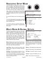
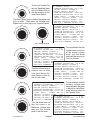
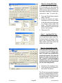
The Theater Zone screen details the activity of
the HTR-2400 digital home theater preamplifier.
Turning the Source knob will scroll through inputs and pressing the Source knob will engage
the selection. The Mode knob works in the same
manner and the Volume knob raises or lowers
the Theater’s volume. The other features can
be accessed by pressing the Volume knob. A
flashing * (cursor) will appear next to the first feature and turning the Volume knob will adjust that
feature. To exit this setup, press the Volume knob
repeatedly, wait 30 seconds for the feature to time
out, or turn the Room knob. Pressing the Off
button will turn off the Theater Zone.
The All Rooms screen details the status of all
nine rooms including the Theater Zone. Here,
pressing the Room knob will advance the * (cursor) through all rooms. Turning the Source knob
will cycle through inputs and pressing the Source
knob will engage the selected source.
For each zone there is an individual Room
screen showing that room’s status. Turning the
Source knob will scroll through inputs and pressing the Source knob will engage the selection.
Turning the Volume knob will adjust volume. Just
like the Theater Zone, pressing and then turning
of the Volume knob allows you to adjust the other
features. To turn off a room, press the Off button. To turn off all rooms (not including the Theater), press and hold the Off button.
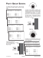
The Party Group screen lets you turn on several
rooms to the same source. Please note, making
rooms track one or more of the four Party Groups
is a feature that your installer must setup. A * will
appear next to rooms assigned to the Party group.
Pressing the Room knob advances through the
four Party Groups. Turning and then pressing
the Source knob, engages the selected input.
HTR-2400 Manual
Page 13
The HTR-2400 features eleven screens
which can be cycled through by turning
the Room knob.
THEATER ZONE
VOL -41.5 DB
DVD PLAYER 7
PLIIx MOVIE
BASS
TREB
IN
OUT
+ 2.5DB
+ 3.0DB
2.0.0.0
3.2.1.2
JAN
1
*THEATER ZONE
ROOM 1
ROOM 2
ROOM 3
ROOM 4
ROOM 5
ROOM 6
ROOM 7
ROOM 8
JAN
1
95.5
+ 6
+ 4
+ 7
1
1
1
2
3
4
JAN
FM
BALANCE EQUAL
LOUDNESS ON
LIMITER
ON
PARTYGROUP 1
*ROOM
*ROOM
*ROOM
ROOM
OFF
OFF
OFF
OFF
OFF
OFF
OFF
OFF
AM
VOLUME 36
TUNER 2
JAN
THEATER OFF
ROOM
ROOM
ROOM
ROOM
ROOM
ROOM
ROOM
ROOM
12:01
ROOM 1
BASS
MID
TREB
TONE
TONE RECALL 1
BAL
RECALL 1
VOL
RECALL 1
D NRM
0 DB
12:01 AM
12:01 AM
XM TUNER 1
ROOM
ROOM
*ROOM
ROOM
1
5
6
7
8
12:01 AM
Operation Instructions
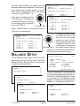
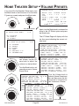
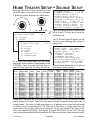
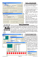
THEATER ZONE SCREEN
To access the Theater Zone page, turn the Room
knob until the display to the right appears. Once
on the Theater Zone page, you can see the status of the theater as well as adjust the following:
1
Select a Source (input).
2
Change Modes.
3
Adjust Volume.
4
Turn the Theater off.
5
Raise or lower Bass levels.
6
Raise or lower Treble levels.
7
Recall a Tone Preset.
8
Recall a Balance Preset.
9
Recall a Volume Preset.
THEATER ZONE
DVD PLAYER 7
PLIIx MOVIE
BASS
TREB
IN
OUT
+ 2.5DB
+ 3.0DB
2.0.0.0
3.2.1.2
JAN
1
Selecting A Source (Turning Theater On)
If the Theater is off, selecting an input will turn it THEATER ZONE
on. To select an input, turn the Source knob. A
DVD PLAYER 7
The HTR-2400 permits
Select Sou
o
rc
you scroll through the
nT
e
PLIIx MOVIE
ur
RC E
U
O
S
source components
BASS + 2.5DB
ZONE
connected to your sys- THEATER
TREB + 3.0DB
A
tem without immediIN
2.0.0.07
DVD PLAYER
ately switching away
OUT
3.2.1.2
1
PLIIxJAN
MOVIE
from what you are already using.
The
THEATER
ZONE
BASS + 2.5DB
source names that you could select appear in
TREB
+
3.0DB
A
DVD PLAYER
IN
2.0.0.07
the area marked “B” while the current status of
OUT
3.2.1.2
the room is shown in the area marked as “A”.
PLIIx
MOVIE
JAN
1
TONE RECALL 1
BAL
RECALL 1
VOL
RECALL 1
D NRM
0 DB
12:01 AM
VOL -41.5 DB
B
XM TUNER 1
s
T
VOL -41.5 DB
To engage the selected source (displayed in area
“B”), press the Source knob. The HTR-2400 will
switch inputs and the Front Plate
new source name appears in area “A”.
BASS
TREB
IN
OUT
+ 2.5DB
+ 3.0DB
2.0.0.0
3.2.1.2
JAN
1
TONE
RECALLDB1
VOL -41.5
BAL
RECALL 1
B
VOL
RECALL
FM TUNER
2 1
D NRM
0 DB
12:01 AM
VOL -41.5
TONE
RECALLDB
1
BAL
RECALL 1
B
CD PLAYER
VOL
RECALL3 1
D NRM
0 DB
12:01 AM
TONE RECALL 1
BAL
RECALL 1
VOL
RECALL 1
D NRM
0 DB
12:01 AM
Press Knob
To Engage
THEATER ZONE
The Selected
Source Device
VOL -41.5 DB
CD PLAYER 3
QUAD BYPASS
Side View
Chassis Side
Note that your source names may differ from what
is shown here. Also, the number following the
source name refers to the order of the inputs and
not the number of say CD players in the system.
Operation Instructions
Page 14
BASS
TREB
IN
OUT
+ 2.5DB
+ 3.0DB
2.0.0.0
3.2.1.2
JAN
1
TONE RECALL 1
BAL
RECALL 1
VOL
RECALL 1
D NRM
0 DB
12:01 AM
HTR-2400 Manual
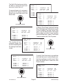
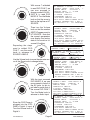
Selecting Modes
The HTR-2400 features over 50 modes for film,
TV, and music. Your installer may have also
setup Default modes for you, which engage automatically when a source is selected. If you wish
to select a different mode, turn the Mode knob.
THEATER ZONE
VOL -41.5 DB
DVD PLAYER 7
PLIIx MOVIE
BASS + 2.5DB
TONE RECALL 1
THEATER
ZONEBAL VOL
-41.51 DB
TREB
+ 3.0DB
RECALL
IN
2.0.0.0
VOL
RECALL 1
PLAYER D
7 NRM
OUT DVD
3.2.1.2
0 DB
C JAN 1
D
12:01 AM
PLIIx MOVIE
PLIIx MUSIC
BASS + 2.5DB
TONE RECALL 1
TREB + 3.0DB
BAL
RECALL 1
ZONE
-41.5
IN THEATER
2.0.0.0
VOL VOL
RECALL
1 DB
OUT
3.2.1.2
D NRM
0 DB
DVD
7
JANPLAYER
1
12:01
AM
To Select Mo
de
rn
u
T
MODE
Just like source selection, the HTR-2400
permits you scroll through the available
modes without actually making the change
until the desired mode is displayed in area
“D”. The current mode will remain on the
display in area “C” until the switch is enacted. To change the mode, press the
Mode knob.
Front Plate
Press Knob
To Engage Mode
PLIIx MUSIC
BASS
TREB
IN
OUT
+ 2.5DB
+ 3.0DB
2.0.0.0
3.2.1.2
JAN
1
TONE RECALL 1
BAL
RECALL 1
VOL
RECALL 1
D NRM
0 DB
12:01 AM
Side View
Chassis Side
o Adjust Volu
nT
m
ur
LUM
VO
E
e
Adjusting Volume
The volume in the Theater Zone can be raised
or lowered using the Volume knob.
T
Note, because the HTR-2400’s DSP (digital signal processor - the home theater’s brain) is
“auto-sensing”, it will only display modes that can be used. For example, when playing back
a 5.1 channel encoded DVD, only “Cinema Modes” will appear as you turn the Mode knob.
When playing back a normal CD in the DVD player, only “2 Channel” modes will appear.
Muting Volume
To mute the volume in the Theater Zone, press
the Off button. To unmute, press the Off button
again or give the Volume knob a slight turn.
Turning the Theater Zone Off
Press and hold the Off button to turn the Theater
Zone off. Please note, that this will not perform
an All Off function for the other eight rooms on
the system. The Theater Zone operates independently from the rest of the home with respect
to all off.
HTR-2400 Manual
Page 15
Operation Instructions
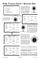
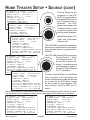
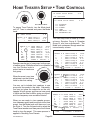
THEATER ZONE SCREEN (cont.)
To access the Theater Zone’s other features including:
Raise or lower Bass levels.
Raise or lower Treble levels.
Recall a Tone Preset.
Recall a Balance Preset.
Recall a Volume Preset.
Front Plate
Press Knob
To Advance
To The Next
Feature
press the Volume knob.
A * (cursor) will begin flashing on the first feature, BASS.
THEATER ZONE
Side View
PLIIx MOVIE
TONE RECALL 1
BAL
RECALL 1
VOL
RECALL 1
D NRM
0 DB
VOL -41.5
DB
12:01 AM
DVD PLAYER 7
PLIIx MOVIE
*BASS + 3.5DB
TONE RECALL 1
TREB + 3.0DB
BAL
RECALL 1
IN
2.0.0.0
VOL
RECALL 1
OUT
3.2.1.2
D NRM
0 DB
THEATER ZONE
VOL -41.5 DB
JAN
1
12:01 AM
DVD PLAYER 7
PLIIx MOVIE
*BASS
TREB
IN
OUT
+ 4.0DB
+ 3.0DB
2.0.0.0
3.2.1.2
JAN
1
THEATER ZONE
TONE RECALL 1
BAL
RECALL 1
VOL
RECALL 1
D NRM
0 DB
12:01 AM
VOL -41.5 DB
PLIIx MOVIE
+ 4.0DB
+ 3.0DB
2.0.0.0
3.2.1.2
JAN
1
Operation Instructions
The HTR-2400’s out of the box settings
have all speakers not including the
subwoofer operate with these bass and
treble control options. However, your custom installer may have modified your systems operation such that these features
do operate in this manner. ADA recommends consulting with your custom install
professional to determine if these features
should be used.
Bass Adjustment
While the * (cursor) is on BASS, turning
the Volume knob will raise or lower the
bass level.
To advance to the next feature, press the
Volume knob.
DVD PLAYER 7
BASS
*TREB
IN
OUT
o Adjust Volu
nT
m
ur
UM
VOL E
e
T
DVD PLAYER 7
*BASS + 3.0DB
TREB + 3.0DB
IN
2.0.0.0
OUT
3.2.1.2
THEATER ZONE
JAN
1
Chassis Side
VOL -41.5 DB
TONE RECALL 1
BAL
RECALL 1
VOL
RECALL 1
D NRM
0 DB
12:01 AM
Page 16
Treble Adjustment
While the * (cursor) is on TREB, turning
the Volume knob will raise or lower the
treble level.
To advance to the next feature, press the
Volume knob.
HTR-2400 Manual
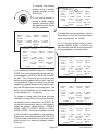
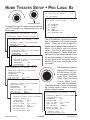
Recalling a Preset
The HTR-2400 features three types of presets (Tones, Balance, and Volume). Each type of
preset has four options numbered accordingly. For you to be able to recall a preset, it must
first be created. ADA recommends contacting your installation professional to see if presets
are programmed into your system.
Tone Presets
The Theater Zone has four Tone Presets. This
is actually a complex feature set of the HTR2400. Tone Presets permit the installer to create two groups of speakers (A and B). Each
grouping can have an independent bass frequency point, bass level, treble frequency point,
and treble level. These features are used for
room equalization.
THEATER ZONE
To recall a Tone Preset, press the Volume knob
so that the flashing * (cursor) is on TONE RECALL #. Turning the Volume knob will allow you
to select one of the four Tone Presets. Preset
recall is immediate and will occur a second after
the tone preset number is displayed.
Balance Presets
Balance presets contain both levels and delay
settings of all speakers in your theater. This permits your installer to optimize the sound in the
theater for multiple seating positions (hot spots).
Please note, that in order for this feature to work,
you must have stored Balance Presets.
To recall a Balance Preset, press the Volume
knob so that the flashing * (cursor) is on BAL
RECALL #. Then turn the Volume knob until the
desired preset number is displayed. Preset recall is immediate and will occur a second after
the balance preset number is displayed.
Volume Presets
Volume presets contain the master volume level
of the theater. Your custom installation professional will have had to store these presets if you
wish to use this feature as intended. There are
four Volume Presets permitting you to perhaps
set up a low, medium, high and super demo level.
To recall a preset, press the Volume knob until
the * is flashing on VOL RECALL. Then turn the
Volume knob to select the preset number. Preset recall is immediate and will occur a second
after the balance preset number is displayed.
HTR-2400 Manual
Page 17
VOL -41.5 DB
DVD PLAYER 7
PLIIx MOVIE
BASS + 4.0DB * TONE RECALL 1
TREB + 3.0DB
BAL
RECALL 1
THEATER
ZONE VOL
VOL RECALL
-41.5 DB
IN
2.0.0.0
1
OUT
3.2.1.2
D NRM
0 DB
DVD JAN
PLAYER
1 7 12:01 AM
PLIIx MOVIE
BASS
TREB
IN
OUT
+ 4.0DB * T RECALLED 2
+ 3.0DB
BAL RECALL 1
2.0.0.0
VOL RECALL 1
3.2.1.2
D NRM
0 DB
JAN
1
12:01 AM
THEATER ZONE
VOL -41.5 DB
DVD PLAYER 7
PLIIx MOVIE
BASS
TREB
IN
OUT
+ 4.0DB
T RECALLED 2
+ 3.0DB *BAL RECALL 1
2.0.0.0
VOL RECALL 1
3.2.1.2
D NRM
0 DB
JAN
1
12:01 AM
THEATER ZONE
VOL -41.5 DB
DVD PLAYER 7
PLIIx MOVIE
BASS
TREB
IN
OUT
+ 4.0DB
T RECALLED 2
+ 3.0DB
BAL RECALL 1
2.0.0.0 *VOL RECALL 1
3.2.1.2
D NRM
0 DB
JAN
1
12:01 AM
Exiting (regain use of the Volume knob)
To exit this feature:
a Press the Volume knob repeatedly until
the * has scrolled through TREB,
TONE RECALL, BAL RECALL and
VOL RECALL or...
b Turn the Room knob to change
screens or...
c Let the screen time out (30 seconds).
Operation Instructions
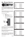
ALL ROOMS SCREEN
To access the All Rooms page, turn the Room
knob until the display to the right appears. Please
note, that since the HTR-2400 can have the room
names customized, your display may read slightly
different.
Once on the All Rooms page, you can see what
rooms/zones are off as well as rooms that are on
and what source is playing to it.
On this page you can:
1
Select a room.
2
Select a source to the room.
3
Turn the room off.
4
Adjust room volume (the display
will not indicate volume levels).
Front Plate
*THEATER ZONE
ROOM 1
ROOM 2
ROOM 3
ROOM 4
ROOM 5
ROOM 6
ROOM 7
ROOM 8
JAN
*THEATER ZONE
ROOM 1
ROOM 2
ROOM 3
ROOM 4
ROOM 5
ROOM 6
ROOM 7
ROOM 8
JAN
1
THEATER ZONE
*ROOM 1
ROOM 2
ROOM 3
ROOM 4
ROOM 5
ROOM 6
ROOM 7
ROOM 8
JAN
Press Knob
To Advance
1
1
THEATER ZONE
Side View
Chassis Side
To select a room you wish to control, repeatedly
press the Room knob. The * (cursor) will advance downward to the next room with each
press of the Room knob.
When you reach the last room, the next press of
the Room button will advance the * (cursor) to
the Theater Zone (top line).
If you turn the Room knob, the display will advance to other screens. When you return to the
All Rooms page, the * (cursor) will appear next
to the last selected room name.
Operation Instructions
Page 18
ROOM 1
*ROOM 2
ROOM 3
ROOM 4
ROOM 5
ROOM 6
ROOM 7
ROOM 8
JAN
1
THEATER ZONE
ROOM 1
ROOM 2
*ROOM 3
ROOM 4
ROOM 5
ROOM 6
ROOM 7
ROOM 8
JAN
1
THEATER OFF
ROOM
ROOM
ROOM
ROOM
ROOM
ROOM
ROOM
ROOM
12:01
OFF
OFF
OFF
OFF
OFF
OFF
OFF
OFF
AM
THEATER OFF
ROOM
ROOM
ROOM
ROOM
ROOM
ROOM
ROOM
ROOM
12:01
OFF
OFF
OFF
OFF
OFF
OFF
OFF
OFF
AM
THEATER OFF
ROOM
ROOM
ROOM
ROOM
ROOM
ROOM
ROOM
ROOM
12:01
OFF
OFF
OFF
OFF
OFF
OFF
OFF
OFF
AM
THEATER OFF
ROOM
ROOM
ROOM
ROOM
ROOM
ROOM
ROOM
ROOM
12:01
OFF
OFF
OFF
OFF
OFF
OFF
OFF
OFF
AM
THEATER OFF
ROOM
ROOM
ROOM
ROOM
ROOM
ROOM
ROOM
ROOM
12:01
OFF
OFF
OFF
OFF
OFF
OFF
OFF
OFF
AM
HTR-2400 Manual
ROOM 1
ROOM 2
ROOM 3
ROOM 4
ROOM 5
ROOM 6
ROOM 7
ROOM 8
JAN
s
T
*THEATER ZONE
o Select Sour
ce
nT
r
u
RC
SOU E
While the * (cursor) is set to the
Theater Zone, turning the Source
knob will scroll through only the
sources available in the home theater. Please note, these may differ from the sources accessible in
the other rooms/zones.
Front Plate
Once the desired
source is displayed, pressing
of the Source
knob will engage
that component.
If the theater was
off, this function
will also turn the
Theater on.
ROOM 1
ROOM 2
ROOM 3
ROOM 4
ROOM 5
ROOM 6
ROOM 7
ROOM 8
JAN
HTR-2400 Manual
1
ROOM OFF
ROOM OFF
ROOM OFF
ROOM OFF
*THEATER
ZONE
ROOM
OFF>DVD PLAYER 1
ROOM OFF
ROOM 1ROOM OFF ROOM OFF
ROOM 2ROOM OFF ROOM OFF
3
ROOM OFF
1ROOM 12:01
AM
ROOM 4
ROOM OFF
*THEATER ZONE >DSS
ROOM 5
ROOM OFF
ROOM 6
ROOM OFF
ROOM 1
ROOM
ROOM 7
ROOM OFF
ROOM 2
ROOM
ROOM 8
ROOM OFF
ROOM 3
ROOM
JAN
1
12:01 AM
ROOM 4
ROOM
ROOM 5
ROOM
ROOM 6
ROOM
ROOM 7
ROOM
ROOM 8
ROOM
JAN
1
12:01
*THEATER ZONE
Press Knob
To Engage
ROOM 1
ROOM 2
ROOM 3
ROOM 4
ROOM 5
ROOM 6
ROOM 7
ROOM 8
JAN
The Selected
Source Device
Side View
To select sources for additional
rooms, press the Room knob to
advance the * (cursor) to the desired room. Then, using the
Source knob, dial in the desired
source component. Once it is
displayed, press the Source
knob to engage the selection.
Please note, that sources used
in the eight house-wide rooms,
may differ from the sources available in the Theater Zone.
*THEATER ZONE
THEATER OFF
DSS
ROOM
ROOM
ROOM
ROOM
ROOM
ROOM
ROOM
ROOM
12:01
OFF
OFF
OFF
OFF
OFF
OFF
OFF
OFF
AM
DSS
ROOM
ROOM
ROOM
ROOM
ROOM
ROOM
ROOM
ROOM
12:01
2
OFF
OFF
OFF
OFF
OFF
OFF
OFF
OFF
AM
Chassis Side
THEATER ZONE
*ROOM 1
ROOM 2
ROOM 3
ROOM 4
ROOM 5
ROOM 6
ROOM 7
ROOM 8
JAN
2
OFF
OFF
OFF
OFF
OFF
OFF
OFF
OFF
AM
1
2
DVD PLAYER
>TUNER 1
ROOM OFF
THEATER
ZONE
ROOM
OFF DVD PLAYER
ROOM OFF
*ROOM 1
ROOM OFF >TUNER 2
ROOM 2
ROOM OFF
ROOM OFF
THEATER
ZONE ROOM
DVD OFF
PLAYER
ROOM
3
ROOM OFF
ROOM 4
ROOM OFF
ROOM OFF
*ROOM
TUNER
5 1 AM
ROOM
OFF 2
1ROOM
12:01
ROOM
ROOM
OFF
ROOM
6 2
ROOM
OFF
ROOM
ROOM
OFF
ROOM
7 3
ROOM
OFF
ROOM
ROOM
OFF
ROOM
8 4
ROOM
OFF
ROOM
ROOM
JAN 5 1
12:01
AM OFF
ROOM 6
ROOM OFF
ROOM 7
ROOM OFF
ROOM 8
ROOM OFF
JAN
1
12:01 AM
To turn off a room, press the Room
knob so that the * (cursor) is next
to the room name or number.
Then press the Off button situated
between the knobs. To turn off all
rooms, press and hold the Off button. The Theater Zone needs to
be turned off seperately.
Page 19
Operation Instructions
ROOM SCREEN (1-8)
To access a Room’s page, turn the Room knob
until the display to the right appears with the room
number or name that you wish to control. Once
on a Room’s page, you can see the room’s status as well as control:
1
Select a Source.
2
Adjust Volume.
3
Turn the room off.
4
Turn all rooms off (except Theater).
5
Adjust Bass Levels.
6
Adjust Midrange Levels.
7
Adjust Treble Levels.
8
Adjust Balance Levels.
9
Turn the Loudness Filter On & Off.
10
Turn the Limiter On & Off.
T
s
Selecting A Source (Turning On A Room)
If the room is off, selecting an input will turn it on.
To select an input, turn the Source knob. The
HTR-2400 permits you
Select Sou
o
scroll through the
rc
nT
e
ur
RC E
U
O
source components
S
connected to your system without immediately
switching away from
what you are already
using. The source
names that you could
select appear in the area marked “B” while the
current status of the room is shown in the area
marked as “A”.
Front Plate
To engage the selected
source (displayed in area
“B”), press the Press Knob
To Engage
Source knob.
The HTR-2400 The Selected
will switch inputs Source Device
and the new
source name appears in area “A”.
Side View
VOLUME 36
TUNER 2
BASS
MID
TREB
TONE
95.5
+ 6
+ 4
+ 7
1
1
ROOM 1
12:01 AM
VOLUME 36
TUNER 2
95.5
BASS + 6
ROOM +1 4
MID
A
TREB + 7
TUNER
TONE
1 2
BASS JAN
+ 6
MID
ROOM +1 4
TREB + 7
A
TONE
TUNER1 2
BASS
MID
TREB
TONE
FM
BALANCE EQUAL
LOUDNESS ON
LIMITER
ON
JAN
JAN
+ 6
+ 4
+ 7
1
JAN
FM
BALANCE EQUAL
VOLUME 36
LOUDNESS
ON
LIMITER
ON B
CD PLAYER 3
BALANCE
12:01
AM EQUAL
LOUDNESS
VOLUME 36ON
LIMITER
ON
B
CD LIBRARY 4
1
1
1
ROOM 1
12:01
AM EQUAL
BALANCE
LOUDNESS ON
LIMITER
ON
12:01 AM
VOLUME 36
CD LIBRARY 4
Chassis Side
Note that your source names may differ from what
is shown here. Also, the number following the
source name refers to the order of the inputs and
not the number of say CD players in the system.
Operation Instructions
ROOM 1
Page 20
BASS
MID
TREB
TONE
+ 6
+ 4
+ 7
1
JAN
BALANCE EQUAL
LOUDNESS ON
LIMITER
ON
1
12:01 AM
HTR-2400 Manual
T
Turning Off A Room or All Rooms
You can quickly turn off a room
by simply pressing the Room
Off button. If other rooms are
on (other than the Theater
Zone), the display will read ROOM OFF. To turn
off all rooms (other than the Theater Zone), press
and hold the Room Off button.
The Theater Zone must be turned off seperately
and does not turn off with the multi-room’s All Off
command.
Adjusting Bass, Midrange & Treble
To access the controls for bass, midrange, treble,
tone preset recalls, balance control, loudness filter and limiter, press the Volume knob.
e
Adjusting Volume
The volume can be raised or lowered using the
Volume knob.
o Adjust Volu
nT
m
r
u
UM
VOL E
ROOM 1
VOLUME 36
*ROOM OFF
BASS
ROOM+16
MID
+ 4
TREB
+
7
ALL OFF
TONE 1
BALANCE
VOLUME EQUAL
36
LOUDNESS ON
LIMITER
ON
BASS + 6
MID JAN
+ 4 1
TREB + 7
TONE 1
JAN
BALANCE EQUAL
12:01
AM
LOUDNESS
ON
LIMITER
ON
1
12:01 AM
Front Plate
Press Knob
To Advance
ROOM 1
VOLUME 36
TUNER 2
+ 6
+ 4
+ 7
1
JAN
BALANCE EQUAL
LOUDNESS ON
LIMITER
ON
Side View
1
12:01 AM
ROOM 1
95.5
BALANCE EQUAL
LOUDNESS ON
LIMITER
ON
JAN
1
VOLUME 36
TUNER 2
HTR-2400 Manual
95.5
+ 6
+ 4
+ 7
1
JAN
o Adjust Volu
nT
m
r
u
UME
L
O
V
12:01 AM
ROOM 1
BASS
MID
*TREB
TONE
FM
e
+ 6
+ 4
+ 7
1
Chassis Side
A * (cursor) will begin flashing next to the
first feature, BASS. Use the Volume knob
to raise or lower bass levels.
VOLUME 36
TUNER 2
BASS
*MID
TREB
TONE
To The Next
Feature
FM
T
*BASS
MID
TREB
TONE
95.5
FM
BALANCE EQUAL
LOUDNESS ON
LIMITER
ON
1
12:01 AM
Page 21
To advance to the next feature, press the
Volume knob. The * (cursor) will indicate
the next feature. Again, use the Volume
knob to adjust this feature.
Operation Instructions
ROOM SCREEN (CONT.)
Tone Preset Recall
The HTR-2400 features four tone presets per
room. These presets store tone levels and Loudness & Limiter filter settings and can be recalled
along with a fifth preset, Flat. If Flat is selected,
all levels (other than Balance) are set to 0 and
the Loudness Filter and Limiter are turned off.
In order for Presets 1 through 4 to operate, your
custom installation professional will have needed
to program the presets.
To recall a Tone Preset, press the Volume Knob
until the flashing * is on TONE. Turn the Volume
knob to the desired preset number (1-4) or the
letter “F” (for Flat). The recalling of the preset is
immediate and no other action is required.
Balance Adjustment
Balance allows you to compensate speaker levels to either the right or left speaker(s). To adjust
balance, press the Volume knob so that the * is
on BALANCE. Then turn the Volume knob to
move the balance level to the left or to the right.
Loudness Contour Filter (On or Off)
Loudness contour is an active filter that enhances
bass levels particularly at low volume levels. As
the rooms volume is increased the effect of this
filter is minimized. This permits the HTR-2400
to sound great even at background listening levels. To turn Loudness on or off, press the Volume knob so that the * is on LOUDNESS and
turn the Volume knob.
ROOM 1
TUNER 2
BASS
MID
TREB
*TONE
Exiting (regain use of the Volume knob)
a Press the Volume knob repeatedly until the *
has scrolled through all features or...
b Turn the Room knob to change screens or...
c Let the screen time out (30 seconds).
Operation Instructions
Page 22
95.5
+ 6
+ 4
+ 7
1
JAN
ROOM 1
BASS
MID
TREB
*TONE
1
1
95.5
+ 1
+ 7
+ 3
2
1
95.5
+ 1
+ 7
+ 3
2
FM
BALANCE R 3
*LOUDNESS ON
LIMITER
OFF
1
ROOM 1
12:01 AM
VOLUME 36
TUNER 2
95.5
+ 1
+ 7
+ 3
2
JAN
12:01 AM
VOLUME 36
TUNER 2
BASS
MID
TREB
TONE
FM
*BALANCE R 3
LOUDNESS ON
LIMITER
OFF
ROOM 1
BASS
MID
TREB
TONE
12:01 AM
VOLUME 36
TUNER 2
JAN
FM
BALANCE EQUAL
LOUDNESS ON
LIMITER
OFF
ROOM 1
BASS
MID
TREB
TONE
12:01 AM
VOLUME 36
95.5
+ 1
+ 7
+ 3
2
JAN
FM
BALANCE EQUAL
LOUDNESS ON
LIMITER
ON
TUNER 2
JAN
Limiter
The HTR-2400 features a digital limiter which
prevents clipping. To turn this feature on or off,
press the Volume knob until the * is on LIMITER
and then turn the Volume knob to turn this feature on or off.
VOLUME 36
FM
BALANCE R 3
LOUDNESS ON
*LIMITER
OFF
1
12:01 AM
HTR-2400 Manual
elect Sc
To S
ree
rn
n
u
T
O
O
M
R
PARTY GROUP SCREEN
To access Party Group control, turn the room
knob until the screen shows the Party Group
page.
PARTYGROUP 1
*ROOM
*ROOM
*ROOM
ROOM
1
2
3
4
In order for this feature to operate, your
installation professional must have already
assigned rooms to one (or more) of the
four available Party Groups. A * will appear next to rooms that are assigned to
the Party Group. To advance through all
four Party Groups, repeatedly press the
Room knob.
XM TUNER 1
ROOM
ROOM
*ROOM
ROOM
5
6
7
8
JAN
1
12:01 AM
PARTYGROUP 2
XM TUNER 1
*ROOM
ROOM
ROOM
*ROOM
1
2
3
4
*ROOM
*ROOM
*ROOM
ROOM
Front Plate
5
6
7
8
Press Knob
To Advance
Through The
4 Party Groups
JAN
1
12:01 AM
PARTYGROUP 3
XM TUNER 1
ROOM
ROOM
ROOM
ROOM
1
2
3
4
*ROOM
*ROOM
ROOM
*ROOM
5
6
7
8
Side View
*ROOM
*ROOM
*ROOM
*ROOM
1
2
3
4
JAN
*ROOM
*ROOM
*ROOM
*ROOM
1
Then press the Source
knob to engage that input to the rooms in the
Party Group.
T
E
To select a source for a Party Group, turn
the Source knob until the desired component is displayed.
Front Plate
PARTYGROUP 4
> FM TUNER 2
PARTYGROUP
4
*ROOM
1
*ROOM
2
*ROOM
3
PARTYGROUP
*ROOM
*ROOM
41
*ROOM
2
*ROOMJAN
3
1
*ROOM 4 1
*ROOM
*ROOM
2
*ROOMJAN
3 1
*ROOM
4
Press Knob
To Engage
The Selected
Source Device
HTR-2400 Manual
SO
5
6
7
8
12:01 AM
Side View
o Select Sour
ce
nT
ur
URC
s
JAN
1
12:01 AM
PARTYGROUP 4
XM TUNER 1
Chassis Side
JAN
1
> CD PLAYER
3
*ROOM
5
*ROOM
6
*ROOM
7
4*ROOM
CD 8PLAYER
3
*ROOM
5
*ROOM
6
*ROOMAM 7
12:01
*ROOM 8 5
*ROOM
*ROOM
6
*ROOM
12:01 AM 7
*ROOM
8
12:01 AM
Chassis Side
Page 23
Operation Instructions
ENTERING SETUP MODE
The code to enter the HTR-2400’s setup menu
is 1867. To enter the setup section of the HTR2400, press and hold the Mode knob for 5 seconds until the display reads:
SETUP
Front Plate
MODE
M
Press & Hold
Knob To Enter
|
ENTER CODE XXXX
Setup
Feature
BUTTON/ENCODER TEST
Dial Code 1
To
86
se
UM
VOL E
7
U
Side View
Turn the Volume knob
until the first X is replaced by the number
1 in the code 1867.
Chassis Side
SETUP
M
|
ENTER CODE 1XXX
BUTTON/ENCODER TEST
Turn the Mode knob to advance the cursor to the next
position. Again use the
Volume knob to dial in the
number 8. Repeat this until the code 1867 is displayed.
vance Cursor
Ad
SETUP
MODE
SETUP
M
|
ENTER CODE 18XX
BUTTON/ENCODER TEST
M
|
ENTER CODE 186X
SETUP
BUTTON/ENCODER TEST
M
|
ENTER CODE 1867
BUTTON/ENCODER TEST
MAIN SETUP MENU
MODE
When the code 1867 is displayed,
press and release the Mode knob.
M
> HOME THEATER
PARTY
TONE
INPUT TRIMS
LABELS/SOURCE
ADA BUS
AC POWER
VOLUME
VERSION
BALANCE
CLOCK SET
FACTORY DEFAULT
Multi-Room Setup
Page 24
HTR-2400 Manual
NAVIGATING SETUP MODE
The HTR-2400’s on-screen menu system is very
easy to navigate. Most features are accessed
by turn the Mode knob and entered by pressing
the knob. The Volume knob and occasionally,
the Room knob are used to access other features. Once you have begun working with the
HTR-2400’s setup, the function of turning and
pressing the appropriate knobs will become self
evident.
An arrow will display next to the feature you are
on.
To exit the setup area from any page, move the
arrow to the letter “M” using the Mode knob. Then
press the Mode knob.
If you wish to return to a previous Setup page,
move the arrow to the letter “P” and press the
Mode knob.
UM
VOL E
MODE
MAIN SETUP MENU
M
> HOME THEATER
PARTY
TONE
INPUT TRIMS
LABELS/SOURCE
MAIN
SETUP MENU
M>
ADA BUS
AC POWER
VOLUME
VERSION
HOME THEATER
BALANCE
CLOCK SET
PARTY
TONE
HT MAIN SETUP MENU
<P M
INPUT TRIMS
LABELS/SOURCE
FACTORY
DEFAULT
ADA BUS
AC POWER
HT SPEAKER
VOLUME
VERSION
HT SOURCE
BALANCE
CLOCK SET
HT GLOBAL
HT TONE
FACTORY DEFAULT
HT PROLOGIC IIx
HT INFORMATION
MULTI-ROOM & GLOBAL SETUPS
The Main Setup Menu provides you with eight
pages in addition to the Home Theater setup
menus. Other than a few ADA Bus features, the
Version page and the Clock page, the options
discussed here only apply to the eight housewide rooms and not the Home Theater. The
Home Theater is setup on its own series of pages.
This page also permits you to reset the HTR2400 to the ADA Factory Defaults.
Party - Assign rooms to up to four Party Groups.
Party Groups can be used to force zones to track
each other’s sources or to make turning on several rooms easy when entertaining.
MAIN SETUP MENU
M
HOME THEATER
>PARTY
TONE
INPUT TRIMS
LABELS/SOURCE
ADA BUS
AC POWER
VOLUME
VERSION
BALANCE
CLOCK SET
FACTORY DEFAULT
Volume - Set a room’s maximum volume
level, store up to four volume presets and
determine if the room turns on to Volume,
Tone & Balance Presets 1 or what was
last used.
Input Trims - Raise or lower the source’s audio
level so that as inputs are switched, the levels
are similar.
Balance - Set balance levels and presets.
ADA Bus - Set the maximum number of rooms
and inputs on the house-wide system. You can
also turn the HTR-2400’s front panel IR receiver
on or off as well as set time outs for the GUI and
display (including all LEDs).
AC Power - Assign AC outlets to sources.
HTR-2400 Manual
Page 25
Tone - Set tone levels, filters and presets.
Version - Display HTR-2400 version #s.
Clock - Set the clock & time format.
Multi-Room Setup
o Select Roo
m
nT
ur
MODE
#
T
PARTY MODE SETUP
Party Mode permits you to
have rooms track a specific
Party Group number. Use
the Mode knob to advance
through room numbers/
names. The arrow will point
to the room selected.
PARTY SETUP
1
2
3
4
5
6
7
8
|
PARTY 1 2 3 4
*
*
*
M
HOME THEATER
>PARTY
TONE
INPUT TRIMS
LABELS/SOURCE
ADA BUS
AC POWER
VOLUME
VERSION
BALANCE
CLOCK SET
FACTORY DEFAULT
t Party Gro
up
lec
Se
P M
The Room knob is used to
select the Party Group you
wish to edit. Turning the
room knob will advance the
arrow over the Party Group
number.
R OOM
* *
PARTY SETUP
Par
Off
ty
ty
O
ar
U
M
L
E
VO
n
The Volume knob is used to
make a room part of a Party
Group. Rotating it clockwise turns Party On. A *
(star) indicates that Party is
On. Turning it counterclockwise turns Party Off.
P
ROOM
ROOM
ROOM
>ROOM
ROOM
ROOM
ROOM
ROOM
MAIN SETUP MENU
ROOM
ROOM
ROOM
ROOM
ROOM
>ROOM
ROOM
ROOM
1
2
3
4
5
6
7
8
P M
|
PARTY 1 2 3 4
*
*
*
* *
*
INPUT TRIM SETUP
The adjustment of Input Trim levels is a feature
that helps maintain even volume levels when
switching between sources. The Mode knob advances through Source Names. The arrow will
indicate which source you are on.
or Lower Tr
im
ise
a
s
R
UME
L
O
V
To Select Inp
rn
ut
Tu
MODE
MAIN SETUP MENU
M
HOME THEATER
PARTY
TONE
>INPUT TRIMS
LABELS/SOURCE
ADA BUS
AC POWER
VOLUME
VERSION
BALANCE
CLOCK SET
FACTORY DEFAULT
The Volume knob is used to raise or lower
Input Trim levels for each source.
INPUT TRIM SETUP
XM TUNER
>FM TUNER
CD PLAYER
CD LIBRARY
SATELLITE
CABLE BOX
DVD PLAYER
AUXILIARY
Multi-Room Setup
P M
INPUT TRIM SETUP
= -3dB
= +2dB
=
0dB
=
0dB
=
0dB
=
0dB
=
0dB
=
0dB
>XM TUNER
FM TUNER
CD PLAYER
CD LIBRARY
SATELLITE
CABLE BOX
DVD PLAYER
AUXILIARY
Page 26
P M
= -3dB
=
0dB
=
0dB
=
0dB
=
0dB
=
0dB
=
0dB
=
0dB
HTR-2400 Manual
T
o Adjust Set
tin
nT
ur
UME
L
O
V
g
o Select Feat
ur
nT
ur
e
T
ADA BUS SETUP
MODE
The ADA Bus Setup page allows you to set two
multi-room specific features and three global features. Use the Mode knob to select the feature
and the Volume knob to adjust it.
ADA BUS SETUP
MAIN SETUP MENU
M
HOME THEATER
PARTY
TONE
INPUT TRIMS
LABELS/SOURCE
>ADA BUS
AC POWER
VOLUME
VERSION
BALANCE
CLOCK SET
FACTORY DEFAULT
The Max Room features lets you limit the
number of rooms that the user sees when
they turn the Room knob. This effectively
reduces the number of rooms. So if you
are using only five multi-room zones, you
can set the Max Room to equal 5.
P M
>MAX ROOM = 8
MAX INPUT= 8
IR RECEIVER=ON
BACKLIGHT TIMEOUT=NONE
ADA BUS SETUP
OSD TIMEOUT=NONE
P M
MAX ROOM = 8
The Max Input is much like the Max Room feature where you can limit the number of inputs on
the unit. Like the Max Room feature, the upper
inputs do not display and you may need to rename your lower sources to match the system.
>MAX INPUT= 8
IR RECEIVER=ON
BACKLIGHT TIMEOUT=NONE
OSD TIMEOUT=NONE
ADA BUS SETUP
P M
IR Receiver refers the HTR-2400’s front
panel IR receiver. If you notice interference from IR emitting sources, try turning
the IR receiver off.
MAX ROOM = 8
MAX INPUT= 8
>IR RECEIVER=ON
ADA BUS SETUP
BACKLIGHT TIMEOUT=NONE
MAX ROOM = 8
OSD TIMEOUT=NONE
Back Light Timeout refers to not just the video
display but also all of the buttons. The HTR2400 can go completely dark in 1 to 60 seconds
or stay on all the time whenever a zone is on.
ADA BUS SETUP
MAX INPUT= 8
IR RECEIVER=ON
>BACKLIGHT TIMEOUT=NONE
OSD TIMEOUT=NONE
P M
The OSD (On Screen Display or GUI) can
be set to time out independent of the video
display. Set in one second increments,
the OSD can time out in 1 to 60 seconds
or remain on indefinitely. If you have set
the Back Light to time out sooner than the
OSD, then the display will blank earlier.
MAX ROOM = 8
MAX INPUT= 8
IR RECEIVER=ON
BACKLIGHT TIMEOUT=NONE
>OSD TIMEOUT=NONE
HTR-2400 Manual
P M
Page 27
Multi-Room Setup
VOLUME SETUP
UM
VOL E
o Select Feat
ur
nT
ur
MODE
TURN ON WITH LAST USED
1
2
3
4
RECALL
RECALL
RECALL
RECALL
1
2
3
4
VOLUME SETUP
P M
>ROOM
1
VOLUME=45
VOLUME MAX=80
VOLUME SETUP
P M
>ROOMON 3WITH LAST USED
TURN
VOLUME=45
VOLUME MAX=80
STORE 1
RECALL 1
TURN 2
ON WITHRECALL
LAST USED
STORE
2
STORE 3
RECALL 3
STORE4 1
RECALL4 1
STORE
RECALL
STORE 2
RECALL 2
STORE 3
RECALL 3
STORE 4
RECALL 4
Volume Preset 1 can be used as the turn
on preset volume level.
Turn the Mode knob to advance to the next feature, Volume Max, which refers to the maximum
volume level the room can reach. This feature is
useful to prevent a room from either distorting or
playing louder than intended. Use the Volume
knob to adjust the room’s maximum volume level.
Turn the Mode knob to advance to the next feature, Turn On With, which determines if the room
will turn on to its last acoustical settings used or
turn on to a preset acoustical setting. The preset number recalled involves all Preset 1 functions, including Volume, Tones, and Balance. As
such, this feature is ideal for starting at the perfect acoustical level each and every time the room
is turned on. To alter between Last Used or Preset Recall number 1, turn the Volume knob.
Multi-Room Setup
FACTORY DEFAULT
When on Volume, you can alter a rooms
volume level. This is useful for setting up
the four Volume Presets. Alternately, you
could also adjust the room’s volume level
from its keypad or control.
VOLUME SETUP
P M
ROOM
3
>VOLUME=53
VOLUME MAX=80
STORE
STORE
STORE
STORE
M
HOME THEATER
PARTY
TONE
INPUT TRIMS
LABELS/SOURCE
ADA BUS
AC POWER
>VOLUME
VERSION
BALANCE
CLOCK SET
n
e
Once the desired room is
selected, turning the
Mode knob advances the
arrow to the next feature.
T
When the arrow is on the
room name/number, turning the Volume knob permits you to cycle through
the eight rooms on the
system.
ur
MAIN SETUP MENU
g
T
On the Volume Setup page, one can set volume
parameters for all eight rooms of the whole-house
system. This includes setting a room’s maximum
volume level, storing volume presets, and selecting if a room turns on to the last acoustical settings used in that room or to all presets stored on
Preset 1 (including Volume, Tones, and Balance
o Adjust Set
Presets 1).
ti
nT
Page 28
VOLUME SETUP
P M
ROOM
3
VOLUME=53
>VOLUME MAX=65
TURN ON WITH LAST USED
STORE
STORE
STORE
STORE
1
2
3
4
RECALL
RECALL
RECALL
RECALL
1
2
3
4
VOLUME SETUP
P M
ROOM
3
VOLUME=53
VOLUME MAX=65
>TURN ON WITH RECALL 1
STORE
STORE
STORE
STORE
1
2
3
4
RECALL
RECALL
RECALL
RECALL
1
2
3
4
HTR-2400 Manual
Storing Volume Presets first requires that the
desired volume level is displayed. Once the correct volume level has been dialed in, turn the
Mode knob to advance the arrow to the preset
you wish to store (STORE 1 - 4).
MODE
Then press the Mode knob to
Store the preset. The display will
momentarily display the word
OK and then return to showing
the word STORE #.
Press Mode To Store
>STORE 1
STORE 2
VOLUME3 SETUP
STORE
ROOM 4 3
STORE
VOLUME=53
RECALL
RECALL
RECALL
RECALL
VOLUME
1
2
P M
3
4
MAX=65
1
2
3
4
BALANCE SETUP
1
2
3
4
RECALL
RECALL
RECALL
RECALL
1
2
3
4
MAIN SETUP MENU
On the Balance Setup page, you can alter the
balance level of the room as well as store two
Balance Presets. Balance Preset 1 can be used
as the turn on balance level.
BALANCE SETUP
>ROOM
1
OK
STORE
STORE
STORE
MODE
TURN ON WITH RECALL 1
RECALL
>RECALL
RECALL
RECALL
>
To recall a Volume Preset,
turn the Mode knob so that
the arrow is on the preset
number you wish to Recall.
Then press the Mode knob
to Recall this level. Assuming different volume levels
Press Mode To Recall have been stored on the four
presets, you should see the VOLUME levels at the top of the screen change.
VOLUME SETUP
P M
ROOM
3
VOLUME=53
VOLUME MAX=65
1
2
3
4
TURN ON WITH RECALL 1
TURN ON WITH RECALL 1
Again, Volume Preset 1 is the preset used for
room turn on volume recall.
STORE
STORE
STORE
STORE
VOLUME SETUP
P M
ROOM
3
VOLUME=53
VOLUME MAX=65
P M
M
HOME THEATER
PARTY
TONE
INPUT TRIMS
LABELS/SOURCE
ADA BUS
AC POWER
VOLUME
VERSION
>BALANCE
CLOCK SET
FACTORY DEFAULT
BALANCE=EQUAL
BALANCE
SETUP
STORE
1
RECALL 1
ROOM2 1
STORE
RECALL 2
>BALANCE=RIGHT
P M
4
STORE 1
RECALL 1
STORE 2
RECALL 2
BALANCE SETUP
ROOM
1
BALANCE=RIGHT
>STORE 1
STORE 2
HTR-2400 Manual
Like the Volume Page, use the Mode knob
to advance through features and the Volume knob to adjust Balance levels. When
you are ready to store a Balance Preset,
navigate to the Store # and then press the
Mode knob. The display will echo OK.
P M
4
BALANCE SETUP
ROOM
1
P M
BALANCE=EQUAL
RECALL 1
RECALL 2
STORE 1
STORE 2
Page 29
RECALL 1
>RECALL 2
Multi-Room Setup
TONE SETUP
MAIN SETUP MENU
HOME THEATER
PARTY
>TONE
INPUT TRIMS
LABELS/SOURCE
ADA BUS
AC POWER
VOLUME
VERSION
BALANCE
CLOCK SET
The Tone Setup page permits you to adjust Bass,
Midrange, and Treble levels as well as turn on or
off the Loudness contour filter and the Limiter.
You can also store up to four Tone Presets on
this page. Again, Tone Preset 1 can be used as
the Turn On preset which will include levels and
filters.
TONE SETUP
>ROOM
1
RECALL
RECALL
RECALL
RECALL
Use the Volume knob to set levels or turn
the Loudness and Limiter on and off.
P M
LOUDNESS
OFF
LIMITER
OFF
SET ALL FLAT
TONE RECALL
SETUP
ROOM
1
RECALL
RECALL
BASS
+ 5
RECALL
>MID
- 1
TREB
0
STORE
STORE
STORE
STORE
P M
1
2
3
OFF
4 LOUDNESS
LIMITER
OFF
SET ALL FLAT
TONE SETUP
P M
1
RECALL 1
1
2 ROOM RECALL
2
3
RECALL 3
5
LOUDNESS
OFF
4 BASS +RECALL
4
MID
- 1
LIMITER
OFF
>TREB + 3
SET ALL FLAT
STORE
STORE
STORE
STORE
The Loudness contour filter is an
active filter that enhances bass levels especially at low volume levels.
As volume is increased the effect
of the Loudness filter is lowered.
1
RECALL 1
TONE
SETUP
2ROOM
RECALL
2
1
3
RECALL 3
4BASS + RECALL
4
5
>LOUDNESS
MID
- 1
TREB + 3
STORE
STORE
STORE
STORE
1
2
3
4
The Limiter filter assists in preventing volume
peaks from being too loud, especially when the
volume level is high. At high levels, the limiter
helps prevent sharp spikes in volume.
Multi-Room Setup
o Adjust Sett
nT
in
r
u
UME
L
O
V
g
1
2
3
4
eat
ur
o
nT
ur
MODE
1
2
3
4
TONE SETUP
ROOM
1
STORE
STORE
STORE
STORE
T
LOUDNESS
OFF
LIMITER
OFF
SET ALL FLAT
1
2
3
4
>BASS + 5
MID
0
TREB
0
Use the Mode knob to navigate between
features.
Select F
P M
T
STORE
STORE
STORE
STORE
0
0
0
FACTORY DEFAULT
e
BASS
MID
TREB
M
Page 30
P M
ON
LIMITER
OFF
SET ALL FLAT
RECALL
TONE
SETUP1
P M
RECALL
ROOM
1 2
RECALL 3
RECALL
BASS
+ 5 4
LOUDNESS
ON
MID
- 1
>LIMITER
ON
TREB + 3
SET ALL FLAT
STORE
STORE
STORE
STORE
1
2
3
4
RECALL
RECALL
RECALL
RECALL
1
2
3
4
HTR-2400 Manual
The Set All Flat function sets all levels back to 0 and turns the Loudness and Limiter filters off.
TONE SETUP
ROOM
1
BASS + 5
MID
- 1
TREB + 3
To return all levels to 0, navigate to
the Set All Flat feature using the
Mode knob and then press the
Mode knob.
STORE
STORE
STORE
STORE
MODE
1
2
3
4
LOUDNESS
ON
LIMITER
ON
>SET ALL FLAT
RECALL
TONE SETUP
RECALL
ROOM
1
RECALL
RECALL
BASS
0
MID
0
TREB
0
STORE
STORE
STORE
STORE
Press Mode To Set Flat
TONE SETUP
ROOM
1
BASS + 5
MID
- 1
TREB + 3
>STORE
STORE
STORE
STORE
P M
RECALL 1
RECALL 2
RECALL 3
RECALL 4
TONE SETUP
ROOM
1
The screen will momentarily display the
word OK indicating that
the settings have been
stored.
OK
STORE
STORE
STORE
TONE SETUP
ROOM
1
STORE
STORE
STORE
STORE
RECALL
RECALL
>RECALL
RECALL
1
2
3
4
RECALL
RECALL
RECALL
RECALL
1
2
3
4
LOUDNESS
ON
LIMITER
ON
SET ALL FLAT
RECALL
RECALL
RECALL
RECALL
P M
LOUDNESS
ON
LIMITER
ON
SET ALL FLAT
LOUDNESS
OFF
LIMITER
OFF
>SET ALL FLAT
MODE
1
2
3
4
BASS + 5
MID
- 1
TREB + 3
P M
P M
BASS + 5
MID
- 1
TREB + 3
>
1
2
3
4
1
2
3
4
To Store a Tone Preset, which will include
Bass, Midrange and Treble levels as well
as the Loudness Filter and Limiter Filter
status, turn the Mode knob to the Preset
Store number you wish to save and then
press the Mode knob. Again, Tone Preset
1 can be used as the Turn On preset.
LOUDNESS
ON
LIMITER
ON
SET ALL FLAT
1
2
3
4
P M
1
2
3
4
1
2
3
4
Press Mode To Store
To recall a Tone Preset level, turn the Mode
knob until the arrow is on the Recall number whose settings you wish to load. Then
press the Mode knob to recall that Tone
Preset number.
TONE SETUP
ROOM
1
MODE
P M
BASS + 8
MID
+ 3
TREB + 5
LOUDNESS
ON
LIMITER
OFF
SET ALL FLAT
STORE
STORE
STORE
STORE
RECALL
RECALL
>RECALL
RECALL
1
2
3
4
1
2
3
4
Press Mode To Recall
HTR-2400 Manual
Page 31
Multi-Room Setup
LABELS & SOURCE SETUP
On the Labels & Source Setup page, you can
relabel the room and source names to customize the system. Here you can also assign the
source’s secondary function to the input #/source
name and load this program to system keypads.
This will be discussed on the next page.
LABELS/SOURCE SETUP
P M
|
>ROOM
1
ROOM
1
|
INPUT
1
XM TUNER
MAIN SETUP MENU
M
HOME THEATER
PARTY
TONE
INPUT TRIMS >LABELS/SOURCE
ADA BUS
AC POWER
VOLUME
VERSION
BALANCE
CLOCK SET
SOURCE TYPE = ADA TUNER
ADDRESS
= TUNER 1 MOD 1
o Select Feat
ur
nT
r
u
MODE
e
T
FACTORY DEFAULT
PROGRAM ALL
A vertical arrow indicates the character that
can be changed. Using
the Source knob,
change the first character as needed (in this
example, we are going
to relabel ROOM 1 to
LIVING RM).
Use the Mode knob to
navigate between features. The horizontal arrow will indicate which
feature you are on. Use
the Volume knob to advance through rooms or
sources (inputs).
S
s
LABELS/SOURCE SETUP
P M
ooms/So
|
ur
ts R
ce
ec
>ROOM
1
LOOM
1
l
e
U
M
L
O
E
V
|
LABELS/SOURCE
SETUP
P M
INPUT
1
XM
TUNER
|
>ROOM TYPE
1 = ADALIOM
SOURCE
TUNER1
|
ADDRESS
= TUNER
1 MOD 1 P M
LABELS/SOURCE
SETUP
INPUT
1
XM TUNER
|
PROGRAM
ALL 1
>ROOM
LIVM
1
SOURCE TYPE = ADA TUNER
|
ADDRESS
= TUNER
1 MOD 1 P M
LABELS/SOURCE
SETUP
INPUT
1
XM
TUNER
ges Characte
n
|
a
rs
PROGRAM
ALL 1
Ch
>ROOM
LIVI
1
R
C
U
SOURCE TYPE = ADA TUNER
E
SO
|
ADDRESS
= TUNER
1 MOD 1 P M
LABELS/SOURCE
SETUP
INPUT
1
XM
TUNER
|
PROGRAM
ALL 1
>ROOM
LIVIN
1
SOURCE TYPE = ADA TUNER
|
ADDRESS
= TUNER
1 MOD 1 P M
LABELS/SOURCE
SETUP
INPUT
1
XM TUNER
|
PROGRAM
>ROOMALL 1
LIVING1
SOURCE TYPE = ADA TUNER
|
Use the Room knob to advance
ADDRESS
= TUNER
1 MOD 1 P M
LABELS/SOURCE
SETUP
INPUT
1
XM
TUNER
the vertical arrow to the next char|
PROGRAM
acter position. Repeat the char>ROOMALL
1 = ADA
LIVING
SOURCE
TYPE
TUNER
|
ADDRESS
= TUNER
1 MOD 1
acter change using the Source
LABELS/SOURCE
SETUP
P M
INPUT
1
XM
TUNER
knob. Continue this process for
|
PROGRAM ALL
>ROOM TYPE
1 = ADA
LIVING
all letters of the room name.
SOURCE
TUNER R
|
ADDRESS
= TUNER 1 MOD 1
Letter Posi
LABELS/SOURCE
SETUP
P M
INPUT
1
XM
TUNER
es
tio
ov
n
|
M
PROGRAM ALL
>ROOM TYPE
1 = ADA
LIVING
SOURCE
TUNER RM
R OOM
|
ADDRESS
= TUNER 1 MOD 1
INPUT
1
XM TUNER
PROGRAM ALL
SOURCE TYPE = ADA TUNER
ADDRESS
= TUNER 1 MOD 1
Repeat these steps for other room names and
sources as needed.
Multi-Room Setup
Page 32
PROGRAM ALL
HTR-2400 Manual
SOURCE CONTROL SETUP
The Source Control setup permits you to
assign the secondary source transport functions to the inputs/source names on your
system. The chart to the right details the
various source types and addresses. Those
marked in bold are most typically used.
SOURCE TYPE
ADDRESSES
BOLD ADDRESS
INDICATES MOST
COMMON DEVICES
LABELS/SOURCE SETUP
ROOM
1
INPUT
1
P M
|
LIVING RM
|
XM TUNER
>SOURCE TYPE = ADA TUNER
ADDRESS
= TUNER 1 MOD 1
LABELS/SOURCE SETUP
PROGRAM ALL
ROOM
1
INPUT
4
P M
|
LIVING RM
|
CD LIBRARY
T
o Select Feat
ur
nT
ur
MODE
e
>SOURCE TYPE = IR LEARNER
ADDRESS
= IRL 1
OUT 4
IR LEARNER
IRL 1 OUT 1
IRL 1 OUT 2
IRL 1 OUT 3
IRL 1 OUT 4
IRL 1 OUT 5
IRL 1 OUT 6
IRL 1 OUT 7
IRL 1 OUT 8
IRL 2 OUT 1
IRL 2 OUT 2
IRL 2 OUT 3
IRL 2 OUT 4
IRL 2 OUT 5
IRL 2 OUT 6
IRL 2 OUT 7
IRL 2 OUT 8
.
.
.
IRL 9 OUT 1
IRL 9 OUT 2
IRL 9 OUT 3
IRL 9 OUT 4
IRL 9 OUT 5
IRL 9 OUT 6
IRL 9 OUT 7
IRL 9 OUT 8
LABELS/SOURCE
SETUP
PROGRAM
ALL
ROOM
1
INPUT
1
P M
|
LIVING RM
|
XM TUNER
>SOURCE TYPE = SPECIAL CD
ADDRESS
= SPECIAL CD 1
LABELS/SOURCE SETUP
PROGRAM ALL
ROOM
1
INPUT
1
P M
|
LIVING RM
|
XM TUNER
>SOURCE TYPE = LVI
ADDRESS
= LVI 1
LABELS/SOURCE SETUP
PROGRAM ALL
ROOM
1
INPUT
1
P M
|
LIVING RM
|
XM TUNER
ADA TUNER
SPECIAL CD
LVI
TUNER 1 MOD 1 SPECIAL CD 1 LVI 1
TUNER 1 MOD 2 SPECIAL CD 2 LVI 2
TUNER 1 MOD 3
SPECIAL CD 3
LVI 3
TUNER 2 MOD 1
SPECIAL CD 4
LVI 4
TUNER 2 MOD 2
SPECIAL CD 5
LVI 5
TUNER 2 MOD 3
SPECIAL CD 6
LVI 6
TUNER 3 MOD 1
SPECIAL CD 7
LVI 7
TUNER 3 MOD 2
SPECIAL CD 8
LVI 8
TUNER 3 MOD 3
TUNER 4 MOD 1
TUNER 4 MOD 2
TUNER 4 MOD 3
TUNER 5 MOD 1
TUNER 5 MOD 2
TUNER 5 MOD 3
TUNER 6 MOD 1
TUNER 6 MOD 2
TUNER 6 MOD 3
TUNER 7 MOD 1
TUNER 7 MOD 2
TUNER 7 MOD 3
TUNER 8 MOD 1
TUNER 8 MOD 2
TUNER 8 MOD 3
TUNER 9 MOD 1
TUNER 9 MOD 2
TUNER 9 MOD 3
Use the Mode knob to
cycle between setup
options and the Volume
knob to change Inputs,
Source Types and then
Source Addresses.
The chart below
shows the HTR2400’s out of the box
Source Control setup.
It’s internal tuners are
always ADA Tuner 1,
Modules 1 and 2.
INPUT #
INPUT 1
INPUT 2
INPUT 3
INPUT 4
INPUT 5
INPUT 6
INPUT 7
INPUT 8
>SOURCE TYPE = NONE
ADDRESS
=
NONE
SOURCE NAME
XM TUNER
FM TUNER
CD PLAYER
CD LIBRARY
SATELLITE
CABLE BOX
DVD PLAYER
AUXILIARY
e Type/Addre
urc
ss
o
S
OLUM
E
V
SOURCE TYPE
ADA TUNER
ADA TUNER
IR LEARNER
IR LEARNER
IR LEARNER
IR LEARNER
IR LEARNER
IR LEARNER
ADDRESS
TUNER 1 MOD 1
TUNER 1 MOD 2
IRL 1 OUT 3
IRL 1 OUT 4
IRL 1 OUT 5
IRL 1 OUT 6
IRL 1 OUT 7
IRL 1 OUT 8
If you are using an iHome Multi-Center CD
Server, you will need to assign the server’s
inputs to Special CD settings.
PROGRAM ALL
LABELS/SOURCE SETUP
Once the Source Control Setup
is completed, you can Upload
these settings to both keypads
and the HTR-2400’s front panel.
Just like an ADA keypad, the buttons flanking the HTR-2400’s
screen require programming.
MODE
ROOM
1
INPUT
4
P M
|
LIVING RM
|
CD LIBRARY
SOURCE TYPE = SPECIAL CD
ADDRESS
= SPECIAL CD 2
>
UPLOADING > > > > >
Press Mode To Program All
HTR-2400 Manual
Page 33
Multi-Room Setup
AC POWER SETUP
MAIN SETUP MENU
The AC Power Setup page permits you to have
the HTR-2400’s four AC power outlets turn on
and off with specific source inputs. The Home
Theater setup offers a feature similar to this.
P M
|
AC OUTLET 1 2 3 4
>XM TUNER
FM TUNER
CD PLAYER
*
CD LIBRARY
*
SATELLITE
CABLE BOX
DVD PLAYER
*
AUXILIARY
*
HOME THEATER
PARTY
TONE
INPUT TRIMS
LABELS/SOURCE
ADA BUS
>AC POWER
VOLUME
VERSION
BALANCE
CLOCK SET
AC POWER SETUP
P M
|
AC OUTLET 1 2 3
XM TUNER
FM TUNER
>CD PLAYER
*
CD LIBRARY
*
AC POWER SETUP
SATELLITE
|
CABLE BOX
AC OUTLET 1 2
DVD PLAYER
*
XM TUNER
AUXILIARY
FM TUNER
>CD PLAYER
CD LIBRARY
*
SATELLITE
CABLE BOX
DVD PLAYER
AUXILIARY
AC POWER SETUP
O
ts AC Oute
lec
ts
Se
R OOM
AC POWER SETUP
*
*
*
UM
VOL E
P M
|
AC OUTLET 1 2 3 4
XM TUNER
FM TUNER
CD PLAYER
CD LIBRARY
SATELLITE
>CABLE BOX
*
DVD PLAYER
*
AUXILIARY
*
Multi-Room Setup
The Room knob is
used to select the
AC Outlet number. A
vertical arrow indicates which outlet is
being adjusted.
3 4
AC Oultet
ff
The Mode knob advances through the
source inputs. A horizontal arrow indicates which
source is being adjusted.
P M
O
n
The Volume knob is used
to turn the selected AC
Outlet to turn on and off
with the Source indicated. When an AC Outlet is set to track a
source, a * will appear.
4
o Select Sou
nT
rc
ur
MODE
e
T
FACTORY DEFAULT
The above screen display represents the ADA
out of the box setup.
AC POWER SETUP
M
P M
|
AC OUTLET 1 2 3 4
XM TUNER
FM TUNER
CD PLAYER
>CD LIBRARY
*
SATELLITE
AC POWER
P M
CABLE
BOX SETUP
DVD PLAYER
*|
AUXILIARY AC OUTLET 1 2 *3 4
XM TUNER
FM TUNER
CD PLAYER
>CD LIBRARY
SATELLITE
CABLE BOX
DVD PLAYER
*
AUXILIARY
*
Note that certain sources require constant AC
power and as such, should not be plugged
into the HTR-2400’s switched AC Outlets.
For a source component with two or more
audio outputs that can be switched on and
off via one AC Outlet, the HTR-2400 permits
multiple source inputs to activate a single AC
Outlet.
Page 34
HTR-2400 Manual
VERSION INFORMATION
From time to time, it may be
necessary to access the software/firmware version numbers of the HTR-2400. When
you enter the Version page,
the position arrow opens on
the Update option. To update
the list, press the Mode knob.
VERSION
MAIN SETUP MENU
MODE
M
HOME THEATER
PARTY
TONE
INPUT TRIMS
LABELS/SOURCE
ADA BUS
AC POWER
VOLUME
>VERSION
BALANCE
CLOCK SET
Press Mode To Update
Version Numbers
>UPDATE
FACTORY DEFAULT
P M
AUDIO
v3.2
o Naviga
rn T
te
Tu
VIDEO
v1.0
MODE
THEATER
PGM = RELEASE 1.30
ROM = PROM v1.03
DSP = DSP 1.2.5201
CLOCK SET
Again, turning the Mode
knob will permit you to exit
the Setup area entirely by
selecting M or return to the
previous page by selecting
the letter P. Press the Mode
knob to move to that screen.
MAIN SETUP MENU
The Clock Set page permits you to set the date
and time as well as determine if the clock will
display in 24 Hour or 12 Hour mode.
CLOCK SET
P M
M
HOME THEATER
PARTY
TONE
INPUT TRIMS
LABELS/SOURCE
ADA BUS
AC POWER
VOLUME
VERSION
BALANCE
>CLOCK SET
>FORMAT=12HR
FACTORY DEFAULT
SAT JAN
1 2005
Use the Mode knob to advance the arrow
to the feature to be adjusted and use the
Volume knob to make the adjustment.
12:01
CLOCK SET
P M
FORMAT=12HR
|
SAT JAN
1 2005
at-Dateorm
Tim
tF
e
e
S
OLUME
o Naviga
rn T
te
Tu
V
MODE
12:01
FACTORY DEFAULT
The Factory Default page permits you to reset
the multi-room section of the HTR-2400 to the
parameters set by ADA. Here all aspects of the
HTR-2400’s setup are restored. When you enter the Factory Default page you will be prompted
prior to the actual reset. Use the Mode knob to
navigate the page and if you select to reset the
Factory Defaults, press the Mode knob.
HTR-2400 Manual
Page 35
MAIN SETUP MENU
M
HOME THEATER
PARTY
TONE
INPUT TRIMS
LABELS/SOURCE
ADA BUS
AC POWER
VOLUME
VERSION
BALANCE
CLOCK SET
>FACTORY DEFAULT
Multi-Room Setup
HOME & THEATER SETUP COMPARISONS
The HTR-2400 with respect to programming and setup is essentially two systems in one.
Setting up the Multi-Room system is done independently of the Home Theater system. While
some of the features and setup options are similar, the two setups need to be done independently. Here are some comparisons.
Multi-Room Sources
The Multi-Room system uses only the eight
analog audio inputs. You can limit the number of inputs the user would see and this process in essence reduces the inputs, from say
8 to 5 inputs. That means the first 5 inputs
would be used. In this example, if you are
using ADA keypads with source specific buttons, you will want to make certain that the
first 5 buttons match the remaining five
sources (MC-5511 has fixed inputs). You cannot assign jacks to source names.
Home Theater Sources
The Home Theater system can also limit the
number of sources the user sees and like the
Multi-Room system, the inputs are reduced
in number, for example from 20 to 11. And
like the Multi-Room system, you can relabel
the source names. The Home Theater system can access all eight Multi-Room sources
as well as additional Home Theater sources.
Unlike the Multi-Room system, the Home
Theater system is more flexible, permitting
you to assign A/V jacks to source names.
Multi-Room Source Control
The Multi-Room system permits you to assign source control per input. This setup is
done in addition to the Home Theater’s setup.
Home Theater Source Control
The Home Theater system permits you to
assign source control per input. This setup is
done in addition to the Multi-Room’s setup.
Multi-Room Source AC Control
The Multi-Room system permits you to assign AC outlets to sources. This setup is done
in addition to the Home Theater’s setup.
Home Theater Source AC Control
The Home Theater system permits you to
assign AC outlets to sources. This setup is
done in addition to the Multi-Room’s setup.
Multi-Room Turn On Presets
The Multi-Room system permits you to set
an acoustical turn on preset per room including volume, tones, and tone filters.
Home Theater Turn On Presets
The Home Theater permits you to set a turn
on volume level preset, turn on input, and
default modes per input.
Multi-Room Maximum Volume Level
The Multi-Room system permits you to set a
maximum volume level per zone/room.
Home Theater Maximum Volume Level
The Home Theater system permits you to set
a maximum volume level.
Multi-Room Factory Defaults
The Multi-Room system permits you to recall
Factory Defaults. Installer Defaults are not
needed because rooms have turn on presets.
Home Theater Factory Defaults
The Home Theater system permits you to
recall the Factory Defaults. You can also store
your Theater’s setup as an Installer Default.
Home Theater Setup
Page 36
HTR-2400 Manual
MAIN SETUP MENU
o Select Feat
ur
nT
r
u
MODE
e
FACTORY DEFAULT
Front Plate
To enter the Home Theater setup, turn the Mode
knob so that the arrow is on Home Theater and
press the Mode knob.
HT MAIN SETUP MENU
>HT
HT
HT
HT
HT
HT
HT
SPEAKER
SOURCE
GLOBAL
TONE
PROLOGIC IIx
INFORMATION
MAIN SETUP MENU
HT
HT
HT
>HT
HT
HT
HT
SPEAKER
SOURCE
GLOBAL
TONE
PROLOGIC IIx
INFORMATION
MAIN SETUP MENU
HT
HT
HT
HT
>HT
HT
HTR-2400 Manual
Setup
Feature
P M
Side View
Use the Mode knob to
navigate through setup
options. To return to the
previous menu, navigate
to the letter P and press
the Mode knob.
P M
P M
P M
SPEAKER
SOURCE
GLOBAL
TONE
PROLOGIC IIx
INFORMATION
HT MAIN SETUP MENU
HT
HT
HT
HT
HT
>HT
Press Knob
To Enter
P M
Chassis Side
o Select Feat
ur
nT
r
u
MODE
e
HT SPEAKER
>HT SOURCE
HT GLOBAL
HT TONE
HT
SETUP
MENU
HT MAIN
PROLOGIC
IIx
HT INFORMATION
HT SPEAKER
HT SOURCE
>HT GLOBAL
HT TONE
HT PROLOGIC IIx
HT
SETUP MENU
HT MAIN
INFORMATION
M
> HOME THEATER
PARTY
TONE
INPUT TRIMS
LABELS/SOURCE
ADA BUS
AC POWER
VOLUME
VERSION
BALANCE
CLOCK SET
T
Once you are in the HTR2400’s setup mode, you
use the Mode knob to navigate between features.
The arrow will indicate
which feature is selected
and pressing the Mode button enters this feature.
T
HOME THEATER SETUP
HT MAIN SETUP MENU
HT
HT
HT
HT
HT
HT
<P M
SPEAKER
SOURCE
GLOBAL
TONE
PROLOGIC IIx
INFORMATION
To exit the setup from any menu, navigate
to the letter M and press the Mode knob.
P M
SPEAKER
SOURCE
GLOBAL
TONE
PROLOGIC IIx
INFORMATION
HT MAIN SETUP MENU
HT
HT
HT
HT
HT
HT
Page 37
P M>
SPEAKER
SOURCE
GLOBAL
TONE
PROLOGIC IIx
INFORMATION
Home Theater Setup
HOME THEATER SETUP • SPEAKER SIZE
HT MAIN SETUP MENU
>HT
HT
HT
HT
HT
HT
To begin the setup of the
home theater, determine
speaker size and the
number of speakers you
are using. While the arrow is on HT SPEAKER,
press the Mode knob.
P M
SPEAKER
SOURCE
GLOBAL
TONE
PROLOGIC IIx
INFORMATION
MODE
Press Mode To Enter
SPEAKER SETUP
NOISE
LEFT
CENTER
RIGHT
SEQ
0.0
0.0
0.0
SIZE
DELAY L SURR
SUB
R SURR
>TRIM*
0.0
0.0
0.0
SOLO
XOVER
LB SUR
80HZ
RB SUR
0.0
0.0
STORE 1
RECALL 1
P M
NOISE
LEFT
CENTER
RIGHT
SEQ
0.0
0.0
0.0
>SIZE
DELAY L SURR
SUB
R SURR
TRIM*
0.0
0.0
0.0
SOLO
XOVER
LB SUR
80HZ
RB SUR
0.0
0.0
STORE 1
RECALL 1
SPEAKER SETUP
P M
|
NOISE
LEFT
CENTER
RIGHT
SEQ
LARGE
SMALL
LARGE
>SIZE*
DELAY L SURR
SUB
R SURR
TRIM
SMALL ACTIVE
SMALL
SOLO
XOVER
LB SUR
80HZ
RB SUR
SMALL
SMALL
STORE 1
RECALL 1
MODE
Press Mode To Enter
Then, press the Mode knob
to engage the size menu.
Note that the * (star) shifts
from the default TRIM feature to the SIZE feature.
Also, the display changes
slightly showing the speakers current size settings.
An arrow above the L in
the word LEFT will also
appear indicating that
you are ready to adjust
the Left channel. Use
the Volume knob to select between the Large
or Small speaker setting.
Please note, the standard setting is SMALL.
rn
Set Speaker
To
Si
OLUME
V
ze
SPEAKER SETUP
P M
|
NOISE
LEFT
CENTER
RIGHT
SEQ
SMALL
SMALL
SMALL
>SIZE*
DELAY L SURR
SUB
R SURR
TRIM
SMALL ACTIVE
SMALL
SOLO
XOVER
LB SUR
80HZ
RB SUR
SMALL
SMALL
STORE 1
RECALL 1
Home Theater Setup
P M
Tu
Turn the Mode knob
so that the arrow is
on the words SIZE.
o Select Feat
ur
nT
ur
MODE
e
T
SPEAKER SETUP
Note, that as you change the speaker size
for the left channel, the right channel tracks.
Large Speakers - Typically, speakers that
can play low frequencies.
Small Speakers - Standard - Typically
speakers designed to work in conjunction
with a subwoofer. Also the THX standard.
Page 38
HTR-2400 Manual
T
el
o Select Chan
nT
n
r
u
O
RO M
To advance the channel
selector arrow to another
speaker channel, turn the
Room knob.
If your home theater is
lacking a center channel
speaker, selecting NONE
will redirect audio to the left
and right channels.
SPEAKER SETUP
P M
|
LEFT
CENTER
SMALL
NONE
NOISE
RIGHT
SEQ
SMALL
>SIZE*
DELAY L SURR
SUB
R SURR
TRIM
SMALL ACTIVE
SMALL
SOLO
XOVER
LB SUR
80HZ
RB SUR
NONE
NONE
STORE 1
RECALL 1
P M
NOISE
LEFT
CENTER
RIGHT
SEQ
LARGE
SMALL
LARGE
>SIZE* |
DELAY L SURR
SUB
R SURR
TRIM
LARGE ACTIVE
LARGE
SOLO
XOVER
LB SUR
80HZ
RB SUR
SMALLSETUP
SMALL P M
SPEAKER
STORE 1
RECALL 1
NOISE
LEFT
CENTER
RIGHT
SEQ
LARGE
SMALL
LARGE
>SIZE* |
DELAY L SURR
SUB
R SURR
TRIM
NONE ACTIVE
NONE
SOLO
XOVER
LB SUR
80HZ
RB SUR
NONE
NONE
STORE 1
RECALL 1
If you selected the NONE setting for L SURR/R
SURR, then you automatically set the back surround speakers (LB SUR & RB SUR) to NONE
as well. This is because you can never have
back surround speakers without left & right surround speakers. Even if you have your surround
speakers up against the back of the theater room,
they are still the primary surround speakers. The
back surround speakers are the additional one
or two speakers for 7.1 playback.
To change or make active the back surround
channels, turn the Room knob so that the channel selector arrow is above the L in LB SUR. By
turning the Volume knob, here you will cycle between five speaker setting options: LARGE &
NONE, SMALL & NONE, LARGE & LARGE,
NONE & NONE. This is because back surround
works with either one speaker or two speakers.
Please note, that adjusting either LB SUR or RB
SUR have the same affect so it does not matter
which position you have the channel selector
arrow on.
HTR-2400 Manual
SPEAKER SETUP
Page 39
To change the surround speakers, turn the
Room knob so that the channel selector
arrow is above the L in L SURR.
As you turn the Volume knob to select
between LARGE, SMALL or NONE, you
will notice that both left surround and right
surround speakers track each other.
SPEAKER SETUP
P M
NOISE
LEFT
CENTER
RIGHT
SEQ
SMALL
SMALL
SMALL
>SIZE*
DELAY L SURR
SUB
R SURR
TRIM
SMALL ACTIVE
SMALL
SOLO
|
XOVER
LB SUR
80HZ
RB SUR
NONE
NONE
STORE 1
RECALL 1
SPEAKER SETUP
P M
NOISE
LEFT
CENTER
RIGHT
SEQ
SMALL
SMALL
SMALL
>SIZE*
DELAY L SURR
SUB
R SURR
TRIM
SMALL ACTIVE
SMALL
SOLO
|
XOVER
LB SUR
80HZ
RB SUR
SMALL
NONE
STORE 1
RECALL 1
SPEAKER SETUP
P M
NOISE
LEFT
CENTER
RIGHT
SEQ
SMALL
SMALL
SMALL
>SIZE*
DELAY L SURR
SUB
R SURR
TRIM
SMALL ACTIVE
SMALL
SOLO
|
XOVER
LB SUR
80HZ
RB SUR
LARGE
NONE
STORE 1
RECALL 1
Home Theater Setup
HOME THEATER SETUP • SPEAKER DELAY
Once you have your speakers set up correctly,
you can begin the process of speaker calibration
and time delay.
Time delay or single point time alignment takes
into consideration that while sound travels at the
speed of sound (fast), even a difference in distance of few feet will have a dramatic impact on
which sounds reach you first.
The overall idea is for the sounds from all speakers to reach you at the precise moment in time.
If a speaker is further away than another speaker,
then its sound will take longer to reach you. This
is were Delay comes in. By delaying the closest
speakers, all sounds will reach the primary listening position at the exact moment in time.
To begin this setup, you will need to measure the
distances from each speaker (including the
subwoofer) to the main seating position. Please
note, the HTR-2400 features four Balance Presets, so if you have more than one critical listening position in your theater, you can setup several presets that are ideal for each position rather
than compromise and setup a position in the
middle of the space (although that will work too).
Left
Center
Right
Left
Surround
Right
Surround
Subwoofer
Left Back
Surround
14
14
14
14
14
14
14
14
12
6
14
6
5
10
4
4
2
8
0
8
9
4
10
10
o Select Feat
ur
nT
r
u
MODE
e
T
All Distances
In Feet
Furthest
Speaker
Distance
Distance of
Each Speaker
Delay
Distance
Using this diagram as an example, we
note that the speaker furthest away is the
Front Right speaker. You then simply subtract the other distances from this longest
distance to get the delay levels per channel. Naturally, the Front Right speaker
does not get delayed at all.
Turn the Mode knob so
that the arrow is on the
words DELAY and then
press the Mode knob to
enter this feature.
MODE
SPEAKER SETUP
P M
|
NOISE
LEFT
CENTER
RIGHT
SEQ
0 FT
0 FT
0 FT
SIZE
>DELAY*L SURR
SUB
R SURR
TRIM
0 FT
0 FT
0 FT
SOLO
XOVER
LB SUR
70HZ
RB SUR
0 FT
0 FT
STORE 1
RECALL 1
Press Mode To Enter
Home Theater Setup
Page 40
HTR-2400 Manual
UM
VOL E
An arrow above the
word LEFT will also appear. To set the delay
level for this channel,
turn the Volume knob.
In this example, the front
left speaker needs to be
set to 2 feet.
SPEAKER SETUP
SPEAKER SETUP
P M
|
NOISE
LEFT
CENTER
RIGHT
SEQ
2 FT
0 FT
0 FT
SIZE
>DELAY*L SURR
SUB
R SURR
TRIM
0 FT
0 FT
0 FT
SOLO
XOVER
LB SUR
70HZ
RB SUR
0 FT
0 FT
STORE 1
RECALL 1
P M
|
LEFT
CENTER
2 FT
8 FT
To advance the channel selector arrow,
turn the Room knob.
o Select Chan
nT
n
ur
R OOM
el
NOISE
RIGHT
SEQ
0 FT
SIZE
>DELAY*L SURR
SUB
R SURR
TRIM
0 FT
0 FT
0 FT
SOLO
XOVER
LB SUR
70HZ
RB SUR
0 FT
0 FT
STORE 1
RECALL 1
T
To Set Dela
ys
rn
Tu
Again, use the volume knob to set the
delay level for the
Center channel.
Because the Right channel (speaker) is the furthest distance from the primary seating position, this speaker does not get delayed at all. As such, its Delay Level remains at 0.
SPEAKER SETUP
P M
SPEAKER
P M
NOISE
LEFT
CENTER
RIGHTSETUP
SEQ
2 FT
8 FT
0 FT
NOISE
LEFT
CENTER
RIGHT
SIZE
|
8 FT
0 FT
>DELAY*L SURR
SUB SEQ
R SURR 2 FT
|
TRIM
8 FT
0 FTSIZE0 FT
SUB
R SURR
SOLO
XOVER>DELAY*L SURR
4 FT
0 FT
LB SUR
70HZ TRIM
RB SUR 8 FT
SOLO0 FT
XOVER
0 FT
SPEAKER
SETUP
P M
LB SUR
70HZ
RB SUR
STORE 1
RECALL 1
0 FT
0 FT
NOISE
CENTER
RIGHT
STORE 1
RECALL
1 LEFT
SEQ
2 FT
8 FT
0 FT
SIZE
|
>DELAY*L SURR
SUB
R SURR
Repeat these steps for each of the other speaker
TRIM
8
FT
4
FT
9 FT
channels in the system. In this example, this
SOLO
XOVER
involves setting the Left Surround Delay to 8 feet,
LB SUR
70HZ
RB SUR
0 FT
0 FT
the Subwoofer Delay to 4 feet, and the Right SurSTORE
1
RECALL
1
round Delay to 9 feet.
SPEAKER SETUP
P M
Again, use the Room knob
to select channels and the
Volume knob to adjust the
channels Delay Level.
NOISE
LEFT
CENTER
RIGHT
SEQ
2 FT
8 FT
0 FT
SIZE
>DELAY*L SURR
SUB
R SURR
SETUP
P M
TRIM
8 FT
4 FT SPEAKER
9 FT
SOLO
|
XOVER
NOISE
LEFT
CENTER
RIGHT
LB SUR
70HZ
RB
SUR
SEQ
2
FT
8
FT
0 FT
10 FT
0 FT
SIZE
STORE 1
RECALL 1
>DELAY*L SURR
SUB
R SURR
TRIM
8 FT
4 FT
9 FT
Because the two Back Surround Channels in this
SOLO
XOVER
|
example (left and right) are the same distance,
LB SUR
70HZ
RB SUR
10 FT
10 FT
each of these channels will have their Delay set
STORE 1
RECALL 1
to 10 feet.
HTR-2400 Manual
Page 41
Home Theater Setup
HOME THEATER SETUP • SPEAKER LEVEL
While delay settings make certain that the sound from each
speaker arrives to the primary listening position at the precise
moment in time, Speaker Level adjustment makes certain that
the balance of volume between speakers is accurate. Since a
speaker further away from the listening position will not sound
as loud as one that is closer, you will need to adjust that speakers level a little higher than the closer speaker. Alternately, one
type of speaker (a front channel speaker) may have different
characteristics from a rear channel speaker. Basically, regardless of distance or speaker type, you will need to balance the
room and to do this properly (not moving speakers around),
you will set the Speaker Levels.
Here, you will need to use an SPL Meter (Sound
Pressure Level). There are several on the market including a few models sold at Radio Shack
(at the time of this printing). The more basic
model features an analog meter (sweeping
needle) while the slightly more expensive unit features a digital numeric readout. For Speaker
Level setup, the more basic unit with a sweeping
needle will work best.
To setup the meter, make certain that you have
good batteries and set the meter’s two switches
to “C Weighted” and “Slow”. Set the Range to
80 dB (Decibels) which covers the level range
from 70 dB to 86 dB because the range point for
setting up a home theater is 75 dB. Position the
SPL meter at the primary seating area and aim
its microphone toward the first speaker (typically
Front Left).
tu
r
n
ur
MODE
e
T
The HTR-2400 features a Pink Noise generator which creates static sound used to
calibrate Speaker Levels. To engage the
Pink Noise generator, turn the Mode knob
until the arrow is on the word NOISE and
then press the Mode knob to enter this feature.
elect Fe
a
To S
MODE
SPEAKER SETUP
>NOISE
LEFT
CENTER
RIGHT
SEQ
0.0
0.0
0.0
SIZE
DELAY L SURR
SUB
R SURR
TRIM*
0.0
0.0
0.0 P M
SPEAKER SETUP
SOLO
XOVER
|
LB SURLEFT
80HZCENTER
RB SURRIGHT
>NOISE*
0.0
0.0 0.0
SEQ
0.0
0.0
STORE
1
RECALL
1
SIZE
DELAY L SURR
SUB
R SURR
TRIM
0.0
0.0
0.0
SOLO
XOVER
LB SUR
80HZ
RB SUR
0.0
0.0
STORE 1
RECALL 1
Press Mode To Enter
Home Theater Setup
P M
Page 42
HTR-2400 Manual
Needle Will Sweep With
-5 dB As The Center Point
0
2
46
+10
dB
In the 80 dB Range, -5 dB
is the 75 dB reference level.
Pink noise is static and the
SPL meter will show that
the level is constantly moving up and down. Here the
idea is to focus on the center of the sweep and not
on a peak or low point.
SPEAKER SETUP
P M
|
CENTER
+ 2.5
SPEAKER SETUP
P M
|
>NOISE* LEFT
CENTER
RIGHT
SEQ
+ 4.0
0.0
0.0
SIZE
DELAY L SURR
SUB
R SURR
TRIM
0.0
0.0
0.0
SOLO
XOVER
LB SUR
80HZ
RB SUR
0.0
0.0
STORE 1
RECALL 1
To advance the channel selector arrow,
turn the Room knob.
Aim the SPL meter at
the Center speaker
and use the Volume
knob to set the
speaker level for the
Center channel.
o Select Chan
nT
n
r
u
R OOM
el
-10
6 4
2
An arrow above the word
LEFT will also appear. To
set the Speaker Level for
this channel, turn the Volume knob until the SPL
meter is sweeping with -5
dB as the center point in
the sweep.
T
djust L
ev
To A
el
rn
s
u
T
U
M
L
E
VO
>NOISE* LEFT
RIGHT
Repeat these steps
SPEAKER
SETUP
P M
SEQ
+ 4.0
0.0
|
for all other speakSIZE
>NOISE*
LEFT
CENTER
RIGHT
DELAY L SURR
SUB
R SURR
ers in your system.
SEQ
+ 4.0
+ 2.5
-1.5
TRIM
0.0
0.0
0.0
SIZE
SOLO
XOVER
SPEAKER SETUP
P M
DELAY
SUB
R SURR
SPEAKER
M SURR
LB SURSETUP
80HZ
RB SUR P L
TRIM
0.0
0.0
0.0
0.0
0.0
>NOISE*
LEFT
CENTER
RIGHT
XOVER
>NOISE*
LEFT
CENTER
RIGHT
STORE
1
RECALL
1 SOLO
SEQ
+ 4.0
+ 2.5
- 1.5
LB SUR
80HZ
SEQ
+ 4.0
+ 2.5
- 1.5
SIZE RB
| SUR
0.0
SIZE
|
DELAY L 0.0
SURR
SUB
R SURR
STORE
RECALL
1 1.0
DELAY L SURR
SUB
R SURR1
TRIM
+
0.0
0.0
TRIM
+ 1.0
+ 0.5
0.0
SOLO
XOVER
SPEAKER SETUP
M
SOLO
XOVER
LB SUR P 80HZ
RB SUR
LB SUR
80HZ
RB SUR
0.0
0.0
>NOISE*
LEFT STORE
CENTER
RIGHT
0.0
0.0
1
RECALL 1
+ 4.0
+ 2.5
- 1.5
STORE 1
RECALL 1 SEQ
SIZE
|
DELAY L SURR
SUB
R SURR
Between LB SUR and RB SUR, the
TRIM
+ 1.0
+ 0.5
+ 1.0
channel selector arrow will rest on
SOLO
XOVER
SPEAKER
SETUP
P M
LB SUR
80HZ
RB SUR
XOVER referring to the subwoofer
0.0
0.0
>NOISE*
LEFT
CENTER
RIGHT
crossover frequency. For speakers
STORE 1
RECALL
1
SEQ
+ 4.0
+ 2.5
- 1.5
set to SMALL, this is the frequency
point at which bass information is redirected to
the subwoofer. The typical THX setting is 80 Hz.
If the SMALL speakers in your system have a
different crossover frequency, set it here.
SPEAKER SETUP
P M
>NOISE* LEFT
CENTER
RIGHT
SEQ
+ 4.0
+ 2.5
- 1.5
SIZE
DELAY L SURR
SUB
R SURR
TRIM
+ 1.0
+ 0.5
+ 1.0
SOLO
>XOVER
LB SUR
70HZ
RB SUR
+ 3.5
0.0
STORE 1
RECALL 1
HTR-2400 Manual
SIZE
DELAY L SURR
SUB
R SURR
TRIM
+ 1.0
+ 0.5
+ 1.0
SOLO
|
XOVER
LB SUR
80HZ
RB SUR
+ 3.5
0.0
STORE 1
RECALL 1
SPEAKER SETUP
P M
>NOISE* LEFT
SEQ
+ 4.0
SIZE
DELAY L SURR
TRIM* + 1.0
SOLO
LB SUR
+ 3.5
STORE 1
Page 43
CENTER
RIGHT
+ 2.5
- 1.5
SUB
+ 0.5
XOVER
70HZ
R SURR
+ 1.0
|
RB SUR
+ 3.0
RECALL 1
Home Theater Setup
SPEAKER SETUP
To store a Balance Preset, which will contain
both channel (speaker)
delays and levels, turn
the Mode knob until the
arrow is on STORE 1.
o Select Pres
et
nT
r
u
UME
L
O
V
UM
VOL E
#
T
o Select Feat
ur
nT
r
u
MODE
e
T
HOME THEATER SETUP • BALANCE STORE
NOISE* LEFT
SEQ
+ 4.0
SIZE
DELAY L SURR
TRIM* + 1.0
SOLO
LB SUR
+ 3.5
>STORE 1
P M
CENTER
RIGHT
+ 2.5
- 1.5
SUB
+ 0.5
XOVER
70HZ
R SURR
+ 1.0
|
RB SUR
+ 3.0
RECALL 1
SPEAKER SETUP
Turn the Volume knob to
select one of the four BalPress Volume To Store
ance Preset numbers and
then press the Volume knob to store the preset.
The display will confirm the action by reading
STORED and the Balance Preset number.
NOISE* LEFT
SEQ
+ 4.0
SIZE
DELAY L SURR
TRIM* + 1.0
SOLO
LB SUR
+ 3.5
>STORED 1
P M
CENTER
RIGHT
+ 2.5
- 1.5
SUB
+ 0.5
XOVER
70HZ
R SURR
+ 1.0
|
RB SUR
+ 3.0
RECALL 1
Each home theater environment is unique and
typically offers more than one frequented seating position. While optimizing sound (delay and
levels) around a singular position will greatly improve sound in the entire theater, the HTR-2400
makes it possible to create four “hot spots” rather
than just one. This will require that you recalibrate
both the Delay settings and Speaker Levels for
the other seating positions in your home theater.
SPEAKER SETUP
NOISE* LEFT
SEQ
+ 4.0
SIZE
DELAY L SURR
TRIM* + 1.0
SOLO
LB SUR
+ 3.5
>STORE 2
P M
CENTER
RIGHT
+ 2.5
- 1.5
SUB
+ 0.5
XOVER
70HZ
R SURR
+ 1.0
|
RB SUR
+ 3.0
RECALL 1
SPEAKER SETUP
NOISE* LEFT
SEQ
+ 4.0
SIZE
DELAY L SURR
TRIM* + 1.0
SOLO
LB SUR
+ 3.5
>STORED 2
Home Theater Setup
P M
CENTER
RIGHT
+ 2.5
- 1.5
SUB
+ 0.5
XOVER
70HZ
R SURR
+ 1.0
|
RB SUR
+ 3.0
RECALL 1
Page 44
Repeat both the Delay and Speaker Level
procedures and save the new levels under another Balance Preset number.
While you can Recall a Balance Preset
from this setup page, the end user can
also Recall a Balance Preset from the
Home Theater Zone page.
HTR-2400 Manual
o Select Feat
ur
nT
ur
MODE
e
T
HOME THEATER SETUP • BALANCE RECALL
To recall a Balance Preset, which will contain
both channel (speaker)
delays and levels, turn
the Mode knob until the
arrow is on RECALL.
o Select Pres
et
nT
r
u
UME
L
O
V
NOISE* LEFT
SEQ
+ 4.0
SIZE
DELAY L SURR
TRIM* + 1.0
SOLO
LB SUR
+ 3.5
STORED 2
P M
CENTER
RIGHT
+ 2.5
- 1.5
SUB
+ 0.5
XOVER
70HZ
R SURR
+ 1.0
|
RB SUR
+ 3.0
>RECALL 1
SPEAKER SETUP
UM
VOL E
#
T
Then use the Volume knob to select the Balance
Preset number you wish to recall and press the
Volume knob.
SPEAKER SETUP
Press Volume To Recall
To recall a Balance Preset from the Theater Zone
Page, press the Volume knob.
NOISE* LEFT
SEQ
+ 4.0
SIZE
DELAY L SURR
TRIM* + 1.0
SOLO
LB SUR
+ 3.5
STORED 2
THEATER ZONE
P M
CENTER
RIGHT
+ 2.5
- 1.5
SUB
+ 0.5
XOVER
70HZ
R SURR
+ 1.0
|
RB SUR
+ 3.0
>RECALLED 1
VOL -41.5 DB
DVD PLAYER 7
Front Plate
PLIIx MOVIE
UM
VOL E
BASS
TREB
IN
OUT
Press Knob
To Advance
To The Next
Feature
Side View
THEATER ZONE
+ 3.0DB
+ 3.0DB
2.0.0.0
3.2.1.2
JAN
1
TONE RECALL 1
BAL
RECALL 1
VOL
RECALL 1
D NRM
0 DB
12:01 AM
A * (cursor) will appear next to the word
BASS. Repeatedly press the Volume knob
to advance the cursor to the word BAL
RECALL.
Chassis Side
To recall a Balance Preset from this page,
simply turn the Volume knob.
VOL -41.5 DB
DVD PLAYER 7
PLIIx MOVIE
*BASS
TREB
IN
OUT
+ 3.0DB
+ 3.0DB
2.0.0.0
3.2.1.2
JAN
1
HTR-2400 Manual
THEATER ZONE
VOL -41.5 DB
DVD PLAYER
TONE
RECALL 71
BAL
RECALL 1
PLIIxRECALL
MOVIE 1
VOL
D NRM
0 DB
BASS +AM
4.0DB
T RECALLED 2
12:01
TREB + 3.0DB *BAL RECALL 1
IN
2.0.0.0
VOL RECALL 1
OUT
3.2.1.2
D NRM
0 DB
JAN
1
12:01 AM
Page 45
The recall of the Balance
Preset is automatic and no
other functions need to be
performed.
Note that Storing of a Balance Preset can only be
done inside the setup
mode.
Home Theater Setup
HOME THEATER SETUP • VOLUME PRESETS
MODE
o Select Feat
ur
nT
r
u
MODE
e
T
If you are still in the Speaker Setup menu, turn
the Mode knob so that the arrow is on the letter
P (previous screen) and press the Mode knob.
Press Mode To Enter
HT MAIN SETUP MENU
>HT SPEAKER
HT SOURCE
HT GLOBAL
HT TONE
HT PROLOGIC IIx
HT MAIN SETUP MENU
HT INFORMATION
o Adjust Volu
nT
m
r
u
OLUME
V
P M
While the arrow is on Current Volume, use the Volume knob to adjust the
volume to a desired level.
o Select Pres
et
nT
r
u
UM
VOL E
Home Theater Setup
#
T
e
T
Turn the Mode knob to advance the arrow to Volume
Preset Store.
o Select Feat
ur
nT
ur
MODE
NOISE* LEFT
SEQ
+ 4.0
SIZE
DELAY L SURR
TRIM* + 1.0
SOLO
LB SUR
+ 3.5
STORE 1
<P M
CENTER
RIGHT
+ 2.5
- 1.5
SUB
+ 0.5
XOVER
70HZ
R SURR
+ 1.0
|
RB SUR
+ 3.0
RECALL 1
Again, turn the Mode knob to advance the
arrow to the HT Global option and press
the Mode knob.
The HT Global Page will display with the
top line arrow indicating the current volume level.
SPEAKER
SOURCE
GLOBAL
TONE
PROLOGIC IIx
INFORMATION
e
T
HT
HT
>HT
HT
HT
HT
P M
SPEAKER SETUP
HT GLOBAL SETUP
P M
>CURRENT VOLUME=VOL -25.0 DB
VOLUME PRESET STORE
1
VOLUME PRESET RECALL 1
TURN ON VOLUME=VOL
LASTUSE
MAXIMUM VOLUME=MAX +10.0 DB
FINAL INPUT
=FINAL INP 20
INSTALL DEFAULT STORE
YES
INSTALL DEFAULT RECALL
YES
FACTORY
DEFAULT
YES
HT
GLOBAL
SETUP RECALL
P
M
NEW DSP FIRMWARE
UPLOAD
YES
>CURRENT
VOLUME=VOL
-29.0
DB
VOLUME PRESET STORE
1
VOLUME PRESET RECALL 1
TURN ON VOLUME=VOL
LASTUSE
MAXIMUM VOLUME=MAX +10.0 DB
FINAL INPUT
=FINAL INP 20
INSTALL DEFAULT STORE
YES
INSTALL DEFAULT RECALL
YES
FACTORY DEFAULT RECALL
YES
NEW DSP FIRMWARE UPLOAD YES
Turn the Volume knob to
HT GLOBAL SETUP
P M
CURRENT VOLUME=VOL -29.0 DB
select a Volume Preset num>VOLUME PRESET STORE
2
ber and then press the VolVOLUME PRESET RECALL 1
ume knob to store the CurTURN ON VOLUME=VOL
LASTUSE
MAXIMUM VOLUME=MAX +10.0 DB
rent Volume as a Preset.
FINAL INPUT
=FINAL INP 20
INSTALL
DEFAULTSETUP
STORE
YES P M
HT GLOBAL
UM
VOL E
INSTALL
DEFAULT
RECALL
YES
CURRENT
VOLUME=VOL
-29.0 DB
FACTORY
DEFAULT
RECALL
YES2
>VOLUME
PRESET
STORED
NEW DSP
FIRMWARE
UPLOAD
YES1
VOLUME
PRESET
RECALL
TURN ON VOLUME=VOL
LASTUSE
MAXIMUM VOLUME=MAX +10.0 DB
FINAL INPUT
=FINAL INP 20
INSTALL DEFAULT STORE
YES
INSTALL DEFAULT RECALL
YES
FACTORY DEFAULT RECALL
YES
NEW DSP FIRMWARE UPLOAD YES
Press Volume To Store
Page 46
HTR-2400 Manual
T
e
o Select Feat
ur
nT
ur
MODE
To test your Volume Presets by Recalling them,
turn the Mode knob so
that the arrow is on Volume Preset Recall.
o Select Pres
et
nT
r
u
UME
L
O
V
#
T
Turn the Volume knob to select the preset you
wish to recall. Then press the Volume knob.
Repeat this to store up to four Volume Presets.
UM
VOL E
HT GLOBAL SETUP
P M
CURRENT VOLUME=VOL -29.0 DB
VOLUME PRESET STORED 2
>VOLUME PRESET RECALL 1
TURN ON VOLUME=VOL
LASTUSE
MAXIMUM VOLUME=MAX +10.0 DB
FINAL INPUT
=FINAL INP 20
INSTALL DEFAULT STORE
YES
INSTALL DEFAULT RECALL
YES
FACTORY DEFAULT RECALL
YES
NEW DSP FIRMWARE UPLOAD YES
HT GLOBAL SETUP
P M
CURRENT VOLUME=VOL -39.0 DB
VOLUME PRESET STORED 2
>VOLUME PRESET RECALLED 3
TURN ON VOLUME=VOL
LASTUSE
MAXIMUM VOLUME=MAX +10.0 DB
FINAL INPUT
=FINAL INP 20
INSTALL DEFAULT STORE
YES
INSTALL DEFAULT RECALL
YES
FACTORY DEFAULT RECALL
YES
NEW DSP FIRMWARE UPLOAD YES
T
VO
E
Turn the Volume knob to
select a turn on level
from one of the four Volume Presets or the option of Last Used.
o Select Feat
ur
nT
r
u
MODE
e
T
o Select Pres
et
nT
r
u
LUM
HTR-2400 Manual
E
VOLUME PRESET RECALLED 3
>TURN ON VOLUME=VOL
RECALL1
MAXIMUM VOLUME=MAX +10.0 DB
FINAL INPUT
=FINAL INP 20
INSTALL DEFAULT STORE
YES
INSTALL DEFAULT RECALL
YES
FACTORY DEFAULT RECALL
YES
NEW DSP FIRMWARE UPLOAD YES
To make certain that the
HT GLOBAL SETUP
P M
theater’s volume level
CURRENT VOLUME=VOL -39.0 DB
VOLUME PRESET STORED 2
never exceeds the point
VOLUME PRESET RECALLED 3
of distortion, set a MaxiTURN ON VOLUME=VOL
RECALL1
mum Volume Level for
>MAXIMUM VOLUME=MAX +10.0 DB
FINAL INPUT
=FINAL INP 20
the Theater Zone.
INSTALL DEFAULT STORE
YES
INSTALL DEFAULT RECALL
YES SETUP
HT GLOBAL
P M
FACTORY DEFAULT RECALL
YES VOLUME=VOL -39.0 DB
CURRENT
NEW DSP FIRMWARE UPLOAD
YES
VOLUME
PRESET STORED 2
#
o Select Pres
et
nT
r
u
LUM
VO
To make certain that the
HT GLOBAL SETUP
P M
CURRENT VOLUME=VOL -39.0 DB
theater always turns on
VOLUME PRESET STORED 2
at the proper volume
VOLUME PRESET RECALLED 3
level, turn the Mode
>TURN ON VOLUME=VOL
LASTUSE
MAXIMUM VOLUME=MAX +10.0 DB
knob until the arrow is on
FINAL INPUT
=FINAL INP 20
Turn On Volume.
INSTALL DEFAULT STORE
YES
INSTALL DEFAULT RECALL
YES SETUP
HT GLOBAL
P M
FACTORY DEFAULT RECALL
YES VOLUME=VOL -39.0 DB
CURRENT
NEW DSP FIRMWARE UPLOAD
YES
VOLUME
PRESET STORED 2
#
T
o Select Feat
ur
nT
r
u
MODE
e
T
Press Volume To Recall
Turn the Mode knob so
that the arrow is on
Maximum Volume and
then use the Volume
knob to set this level.
Page 47
VOLUME PRESET RECALLED 3
TURN ON VOLUME=VOL
RECALL1
>MAXIMUM VOLUME=MAX +29.5 DB
FINAL INPUT
=FINAL INP 20
INSTALL DEFAULT STORE
YES
INSTALL DEFAULT RECALL
YES
FACTORY DEFAULT RECALL
YES
NEW DSP FIRMWARE UPLOAD YES
Home Theater Setup
HOME THEATER SETUP • FINAL INPUT
The HTR-2400 is essentially two systems in one: 1) An eight zone multi-room system with up
to eight source components, 2) A home theater zone that can play the eight multi-room
system’s sources plus additional sources specific to only the theater zone.
In respect to source selection, the home theater
is independent of the rest of the house. One can
select to share all of the house sources with the
theater or share just a few (or none), along with
the theater specific sources.
ADA provides up twenty “Input Labels” for the
theater zone. The first eight mirror the house
sources while the remaining twelve input labels
are for other devices. The grid to the right shows
ADA’s factory default source names for both the
home and theater.
INPUT # MULTI-ROOM NAME
1
XM TUNER 1
2
FM TUNER 2
3
CD PLAYER 3
4
CD LIBRARY 4
5
SATELLITE 5
6
CABLE BOX 6
7
DVD PLAYER 7
8
AUXILIARY 8
9
10
11
12
13
14
15
16
17
18
19
20
HOME THEATER NAME
XM TUNER 1
FM TUNER 2
CD PLAYER 3
CD LIBRARY 4
SATELLITE 5
CABLE BOX 6
DVD PLAYER 7
AUXILIARY 8
VCR 9
DVR/PVR 10
VIDEOGAME 11
CAMCORDER 12
COMPUTER 13
LASERDISC 14
LASRER AC3 15
PHONOGRAPH 16
SAT RECORD 17
TV RECORD 18
DVD RECORD 19
DVR RECORD 20
While it is possible to connect an additional eight digital audio sources and one multi-channel
audio source (SACD or DVD Audio) to the HTR-2400, for a total of nineteen inputs, most
typical home theater systems will select from far fewer sources (inputs). Also, in some cases,
not all of the eight multi-room inputs will be used.
To make the home theater system easier to use, it is possible to limit the number of sources
available in the home theater. This feature is called “Final Input”. It is best used in conjunction with the HT Source setup which permits you to relabel the sources for the theater. Final
inputs can be added back later as new sources are added to the system.
rn
Select Final
To
In
p
OLUME
V
Home Theater Setup
ut
Tu
o Select Feat
ur
nT
r
u
MODE
e
T
For example, let’s say the multi-room sources do not include an Auxiliary source. The theater
accesses all of the seven house sources plus a VCR and a Video Game. That means that
theater only uses nine of the potential 20 input source labels. To customize the HTR-2400,
you will first need to set the Final Input number to 9 and then relabel a portion of the theater
sources in the setup called HT SOURCE. To begin to change the Final Input:
Turn the Mode knob so
HT GLOBAL SETUP
P M
that the arrow is on FINAL
CURRENT VOLUME=VOL -39.0 DB
VOLUME PRESET STORED 2
INPUT. Then turn the
VOLUME PRESET RECALLED 3
Volume knob to lower the
TURN ON VOLUME=VOL
RECALL1
Final Input number. Note,
MAXIMUM VOLUME=MAX +19.5 DB
=FINAL INP 20
that if this feature does >FINAL INPUT
INSTALL
DEFAULT
STORE
YES
not permit you to lower
HT GLOBAL SETUP
P M
INSTALL DEFAULT RECALL
YES
CURRENT VOLUME=VOL -39.0 DB
the Final Input enough,
FACTORY DEFAULT RECALL
YES
VOLUME PRESET STORED 2
NEW DSP FIRMWARE UPLOAD YES
then chances are that the
VOLUME PRESET RECALLED 3
Theater Zone is currently
TURN ON VOLUME=VOL
RECALL1
MAXIMUM VOLUME=MAX +19.5 DB
on a source higher than
>FINAL INPUT
=FINAL INP 12
your final input. Here, you
INSTALL DEFAULT STORE
YES
will first need to exit the
INSTALL DEFAULT RECALL
YES
FACTORY DEFAULT RECALL
YES
setup mode and change
NEW DSP FIRMWARE UPLOAD YES
the Theater’s input.
Page 48
HTR-2400 Manual
HOME THEATER SETUP • SOURCE SETUP
MODE
o Select Feat
ur
nT
r
u
MODE
Press Mode To Enter
HT MAIN SETUP MENU
>HT
HT
HT
HT
HT
HT
HT GLOBAL SETUP
<P M
CURRENT VOLUME=VOL -39.0 DB
VOLUME PRESET STORED 2
VOLUME PRESET RECALLED 3
TURN ON VOLUME=VOL
RECALL1
MAXIMUM VOLUME=MAX +19.5 DB
FINAL INPUT
=FINAL INP 12
INSTALL DEFAULT STORE
YES
INSTALL DEFAULT RECALL
YES
FACTORY DEFAULT RECALL
YES
NEW DSP FIRMWARE UPLOAD YES
e
T
If you are still in the HT Global Setup menu, turn
the Mode knob so that the arrow is on the letter
P (previous screen) and press the Mode knob.
P M
SPEAKER
SOURCE
GLOBAL
TONE
HT MAIN SETUP MENU
PROLOGIC IIx
INFORMATION
HT SPEAKER
>HT SOURCE
HT GLOBAL
HT TONE
HT PROLOGIC IIx
HT INFORMATION
P M
Again, turn the Mode knob to advance the
arrow to the HT Source option and press
the Mode knob.
The HT Source Page will display with the
top line arrow indicating what source is
being setup.
HT SOURCE> 1 SETUP
P M
SOURCE LABEL
=XM TUNER 1
AUDIO INPUT
=ANALOG
1
ANALOG TRIM
=
0.0dB
COMPOSITE INPT=OFF
S-VIDEO
INPUT=0FF
COMPONENT INPT=OFF
2CH DEFLT MODE=QUAD MODE
MCH DEFLT MODE=CINEMA EX/ES
SOURCE CONTROL=TUNER 1 MOD1
AC OUTLET=---DC TRIG=ON
As you turn the Volume knob, you can select
among the twenty theater Source Names in the
HTR-2400. Even if you set the Final Input to
The grid below details the out-of-the-box
less than Final Input 20, all twenty will still disADA factory default settings.
MULTI CH
2 CH
play.
COMPONEN
DEFAULT
DEFAULT SOURCE
AC
INPUT # SOURCE NAME
1
XM TUNER 1
2
FM TUNER 2
3
CD PLAYER 3
4
CD LIBRARY 4
5
SATELLITE 5
6
CABLE BOX 6
7
DVD PLAYER 7
8
AUXILIARY 8
9
VCR 9
10
DVR/PVR 10
11
VIDEOGAME 11
12
CAMCORDER 12
13
COMPUTER 13
14
LASERDISC 14
15
LASRER AC3 15
16
PHONOGRAPH 16
17
SAT RECORD 17
18
TV RECORD 18
19
DVD RECORD 19
20
DVR RECORD 20
AUDIO
ANALOG 1
ANALOG 2
ANALOG 3
ANALOG 4
DIGITAL 1
DIGITAL 2
DIGITAL 3
ANALOG 8
ANALOG 8
DIGITAL 4
ANALOG 8
ANALOG 8
ANALOG 8
DIGITAL 5
DIGITAL 6
ANALOG 8
ANALOG 5
ANALOG 6
ANALOG 7
ANALOG 8
VIDEO
OFF
OFF
OFF
OFF
VIDEO 5
VIDEO 6
VIDEO 7
VIDEO 8
VIDEO 4
VIDEO 3
VIDEO 3
VIDEO 3
VIDEO 3
VIDEO 2
VIDEO 2
OFF
VIDEO 5
VIDEO 6
VIDEO 7
VIDEO 3
S-VIDEO
OFF
OFF
OFF
OFF
S1
S2
S3
S4
S4
OFF
OFF
OFF
OFF
OFF
OFF
OFF
S1
S2
S3
S4
T VIDEO
OFF
OFF
OFF
OFF
C1
C2
C3
OFF
OFF
OFF
OFF
OFF
OFF
OFF
OFF
OFF
C1
C2
C3
OFF
MODE
DD PLIIX MSC
DD PLIIX MSC
DD PLIIX MSC
DD PLIIX MSC
CINEMA EX/ES
CINEMA EX/ES
CINEMA EX/ES
CINEMA EX/ES
CINEMA EX/ES
CINEMA EX/ES
CINEMA EX/ES
CINEMA EX/ES
CINEMA EX/ES
CINEMA EX/ES
CINEMA EX/ES
DD PLIIX MSC
CINEMA EX/ES
CINEMA EX/ES
CINEMA EX/ES
CINEMA EX/ES
MODE
QUAD
QUAD
QUAD
QUAD
PLIIX
PLIIX
PLIIX
PLIIX
PLIIX
PLIIX
PLIIX
PLIIX
PLIIX
PLIIX
PLIIX
QUAD
PLIIX
PLIIX
PLIIX
PLIIX
CONTROL
TUNER 1/1
TUNER 1/2
IRL 1/3
IRL 1/4
IRL 1/5
IRL 1/6
IRL 1/7
IRL 1/8
IRL 1/2
IRL 1/1
NONE
NONE
NONE
NONE
NONE
NONE
IRL 1/5
IRL 1/6
IRL 1/7
IRL 1/1
OUTLET
NO
NO
1
2
NO
NO
3
4
NO
NO
NO
NO
NO
NO
NO
NO
NO
NO
3
NO
ON
ON
ON
ON
ON
ON
ON
ON
ON
ON
ON
ON
ON
ON
ON
ON
ON
ON
ON
ON
Please note, that while the HTR-2400 offers 20 source labels, it is not possible to connect
twenty devices to the unit. Even the factory default settings assign the same audio input to
multiple labels. The reason for additional labels is a) to permit you to connect a good number
of devices without customizing the HTR-2400 and b) the ability to assign more than one
source label (input) to the same source component (i.e. an input labeled DVD Film and another input labeled DVD Music. Both access the same DVD Player but the DVD Film input
uses cinema oriented Default Modes while the DVD Music input uses music oriented modes).
HTR-2400 Manual
Page 49
Home Theater Setup
o Select Sou
nT
rc
ur
UM
VOL E
e
T
HOME THEATER SETUP • SOURCE (CONT)
HT SOURCE> 1 SETUP
P M
SOURCE LABEL
=XM TUNER 1
AUDIO INPUT
=ANALOG
1
ANALOG TRIM
=
0.0dB
HT SOURCE>INPT=OFF
7 SETUP
P M
COMPOSITE
SOURCE
LABEL
=DVD
PLAYER
7
S-VIDEO
INPUT=0FF
AUDIO INPUT
=DIGITAL 3
COMPONENT
INPT=OFF
ANALOG
TRIM
=
0.0dB
2CH
DEFLT
MODE=QUAD
MODE
COMPOSITE
INPT=7
MCH DEFLT MODE=CINEMA EX/ES
S-VIDEO
INPUT=3
SOURCE
CONTROL=TUNER
1 MOD1
COMPONENT
INPT=3
AC
OUTLET=---DC TRIG=ON
2CH DEFLT MODE=PLIIx
MCH DEFLT MODE=CINEMA EX/ES
SOURCE CONTROL=IRL 1 OUT 7
AC OUTLET=--3DC TRIG=ON
The HT Source page permits you to edit a source’s
name, A/V jack linkage,
analog gain, default modes,
source control, AC outlet
track and low voltage trigger track. Turn the Volume
knob to the select the first
device you wish to edit.
haracter Pos
iti
eC
v
o
OLUME
V
on
M
o Select Feat
ur
nT
r
u
MODE
e
Begin by changing the
source 7’s name from
DVD PLAYER 7 to DVD
FILM 7. To do this you
will turn the Mode knob
so the arrow is on
SOURCE LABEL. The D
in DVD will be flashing.
Then turn the Volume
knob to advance the
blinking cursor to the first
letter you intend to edit.
T
In the example we have been using, Auxiliary is
an open input without a source connected to it.
The DVD player is used for both DVD (film) and CD (music) playback. Instead of having the
end user worry about which mode to select when playing material on the DVD player, we will
setup two Input Labels (or source labels) for the DVD player, each with its own set of default
modes (one film and one music oriented). Please note, that this is an example but the steps
used here apply to any level of source customization for the HTR-2400’s Theater Zone.
HT SOURCE
7 SETUP
P M
>SOURCE LABEL
=DVD PLAYER 7
AUDIO INPUT
=DIGITAL 3
HT SOURCE
7 SETUP
P M
ANALOG TRIM
=
0.0dB
>SOURCE LABEL
=DVD PLAYER 7
COMPOSITE INPT=7
AUDIO INPUT
=DIGITAL 3
S-VIDEO
INPUT=3
HT SOURCE
ANALOG
TRIM7 SETUP
=
0.0dB P M
COMPONENT
INPT=3=DVD FLAYER 7
>SOURCE
LABEL
COMPOSITE INPT=7
2CH
DEFLT
MODE=PLIIx
AUDIO
INPUT
=DIGITAL 3
S-VIDEO
INPUT=3
MCH
DEFLT TRIM
MODE=CINEMA
EX/ES
ANALOG
=
0.0dB
COMPONENT INPT=3
SOURCE
CONTROL=IRL
1 OUT 7
COMPOSITE
INPT=7
2CH DEFLT MODE=PLIIx
AC S-VIDEO
OUTLET=--3DC TRIG=ON
INPUT=3
MCH DEFLT MODE=CINEMA
EX/ES
COMPONENT
INPT=3
SOURCE
CONTROL=IRL
1 OUT 7
2CH
DEFLT MODE=PLIIx
AC
OUTLET=--3DC TRIG=ON
MCH DEFLT MODE=CINEMA EX/ES
SOURCE CONTROL=IRL 1 OUT 7
AC OUTLET=--3DC TRIG=ON
ges Charac
ter
an
Use the Room knob to
HT SOURCE
7 SETUP
P M
s
Ch
>SOURCE LABEL
=DVD FIAYER 7
change characters, in this
R OOM
AUDIO INPUT
=DIGITAL 3
case, the letter P to the
HT SOURCE
P M
ANALOG
TRIM 7 SETUP
=
0.0dB
>SOURCE
LABEL
=DVD
FILYER
7
letter F as in FILM.
COMPOSITE INPT=7
AUDIO INPUT
=DIGITAL 3
S-VIDEO
INPUT=3
HT SOURCE
7 SETUP
P M
ANALOG TRIM
=
0.0dB
COMPONENT
>SOURCEINPT=3
LABEL
=DVD FILMER 7
Again use the Volume
COMPOSITE
INPT=7
2CH
DEFLT
AUDIO MODE=PLIIx
INPUT
=DIGITAL 3
HT
SOURCE
7
SETUP
P
M
S-VIDEO
INPUT=3
knob to advance to the
MCH DEFLT
EX/ES
ANALOGMODE=CINEMA
TRIM
=
0.0dB
>SOURCE
LABEL 1 =DVD
FILM R 7
COMPONENT
INPT=3
SOURCE
CONTROL=IRL
OUT
7
COMPOSITE INPT=7
next letter position.
AUDIO
INPUT
=DIGITAL
3 P M
DEFLT
MODE=PLIIx
HT SOURCE
SETUP
AC2CH
OUTLET=--3DC 7
TRIG=ON
S-VIDEO
INPUT=3
ANALOG
TRIM
0.0dB
MCH DEFLT
MODE=CINEMA
EX/ES
>SOURCE
LABEL= =DVD
FILM
7
COMPONENT
INPT=3
COMPOSITE
INPT=7
SOURCE
CONTROL=IRL
1 OUT
7
Repeat these steps, turning the Room
AUDIO
INPUT
=DIGITAL
3
2CH DEFLT MODE=PLIIx
S-VIDEO
INPUT=3
AC OUTLET=--3DC TRIG=ON
ANALOG
TRIM
=
0.0dB
MCH DEFLT MODE=CINEMA EX/ES
knob to change letters and the Volume
COMPONENT
INPT=3
COMPOSITE
INPT=7
SOURCE
CONTROL=IRL
1 OUT 7
knob to change position, until the
2CHS-VIDEO
DEFLT MODE=PLIIx
INPUT=3
AC OUTLET=--3DC TRIG=ON
MCHCOMPONENT
DEFLT MODE=CINEMA
EX/ES
source label has been fully renamed
INPT=3
SOURCE
CONTROL=IRL
1 OUT 7
2CH DEFLT
MODE=PLIIx
to your liking. ADA always suggests
AC MCH
OUTLET=--3DC TRIG=ON
DEFLT MODE=CINEMA
EX/ES
leaving the source number in place for
SOURCE CONTROL=IRL 1 OUT 7
future reference.
AC OUTLET=--3DC TRIG=ON
Home Theater Setup
Page 50
HTR-2400 Manual
V
T
With source 7 relabeled
to read DVD FILM 7, we
can now proceed to
change source 8, AUXILIARY 8, to read DVD
MUSIC 8. Turn the Mode
knob so that the arrow is
back on the top line on HT
SOURCE.
HT SOURCE> 7 SETUP
P M
SOURCE LABEL
=DVD FILM
7
AUDIO INPUT
=DIGITAL 3
ANALOG TRIM
=
0.0dB
COMPOSITE INPT=7
S-VIDEO
INPUT=3
COMPONENT INPT=3
2CH DEFLT MODE=PLIIx
MCH DEFLT MODE=CINEMA EX/ES
SOURCE CONTROL=IRL 1 OUT 7
AC OUTLET=--3DC TRIG=ON
Then turn the Volume
knob so that the number
8 SETUP appears next to
HT SOURCE. Note that
the source’s parameters
now display the factory
default information for
source 8, Auxiliary.
HT SOURCE> 8 SETUP
P M
SOURCE LABEL
=AUXILIARY 8
AUDIO INPUT
=ANALOG
8
ANALOG TRIM
=
0.0dB
COMPOSITE INPT=8
S-VIDEO
INPUT=4
COMPONENT INPT=OFF
2CH DEFLT MODE=PLIIx
MCH DEFLT MODE=CINEMA EX/ES
SOURCE CONTROL=IRL 1 OUT 8
AC OUTLET=---4
DC TRIG=ON
o Select Feat
ur
nT
r
u
MODE
e
Repeating the steps
used to relabel DVD
FILM 7, use the mode
knob to advance to
SOURCE LABELS.
T
o Select Sou
nT
rc
r
u
OLUME
e
T
e
o Select Feat
ur
nT
r
u
MODE
o Select Feat
ur
nT
r
u
e
T
haracter Pos
iti
eC
v
o
UM
VOL E
ges Characte
an
rs
Ch
R OOM
on
M
Use the Volume knob to move the character cursor & the Room knob to change letters.
MODE
With the input renamed
DVD MUSIC 8, we can
now proceed to link all of
the A/V jacks for this input label to match that of
the source DVD FILM 7.
Turn the Mode knob to
advance to Audio Input.
Since the DVD Player is
plugged into the HTR2400’s Digital 3 input,
Turn the Volume knob to
Digital 3.
HTR-2400 Manual
ha
To C nge Ja
ck
rn
u
T
OLUME
V
HT SOURCE
8 SETUP
P M
>SOURCE LABEL
=AUXILIARY 8
AUDIO INPUT
=ANALOG
8
HT SOURCE
8 SETUP
P M
ANALOG TRIM
=
0.0dB
>SOURCE LABEL
=DUXILIARY 8
COMPOSITE INPT=8
AUDIO INPUT
=ANALOG
8
S-VIDEO
INPUT=4
HT SOURCE
8 SETUP
P M
ANALOG TRIM
=
0.0dB
COMPONENT
INPT=OFF
>SOURCE LABEL
=DVXILIARY 8
COMPOSITE INPT=8
2CH
DEFLT
MODE=PLIIx
AUDIO
INPUT
=ANALOG
8
S-VIDEO
INPUT=4
HT DEFLT
SOURCE
8 SETUP
P M
MCH
MODE=CINEMA
EX/ES
ANALOG TRIM
=
0.0dB
COMPONENT
INPT=OFF
>SOURCE
LABEL
=DVD MUSIC 8
SOURCE
CONTROL=IRL
COMPOSITE
INPT=8 1 OUT 8
2CH
DEFLT
MODE=PLIIx
AUDIO
INPUT
=ANALOG
ACS-VIDEO
OUTLET=---4
DC
TRIG=ON8
INPUT=4
MCH
DEFLTTRIM
MODE=CINEMA
EX/ES
ANALOG
=
0.0dB
COMPONENT INPT=OFF
SOURCE
CONTROL=IRL
COMPOSITE
INPT=8 1 OUT 8
2CH DEFLT MODE=PLIIx
ACS-VIDEO
OUTLET=---4
DC TRIG=ON
INPUT=4
MCH DEFLT MODE=CINEMA EX/ES
COMPONENT INPT=OFF
SOURCE CONTROL=IRL 1 OUT 8
2CH DEFLT MODE=PLIIx
AC OUTLET=---4
DC TRIG=ON
MCH DEFLT MODE=CINEMA EX/ES
SOURCE CONTROL=IRL 1 OUT 8
AC OUTLET=---4
DC TRIG=ON
HT SOURCE
8 SETUP
P M
SOURCE LABEL
=DVD MUSIC 8
>AUDIO INPUT
=ANALOG
8
ANALOG TRIM
=
0.0dB
COMPOSITE INPT=8
S-VIDEO
INPUT=4
COMPONENT INPT=OFF
2CH DEFLT MODE=PLIIx
MCH DEFLT MODE=CINEMA EX/ES
SOURCE CONTROL=IRL 1 OUT 8
HT OUTLET=---4
SOURCE
8 SETUP
P M
AC
DC TRIG=ON
SOURCE LABEL
=DVD MUSIC 8
>AUDIO INPUT
=DIGITAL 3
ANALOG TRIM
=
0.0dB
COMPOSITE INPT=8
S-VIDEO
INPUT=4
COMPONENT INPT=OFF
2CH DEFLT MODE=PLIIx
MCH DEFLT MODE=CINEMA EX/ES
SOURCE CONTROL=IRL 1 OUT 8
AC OUTLET=---4
DC TRIG=ON
Page 51
Home Theater Setup
o Select Feat
ur
nT
ur
MODE
e
HT SOURCE
8 SETUP
P M
SOURCE LABEL
=DVD MUSIC 8
AUDIO INPUT
=DIGITAL 3
ANALOG TRIM
=
0.0dB
>COMPOSITE INPT=7
S-VIDEO
INPUT=4
COMPONENT INPT=OFF
2CH DEFLT MODE=PLIIx
HT DEFLT
SOURCEMODE=CINEMA
8 SETUP
P M
MCH
EX/ES
SOURCE
LABEL
=DVD
MUSIC
SOURCE
CONTROL=IRL
1 OUT
8 8
AUDIO
INPUT
=DIGITAL
3
AC OUTLET=---4
DC TRIG=ON
ANALOG TRIM
=
0.0dB
COMPOSITE INPT=7
>S-VIDEO
INPUT=3
COMPONENT INPT=OFF
2CH DEFLT MODE=PLIIx
HT DEFLT
SOURCE
8 SETUP
P M
MCH
MODE=CINEMA
EX/ES
SOURCE
LABEL
=DVD
MUSIC
SOURCE CONTROL=IRL 1 OUT 8 8
INPUT
=DIGITAL
AC AUDIO
OUTLET=---4
DC
TRIG=ON3
ANALOG TRIM
=
0.0dB
COMPOSITE INPT=7
S-VIDEO
INPUT=3
>COMPONENT INPT=3
2CH DEFLT MODE=PLIIx
MCH DEFLT MODE=CINEMA EX/ES
SOURCE CONTROL=IRL 1 OUT 8
AC OUTLET=---4
DC TRIG=ON
T
HOME THEATER SETUP • SOURCE (CONT)
ha
To C nge Ja
ck
rn
u
T
OLUME
V
Continue linking the A/V
connectors to the DVD
MUSIC 8 source label by
turning the Mode knob so
that Composite Input is
selected.
The DVD
player is connected to the
Composite Video 7 Input
so turn the Volume knob
until this jack is displayed.
Repeat these steps for SVideo and Component
Video as well.
The HTR-2400 is specifically designed to
permit you to maximize the source inputs
and customize them to your particular installation.
The HTR-2400 features ADA’s proprietary
e
HT SOURCE
8 SETUP
P M
hange M
Double-Default Mode
SOURCE LABEL
=DVD MUSIC 8
To C
od
rn
u
AUDIO INPUT
=DIGITAL 3
Auto-Detection circuit. EvT
UM
VOL E
ANALOG TRIM
=
0.0dB
ery time the source is seCOMPOSITE INPT=7
lected, a predetermined
S-VIDEO
INPUT=3
COMPONENT INPT=3
mode engages for either 2
>2CH DEFLT MODE=QUAD BYPASS
channel or Multi-Channel
MCH DEFLT MODE=CINEMA EX/ES
(5.1/7.1) playback.
SOURCE CONTROL=IRL 1 OUT 8
HT SOURCE
8 SETUP
P M
AC OUTLET=---4
DC TRIG=ON
SOURCE LABEL
=DVD MUSIC 8
To select a Default Mode, turn the Mode
AUDIO INPUT
=DIGITAL 3
ANALOG TRIM
=
0.0dB
knob to advance to the next option and
COMPOSITE INPT=7
use the Volume knob to select the desired
S-VIDEO
INPUT=3
go to mode (for the DVD Music source)
COMPONENT INPT=3
2CH DEFLT MODE=QUAD BYPASS
we have opted for Quad Bypass (2Ch
>MCH DEFLT MODE=DD PLIIX MSC
music sources) and PLIIx MSC (for 5.1
SOURCE CONTROL=IRL 1 OUT 8
music).
AC OUTLET=---4
DC TRIG=ON
The last two features to set involve source transport control and source AC control (if used).
Use the Mode knob to advance to these options and again the Volume knob to set them.
HT SOURCE
8 SETUP
P M
SOURCE LABEL
=DVD MUSIC 8
AUDIO INPUT
=DIGITAL 3
ANALOG TRIM
=
0.0dB
COMPOSITE INPT=7
S-VIDEO
INPUT=3
COMPONENT INPT=3
2CH DEFLT MODE=QUAD BYPASS
MCH DEFLT MODE=DD PLIIX MSC
>SOURCE CONTROL=IRL 1 OUT 7
AC OUTLET=---4
DC TRIG=ON
Home Theater Setup
HT SOURCE
8 SETUP
P M
SOURCE LABEL
=DVD MUSIC 8
AUDIO INPUT
=DIGITAL 3
ANALOG TRIM
=
0.0dB
COMPOSITE INPT=7
S-VIDEO
INPUT=3
COMPONENT INPT=3
2CH DEFLT MODE=QUAD BYPASS
MCH DEFLT MODE=DD PLIIX MSC
SOURCE CONTROL=IRL 1 OUT 7
>AC OUTLET=---3
DC TRIG=ON
Page 52
HTR-2400 Manual
o Select Feat
ur
nT
ur
MODE
MODE
HT MAIN SETUP MENU
e
T
HOME THEATER SETUP • TONE CONTROLS
Press Mode To Enter
To access Tone Controls, turn the Mode knob
until HT Tone is selected and press the Mode
knob.
HT TONE SETUP
GROUP A B
L
>*
C
*
R
*
HT TONE
LS
*
RS
*
GROUP A
LBS
*
L
*
RBS
*
C
>*
SUB
R
*
LS
*
RS
*
LBS
*
RBS
*
SUB
>HT SPEAKER
HT SOURCE
HT GLOBAL
HT TONE
MAIN SETUP MENU
HT
HT PROLOGIC IIx
HTINFORMATION
SPEAKER
HT
HT SOURCE
HT GLOBAL
>HT TONE
HT PROLOGIC IIx
HT INFORMATION
P M
P M
TREB FREQ A
1KHz
TREB LEVELA
0.0
BASS FREQ A
10Hz
BASS LEVELA
0.0
SETUP
P M
TREB FREQ B
1KHz
TREB LEVELB
0.0
B TREB FREQ A
1KHz
BASS FREQ B
10Hz
TREB LEVELA
0.0
BASS LEVELB
0.0
BASS FREQ A
10Hz
STORE 1
RECALL 1
BASS LEVELA
0.0
TREB FREQ B
1KHz
TREB LEVELB
0.0
BASS FREQ B
10Hz
BASS LEVELB
0.0
STORE 1
RECALL 1
Sp
st
Speakers can be part of one group, both groups
or neither group. While the arrow is on a speaker
turn the Volume knob to
r In/Out or Ad
ke
ju
make it active or inactive on
ea
UM
VOL E
that group.
When the arrow is on a tone
adjustment, use the Volume
knob to alter that setting.
You may opt to include front speakers in one
group and surrounds in the other. Alternately,
you may just place the subwoofer as the only
speaker in both groups and then set one group
to 40Hz and the other to 60Hz, giving you a powerful low frequency room correction control.
When you are ready to store speaker groups,
tone frequency points and tone levels into a tone
preset, turn the Mode knob until the arrow is on
the Store #. Turn the Volume knob to select the
Tone Preset number and then press the Volume
knob to store the preset. This same process is
applied to Recalling Tone Presets.
HTR-2400 Manual
P M
Page 53
The Tone Setup menu is made up of three
columns; Speaker Group A, Speaker
Group B, and tone adjustments. The
Mode knob advances through each feature column by column.
HT TONE SETUP
GROUP
L
C
R
LS
RS
LBS
RBS
SUB
A B
*
*
*
*
*
*
*
>*
TREB FREQ A
1KHz
TREB LEVELA
0.0
BASS FREQ A
10Hz
BASS LEVELA
0.0
TREB FREQ B
1KHz
TREB LEVELB
0.0
BASS FREQ B
10Hz
BASS LEVELB
0.0
STORE 1
RECALL 1
HT TONE SETUP
GROUP
L
C
R
LS
RS
LBS
RBS
SUB
P M
P M
A B TREB FREQ A
1KHz
*
>TREB LEVELA
+1.5
*
BASS FREQ A
10Hz
*
BASS LEVELA
0.0
*
TREB FREQ B
1KHz
*
TREB LEVELB
0.0
*
BASS FREQ B
10Hz
*
BASS LEVELB
0.0
* STORE 1
RECALL 1
HT TONE SETUP
P M
GROUP
A B SETUP
TREB FREQ A
1KHz
HT TONE
P M
L
*
TREB LEVELA
+1.5
CGROUP* A BBASS
TREBFREQ
FREQA A 10Hz
1KHz
R L
* * BASS
LEVELA
TREB LEVELA 0.0
+1.5
LSC
* * TREB
BASSFREQ
FREQB A 1KHz
10Hz
RSR
* * TREB
LEVELB
BASS LEVELA 0.0
0.0
LBS
LS * * BASS
TREBFREQ
FREQB B 10Hz
1KHz
RBS
RS * * BASS
TREBLEVELB
LEVELB 0.0
0.0
SUB
RECALL
1
LBS
**>STORE
BASS 1FREQ
B
10Hz
RBS
SUB
*
BASS LEVELB
0.0
*>STORED 1 RECALL 1
Home Theater Setup
o Select Feat
ur
nT
ur
MODE
MODE
HT MAIN SETUP MENU
e
T
HOME THEATER SETUP • PRO LOGIC IIX
Press Mode To Enter
To access Pro Logic IIx setup, turn the Mode knob
until HT ProLogic IIx is selected and press the
Mode Knob.
HT PROLOGIC IIx SETUP
P M
>HT SPEAKER
HT SOURCE
HT GLOBAL
HT TONE
MAIN SETUP MENU
HT
HT PROLOGIC IIx
HTINFORMATION
SPEAKER
HT
HT SOURCE
HT GLOBAL
HT TONE
>HT PROLOGIC IIx
HT INFORMATION
P M
P M
S
Home Theater Setup
Page 54
st
>PROLOGIC MODE PLIIxCUSTOM1
CENTER WIDTH 2
HT PROLOGIC IIx
P M
The HTR-2400 lets you take full advanPANORAMA
ON SETUP
DIMENSION
4
tage of the benefits of Pro Logic IIx mode
PROLOGIC
SUR
FILTER MODE
ALLPLIIxCUSTOM1
PASS
control. There are a total of eight PLII
>CENTER
2
SUR
DELAYWIDTHOFF
PANORAMA
ON
modes that can be adjusted including PLII
RS HT
POLARITY
PROLOGICNORMAL
IIx SETUP
P M
DIMENSION
MATRIX
COEF
0 4
Music, PLIIx Music, and six custom
SUR BALANCE
FILTER OFF
ALL PASS
AUTO
PROLOGIC
MODE
PLIIxCUSTOM1
modes. The PLII(x) Music modes only
SUR DELAY
OFF
CENTER
WIDTH
2
RS POLARITY
NORMAL
permit adjustment of Center Width (pull>PANORAMA
MATRIX
COEF
0 ON
ing sound from the center channel to the
DIMENSION
4
AUTO
HT BALANCE
PROLOGICOFF
IIx SETUP
P M
SUR FILTER
ALL PASS
left and right speakers), Panorama (on or
SUR DELAY
OFF
PROLOGIC MODE PLIIxCUSTOM1
off, pulls sound to the surrounds), and DiRS POLARITY
NORMAL
CENTER WIDTH 2
mension (how much sound goes to the
MATRIX COEF
0
PANORAMA
ON
AUTO BALANCE OFF
surrounds).
>DIMENSION
4
SUR FILTER
ALL PASS
HT PROLOGIC
IIx SETUP
P M
SUR DELAY
OFF
II Mode/A
The remaining six custom
t PL
dju
ec
RS POLARITY
NORMAL
l
e
UM
modes (PLII Custom 1-3
PROLOGIC
MODE
PLIIxCUSTOM1
MATRIX
COEF
0
VOL E
CENTER
WIDTH
2
AUTO
BALANCE
OFF
& PLIIx Custom 1-3), perPANORAMA
ON
mit you control of the SurDIMENSION
4
round Filter, Surround
>SUR FILTER
ALL PASS
SUR DELAY
OFF
Delay, Right Surround
HT POLARITY
PROLOGIC IIx
SETUP
P M
RS
NORMAL
Polarity, Matrix CoeffiMATRIX COEF
0
PROLOGIC
MODE
PLIIxCUSTOM1
cient, and Auto-Balance.
AUTO BALANCE OFF
CENTER WIDTH 2
Use the Mode knob to select a feature and
PANORAMA
ON
the Volume knob to select a ProLogic
DIMENSION
4
SUR FILTER
ALL PASS
Mode or adjust a feature.
>SUR DELAY
OFF
HT PROLOGIC IIx SETUP
P M
RS POLARITY
NORMAL
HT PROLOGIC IIx SETUP
P M
MATRIX COEF
0
PROLOGIC
MODE
PLIIxCUSTOM1
AUTO BALANCE OFF
HT PROLOGIC
IIx
SETUP
P M
PROLOGIC MODE PLIIxCUSTOM1
CENTER WIDTH 2
CENTER WIDTH 2
PANORAMA
ON PLIIxCUSTOM1
PROLOGIC MODE
PANORAMA
ON
DIMENSION
CENTER WIDTH4 2
DIMENSION
4
SUR
FILTER
ALL
PANORAMA
ON PASS
SUR FILTER
ALL PASS
SUR
DELAY
OFF
DIMENSION
4
SUR DELAY
OFF
RS
POLARITY
NORMAL
SUR
FILTER
ALL
PASS
>RS POLARITY
NORMAL
>MATRIX
COEF
0 OFF
SUR
DELAY
MATRIX COEF
0
AUTO
BALANCE OFF
RS POLARITY
NORMAL
AUTO BALANCE OFF
MATRIX COEF
0
>AUTO BALANCE OFF
HTR-2400 Manual
PC PROGRAM SETUP - PC CONNECTIONS
There are several ADA PC Programs that can be used to setup the HTR-2400. These programs mirror the functions available through the HTR-2400. Some features are only programmable via PC, in particular adjustment of the Stereo Enhance and Mono Enhance modes.
ADA suggests using the PC programs whenever possible as they make this setup easier.
Also, overall navigation is simplified in the PC program vs. the on-screen setup.
To connect to the HTR-2400, use the
provided RS-232 Mini-Jack to connect to the
front panel.
Note, that the
rear-panel
RS-232 port
is off-line
while this
connector is
inserted.
9 Pin D Connector (RS-232)
To 1/8" Mini Connector (Stereo)
Use the HTR-2400's
RS-232 Port. When the
RS-232 Mini Jack is
connected to the
HTR-2400's front panel
RS-232 jack, this RS-232
port is rendered "off-line."
When the front panel mini
is removed, this jack is
back "on-line."
(Connect Cat-Link To RJ-45 From WH-2000.
Plug PC Into USB. Do Room Setup.)
ADA Bus
Power
Alternately, you can use the
rear-panel RS-232 port. If you
prefer, you can also connect an
ISO-E (Ethernet) or ISO-USB
(USB) to the HTR-2400’s rear
panel ADA Bus port.
USB
Cat-Link
ISO-USB
4
3
ADA Bus 2
1
Rx
Tx
USB Power
Horizontal (Norm.)
Use the
HTR-2400's
ADA Bus Jack
to either the
ISO-E or ISO-USB
Set Jumpers
Vertical Position
Reverse (Aquarius)
Isolated Ethernet to ADA Bus Convertor
ISOLATION
ADA Net
ADA Bus
Set Jumper Pins
1 2 3 4
Horizontal
Position
Normal
10/100
Base-T
Vertical Position
Reverse
ISO-E
CAUTION
RISK OF ELECTRIC SHOCK
DO NOT OPEN
ATTENTION!
RISQUE DE CHOC ELECTRIQUE.
NE PAS OUVRIR
MADE IN U.S.A.
Switched AC
2.5 Amp Max
Per Outlet
+
Home
Theater
Amplified
Audio
Output
7.1 Channels
Room 1
(8 - 2 )
Room 2
(8 - 2 )
Room 3
(8 - 2 )
Room 4
(8 - 2 )
Room 5
(8 - 2 )
Room 6
(8 - 2 )
Room 7
(8 - 2 )
-
Front
Left
- R+
+L
-
- R+
+L -
- R+
+L -
- R+
+L -
- R+
+L -
- R+
+L -
+
+
Surround
Left
-
Center
- R+
+L -
Front Right
- R+
+
Surround Right
Room Keypad Control Connections • Use Any RJ-45 Port
+
Source 3
Source 5
Source 7
Room 8
Room 6
Room 4
Room 2
Y
75
50
XM Radio®
L
R
Audio Output
(To Input)
AM/FM
Antenna
Input
AM/FM/WX Radio
L
R
Source 2
Normal
RS-232
Mode
Switch
(PC Setup
& RS-232
Control)
Source 4
Source 6
AC
4
-
ADA Bus® Port
AC
3
+
Surround Back Right
RS-232 Port
Straight Through
Theater Trigger
12VDC Output
AC
2
Video
In
XM
Antenna
Input
All Ouputs
8 -4
Do Not
Short
Outputs!
Do Not
Bridge
Outputs!
RX
RJ-45 Ports Are Not Room Specific • Cat. 5 Wire Is Straight-Through
Source 1
+
Surround Back
Left
Subwoofer
Gnd Out In +VDC
TX
-
Room 8
(8 - 2 )
+
+L -
-
Component Video Input 1
PB
PR
Y
1
2
3
4
Component Video Input 3
PR
PB
Video
Out
Source 8
Room 7
Room 5
Room 3
Room 1 &
Theater
Y
PR
PB
Component Video Input 2
Y
PR
PB
Component Video Output
Set RS-232 Switch
See IRL-5000
1( -) 2 (+ )
1
3
1
2
4
2
S-Video Inputs
S-Video Out
AC
1
10ASB
115V
5ASB
230V
IR Learn
Mode
(IRL-5000)
IR Receiver (Learner)
IRL-5000
IR Emitter Outputs
120VAC~
60Hz
1200W
Source 8 Source 7 Source 6 Source 5 Source 4 Source 3 Source 2 Source 1
If Box Red
230VAC~
50Hz
1200W
Audio Output
(To Input)
CAUTION:
Disconnect Supply Cord Before Servicing.
ATTENTION:
Debrancher Avant Le Depannage.
HTR-2400 Manual
Page 55
PC Program Setup
PC PROGRAM SETUP - MULTI-ROOM
The PC program for the setup of the
HTR-2400’s Multi-Room system is
called HTR-MR#.exe, where the #
refers to the version number.
Here you select your Com port. The
LAN option is for use with the ISOE. The HTR-2400 is typically set to
19200 baud and CTS is usually set
to Ignored. To verify communication,
you can press the Global Version
Request button. The Audio card
version number will appear in the
window. This will indicate that communication is established.
If you need to reset the multi-room
system of the HTR-2400, press the
Restore To Factory Defaults button. This will clear all presets and
trim levels.
By selecting the View Commands
and/or View Feedback options,
separate windows open. These display both Hex and ASCII codes as
some ADA components operate on
Hex while others, like the Multi-room
system of the HTR-2400, operate on
ASCII. For those programming other
systems for control of the HTR-2400,
the ASCII text from the View Command window can be copied and
then pasted.
The Room Control tab accesses
most room specific features. As you
change tabs, it may be necessary
to request a Screen Update by
pressing the small red square in the
lower left hand corner of the screen.
Room 1 is the default room selected.
To setup other rooms, pull down on
the Room Selector window. Either
function will cause the screen to
update with the room’s current state.
PC Program Setup
Page 56
HTR-2400 Manual
On the Room Control tab, you can
select Inputs, adjust Volume, Bass,
Treble, Midrange, Balance, and
Mute on or off and Room Off or All
Off. You can also set the Loudness
and Limiter filters on or off. You can
also store Presets for Volume, Balance and Tones (which include the
filter settings). You can also determine whether the room turns on to
its Last Used acoustical settings or
whether it Turns On with Recall 1
(volume, balance and tone preset
1s). ADA strongly recommends setting a great acoustical level, then
storing volume, balance and tone
presets 1, and selecting Turn-On w/
Recall 1. Finally, you can set a
room’s Maximum Volume Level as
well as have the room track one or
several of the four Party Groups.
On the Party Testing & Input Trim
tab, you can set the input trim levels
for each of the eight sources. This
will permit you to maintain even audio levels while switching inputs. If
you want to see the current input trim
levels, press the small red square
in the lower right corner for a Screen
Update request. You can test your
Party Groups by selecting an input
from the pull down window and then
pressing the desired Party Group
button.
The Power Setup tab permits you
to setup the HTR-2400’s four source
AC outlets. Here, you assign a
source (input) to the appropriate AC
outlet. If you have a single source
that can be switched via AC and this
component has more than one audio output (more than one source on
the system), you can have its single
AC connection turn on with multiple
inputs by checking the same AC
outlet for each input. Again, the red
square cause the screen to update.
HTR-2400 Manual
Page 57
PC Program Setup
PC PROGRAM SETUP - HOME THEATER
The PC program for the setup of the
HTR-2400’s Home Theater system
is called HTR-HT#.exe, where the #
refers to the version number.
Here you select your Com port. The
LAN option is for use with the ISOE. The HTR-2400 is typically set to
19200 baud and CTS is usually set
to Ignored. To verify communication,
you can press the either one of the
red or blue squares. The blue bar
at the top of the screen will display
feedback coming in.
By selecting the View Commands
and/or View Feedback options,
separate windows open. These display both Hex and ASCII codes as
some ADA components operate on
Hex while other. The Home Theater
system of the HTR-2400, operate on
HEX but the ASCII Code will read
the function or feedback. For those
programming other systems for control of the HTR-2400, the string from
the View Command window can be
copied and then pasted.
By selecting the Theater side tab,
you open on the Input/Record top
tab. Here you can select inputs and
also determine the Final Input
which is the last input label that can
be accessed prior to returning to input 1. This permits you to limit the
number of components the theater
can access to just the ones that are
on the home theater system.
The bottom of the display permits
you to recall the four Volume, Tone,
and Balance Presets as well as
adjust Volume Levels in either continuous 1 dB Steps or one-shot .5
dB Steps. You can also store the
four Volume Presets, Mute,
Unmute, and turn the theater Off.
PC Program Setup
Page 58
HTR-2400 Manual
The Pro Setup top tab reveals three
Pro Setup sub tabs, 1-Speakers, 2Levels, and 3-Delays. In the 1Speaker sub tab, you determine the
speaker size for your front left and
right speakers, center speaker, left
and right surround speakers, and the
back surround speakers. Here you
can determine if you one or two back
surrounds and if they are large or
small. Please note, you always have
surround speakers. The back surround speakers are the optional
speakers (for 6.1 & 7.1 surround
sound). This is also where you set
the subwoofer crossover frequency
(80Hz is the THX standard crossover frequency).
The 3-Delays sub tab permits you
to set the delay level for each
speaker. Here, the speaker the
greatest distance from the seating
area is left at 0 Ft delay and will be
the reference speaker. All other
speakers have their delays set to the
difference in distance between them
and the reference speaker. Use a
measuring tape to determine each
speaker’s distance. Take the greatest distance and subtract from it
each speakers distance. This is that
speakers delay value in Ft (33 cm).
The 2-Levels sub tab lets you set
the speaker levels using the HTR2400’s internal pink-noise generator.
Here you can select to send Noise
to a specific channel and using an
SPL meter, raise or lower that
channel’s level so that the meter is
averaging -75 dB (C weighted, Slow
setting). You can also raise or lower
speakers by group (front, surround
and back). Finally, this is where you
can store up to four Balance Presets which contain both levels and
delays. Once one preset is stored
repeat these steps for other seating
positions in the theater.
HTR-2400 Manual
Page 59
PC Program Setup
The Volume Setup top tab lets you
select one of the four volume presets as the theater’s Turn On Volume Preset. To store a volume preset, press the Volume Store #.
This tab also permits you to raise or
lower the theater’s volume level by
pulling the Volume Slider.
Finally, you can set the theater’s
Maximum Volume Level by adjusting the Volume Limiter up or down.
All of these changes take place in
real-time.
The Solo/Info top tab details all the
information being worked through
the HTR-2400. Here you can also
see which speakers are active as the
channel buttons will be red. Please
note, that modes play a role in which
channels are active. Not all modes
provide 7.1 playback even if you
have set all 7.1 speakers active (during speaker setup). If you want to
listen to just one speaker, press that
speaker. This is useful to determine
if speakers are out phase or if a
driver is blown.
The Tones top tab reveals two additional tabs Speaker Group A and
Speaker Group B. Each group is
its own parametric tone control,
where both the frequency point and
level can be set for bass and treble.
You can select which speakers are
in which group or if speakers are in
both groups or neither group. For
example, front channels might be in
one group while surrounds are in
another. For better subwoofer control, you might only include the sub
in both groups with each group set
to a different frequency point (40Hz
and 60Hz) allowing you to adjust
bass across two frequency points.
The four tone presets hold frequencies, levels and speakers per group.
PC Program Setup
Page 60
HTR-2400 Manual
The Modes top tab reveals four sub
tabs, the first of which is Mode Selection. Here you can see how the
HTR-2400 breaks modes into two
groups, 2-Channel Modes and Cinema Modes (5.1 encoded). If this
software is running on an active
HTR-2400, only one side of the
mode chart will be accessible while
the other side is grayed out indicating that these modes are not available. This auto-detect feature is also
mirrored on the HTR-2400’s front
panel as only available modes will
appear on the display. The 5.1 Bypass option is for the DVD Audio (or
SACD) multi-channel bypass input.
The Enhancements sub tab lets
you adjust the attenuation level and
delay level of two proprietary ADA
modes, Stereo Enhance and Mono
Enhance (simulated surround
sound from a stereo or mono signal). These features can only be adjusted by using this software. Also,
you can alter the Dynamic Range
which is typically set to Max but for
night viewing might be set to Min.
The Pro Logic II (Music & Custom)
sub tab permits you to customize
both the two Pro Logic II Music
modes and six Pro Logic II Custom
Modes. Where the Music mode only
permits adjustment of Center
Width, Panorama, and Dimension
Control, the Custom modes permit
alteration of all Pro Logic II features.
This is a powerful tool that makes it
possible to really create great surround sound fields for Pro Logic II.
The DTS Extras sub tab allows you
to automatically lower the LFE (110 dB) whenever a DTS signal is
detected. This will permit you to
maintain equal bass levels when
switching between Dolby & DTS
software.
HTR-2400 Manual
Page 61
PC Program Setup
The Defaults side tab reveals two
top tabs. Here HTR-Theater Download top tab permits you to select
an input number and customize it to
your specific system. If you have
already limited the number of inputs
for the theater, this is your chance
to relabel the remaining inputs, assign the audio and video jacks, turn
on the low-voltage trigger if it is being used, assign source AC triggers
and setup the Double-Default Mode
Auto-Detection (5.1 Cinema Modeleft, 2-Channel Mode-right).
As an example, instead of setting the
Final Input number to 11 (the number of components on the system),
we have set it to 12. Because the
DVD Player is used for both film and
music playback (CDs), we are going to setup two inputs for the DVD
Player, DVD FILM and DVD MUSIC.
The only real differences between
these two input labels will be the
Default Modes.
In the screen shot to the left, you can
see that input label 2 now reads DVD
Music and is linked to the same audio and video jacks as input label 1,
DVD Film since these two input labels access the same component.
The only differences are the Default
Modes, where DVD Film uses film
oriented surround modes and DVD
Music uses music oriented modes.
The Factory Defaults top tab permits you to recall the HTR-2400’s
factory defaults which will reset the
HTR-2400’s home theater section to
the original settings. Pressing Factory Default Store option will load the
current settings as the factory default. The HTR-2400 also features
an Installer Default, which can be
stored and later recalled by the end
user in the event the customer has
badly altered the home theater.
PC Program Setup
Page 62
HTR-2400 Manual
PC PROGRAM SETUP - TUNERS
The PC program for the setup of the HTR2400’s two Tuners is called HTR-TN#.exe,
where the # refers to the version number.
Here you select your Com port. The LAN
option is for use with the ISO-E. The HTR2400 is typically set to 19200 baud and CTS
is usually set to Ignored. As with the MultiRoom and Home Theater PC programs, you
can select to view commands or feedback by
selecting their view option box.
The Control top tab reveals the tuner controls and the red squares are update requests.
To control a specific tuner, select its Slot #.
The other buttons on this page will now control the tuner selected. If you have selected
the XM Tuner, several of the buttons permit
you to determine signal strength as well as
signal diagnostics. Again, you can fully control both tuners just as you would from the
front panel of the HTR-2400.
When you select a Slot # top tab, you can
pull the existing tuner presets by selecting
Retrieve All. Now you can select a Tuner
Band, select a frequency, and relabel the preset number (i.e. JAZZ, WABC, NEWS, etc.).
You can repeat these steps for as many as
30 presets per tuner module. This also permits you to overwrite existing presets or eliminate presets entirely. You can also set a station to stereo or mono (FM only) and adjust
filters. The XM tuner only permits entering of
preset channel numbers.
HTR-2400 Manual
You can save this tuner file or load in previously saved tuner files.
Page 63
PC Program Setup
PC PROGRAM SETUP - IR LEARNER
The HTR-2400’s IR Learner is the IRL-5000 which is programmed via ADA’s IRL-3000 software and is somewhat different from the other ADA programs. This program is downloaded
as a zipped file. The most common mistake made during installation of the software is that
the dealer attempts to run the installer from inside the Winzip window. This will not work.
Select all files in the Winzip window and choose extract, targeting your desk top. A folder will
appear on your desk top. Open it and then run the installer. Once the installation is complete,
you will find a new folder named ADA in your C Drive and in it is a folder called IRL-3000.
ADA strongly suggests following these steps as the IRL is not difficult to program
properly but requires you to take the time to do it correctly. Rushing through the IRL
setup will waste your time. Also, while the IRL can be loaded at the job site, it is best to
do this in your shop where: lighting conditions can be controlled; your gear isn’t strewn
all over the floor; and you have the time to capture, test, and load the IRL properly.
Because the IRL in the HTR is the same as a stand alone IRL-5000, you can use an IRL5000 to capture and test your commands. Later, you can take the PC to the job site and
load the HTR-2400 through its front panel RS-232 port. Either way, follow these steps.
Step 1 - Folder Structure
Open the C Drive. Then open the
ADA folder. Then open the IRL3000 folder. Here you will see several files including the Ir-codes
folder. In the Ir-codes folder create a new folder called Customer
as well as a new folder for every
make of source gear you need to
capture code for. Then open the
“manufacturer” folders and create
a new folder for each model number. Please note, you must keep
names to only eight characters
and avoid using spaces or / in
their name.
Step 2 - Connection to PC & Opening the Program
Turn on the HTR-2400 and connect your PC to either
its front panel RS-232 port or the rear panel RS-232
port and then flip the small red switch on the back of
the HTR-2400 to the right (IR Learn Mode). You can
also communicate to the HTR-2400’s rear panel ADA
Bus port via an ISO-E or ISO-USB. Here you do not
need to flip the switch to the IR Learn Mode position.
The IRL-3000 program will appear under the applications window or in the IRL-3000 folder (PROGADA.exe
for “Program ADA”). After you have connected the PC
to the HTR, start the application. If you get an error
message, check your RS-232 cable, the IR Learner
Switch position and/or your Com port under Config.
PC Program Setup
Page 64
Source 2
Source 4
Normal
RS-232
Mode
Switch
(PC Setup
& RS-232
Control)
IR Learn
Mode
(IRL-5000)
Source 6
Source 8
Room 7
IR Receiver (Learner)
Room 5
Room 3
Room
Thea
IRL-5000
IR Emitter Outputs
Source 8 Source 7 Source 6 Source 5 Source 4 Source 3 Source 2 Source 1
IR Learn
Switch
IR Receiver
(Capture)
IR Test
Port 1
HTR-2400 Manual
Step 3 - Capturing IR Codes
Before you begin to build your IR library, it is suggested that you make
certain that the batteries in the remote controls are good and that all
other possible IR interference (lighting fixtures, emitters, sun light etc.)
is turned off or blocked.
Hint: Once you have selected the “Learn IR” button, its
boarder will be outlined in bold. Simply pressing the Enter
key on your keyboard will engage the Learn (capture) function, saving time navigating the mouse. The same works for
after you have renamed the “.ir” file as simply hitting the
Enter key on your keyboard is the same as pressing OK.
1 With the program up an running,
press the Learn button located
in the lower left portion of the
window.
2 Aim your remote control at the
HTR-2400’s rear panel IR receiver.
3 Hold the button on the remote
control down for a second or two.
4 Release the remote button and
wait for the IRL program to respond.
5 A “Save As” window will appear.
Navigate to the folder that will
contain this code (i.e.
Sony...DVD) in the right window.
6 Under “File name:”, name the
function (i.e. STOP) followed by
the text “.ir”. All infrared code
files must end in “.ir” with no
more than eight characters describing the function.
7 Press the OK button and repeat
these steps for all functions and
sources.
Step 4 - Testing IR Codes
All IR testing is done using Port 1 on the HTR-2400
regardless if the source is going to be on another port.
Remember that the IR flasher is a relatively cheap
component and may not work even if appearing new.
It is advised to have several IR emitters available in
case one is bad. To test an IR command:
1 Connect a flasher to the component being tested
and plug it into Port 1.
2 Press the Test button in the software.
3 An Open File window will appear. Navigate to the
folder containing this components IR codes and
select the function you wish to test and press OK.
4 Repeat these steps for all sources and functions.
HTR-2400 Manual
Page 65
PC Program Setup
Step 5 - Mapping IR Codes
Once captured IR codes have been
tested and verified, you can begin
mapping the commands on their
appropriate buttons.
1 Select the source (Src) number
that the component is going to
be connected to. Typically, the
input on the multi-room system
corresponds to the IRL port (i.e.
source 7 is input 7 on the HTR2400 and controlled by port 7).
2 Select the first transport function
you wish to map (i.e. > or play).
3 On line #1 under Action T/D, select Transmit.
4 On the same line, Double-click
the mouse while under Detail. A
Open window will appear. Navigate to the device who’s IR code
you wish to select and choose
the appropriate code from the left
window. Hint, you can skip
step 3 by just going right to
step 4. Double-clicking under
Detail automatically inserts
the Transmit option in Action.
5 When the desired IR code is selected, press OK or hit the Enter
key. A path will appear under
detail. This is the map used to
find the respective IR code when
downloading to the IRL. If you
were to go and move files around
or rename files/folders after the
buttons are mapped, the program will not find them during
download. This is why creating
the proper folder structure is so
important prior to mapping IR
commands.
6 Several ADA keypads feature a
display that can confirm an IR
based transport function by
name (i.e. PLAY). In the top of
the window, type in a word that
describes the IR code/function.
7 Repeat these steps for all IR
codes and components.
PC Program Setup
Page 66
HTR-2400 Manual
Step 6 - Main Command
The HTR-2400 does not feature an
automatic On and Off function that
tracks source usage. This feature
is only available on the Suite 16 and
Suite 8x8 systems. As such the IRL
On and Off buttons only work from
the HTR-2400’s front panel.
The “Main” function refers to a command released by repeatedly pressing the source button on the keypad
after the source has already been
selected (on the MC-6011, this is the
function released by pressing the
SEL button). For a CD player this
could be disc skip and for a SAT,
DVD or VCR it could be power on
and off.
You load the IR code for this function just as you would all other commands as noted on the previous
page.
Step 7 - Macro Commands
The IRL permits you to map out a
macro command that could be as
long as sixteen steps. This is useful for SAT receivers where instead
of using the numeric pad to enter in
a channel number, a single button
press might be used to recall a specific SAT music channel. Here you
can even program in a display name
(i.e. DSS JAZZ) which will appear
momentarily when say the number
1 is pressed. Alternately, you can
also use the macro command to issue a Power On and Play sequence
as in our example. To do so:
1 After entering the line 1 command as discussed, on line 2
under Action T/D, select Delay.
2 Double click slowly under detail
and enter your delay in ms.
3 On line 3, select the next IR command as previously discussed.
4 Add a label in the top window.
HTR-2400 Manual
Page 67
PC Program Setup
Step 8 - Saving IRS Files
Once a source has been completely
populated with IR codes and appropriately labeled, you can save the
entire source configuration as an
IRS file (IR Source file). This is critical in that once you have a library of
IR files complete with IRS files, you
can load an IRL in minutes. To save
a source file as a reusable IRS file:
1 Place the mouse cursor over the
source (Src #) button and right
click.
2 Select Save Source.
3 A “Save As” window will appear.
Using the window on the right,
navigate to the source folder for
this device. IRS files should reside with the sources IR codes.
4 Name this file with no more than
eight characters followed by the
ending “.irs”. All IR source files
end in “.irs”. In this example, we
are calling this file “DVD.irs”.
Step 9 - Loading IRS Files
Because IRS files contain all button
maps and feedback names, they are
the ideal way to load an IRL from a
proven and tested IR library. To load
a source file:
1 Place the mouse cursor over the
source (Src #) button and right
click.
2 Select Load Source.
3 A “Open” window will appear. Using the window on the right, navigate to the source folder for this
device and then select the IRS
file.
The entire source file will now load
onto this IRL port. If you already
have developed an IRL library, you
can repeat these steps for other
sources on your IRL.
PC Program Setup
Page 68
HTR-2400 Manual
Step 10 - Saving ADA Files
Once you have built an entire IRL
for a customer, you can save the
layout as an ADA customer file. All
ADA customer files can be no more
than eight characters in length and
must end in “.ada”. To save a file:
1 From the File pull down window
select “Save As.”
2 A Save As window will open.
Navigate to the Customer folder
in the right window and then type
in a project name under File
name. The project name could
be the customer’s name followed
by the “.ada” ending.
3 Then press OK.
Step 11 - Loading ADA Files
To load an ADA file, select Open
from the pull down menu under File.
An Open window will appear. Navigate to the Customer folder in the
right window and then select the
project you wish to open.
Step 12 - Downloading to IRL
Once you have built an entire IRL
for a customer you are ready to load
(download) to the IRL. Please note,
that if the IRL has already been
previously loaded, this step will
erase all codes currently in the
IRL. As such, if you are adding a
component, you will need to
download all source files and not
just the new components.
1 Check the “Fill in feedback” box.
2 From the Options pull down window select “Download.”
The IRL will automatically begin the
process of downloading to the IRL.
The screen will flash buttons as they
are being loaded. When the flashing ends, the IRL is loaded.
HTR-2400 Manual
Page 69
PC Program Setup
Step 13 - Simulation Mode
Once the IRL has been loaded, you
can now test the individual IR ports
by using your PC as a keypad.
1 Connect the sources’ IR flashers
to their permanent IR ports on
the back of the HTR-2400.
2 Under the “Options” pull down
window, select “Simulation
Mode.”
3 Select source number (Src #)
and then various functions.
Verify that the command functions are working.
4 Verify that the feedback is displaying at the top of the screen.
Please note, that the additional
numbers in the brackets will not
appear on the keypad’s display.
Source 2
Normal
Mode
(PC Setup
& RS-232
Control)
Source 4
RS-232
Switch
Source 6
IR Learn
Mode
(IRL-5000)
Source
IR Recei
IR Emit
Source 8 Source 7 Source 6 Source
IR Learn
Switch
Step 14 - Disconnection
Once all sources are functioning, you can close the application. If you
are connected to either the HTR-2400’s front or rear panel RS-232 ports,
remember to flip the red IRL Learn Switch on the back of the HTR-2400
back to “Normal Mode.” At this time, ADA recommends powering down
the HTR-2400 for a few moments and then powering it back up again.
Assuming that you have already programmed the HTR-2400 source configuration (multi-room and home theater setup), you are ready to test the
HTR-2400 front panel transport buttons.
Trouble-Shooting IR Codes
ADA provides an IR Test program
(IRTest) on its web site that permits
you to analyze an IR file that may
not be working. Often this requires
just a slight change to the IR codes
frequency. The IR Test program can
modify captured “.ir” files or can work
with the IRL to capture and
test new IR files. Here you
can open a “.ir” file under
File/Load. The file will appear in wave form and the
carrier will display. Under
Options you elect to
change the carrier.
PC Program Setup
Page 70
HTR-2400 Manual
RS-232 CODES - MULTI-ROOM
HTR 2400 MULTIROOM AUDIO SERIAL PROTOCOL V3.1
STRING
FUNCTION
INPUT UP
INPUT DOWN
INPUT 1
INPUT 2
INPUT 3
INPUT 4
INPUT 5
INPUT 6
INPUT 7
INPUT 8
MUTE TOGGLE
MUTE ON
MUTE OFF
ROOM OFF
VOLUME UP
VOLUME DN
BASS UP
BASS DN
MIDRANGE UP
MIDRANGE DN
TREBLE UP
TREBLE DN
ALL TONES FLAT
TONE RECALL UP + FLAT
TONE RECALL 1
TONE RECALL 2
TONE RECALL 3
TONE RECALL 4
TONE STORE 1
TONE STORE 2
TONE STORE 3
TONE STORE 4
VOLUME RECALL 1
VOLUME RECALL 2
VOLUME RECALL 3
VOLUME RECALL 4
VOLUME STORE 1
VOLUME STORE 2
VOLUME STORE 3
VOLUME STORE 4
LOUDNESS ON
LOUDNESS OFF
LIMITER ON
LIMITER OFF
VOLUME DIRECT
BASS DIRECT
MIDRANGE DIRECT
TREBLE DIRECT
BALANCE LEFT
BALANCE RIGHT
BALANCE EQUAL
BALANCE RECALL 1
BALANCE RECALL 2
BALANCE STORE 1
BALANCE STORE 2
INPUT LEVEL TRIM 1
INPUT LEVEL TRIM 2
INPUT LEVEL TRIM 3
INPUT LEVEL TRIM 4
INPUT LEVEL TRIM 5
INPUT LEVEL TRIM 6
INPUT LEVEL TRIM 7
INPUT LEVEL TRIM 8
ALL OFF
PARTY SET 1
PARTY SET 2
PARTY SET 3
PARTY SET 4
PARTY CLEAR 1
PARTY CLEAR 2
PARTY CLEAR 3
PARTY CLEAR 4
PARTY 1
PARTY 2
PARTY 3
PARTY 4
START
CHARACTER
`
`
`
`
`
`
`
`
`
`
`
`
`
`
`
`
`
`
`
`
`
`
`
`
`
`
`
`
`
`
`
`
`
`
`
`
`
`
`
`
`
`
`
`
`
`
`
`
`
`
`
`
`
`
`
`
`
`
`
`
`
`
`
`
`
`
`
`
`
`
`
`
`
`
`
`
`
MAXIMUM VOLUME LEVEL
RESTORE FACTORY DEFAULTS
ALL UPDATE
ROOM UPDATE
ALL ROOM CONTROL UPDATE
ROOM CONTROL UPDATE
VERSION REQUEST
ECHO
`
`
`
`
`
`
`
`
HTR-2400 Manual
ACTION PREFIX
DO (SET)
GET
S
G
S
G
S
G
S
G
S
G
S
G
S
G
S
G
S
G
S
G
S
G
S
G
S
G
S
G
S
G
S
G
S
G
S
G
S
G
S
G
S
G
S
G
S
G
S
G
S
G
S
G
S
G
S
G
S
G
S
G
S
G
S
G
S
G
S
G
S
G
S
G
S
G
S
G
S
G
S
G
S
G
S
G
S
G
S
G
S
G
S
G
S
G
S
G
S
G
S
G
S
G
S
G
S
G
S
G
S
G
S
G
S
G
S
G
S
G
S
G
S
G
S
G
S
G
S
G
S
G
S
G
S
G
S
G
S
G
S
G
S
G
S
G
S
S
S
S
S
G
S
G
S
G
S
G
G
G
G
G
E
# of bytes to
Page 71
PART 2
FUNCTION
INUP
INDN
AD01
AD02
AD03
AD04
AD05
AD06
AD07
AD08
MTOG
MTON
MTOF
RMOF
VLUP
VLDN
BSUP
BSDN
MDUP
MDDN
TRUP
TRDN
FLAT
TNUP
TNR1
TNR2
TNR3
TNR4
TNS1
TNS2
TNS3
TNS4
VLR1
VLR2
VLR3
VLR4
VLS1
VLS2
VLS3
VLS4
LDON
LDOF
LMON
LMOF
V0##
B###
M###
T###
BALL
BALR
BLEQ
BLR1
BLR2
BLS1
BLS2
IT01
IT02
IT03
IT04
IT05
IT06
IT07
IT08
ALOF
PTS1
PTS2
PTS3
PTS4
PTC1
PTC2
PTC3
PTC4
PTY1
PTY2
PTY3
PTY4
PS##
PC##
MV##
FDEF
ALRM
ROOM
ALRC
RCON
VERS
follow 1-255
GLOBAL
PART 3
R01 TO R08
R01
R01
R01
R01
R01
R01
R01
R01
R01
R01
R01
R01
R01
R01
R01
R01
R01
R01
R01
R01
R01
R01
R01
R01
R01
R01
R01
R01
R01
R01
R01
R01
R01
R01
R01
R01
R01
R01
R01
R01
R01
R01
R01
R01
R01
R01
R01
R01
R01
R01
R01
R01
R01
R01
R01
G##
G##
G##
G##
G##
G##
G##
G##
G00
R01
R01
R01
R01
R01
R01
R01
R01
G##
G##
G##
G##
G##
G##
R01
G00
G00
R01
G00
R01
G00
bytes to be sent
RS-232 Codes
RS-232 CODES - HOME THEATER
COMMAND STRING BREAKDOWN
CMDA010B0MSCINP1<cr>
Where:
CMD <- preamble
A <-data type
010 <- length till <cr> (in decimal)
B <- system type
0 <- system address
MSCINP1 <- string
<cr> <- carriage return (0x0D)
NOTE: IT IS POSSIBLE TO HAVE LENGTH AS A CONSTANT,
BY USING A PLACEHOLDER SUCH AS A SPACE OR
EXCLAMATION POINT IN THE COMMAND STRING.
FOR EXAMPLE: CMDA015B0MSCINP1!!!!!<cr>
LONGEST LENGTH CAN ONLY BE UP TO 015.
FEEDBACK STRING BREAKDOWN
FBKC018B0VOL -40.5 DB023<cr>
Where:
FBK <- preamble
C <-data type
018 <- length till <cr> (in decimal)
B <- system type
0 <- system address
VOL -40.5 DB <- 12 character string
023 <- index from string
<cr> <- carriage return (0x0D)
ASCII
MISC,
MISC,
MISC,
MISC,
MISC,
MISC,
MISC,
MISC,
MISC,
MISC,
MISC,
MISC,
MISC,
MISC,
MISC,
MISC,
MISC,
MISC,
MISC,
MISC,
MISC,
MISC,
NOTE: LENGTH WILL ALWAYS BE 018 FOR ALL ASCII
FEEDBACK STRINGS.
COMMANDS
UPDATE REQUEST
UPDATE REQUEST
UPDATE REQUEST
UPDATE REQUEST
UPDATE REQUEST (APPLICABLE IN THX HW)
UPDATE REQUEST (APPLICABLE IN THX HW)
UPDATE REQUEST
UPDATE REQUEST
UPDATE REQUEST
UPDATE REQUEST
UPDATE REQUEST
UPDATE REQUEST
UPDATE REQUEST
UPDATE REQUEST
UPDATE REQUEST
UPDATE REQUEST
UPDATE REQUEST
UPDATE REQUEST
UPDATE REQUEST
UPDATE REQUEST
UPDATE REQUEST
UPDATE REQUEST
MSC
MSC
MSC
MSC
MSC
MSC
MSC
MSC
MSC
MSC
MSC
MSC
MSC
MSC
MSC
MSC
MSC
MSC
MSC
MSC
MSC
MSC
UPD
UPD
UPD
UPD
UPD
UPD
UPD
UPD
UPD
UPD
UPD
UPD
UPD
UPD
UPD
UPD
UPD
UPD
UPD
UPD
UPD
UPD
ALL
VER1
VER2
VER3
ASA
FLT
MST
VAR1
VAR2
VAR3
VAR4
VOL
DLY
SPK
SOL
TNA
TNB
FNL
PL2
INP
TRN
XVR
UPDATE
UPDATE
UPDATE
UPDATE
UPDATE
UPDATE
UPDATE
UPDATE
UPDATE
UPDATE
UPDATE
UPDATE
UPDATE
UPDATE
UPDATE
UPDATE
UPDATE
UPDATE
UPDATE
UPDATE
UPDATE
UPDATE
-
SEND ALL POSSIBLE INFORMAT
MICRO VERSION
PROM VERSION
DSP VERSION
THX'S ASA
THX'S RE-EQ - TIMBRE - DEC
MASTER VOLUME
INPUT - MASTER VOLUME - FO
MASTER VOLUME - FORMAT - M
MASTER VOLUME - MAXIMUM VO
INPUT - MASTER VOLUME - FO
(BALANCE) C - SUB - L - R
(DELAY) C - SUB - L - R (SPEAKER SETUP) LR - C - S
SOLO TEST
INCLUDE/EXCLUDE & FREQS &
INCLUDE/EXCLUDE & FREQS &
FINAL INPUT
PLII/PLIIx MUSIC AND CUSTO
INPUT SELECTED
TURN-ON INPUT
CROSSOVER
MODE, UP/DN FOR ANY INPUT FORMAT
MDE MSC UP
DN
MODE, MULTI-PIN INPUT
MODE, MULTI-PIN INPUT
MDE MIN DIR51
MDE MIN DIR71
MODE - DISCRETE + DIRECT 5.1
MODE - DISCRETE + DIRECT 7.1
MODE,
MODE,
MODE,
MODE,
MODE,
MODE,
MODE,
MODE,
MODE,
MODE,
MODE,
MODE,
MODE,
MODE,
MODE,
MODE,
MODE,
MODE,
MODE,
MODE,
MODE,
MODE,
MODE,
MODE,
MODE,
MODE,
MODE,
MODE,
MODE,
MODE,
MODE,
MODE,
MULTI-CHANNEL
MULTI-CHANNEL
MULTI-CHANNEL
MULTI-CHANNEL
MULTI-CHANNEL
MULTI-CHANNEL
MULTI-CHANNEL
MULTI-CHANNEL
MULTI-CHANNEL
MULTI-CHANNEL
MULTI-CHANNEL
MULTI-CHANNEL
MULTI-CHANNEL
MULTI-CHANNEL
MULTI-CHANNEL
MULTI-CHANNEL
MULTI-CHANNEL
MULTI-CHANNEL
MULTI-CHANNEL
MULTI-CHANNEL
MULTI-CHANNEL
MULTI-CHANNEL
MULTI-CHANNEL
MULTI-CHANNEL
MULTI-CHANNEL
MULTI-CHANNEL
MULTI-CHANNEL
MULTI-CHANNEL
MULTI-CHANNEL
MULTI-CHANNEL
MULTI-CHANNEL
MULTI-CHANNEL
MDE
MDE
MDE
MDE
MDE
MDE
MDE
MDE
MDE
MDE
MDE
MDE
MDE
MDE
MDE
MDE
MDE
MDE
MDE
MDE
MDE
MDE
MDE
MDE
MDE
MDE
MDE
MDE
MDE
MDE
MDE
MDE
5.1
5.1
5.1
5.1
5.1
5.1
5.1
5.1
5.1
5.1
5.1
5.1
5.1
5.1
5.1
5.1
5.1
5.1
5.1
5.1
5.1
5.1
5.1
5.1
5.1
5.1
5.1
5.1
5.1
5.1
5.1
5.1
DIR51
DIR71
ST
MN
3CH
PHAN
CIN
CIN+
EXES
EXES+
NEO
NEO+
NEOMSC
MVEEX
MVEEX+
MSCEX
THX2
THX2G
THX2A
THX2M
HALL1
HALL2
HALL3
CRCH1
CRCH2
CLUB1
CLUB2
CLUB3
STDM1
STDM2
THETR1
THETR2
MODE
MODE
MODE
MODE
MODE
MODE
MODE
MODE
MODE
MODE
MODE
MODE
MODE
MODE
MODE
MODE
MODE
MODE
MODE
MODE
MODE
MODE
MODE
MODE
MODE
MODE
MODE
MODE
MODE
MODE
MODE
MODE
-
DISCRETE + DIRECT 5.1
DISCRETE + DIRECT 7.1 + ES/E
STEREO DOWNMIX
MONO DOWNMIX
3 CHANNEL DOWNMIX
PHANTOM DOWNMIX
DISCRETE
DISCRETE + THX
DISCRETE + EX/ES
THX + EX/ES
DISCRETE + NEO:6 CINEMA
THX + NEO:6 CINEMA
DISCRETE + NEO:6 MUSIC
DISCRETE + PLIIx MOVIE
THX + PLIIx MOVIE
DISCRETE + PLIIx MUSIC
THX ULTRA2 CINEMA
THX ULTRA2 GAME
THX ULTRA2 ADVANCED
THX ULTRA2 MUSICMODE
HALL1 DOWNMIX
HALL2 DOWNMIX
HALL3 DOWNMIX
CHURCH1 DOWNMIX
CHURCH2 DOWNMIX
CLUB1 DOWNMIX
CLUB2 DOWNMIX
CLUB3 DOWNMIX
STADIUM1 DOWNMIX
STADIUM2 DOWNMIX
THEATER1 DOWNMIX
THEATER2 DOWNMIX
MODE,
MODE,
MODE,
MODE,
MODE,
MODE,
MODE,
MODE,
MODE,
TWO-CHANNEL
TWO-CHANNEL
TWO-CHANNEL
TWO-CHANNEL
TWO-CHANNEL
TWO-CHANNEL
TWO-CHANNEL
TWO-CHANNEL
TWO-CHANNEL
MDE
MDE
MDE
MDE
MDE
MDE
MDE
MDE
MDE
2.0
2.0
2.0
2.0
2.0
2.0
2.0
2.0
2.0
DIR20
ST
MN
VTL
QUAD
STE
MNE
ST5
MN5
MODE
MODE
MODE
MODE
MODE
MODE
MODE
MODE
MODE
-
DIRECT 2.0
STEREO
MONO
ADA VIRTUAL (aka AGL Enhance
ADA QUADBYPASS
ADA STEREO ENHANCE
ADA MONO ENHANCE
ADA STEREO 5
ADA MONO 5
RS-232 Codes
INPUT
INPUT
INPUT
INPUT
INPUT
INPUT
INPUT
INPUT
INPUT
INPUT
INPUT
INPUT
INPUT
INPUT
INPUT
INPUT
INPUT
INPUT
INPUT
INPUT
INPUT
INPUT
INPUT
INPUT
INPUT
INPUT
INPUT
INPUT
INPUT
INPUT
INPUT
INPUT
INPUT
INPUT
INPUT
INPUT
INPUT
INPUT
INPUT
INPUT
INPUT
(APPLICABLE IN THX HW)
(APPLICABLE IN THX HW)
(APPLICABLE IN THX HW)
(APPLICABLE IN THX HW)
(APPLICABLE
(APPLICABLE
(APPLICABLE
(APPLICABLE
IN
IN
IN
IN
THX
THX
THX
THX
HW)
HW)
HW)
HW)
Page 72
HTR-2400 Manual
MODE,
MODE,
MODE,
MODE,
MODE,
MODE,
MODE,
MODE,
MODE,
MODE,
MODE,
MODE,
MODE,
MODE,
MODE,
MODE,
MODE,
MODE,
MODE,
MODE,
MODE,
MODE,
MODE,
MODE,
MODE,
MODE,
MODE,
MODE,
MODE,
MODE,
MODE,
MODE,
MODE,
MODE,
MODE,
MODE,
MODE,
MODE,
MODE,
MODE,
MODE,
MODE,
MODE,
MODE,
TWO-CHANNEL
TWO-CHANNEL
TWO-CHANNEL
TWO-CHANNEL
TWO-CHANNEL
TWO-CHANNEL
TWO-CHANNEL
TWO-CHANNEL
TWO-CHANNEL
TWO-CHANNEL
TWO-CHANNEL
TWO-CHANNEL
TWO-CHANNEL
TWO-CHANNEL
TWO-CHANNEL
TWO-CHANNEL
TWO-CHANNEL
TWO-CHANNEL
TWO-CHANNEL
TWO-CHANNEL
TWO-CHANNEL
TWO-CHANNEL
TWO-CHANNEL
TWO-CHANNEL
TWO-CHANNEL
TWO-CHANNEL
TWO-CHANNEL
TWO-CHANNEL
TWO-CHANNEL
TWO-CHANNEL
TWO-CHANNEL
TWO-CHANNEL
TWO-CHANNEL
TWO-CHANNEL
TWO-CHANNEL
TWO-CHANNEL
TWO-CHANNEL
TWO-CHANNEL
TWO-CHANNEL
TWO-CHANNEL
TWO-CHANNEL
TWO-CHANNEL
TWO-CHANNEL
TWO-CHANNEL
INPUT
INPUT
INPUT
INPUT
INPUT
INPUT
INPUT
INPUT
INPUT
INPUT
INPUT
INPUT
INPUT
INPUT
INPUT
INPUT
INPUT
INPUT
INPUT
INPUT
INPUT
INPUT
INPUT
INPUT
INPUT
INPUT
INPUT
INPUT
INPUT
INPUT
INPUT
INPUT
INPUT
INPUT
INPUT
INPUT
INPUT
INPUT
INPUT
INPUT
INPUT
INPUT
INPUT
INPUT
MDE
MDE
MDE
MDE
MDE
MDE
MDE
MDE
MDE
MDE
MDE
MDE
MDE
MDE
MDE
MDE
MDE
MDE
MDE
MDE
MDE
MDE
MDE
MDE
MDE
MDE
MDE
MDE
MDE
MDE
MDE
MDE
MDE
MDE
MDE
MDE
MDE
MDE
MDE
MDE
MDE
MDE
MDE
MDE
2.0
2.0
2.0
2.0
2.0
2.0
2.0
2.0
2.0
2.0
2.0
2.0
2.0
2.0
2.0
2.0
2.0
2.0
2.0
2.0
2.0
2.0
2.0
2.0
2.0
2.0
2.0
2.0
2.0
2.0
2.0
2.0
2.0
2.0
2.0
2.0
2.0
2.0
2.0
2.0
2.0
2.0
2.0
2.0
NEO3CH
NEOPHA
NEO5
NEO
NEO+
NEOMSC
3CH
PHAN
PL
PL+
MTX
MTXEX
GME
GMEEX
MSC
MSCEX
MVE
MVE+
MVEEX
MVEEX+
CS1
CS1+
CS1EX
CS1EX+
CS2
CS2+
CS2EX
CS2EX+
CS3
CS3+
CS3EX
CS3EX+
HALL1
HALL2
HALL3
CRCH1
CRCH2
CLUB1
CLUB2
CLUB3
STDM1
STDM2
THETR1
THETR2
MODE
MODE
MODE
MODE
MODE
MODE
MODE
MODE
MODE
MODE
MODE
MODE
MODE
MODE
MODE
MODE
MODE
MODE
MODE
MODE
MODE
MODE
MODE
MODE
MODE
MODE
MODE
MODE
MODE
MODE
MODE
MODE
MODE
MODE
MODE
MODE
MODE
MODE
MODE
MODE
MODE
MODE
MODE
MODE
VOLUME, MASTER
VOLUME, MASTER W/MULTI INC/DEC
VOLUME, MASTER RECALL/STORE
VOLUME, CENTER
VOLUME, SUBWOOFER
VOLUME, LEFT
VOLUME, RIGHT
VOLUME, LEFT SURROUND
VOLUME, RIGHT SURROUND
VOLUME, SURROUND BACK LEFT
VOLUME, SURROUND BACK RIGHT
VOLUME, FRONTS
VOLUME, SURROUNDS
VOLUME, BACKS
NOISE, TEST
SOLO, TEST
TURN-ON, VOLUME PRESET or LAST USED
VOLUME, MAX LIMITER
TONE, PRESET RECALL/STORE
BALANCE+DELAY, RECALL/STORE
VOL
VOL
VOL
VOL
VOL
VOL
VOL
VOL
VOL
VOL
VOL
VOL
VOL
VOL
VOL
VOL
VOL
VOL
VOL
VOL
MST
MST
MST
CEN
SUB
LFT
RGT
LSR
RSR
SBL
SBR
FRT
SUR
BCK
NSE
SOL
TUR
MAX
TNE
BAL
UP
2UP
1STR
UP
UP
UP
UP
UP
UP
UP
UP
UP
UP
UP
CEN
CEN
UP
UP
1STR
1STR
DN
2DN
1RCL
DN
DN
DN
DN
DN
DN
DN
DN
DN
DN
DN
SUB
SUB
DN
DN
1RCL
1RCL
MISC,
MISC,
MISC,
MISC,
MSC
MSC
MSC
MSC
INP
FNL
PWR
FCT
1..20
UP
OFF
1STR
01..20
DN
UNMUTE
1RCL
SPEAKER, FRONTS SIZE
SPEAKER, SURROUNDS SIZE
SPEAKER, CENTER SIZE
SPEAKER, BACKS SIZE
SPEAKER, SUBWOOFER SIZE
SPEAKER, SUB CROSSOVER FILTER
THX, SUBWOOFER LIMITER (APPLICABLE IN THX HW)
THX, ADVANCED SPEAKER ARRAY (APPLICABLE IN THX HW)
SPK
SPK
SPK
SPK
SPK
SPK
SPK
SPK
FRT
SUR
CEN
BCK
SUB
XVR
LMR
ASA
SML
OFF
OFF
OFF
NO
UP
ON
ON
LRG
SML
SML
SML
YES
DN
UP
OFF
SPEAKER,
SPEAKER,
SPEAKER,
SPEAKER,
SPEAKER,
SPEAKER,
SPEAKER,
SPEAKER,
DLY
DLY
DLY
DLY
DLY
DLY
DLY
DLY
CEN
SUB
LFT
RGT
LSR
RSR
SBL
SBR
UP
UP
UP
UP
UP
UP
UP
UP
DN
DN
DN
DN
DN
DN
DN
DN
(APPLICABLE IN THX HW)
(APPLICABLE IN THX HW)
(APPLICABLE IN THX HW)
(APPLICABLE IN THX HW)
(APPLICABLE IN THX HW)
(APPLICABLE IN THX HW)
(APPLICABLE IN THX HW)
(APPLICABLE IN THX HW)
(APPLICABLE IN THX HW)
(APPLICABLE IN THX HW)
INPUT SELECTOR AND POWER TURN-ON
FINAL INPUT
POWER
COPY OF INSTALLERS SETTINGS
DELAY
DELAY
DELAY
DELAY
DELAY
DELAY
DELAY
DELAY
CENTER
SUB
LEFT
RIGHT
LS
RS
SBL
SBR
PL2/PL2x, DIMENSION (MODE DEPENDENT)
PL2/PL2x, PANARAMA (MODE DEPENDENT)
PL2/PL2x, CENTER WIDTH (MODE DEPENDENT)
HTR-2400 Manual
PL2 DIM UP
PL2 PAN ON
PL2 CEN UP
Page 73
-
DTS NEO 3CH
DTS NEO PHANTOM
DTS NEO 5CH
DTS NEO:6 CINEMA
DTS NEO:6 CINEMA + THX
DTS NEO:6 MUSIC
DOLBY 3 CHANNEL
DOLBY PHANTOM
DOLBY PLII PROLOGIC
DOLBY PLII PROLOGIC + THX
DOLBY PLII MATRIX
DOLBY PLIIx MATRIX
DOLBY PLII GAME
DOLBY PLIIx GAME
DOLBY PLII MUSIC
DOLBY PLIIx MUSIC
DOLBY PLII MOVIE
DOLBY PLII MOVIE + THX
DOLBY PLIIx MOVIE
DOLBY PLIIx MOVIE + THX
DOLBY PLII CUSTOM1
DOLBY PLII CUSTOM1 + THX
DOLBY PLIIx CUSTOM1
DOLBY PLIIx CUSTOM1 + THX
DOLBY PLII CUSTOM2
DOLBY PLII CUSTOM2 + THX
DOLBY PLIIx CUSTOM2
DOLBY PLIIx CUSTOM2 + THX
DOLBY PLII CUSTOM3
DOLBY PLII CUSTOM3 + THX
DOLBY PLIIx CUSTOM3
DOLBY PLIIx CUSTOM3 + THX
HALL1
HALL2
HALL3
CHURCH1
CHURCH2
CLUB1
CLUB2
CLUB3
STADIUM1
STADIUM2
THEATER1
THEATER2
MUTE
3UP
2STR
UNMUTE
3DN
2RCL
NSEOFF
4UP
3STR
SOLOFF
4DN
3RCL
LMROFF
5UP
4STR
5DN
4RCL
LFT
LFT
RGT
RGT
LSR
LSR
RSR
RSR
SBL
SBL
SBR
SBR
2STR
2STR
2RCL
2RCL
3STR
3STR
3RCL
3RCL
4STR
4STR
4RCL
4RCL
NSEOFF
SOLOFF
LMROFF
LRG
LRG
LRG
2SML
2LRG
DN
12IN
12-48
48IN
SEQ
DN
OFF
DN
RS-232 Codes
RS-232 CODES - HOME THEATER (CONT.)
PL2/PL2x,
PL2/PL2x,
PL2/PL2x,
PL2/PL2x,
PL2/PL2x,
AUTO BALANCE (MODE DEPENDENT) (NOT FOR MUSIC)
SURROUND FILTER (MODE DEPENDENT) (NOT FOR MUSIC)
RS INVERT (MODE DEPENDENT) (NOT FOR MUSIC)
MATRIX COEF (MODE DEPENDENT) (NOT FOR MUSIC)
SURR DELAY (MODE DEPENDENT) (NOT FOR MUSIC)
PL2
PL2
PL2
PL2
PL2
BAL
FTR
INV
MTX
DLY
ON
FULL
ON
0COEF
ON
OFF
LPF
OFF
1COEF
OFF
PL2/PL2x, MUSIC DIMENSION
PL2/PL2x, MUSIC PANARAMA
PL2/PL2x, MUSIC CENTER WIDTH
CSM DIM UP
CSM PAN ON
CSM CEN UP
DN
OFF
DN
PL2/PL2x,
PL2/PL2x,
PL2/PL2x,
PL2/PL2x,
PL2/PL2x,
PL2/PL2x,
PL2/PL2x,
PL2/PL2x,
CUSTOM1
CUSTOM1
CUSTOM1
CUSTOM1
CUSTOM1
CUSTOM1
CUSTOM1
CUSTOM1
DIMENSION
PANARAMA
CENTER WIDTH
AUTO BALANCE
SURROUND FILTER
RS INVERT
MATRIX COEF
SURR DELAY
CS1
CS1
CS1
CS1
CS1
CS1
CS1
CS1
DIM
PAN
CEN
BAL
FTR
INV
MTX
DLY
UP
ON
UP
ON
FULL
ON
0COEF
ON
DN
OFF
DN
OFF
LPF
OFF
1COEF
OFF
PL2/PL2x,
PL2/PL2x,
PL2/PL2x,
PL2/PL2x,
PL2/PL2x,
PL2/PL2x,
PL2/PL2x,
PL2/PL2x,
CUSTOM2
CUSTOM2
CUSTOM2
CUSTOM2
CUSTOM2
CUSTOM2
CUSTOM2
CUSTOM2
DIMENSION
PANARAMA
CENTER WIDTH
AUTO BALANCE
SURROUND FILTER
RS INVERT
MATRIX COEF
SURR DELAY
CS2
CS2
CS2
CS2
CS2
CS2
CS2
CS2
DIM
PAN
CEN
BAL
FTR
INV
MTX
DLY
UP
ON
UP
ON
FULL
ON
0COEF
ON
DN
OFF
DN
OFF
LPF
OFF
1COEF
OFF
PL2/PL2x,
PL2/PL2x,
PL2/PL2x,
PL2/PL2x,
PL2/PL2x,
PL2/PL2x,
PL2/PL2x,
PL2/PL2x,
CUSTOM3
CUSTOM3
CUSTOM3
CUSTOM3
CUSTOM3
CUSTOM3
CUSTOM3
CUSTOM3
DIMENSION
PANARAMA
CENTER WIDTH
AUTO BALANCE
SURROUND FILTER
RS INVERT
MATRIX COEF
SURR DELAY
CS3
CS3
CS3
CS3
CS3
CS3
CS3
CS3
DIM
PAN
CEN
BAL
FTR
INV
MTX
DLY
UP
ON
UP
ON
FULL
ON
0COEF
ON
DN
OFF
DN
OFF
LPF
OFF
1COEF
OFF
MODE, STEREO ENHANCED LEVEL
MODE, STEREO ENHANCED DELAY
MDE STA UP
MDE STD UP
DN
DN
MODE, MONO ENHANCED LEVEL
MODE, MONO ENHANCED DELAY
MDE MNA UP
MDE MND UP
DN
DN
DOLBY DIGITAL, DYNAMIC RANGE
MDE DYN MIN
MID
THX, RE-EQ (EFFECTIVE IN NON-THX MODE) (FOR THX HW)
THX, DECORROLATION (EFFECTIVE IN NON-THX MODE) (FOR THX HW)
THX, TIMBER MATCH (EFFECTIVE IN NON-THX MODE) (FOR THX HW)
MDE REQ ON
MDE DCR ON
MDE TIM ON
OFF
OFF
OFF
DTS, ATTENUATE LFE
DTS LFE UP
DN
TONE,
TONE,
TONE,
TONE,
TONE,
TONE,
TONE,
TONE,
TONE,
TONE,
TONE,
TONE,
GROUP
GROUP
GROUP
GROUP
GROUP
GROUP
GROUP
GROUP
GROUP
GROUP
GROUP
GROUP
A
A
A
A
A
A
A
A
A
A
A
A
CENTER INC/EXC
SUB INC/EXC
LEFT INC/EXC
RIGHT INC/EXC
LS INC/EXC
RS INC/EXC
SBL INC/EXC
SBR INC/EXC
TREBLE FREQ
TREBLE LEVEL
BASS FREQ
BASS LEVEL
TNA
TNA
TNA
TNA
TNA
TNA
TNA
TNA
TNA
TNA
TNA
TNA
CEN
SUB
LFT
RGT
LSR
RSR
SBL
SBR
TRF
TRL
BSF
BSL
INV
INV
INV
INV
INV
INV
INV
INV
UP
UP
UP
UP
DN
DN
DN
DN
TONE,
TONE,
TONE,
TONE,
TONE,
TONE,
TONE,
TONE,
TONE,
TONE,
TONE,
TONE,
GROUP
GROUP
GROUP
GROUP
GROUP
GROUP
GROUP
GROUP
GROUP
GROUP
GROUP
GROUP
B
B
B
B
B
B
B
B
B
B
B
B
CENTER INC/EXC
SUB INC/EXC
LEFT INC/EXC
RIGHT INC/EXC
LS INC/EXC
RS INC/EXC
SBL INC/EXC
SBR INC/EXC
TREBLE FREQ
TREBLE LEVEL
BASS FREQ
BASS LEVEL
TNB
TNB
TNB
TNB
TNB
TNB
TNB
TNB
TNB
TNB
TNB
TNB
CEN
SUB
LFT
RGT
LSR
RSR
SBL
SBR
TRF
TRL
BSF
BSL
INV
INV
INV
INV
INV
INV
INV
INV
UP
UP
UP
UP
DN
DN
DN
DN
SHELF
2COEF
SHELF
2COEF
SHELF
2COEF
SHELF
2COEF
MAX
ATTN
FLAT
OTHER COMMANDS
This command will directly program the volume level in decimal (range is 000-255):
CMDL007B0D128<cr>
Feedback will resemble:
FBKC018B0VOL
0.0 DB023<cr>
This command will directly program the volume level in ASCII (range is –60.0 to max volume):
CMDL009B0V-30.0<cr>
Feedback will resemble:
FBKC018B0VOL -30.0 DB023<cr>
This command will directly program the volume level in ASCII (range is –60.0 to max volume):
CMDL011B0V-30.0DB<cr>
Feedback will resemble:
FBKC018B0VOL -30.0 DB023<cr>
RS-232 Codes
Page 74
HTR-2400 Manual
RS-232 CODES - XM TUNER
XM SATELLITE RADIO Hex Commands
Format of Command String
6 Characters total
Bus
Bus
Bus
Bus
Bus
Bus
Bus
Bus
Bus
Bus
Address
Address
Address
Address
Address
Address
Address
Address
Address
Address
0
1
2
3
4
5
6
7
8
9
=
=
=
=
=
=
=
=
=
=
Start
B8h
Constant
4Dh
Command
command
30h
31h
32h
33h
34h
35h
36h
37h
38h
39h
0
1
2
3
4
5
6
7
8
9
Command
For Module 1
Normal Operation
Update Station/Song
11h
Channel Up
63h
Channel Down
64h
Genre Up
65h
Genre Down
66h
Station down
1Eh
Station up
4Dh
Preset Up
17h
Preset Down
18h
Get XM serial number *
A0h
*or send 0,enter from keypad
Turn on Signal Display *
B0h
*or send 0,0,0,enter from keypad
Get Software Version
C0h
Preset Mode *
D0h
*or send 0,0,enter from keypad
In Preset Mode
Select Preset Up
Select Preset Down
Delete Preset
Escape From Preset Mode
Numeric Command Format
6 characters total
65h
66h
1Eh
4Dh
Start
B8h
4Dh
Module
module
=
=
=
=
=
=
=
=
=
=
1 = 20h
2 = 21h
3 = 22h
Module 3
12h
73h
74h
75h
76h
1Eh
4Dh
1Dh
18h
A0h
13h
83h
84h
85h
86h
1Eh
4Dh
4Eh
18h
A0h
B0h
B0h
C0h
D0h
C0h
D0h
75h
76h
1Eh
4Dh
85h
86h
1Eh
4Dh
Numeric
Command
Mod#
1=03h
2=04h
3=05h
End
B8h
30h
31h
32h
33h
34h
35h
36h
37h
38h
39h
2Eh
2Ah
Start
0Fh
12 display
Display
Bus
Characters
Characters
0
1
2
3
4
5
6
7
8
9
HTR-2400 Manual
End
B8h
IDcode
Bus +
0=00h
1=10h
2=20h
3=30h
4=40h
5=50h
6=60h
7=70h
8=80h
9=90h
97h
Number 0
Number 1
Number 2
Number 3
Number 4
Number 5
Number 6
Number 7
Number 8
Number 9
Decimal Point
Enter
Feedback Format
16 characters total
30h
31h
32h
33h
34h
35h
36h
37h
38h
39h
Module 2
Constant
Constant
Bus
bus
Page 75
=
=
=
=
=
=
=
=
=
=
30h
31h
32h
33h
34h
35h
36h
37h
38h
39h
Module ID
End
F0h
Mod 1 = 80h
Mod 2 = 40h
Mod 3 = 20h
RS-232 Codes
RS-232 CODES - FM/AM/WX TUNER
AM/FM/WX Hex Commands
Format of Command String
6 Characters total
Bus
Bus
Bus
Bus
Bus
Bus
Bus
Bus
Bus
Bus
Address
Address
Address
Address
Address
Address
Address
Address
Address
Address
0
1
2
3
4
5
6
7
8
9
=
=
=
=
=
=
=
=
=
=
Start
B8h
Constant
4Dh
Command
command
30h
31h
32h
33h
34h
35h
36h
37h
38h
39h
Command
Normal Operation
Update Frequency
Tune Up
Tune Down
Seek Up
Seek Down
Stereo/Mono Toggle
Band Toggle
Preset Up
Preset Down
Update Deemphasis
Deemphasis Toggle
Update Filter
Filter Toggle
Update AM Seek Level
AM Seek Level Up
AM Seek Level Down
Update FM Seek Level
FM Seek Level Up
FM Seek Level Down
Update WX Seek Level
WX Seek Level Up
WX Seek Level Down
Preset Mode *
*or send 0,0,enter from keypad
Update Software Version
0
1
2
3
4
5
6
7
8
9
For Module 1
In Preset Mode
Select Preset/Character Up
Select Preset/Character Down
Select Character Up
Select Character Down
Delete Preset
Escape From Preset Mode
Numeric Command Format
6 characters total
Start
B8h
Bus
bus
Module
module
=
=
=
=
=
=
=
=
=
=
1 = 20h
2 = 21h
3 = 22h
Module 2
Module 3
11h
63h
64h
65h
66h
1Eh
4Dh
17h
18h
45h
44h
3Fh
3Eh
A0h
A1h
A2h
B0h
B1h
B2h
C0h
C1h
C2h
D0h
12h
73h
74h
75h
76h
1Eh
4Dh
1Dh
18h
45h
44h
3Fh
3Eh
A0h
A1h
A2h
B0h
B1h
B2h
C0h
C1h
C2h
D0h
13h
83h
84h
85h
86h
1Eh
4Dh
4Eh
18h
45h
44h
3Fh
3Eh
A0h
A1h
A2h
B0h
B1h
B2h
C0h
C1h
C2h
D0h
DDh
DDh
DDh
65h
66h
63h
64h
1Eh
4Dh
75h
76h
73h
74h
1Eh
4Dh
85h
86h
83h
84h
1Eh
4Dh
Constant
4Dh
Constant
Numeric
Command
Mod#
1=03h
2=04h
3=05h
End
B8h
30h
31h
32h
33h
34h
35h
36h
37h
38h
39h
2Eh
2Ah
Start
0Fh
12 display
Display
Bus
Characters
Characters
0
1
2
3
4
5
6
7
8
9
RS-232 Codes
IDcode
Bus +
0=00h
1=10h
2=20h
3=30h
4=40h
5=50h
6=60h
7=70h
8=80h
9=90h
97h
Number 0
Number 1
Number 2
Number 3
Number 4
Number 5
Number 6
Number 7
Number 8
Number 9
Decimal Point
Enter
Feedback Format
16 characters total
30h
31h
32h
33h
34h
35h
36h
37h
38h
39h
End
B8h
Page 76
=
=
=
=
=
=
=
=
=
=
30h
31h
32h
33h
34h
35h
36h
37h
38h
39h
Module ID
End
F0h
Mod 1 = 80h
Mod 2 = 40h
Mod 3 = 20h
HTR-2400 Manual
RS-232 CODES - IRL CODES
IRL-3000
Programmable 8 device Infrared controller, 21 codes per device with programmable feedback labels. IRL3000 is wired as a function and is considered as a source.
IDCODE1 = 50h
IDCODE2
If IRL Program has “fill in feedback” selected
Output (50,51,52,53,54,55,56,57)=(Output 1-8 for Address 1)
Output (58,59,5A,5B,5C,5D,5E,5F)=(Output 1-8 for Address 2)
Output (60,61,62,63,64,65,66,67)=(Output 1-8 for Address 3)
Output (68,69,6A,6B,6C,6D,6E,6F)=(Output 1-8 for Address 4)
Output (70,71,72,73,74,75,76,77)=(Output 1-8 for Address 5)
Output (78,79,7A,7B,7C,7D,7E,7F)=(Output 1-8 for Address 6)
Output (80,81,82,83,84,85,86,87)=(Output 1-8 for Address 7)
Output (88,89,8A,8B,8C,8D,8E,8F)=(Output 1-8 for Address 8)
Output (90,91,92,93,94,95,96,97)=(Output 1-8 for Address 9)
If IRL Program has “fill in feedback” deselected
IDCODE2 = 50h (Output 1-8 for any Address). All feedback strings will have an IDCODE2 = 50h.
FUNCTION: MAIN BUTTON SENDS TO OUTPUT
CONTROLBYTE 0: B8h
CONTROLBYTE 1: 77h
CONTROLBYTE 2: 60h
CONTROLBYTE 3: 60h + Output (0,1,2,3,4,5,6,7)=(Output 1-8)
CONTROLBYTE 4: 80h + Address (0,1,2,3,4,5,6,7,8)=(Address 1-9)
CONTROLBYTE 5: B8h
Feedback: 0Fh (12 CHARACTER DATA) IDCODE1 IDCODE2 F0h
FUNCTION: BUTTON SENDS TO OUTPUT
CONTROLBYTE 0: B8h
CONTROLBYTE 1: 77h
CONTROLBYTE 2: 61h
CONTROLBYTE 3: 60h + Output (0,1,2,3,4,5,6,7)=(Output 1-8)
CONTROLBYTE 4: 80h + Address (0,1,2,3,4,5,6,7,8)=(Address 1-9)
CONTROLBYTE 5: B8h
Feedback: 0Fh (12 CHARACTER DATA) IDCODE1 IDCODE2 F0h
FUNCTION: BUTTON SENDS TO OUTPUT
CONTROLBYTE 0: B8h
CONTROLBYTE 1: 77h
CONTROLBYTE 2: 62h
CONTROLBYTE 3: 60h + Output (0,1,2,3,4,5,6,7)=(Output 1-8)
CONTROLBYTE 4: 80h + Address (0,1,2,3,4,5,6,7,8)=(Address 1-9)
CONTROLBYTE 5: B8h
Feedback: 0Fh (12 CHARACTER DATA) IDCODE1 IDCODE2 F0h
FUNCTION: BUTTON SENDS TO OUTPUT
CONTROLBYTE 0: B8h
CONTROLBYTE 1: 77h
CONTROLBYTE 2: 63h
CONTROLBYTE 3: 60h + Output (0,1,2,3,4,5,6,7)=(Output 1-8)
CONTROLBYTE 4: 80h + Address (0,1,2,3,4,5,6,7,8)=(Address 1-9)
CONTROLBYTE 5: B8h
Feedback: 0Fh (12 CHARACTER DATA) IDCODE1 IDCODE2 F0h
FUNCTION: BUTTON SENDS TO OUTPUT
CONTROLBYTE 0: B8h
CONTROLBYTE 1: 77h
CONTROLBYTE 2: 64h
CONTROLBYTE 3: 60h + Output (0,1,2,3,4,5,6,7)=(Output 1-8)
CONTROLBYTE 4: 80h + Address (0,1,2,3,4,5,6,7,8)=(Address 1-9)
CONTROLBYTE 5: B8h
Feedback: 0Fh (12 CHARACTER DATA) IDCODE1 IDCODE2 F0h
HTR-2400 Manual
Page 77
RS-232 Codes
RS-232 CODES - IRL CODES (CONT.)
FUNCTION: BUTTON (stop) SENDS TO OUTPUT
CONTROLBYTE 0: B8h
CONTROLBYTE 1: 77h
CONTROLBYTE 2: 65h
CONTROLBYTE 3: 60h + Output (0,1,2,3,4,5,6,7)=(Output 1-8)
CONTROLBYTE 4: 80h + Address (0,1,2,3,4,5,6,7,8)=(Address 1-9)
CONTROLBYTE 5: B8h
Feedback: 0Fh (12 CHARACTER DATA) IDCODE1 IDCODE2 F0h
FUNCTION: BUTTON SENDS TO OUTPUT
CONTROLBYTE 0: B8h
CONTROLBYTE 1: 77h
CONTROLBYTE 2: 66h
CONTROLBYTE 3: 60h + Output (0,1,2,3,4,5,6,7)=(Output 1-8)
CONTROLBYTE 4: 80h + Address (0,1,2,3,4,5,6,7,8)=(Address 1-9)
CONTROLBYTE 5: B8h
Feedback: 0Fh (12 CHARACTER DATA) IDCODE1 IDCODE2 F0h
FUNCTION: 0 BUTTON SENDS TO OUTPUT
CONTROLBYTE 0: B8h
CONTROLBYTE 1: 77h
CONTROLBYTE 2: 67h
CONTROLBYTE 3: 60h + Output (0,1,2,3,4,5,6,7)=(Output 1-8)
CONTROLBYTE 4: 80h + Address (0,1,2,3,4,5,6,7,8)=(Address 1-9)
CONTROLBYTE 5: B8h
Feedback: 0Fh (12 CHARACTER DATA) IDCODE1 IDCODE2 F0h
FUNCTION: 1 BUTTON SENDS TO OUTPUT
CONTROLBYTE 0: B8h
CONTROLBYTE 1: 77h
CONTROLBYTE 2: 68h
CONTROLBYTE 3: 60h + Output (0,1,2,3,4,5,6,7)=(Output 1-8)
CONTROLBYTE 4: 80h + Address (0,1,2,3,4,5,6,7,8)=(Address 1-9)
CONTROLBYTE 5: B8h
Feedback: 0Fh (12 CHARACTER DATA) IDCODE1 IDCODE2 F0h
FUNCTION: 2 BUTTON SENDS TO OUTPUT
CONTROLBYTE 0: B8h
CONTROLBYTE 1: 77h
CONTROLBYTE 2: 6Ah
CONTROLBYTE 3: 60h + Output (0,1,2,3,4,5,6,7)=(Output 1-8)
CONTROLBYTE 4: 80h + Address (0,1,2,3,4,5,6,7,8)=(Address 1-9)
CONTROLBYTE 5: B8h
Feedback: 0Fh (12 CHARACTER DATA) IDCODE1 IDCODE2 F0h
FUNCTION: 3 BUTTON SENDS TO OUTPUT
CONTROLBYTE 0: B8h
CONTROLBYTE 1: 77h
CONTROLBYTE 2: 6Bh
CONTROLBYTE 3: 60h + Output (0,1,2,3,4,5,6,7)=(Output 1-8)
CONTROLBYTE 4: 80h + Address (0,1,2,3,4,5,6,7,8)=(Address 1-9)
CONTROLBYTE 5: B8h
Feedback: 0Fh (12 CHARACTER DATA) IDCODE1 IDCODE2 F0h
FUNCTION: 4 BUTTON SENDS TO OUTPUT
CONTROLBYTE 0: B8h
CONTROLBYTE 1: 77h
CONTROLBYTE 2: 69h
CONTROLBYTE 3: 60h + Output (0,1,2,3,4,5,6,7)=(Output 1-8)
CONTROLBYTE 4: 80h + Address (0,1,2,3,4,5,6,7,8)=(Address 1-9)
CONTROLBYTE 5: B8h
Feedback: 0Fh (12 CHARACTER DATA) IDCODE1 IDCODE2 F0h
RS-232 Codes
Page 78
HTR-2400 Manual
FUNCTION: 5 BUTTON SENDS TO OUTPUT
CONTROLBYTE 0: B8h
CONTROLBYTE 1: 77h
CONTROLBYTE 2: 6Ch
CONTROLBYTE 3: 60h + Output (0,1,2,3,4,5,6,7)=(Output 1-8)
CONTROLBYTE 4: 80h + Address (0,1,2,3,4,5,6,7,8)=(Address 1-9)
CONTROLBYTE 5: B8h
Feedback: 0Fh (12 CHARACTER DATA) IDCODE1 IDCODE2 F0h
FUNCTION: 6 BUTTON SENDS TO OUTPUT
CONTROLBYTE 0: B8h
CONTROLBYTE 1: 77h
CONTROLBYTE 2: 6Dh
CONTROLBYTE 3: 60h + Output (0,1,2,3,4,5,6,7)=(Output 1-8)
CONTROLBYTE 4: 80h + Address (0,1,2,3,4,5,6,7,8)=(Address 1-9)
CONTROLBYTE 5: B8h
Feedback: 0Fh (12 CHARACTER DATA) IDCODE1 IDCODE2 F0h
FUNCTION: 7 BUTTON SENDS TO OUTPUT
CONTROLBYTE 0: B8h
CONTROLBYTE 1: 77h
CONTROLBYTE 2: 6Eh
CONTROLBYTE 3: 60h + Output (0,1,2,3,4,5,6,7)=(Output 1-8)
CONTROLBYTE 4: 80h + Address (0,1,2,3,4,5,6,7,8)=(Address 1-9)
CONTROLBYTE 5: B8h
Feedback: 0Fh (12 CHARACTER DATA) IDCODE1 IDCODE2 F0h
FUNCTION: 8 BUTTON SENDS TO OUTPUT
CONTROLBYTE 0: B8h
CONTROLBYTE 1: 77h
CONTROLBYTE 2: 6Fh
CONTROLBYTE 3: 60h + Output (0,1,2,3,4,5,6,7)=(Output 1-8)
CONTROLBYTE 4: 80h + Address (0,1,2,3,4,5,6,7,8)=(Address 1-9)
CONTROLBYTE 5: B8h
Feedback: 0Fh (12 CHARACTER DATA) IDCODE1 IDCODE2 F0h
FUNCTION: 9 BUTTON SENDS TO OUTPUT
CONTROLBYTE 0: B8h
CONTROLBYTE 1: 77h
CONTROLBYTE 2: 71h
CONTROLBYTE 3: 60h + Output (0,1,2,3,4,5,6,7)=(Output 1-8)
CONTROLBYTE 4: 80h + Address (0,1,2,3,4,5,6,7,8)=(Address 1-9)
CONTROLBYTE 5: B8h
Feedback: 0Fh (12 CHARACTER DATA) IDCODE1 IDCODE2 F0h
FUNCTION: * BUTTON SENDS TO OUTPUT
CONTROLBYTE 0: B8h
CONTROLBYTE 1: 77h
CONTROLBYTE 2: 72h
CONTROLBYTE 3: 60h + Output (0,1,2,3,4,5,6,7)=(Output 1-8)
CONTROLBYTE 4: 80h + Address (0,1,2,3,4,5,6,7,8)=(Address 1-9)
CONTROLBYTE 5: B8h
Feedback: 0Fh (12 CHARACTER DATA) IDCODE1 IDCODE2 F0h
FUNCTION: ENTER BUTTON SENDS TO OUTPUT
CONTROLBYTE 0: B8h
CONTROLBYTE 1: 77h
CONTROLBYTE 2: 70h
CONTROLBYTE 3: 60h + Output (0,1,2,3,4,5,6,7)=(Output 1-8)
CONTROLBYTE 4: 80h + Address (0,1,2,3,4,5,6,7,8)=(Address 1-9)
CONTROLBYTE 5: B8h
Feedback: 0Fh (12 CHARACTER DATA) IDCODE1 IDCODE2 F0h
HTR-2400 Manual
Page 79
RS-232 Codes
RS-232 CODES - IRL CODES (CONT.)
FUNCTION: POWER ON (no access from MC-3XXX) SENDS TO OUTPUT
CONTROLBYTE 0: B8h
CONTROLBYTE 1: 77h
CONTROLBYTE 2: 73h
CONTROLBYTE 3: 60h + Output (0,1,2,3,4,5,6,7)=(Output 1-8)
CONTROLBYTE 4: 80h + Address (0,1,2,3,4,5,6,7,8)=(Address 1-9)
CONTROLBYTE 5: B8h
Feedback: 0Fh (12 CHARACTER DATA) IDCODE1 IDCODE2 F0h
FUNCTION: POWER OFF (no access from MC-3XXX) SENDS TO OUTPUT
CONTROLBYTE 0: B8h
CONTROLBYTE 1: 77h
CONTROLBYTE 2: 74h
CONTROLBYTE 3: 60h + Output (0,1,2,3,4,5,6,7)=(Output 1-8)
CONTROLBYTE 4: 80h + Address (0,1,2,3,4,5,6,7,8)=(Address 1-9)
CONTROLBYTE 5: B8h
Feedback: 0Fh (12 CHARACTER DATA) IDCODE1 IDCODE2 F0h
RS-232 Codes
Page 80
HTR-2400 Manual