1
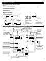
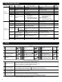
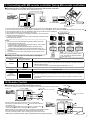
SYSTEM CONTROL Interface
MAC-333IF-E
Model
[FOR INSTALLER]
INSTALLATION MANUAL
English
Contents
1. Safety Instructions............................................................... 2
2. Before Installation................................................................ 3
3. Function and electric wiring of interface each part.............. 3
4. Dip Switch Details............................................................... 4
5. Parts.................................................................................... 4
6. Connecting the SYSTEM CONTROL Interface to a room
air conditioner...................................................................... 5
7. Connecting the SYSTEM CONTROL Interface with each
system (For details on each system, see the relevant
instruction manual.)............................................................. 5
8. Connecting with M-NET system.......................................... 6
9. Connecting with MA remote controller (Using MA remote
controller)............................................................................ 7
10. Remote Control................................................................. 7
11. Setting Signal Output........................................................ 8
12. Turn on/off with power....................................................... 9
13. Interface status monitor..................................................... 9
14. Mounting the SYSTEM CONTROL Interface Unit........... 10
15. Notes Regarding Use...................................................... 10
16. Specifications.................................................................. 10
About SYSTEM CONTROL Interface
● Some room air conditioners cannot be attached to the interface.
Please make sure the room air conditioner can be used before attempting to attach it.
1. Safety Instructions
●Read all Safety Instructions before using this device.
●This manual contains important safety information.
Be sure to comply with the instructions.
●After installing the interface, provide this Installation Manual
to the user. Instruct users to store their room air conditioner
Instruction Manual and Warranty in a safe location.
WARNING
(Improper handling may have serious consequences, including serious injury or death.)
■Users should not install the Interface on their own.
Improper installation may result in fire, electric shock, or
damage/water leaks if the Interface unit falls. Consult the
dealer from whom you purchased the unit or professional
installer.
■The Interface should be securely installed in
accordance with the enclosed Installation Instructions.
Improper installation may result in fire, electric shock, or
damage if the Interface unit falls.
■The unit should be mounted in a location that can
support its weight.
If installed in an area that cannot support the unit, the
Interface unit could fall and cause damage.
■Mount so wiring external force and stress are not
transmitted at the terminal connection.
Improper connection and mounting may result in breaking,
heat generation, smoke generation, or fire.
■Securely attach the cover to the Interface unit.
If the cover of the Interface unit is not securely attached,
dust or water penetration could occur, resulting in a fire or
electric shock.
■The Interface unit should not be connected to the AC
power cable.
Connecting greater than the rated voltage may result in
damage or fire.
■Mitsubishi components or other designated
components must be used for installation.
Improper component may result in fire, electric shock, or
damage/water leaks if the Interface unit falls.
■Electric work must be perform by authorized personnel
according to the local regulations and the instructions
detailed in the installation manual.
Inadequate circuit capacity or improper installation may result
in electric shock or fire.
■This appliance is not intended for use by persons
(including children) with reduced physical, sensory
or mental capabilities, or lack of experience and
knowledge, unless they have been given supervision
or instruction concerning use of the appliance by a
person responsible for their safety.
■Children should be supervised to ensure that they do not
play with the appliances.
■This device complies with part 15 of the FCC Rules. Operation
is subject to the following two conditions:
(1) This device may not cause harmful interference, and (2)
this device must accept any interference received, including
interference that may cause undesired operation.
■This Class B digital apparatus complies with Canadian
ICES-003.
Cet appareil numérique de la classe B est conforme à la
norme NMB-003 du Canada.
CAUTION
(Improper handling may have consequences, including injury or damage to house.)
■To prevent damage from static electricity, touch a
Direct sunlight and hot or low temperature environments
nearby metal body to discharge static electricity
may cause the Interface unit to deform or breakdown.
before touching the Interface unit.
■Do not use in special environments.
Static electricity from the human body may damage the
Use in places with much oil (including machine oil),
Interface unit.
steam, or sulfuric gas may lead to severe decrease in
■Do not install the Interface unit a place with much
functionality and damage to parts.
steam, such as bathroom.
■Turn off power supply of connected equipment when
Avoid places where water is splashed or where
performing construction or wiring work.
condensation forms on walls. Installing in such places can Failure to turn off the power supply of the connected
cause electric shock or breakdown.
equipment may lead to malfunction or breakdown of the
■Do not install the Interface unit in places with direct
Interface unit or connected equipment.
sunlight or where the ambient temperature is 40ºC or
more or is 0ºC or less.
2. Before Installation
How to Use the SYSTEM CONTROL Interface.
■Functions
Connecting with M-NET system (Fig. 2-1)
The room air conditioner can be managed centralized or individually by the system controller using M-NET communications control.
Use as wired remote controller (Fig. 2-2)
You can use the MA remote controller as a wired remote controller.
Remote control (Fig. 2-3)
You can turn on and off an air conditioner from a remote location by connecting the ON/OFF contact point.
Status indicator output (Fig. 2-4)
Operation on/off and error/ok status can be output at the same time.
■Sample System Configuration
8
2
1
5
Fig. 2-1
7
1 System controller, etc
2 SYSTEM CONTROL
Interface
3 Indoor Unit
4 MA remote controller
5 Contract point
4
Fig. 2-2
2
2
3
Fig. 2-4
3
2
5
9
6
3
3
Fig. 2-3
6 Relay
7 Coil
8 Power supply unit for
M-NET transmission line
9 External power supply
for DC12V
3. Function and electric wiring of interface each part
To use centralized control by
M-NET
To use MA remote controller
Wired remote controller such as MA
remote controller
System controller such as a Webenabled centralized controller
Status of room air
conditioner output
Indoor unit
Relay, etc
DC power
supply (12V)
To CN105
M-Net1
B1 A1
M-Net2
B2 A2
TB580 MA
B
A
TB521
S
TB520
LE581
(Orange)
Function setting switch A
*Refer to section 4 “Dip
Switch Details” for details.
ON
Function setting switch B
*Refer to section 4 “Dip
Switch Details” for details.
ON
12345678
12345678
LE502
TB530
- +
(Gray)
(Sky Blue)
LED for checking communications with connected equipment
*Refer to section 13 “Interface
status monitor” for details.
CN591
(White)
SW500
Commercially available
Card key, Coin timer, etc.
SW502
CN560
(Orange)(Red)
LE501
TB571
R2 R1 C
(White)
0
0
SW501
SW510
M-Net
0
To input control signal
and control room air
conditioner remotely
MA
SW580
LED for checking communications with connected equipment
*Refer to section 13 “Interface
status monitor” for details.
M-NET address setting switch
*Refer to section 8 “Connecting
with M-NET system” for details.
Refrigerant address setting switch
*Refer to section 9 “Connecting with
MA remote controller” for details.
4. Dip Switch Details
Functions
Function
setting SW A
Functions
SW500-1
SW500-2
— (Set to OFF)
Not available
—
Available
SW500-3
Not in use
Turn on/off with power
Room temperature
detector
Indoor unit
MA remote controller
9
SW500-4
SW500-5
SW500-6
Not in use
Not in use
Not in use
— (Set to OFF)
— (Set to OFF)
— (Set to OFF)
LE501:Confirmation of communications
with indoor unit
LE502:Confirmation of
communications with M-NET
LE581:Confirmation of supplying
power to MA remote controller
—
—
—
—
—
—
ON
LE501:Confirmation of
communications with MA
remote controller
LE502:Extinguished
LE581:Confirmation of supplying
power to MA remote controller
—
SW500-7
Interface status display
switching
SW500-8
Not in use
— (Set to OFF)
SW502-1
Output switching
SW502-2
Input mode
DC12V output when stopped or
DC12V output when running or in error operating normally
Level contact
Pulse contact
SW502-3
Function
setting SW B
OFF (Factory setting)
Refer to
section
—
12
SW No.
SW502-4
SW502-5
SW502-6
SW502-7
SW502-8
Setting of range of
prohibited operations by M-NET system controller
ON/OFF operation allowed
contact point
Running or operating the machine is
Input mode when
prohibited by short circuiting the level
level contact
Input
contact
switching Input mode when
ON/OFF is inverted by pressing pulse
pulse contact
contact
Behavior when
State before prohibition of operation by
operation by contact
contact point
point is prohibited
Behavior when
prohibition of operation State before canceling prohibition of
by contact point is
operation by contact point
canceled
— (Set to OFF)
Not in use
— (Set to OFF)
Not in use
M-NET system controller ON/OFF
operation prohibited
Running or operating machine is
prohibited by level contact opening
13
—
11
10
10
10
ON or OFF no matter how many times
pulse contact is pressed
Air conditioner running stop
10
Running air conditioner
10
—
—
—
—
5. Parts
Accessory
Interface unit
[with connecting cable (5-core)]
1
Mounting cord clamps
(medium)
4
Fasteners (for joining the
wires)
5
Screws for mounting
3.5×12
2
Mounting cord clamps
(large)
3
Lead wires (3-core)
1
Cushioning material
(with adhesive)
1
Screws for mounting 3.5 × 12 ,
and (Use when attaching
the clamps to the interface unit)
4
Screws for mounting
4 × 10 (Use when fixing
near the room air conditioner)
1
Mounting cord clamps (small)
2
Cable ties
9
Screws for mounting
4 x 16 (Use when joining
room air conditioner parts)
1
Item to be Prepare at the Installation Site
M-NET communication
cable
Remote control cable
(for the connecting the
ME Remote Controller)
Remote control cable
(for connecting the MA
Remote Controller)
2-core shield cables CVVS/CPEVS,1.25mm2 or more.*
• When cross-wired by same terminal box, 1.25mm2 is used.
CPEVS: PE insulated PVC jacketed shielded communication cable
CVVS: PVC insulated PVC jacketed shielded control cable
PE: Polyethylene PVC: Polyvinyl chloride
2-core shield cables CVVS/CPEVS*
• When the distance from the interface unit
is less than 10m: 0.3mm2 or more.*
• When the distance from the interface unit is not less than 10m: 1.25mm2 or more.*
2-core sheath cable 0.3mm2 to 1.25mm2*
Sheath cable 0.3mm2 or more.*
• When remote control: The extension cable of Lead cable
• When status signal output: The cable for relay connection, or cable for DC power
Related parts sold separately Prepare the necessary number of parts sold separately as needed for your system.
* Please use cable with supplementary insulation.
Signal cable (also used
as extension cable)
6. Connecting the SYSTEM CONTROL Interface to a room air conditioner
● Connect the interface unit
unit .
Room air conditioner
Indoor
controller
board
and the indoor control board of a room air conditioner using the connecting cable (5-core) that comes with the interface
Thin part of the connecting cable
Make sure to wire and shield the cable
so that the customer does not contact it.
CN105
(CN92)
Connect the connecting cable (5-core) that comes with
the interface unit ❶ to the connector CN105 on the indoor
control board of a room air conditioner.
Interface unit ❶
Thick part of the
connecting cable
Connecting
connector
WARNING
Securely fix the
connecting cable in
the designated place.
Failure to do so may
cause an electric shock,
fire, or malfunction.
● The connecting cable (5-core) connected to a room air conditioner should be wired according to the room air conditioner installation manual.
Notes
• Extending or shortening the connecting cable (5-core) that comes out of the interface unit ❶
cause it to malfunction. Also, keep the connecting cable (5-core) as far as possible away from the
electrical wires and ground wire. Do not bundle them together.
• To prevent the board from being damaged by static electricity, always remove static electricity
before starting work.
7. Connecting the SYSTEM CONTROL Interface with each system
(For details on each system, see the relevant instruction manual.)
● Screw the mounting cord clamp ❹ ~ ❻ according to the thickness of the ● The connecting cable (5-core) connected to a room air conditioner
connecting cable used for each system. Fasten the cable tie ❽ as shown should be mounted at the room air conditioner or its vicinity.
in the figure to prevent undesirable movement of the connecting cable.
If the screw for the cable mount of the room air conditioner cannot be
Screw ❼
Mounting cord clamps ❹ ~ ❻
used, replace with the screw for mounting 12 .
Screw
Connecting cable
for each system
Cable tie ❽
Mounting
cord clamp ❺
Notes
• If the connecting cable is not securely mounted, the connector may come off, break, or
malfunction.
• The dip switch (SW500, SW502) and the rotary switch (SW501, SW510, SW580) on the
interface unit ❶ do not operate if they are not set correctly.
11
Cable mount
Screw
12
Connecting cable
(5-core)
Mounting
cord clamp ❺
●Conduct the settings of the interface unit ❶ dip switch (SW500, SW502) and rotary switch (SW501, SW510, SW580) before turning on the power.
8. Connecting with M-NET system
■ Connecting the SYSTEM CONTROL Interface to M-NET cable
The room air conditioner can be managed centralized or individually by the system controller using M-NET communications control.
Indoor unit
TB520
B A
S
B2 A2 B1 A1
S
B A
System controller,
etc.
Power supply unit
TB521
S
SW580
0
SW501 SW510
0
CN560
0
Interface unit ❶
●To connect with the system controller and ME remote controller, connect the M-NET communication cable A or ME remote control cable B with
TB520. (It is unpolarized.) Connect 2 core communication cable with A1/B1 or A2/B2. (There will be no problems with connecting to either one.)
●Cross the shield portion of each connecting cable using the S terminal only when cross wiring the connecting wire A .
●After wiring is complete, mount securely with any of mounting cord clamp ❹ to ❻ , and fix with cable tie ❽ as shown in the figure.
When the communication
cable A cross-wired.
When the communication cable A are cross
wired and ME remote controller is used
A1 B1 A2 B2
S
A1 B1 A2 B2
S
Note
When cross-wired by the
same terminal box, a 1.25mm2
line is used.
Shield
Shield wire
ME remote controller cable B
Communication cable A
(M-NET cable)
Communication cable A
(M-NET cable)
Communication cable A
(M-NET cable)
ME remote controller
When the communication
cable A is not cross wired.
When the communication
cable A are cross wired.
Screw for mounting ❼
Screw for mounting ❼
Cable tie ❽
Mounting cord
clamp (Large) ❻
or (Medium) ❺
Screw for mounting ❼
Cable tie ❽
Cable tie ❽
Mounting cord
clamp (Large) ❻
or (Medium) ❺
Screw for
mounting ❼
Mounting cord
clamp (Large) ❻
or (Medium) ❺
Cut with nippers at the notches. Make sure the cut surface is free
of any burr so that the connecting cable does not get damaged.
Cable tie ❽
* To prevent penetration by condensation, insects, etc., seal the opening well with putty.
Notes
• Electrical work should be performed in accordance with the Technical Standards Regarding Electrical Equipment and the Interior Wiring Standards.
• Connecting wires and remote control cables should be located as far away from other electrical wiring as possible. Placing them too closely
together could cause a malfunction.
• To connect with the M-NET system and MA remote controller, connection is limited to only one unit of the MA remote controller.
• Do not put in the same group as City Multi or P series.
• Test run cannot be conducted from the ME remote controller or the system controller.
■ Setting when M-NET is connected
Address
SW No.
M-NET address
SW510
SW501
10s position 1s position
1
0
SW510
SW501
Comments
SW510 sets the 10s position of the address and SW501 sets the 1s position of the address.
(Address setting can be set from 01 ~ 50.)
For example, to set a unit to the address 25, set SW510 to “2” and SW501 to “5.”
* The figure to the left is for address 1.
Refrigerant address
SW580
When the MA remote controller is not used, set the refrigerant address (SW580) to “1.”
SW580
9. Connecting with MA remote controller (Using MA remote controller)
■ Connecting the SYSTEM CONTROL Interface to MA remote controller
A room air conditioner can be operated with the wired remote control.
MA remote controller cable C
Indoor unit
Screw for
mounting ❼
BA
SW500
TB580
MA remote controller
SW580
CN560
MA remote controller
0
Mounting cord
clamp (Large) ❻
or (Medium) ❺
MA remote
controller cable C Cable tie ❽
MA remote controller
or Interface unit
Interface unit ❶
● To connect with the MA remote controller, connect the MA remote control cable C with TB580. (It is unpolarized.)
● When more than one unit of room air conditioner is operated in a group, make a cross wire connection at TB580 with the MA remote control cable
● The MA remote controller can carry out simultaneous control of up to 16 sets of room air conditioners.
Group control
● Up to two MA controllers can be connected in one group.
● Wiring length from the interface at the refrigerant address “0” to the MA remote
Outdoor unit
Outdoor unit
Multi outdoor unit
controller should be less than 10m.
● To operate the room air conditioner in a group, make the total length of wiring for the MA
remote controller less than 50m.
Notes
• Be sure to set the “Auto Heating/Cooling Display Setting” of the MA
remote controller OFF before use.
* For details on the “Auto Heating/Cooling Display Setting”, refer to the MA
remote controller instruction manual.
* When the “Auto Heating/Cooling Display Setting” is ON, the remote
controller display may differ from the actual operating status of the unit.
• A test run cannot be initiated using the test run switch on the MA remote
controller.
• Timer operation is set up from either wireless remote controller or MA
remote controller.
■ Setting when MA remote controller is connected
SW580
Indoor unit
Interface unit ❶
(Refrigerant
address“0”)
Refrigerant address
Indoor unit
Interface unit ❶
(Refrigerant
address“1”)
Indoor unit
Interface unit ❶
(Refrigerant
address“2”)
Interface unit ❶
(Refrigerant
address“3”)
Note
Even when connecting multiple outdoor
units, set a different refrigerant address
for each indoor unit.
MA remote
controller
●Setup of an refrigerant address
SW No.
Indoor unit
C.
Comments
Address can be set from 0 to 15 • Set the refrigerant address of the unit that supplies electric power to the MA remote controller to “0.”
• When carrying out group operation of two of more room air conditioners, set different refrigerant
addresses within the group.
*A to F of the rotary switch correspond to refrigerant addresses 10 to 15.
●Setup of Room temperature detector position
Functions
Room
temperature
detector position
SW No.
Operating details
SW500-3
ON
ON
1
2
3
4
5
6
7
8
OFF
OFF
• Temperature detected by suction temperature sensor of the unit is made to be room temperature.
ON
• Temperature detected by temperature sensor of the remote controller is made to be room
temperature.
10. Remote Control
■ Connecting the SYSTEM CONTROL Interface
Signal cable D
You can turn room air conditioner on/off or prohibit/allow manual operations with the ON/OFF switch.
Interface unit ❶
E SW1, SW2
Indoor unit
CN560
(Usable at DC12V, 0.5 to 2.0mA)
10
SW1
SW2
Cable tie ❽
Lead wire 10
D
Indoor unit
●Connect CN591 with SW1 and SW2 as shown in figure above.
●Connect the supplied lead wire (3-core) 10 to the connector CN591 on
the interface unit.
●Connect the supplied lead wire (3-core) 10 to the connecting cable D
in the interface ❶ as shown in the figure on the right side.
●Wiring length from the interface to the SW 1 and SW 2 should be less than 50m.
●Procure and wire locally the remote control part including the switches.
●For each connection pattern, refer to “Setting when using remote control.”
*When using a Card key/Coin timer, make connections shown in the figure to the right.
Connect in the interface
unit ❶
Card key coin timer connection
Interface unit ❶
CN591
3 2 1
SW502
Orange
Red
Brown
SW502
Orange
Red
Brown
CN591
3 2 1
10
Insulate
CN560
E
SW2
D
(Card key/coin timer)
■ Setting when using remote control (Select one between No.1 through 4 and set.)
*Set No.1, No.5, and No.6 when using the card key/coin timer.
No.
Functions
ON/OFF
Manual operation
1
prohibited/allowed
(Level Contact)
ON/OFF
Manual operation
2
prohibited/allowed
(Pulse Contact)
ON/OFF
Remote operation/
Manual operation
(Level Contact)
3
ON, OFF
(Pulse Contact)
4
How to use
SW No.
SW502-2~4
1
Red
2
Orange
3
CN591
ON
1
2
3
4
5
6
7
8
SW502-2~4
1
ON
1
2
3
4
5
6
7
SW502-2~4
2
3
4
5
1
6
7
8
1
3
4
5
6
7
Brown
Brown
Red
2
Orange
3
CN591
ON
2
Red
Red
2
Orange
3
CN591
SW502-2~4
1
Brown
2
Orange
3
CN591
8
ON
1
Brown
8
Operating details
SW1:
ON/OFF
SW2:
Manual operation
prohibited/allowed
•Unit is turned on when SW1 has a short-circuit, and off when open.
(Regardless of the SW1 operation condition, the latest operation is prioritized.)
•When SW2 has a short-circuit, manual operation is prohibited,* and when open, manual operation is allowed.
•When SW502-4 is turned on, the opening and short-circuiting of
SW1 and SW2 result in their operating in the opposite manner.
*When manual operation is prohibited, ON/OFF operation of the wireless
remote controller, the MA remote controller, and the ME remote controller is
prohibited. (Operation from SW1 and M-NET system controller is possible.)
SW1:
ON/OFF
SW2:
Manual operation
prohibited/allowed
•Every time SW1 is pressed, ON/OFF is switched over.
(Regardless of the SW1 operation condition, the latest operation is prioritized.)
•Every time SW2 is pressed, the manual operation prohibited*/the manual operation allowed is switched over.
*When the manual operation is prohibited, ON/OFF operation of the wireless
remote controller, the MA remote controller, and the ME remote controller is
prohibited. (Operation from SW1 and M-NET system controller is possible.)
SW1:
ON/OFF
SW2:
Remote operation/
Manual operation
•Unit is turned on when SW1 has a short-circuit, and off when open.
•When SW2 has a short-circuit, only SW1 is enabled (remote
operation)*, when open, only SW1 is disabled (manual operation).
•When SW502-4 is turned on, the opening and short-circuiting of
SW1 and SW2 result in their operating in the opposite manner.
*In remote operation, ON/OFF operation from the wireless remote
controller, the MA remote controller, the ME remote controller, and the
M-NET system controller cannot be used.
SW1:
ON
SW2:
OFF
•Unit is turned on no matter how many times SW1 is pressed.
•Unit is turned off no matter how many times SW2 is pressed.
And regardless of the SW1, SW2 operation condition, the latest
operation is prioritized.
•ON/OFF operation from the wireless remote controller, the ME remote controller, the MA remote controller, and the M-NET system controller is enabled.
■ Setting operation (Valid only for No.1 and No.2. The following 2 functions can be used at the same time.)
No.
Functions
SW No.
Behavior when
5 operation is
prohibited.
How to use
SW502-5
ON
ON
1
2
3
4
5
6
7
8
OFF
Behavior when
prohibition of
6
operation is
canceled.
SW502-6
ON
ON
1
2
3
4
5
6
7
8
OFF
Operating details
Operational status of room
air conditioner when
manual operation is
prohibited can be set.
OFF
•When manual operation is prohibited by SW2, operational status is
maintained as that before manual operation is prohibited.
ON
•When manual operation is prohibited by SW2, the room air conditioner turns off.
Operational status of room
air conditioner when
prohibition of manual
operation is canceled can
be set.
OFF
•When prohibition of manual operation is canceled by SW2, operational status is maintained as that before cancelation.
ON
•When prohibition of manual operation is canceled by SW2, the room air conditioner turns on.
11. Setting Signal Output
■ Connecting the SYSTEM CONTROL Interface
External relays can be turned on/off synchronized with room air conditioner being on/off or in error/operating normally.
D
R2
Interface unit
Indoor unit
R2 R1 C
–
TB571 TB530
(Gray) (Sky
Blue)
SW502
+
Relay 2
DC 12V
power
+ supply
E
2
Relay 1, 2:
(Coil rating of DC 12V, 75mA
or less.) Please use relays with
reinforced insulation.
Relay 1
E
R1
–
CN560
Driver
DC power supply: DC 12V (+10%, -0%) 5W or more. Please use
power supply with double insulation or reinforced insulation.
Please use the cable of 0.5mm or more.
The cable must fit into TB530 and meet DC12V power supply.
Terminal
Do not insert more than one
connecting cable into each
terminal of TB571 and TB530.
Notes
• Connecting terminal TB530 for power supply is polarized, so confirm proper polarity of the terminals before connecting.
• Do not connect DC12V from the DC power supply to TB571.
• Confirm polarity when using a diode built-in relay. C of TB571 is electropositive potential + , and R1 and R2 are negative potential
● For TB571 and TB530, insert wiring after inserting the flathead screwdriver into the terminal.
● Appropriate electric wire for TB571 and TB530 is as follows. Stranded wire: 0.3mm2 to 1.25mm2 Solid wire: ø0.4mm to ø1.2mm
● Peeling dimension of the electric wire for TB571 and TB530 is 7mm to 10mm.
● Wiring length from the interface to Relay 1 and Relay 2 should be less than 50m.
.
■ Setting when using Status Signal Output
Functions
Status signal
output
ON
ON
1
Operating details
SW No.
SW502-1
2
3
OFF
4
5
6
7
8
OFF
• Relay 1 is on when room air conditioner is on, and off when room air conditioner is off.
• Relay 2 is on when room air conditioner is in error, and off when room air conditioner is operating normally.
ON
• Relay 1 and 2 behavior are opposite of those above.
12. Turn on/off with power
The room air conditioner turns on when power is supplied.
●When using for the first time, set to the operational status of your choice with the remote controller and leave the power off for 1 minute.
*When not used for a long period of time, you should set to the operational status of your choice again with the remote controller.
Interface unit ❶
Indoor unit
Notes
● The turn on/off with power function cannot be used when
connected to multiple outdoor units.
● When starting two or more room air conditioners by using
the turn on/off with power function, make the system so they
do not recover simultaneously. (To avoid inrush current, start
sequentially.)
SW500
CN560
Setting when using Turn on/off with power
Functions
SW No.
Operating details
OFF
•After the power is supplied, the room air conditioner resumes working in the previous running condition. When AUTO RESTART FUNCTION is not set to the room air conditioner, it
remains off.
ON
•The room air conditioner turns on when power is supplied.
SW500-2
Turn on/off with
power
ON
ON
1
2
3
4
5
6
7
8
OFF
13. Interface status monitor
You can check the status of the interface unit by the LED
lamp on the interface unit board.
Indoor unit
Interface unit ❶
SW500
LE501
LE502
LE581
CN560
●Use the table below to check communications. If communications cannot be carried out normally, check that the relevant communications line is
not disconnected from the connector or terminal box.
Functions
Operating details
SW No.
SW500-7
Interface status
monitor
ON
ON
1
2
3
4
5
6
7
8
OFF
OFF
●LE501 (Orange): When blinking at an interval of about 1 second, the Interface unit is
communicating normally with the room air conditioner. When the lamp
is off, the Interface unit is not communicating normally with the room air
conditioner.
●LE502 (Red): When blinking at an interval of about 1 minute, the Interface unit is
communicating normally with the M-NET controller. When the lamp is off, the
Interface unit is not communicating normally with the M-NET controller.
ON
●LE501 (Orange): When blinking at an interval of about 10 second, the Interface unit is
communicating normally with the MA remote controller. When the lamp is
off, the Interface unit is not communicating normally with the MA remote
controller.
●LE502 (Red): Extinguished
*LE581 (Orange) displays the following status irrespective whether SW500-7 is on or off.
●When lit, power is supplied to the MA remote controller from the Interface unit ❶ . When
extinguished, power is not supplied.
14. Mounting the SYSTEM CONTROL Interface Unit
Notes
•The Interface unit should be placed in a location where the connecting cable (5-core) from the interface unit can reach an indoor unit.
•The device will not function properly the connecting cable is extended, so the connecting cable (5-core) should no be extended.
•Mount the interface unit securely to a pillar or wall using 2 or more screws.
Attach the connecting cable (5-core) of the interface unit ❶ here. Store extra connecting cable (5-core) in the ductwork space behind
the air conditioner.
If there is any slack in the connecting cable (5-core), use a fastener ❾ to keep it in place.
n When mounting the interface unit inside a ceiling
n When Mounting Directly to a Wall
Mount the interface unit ❶ case to the
wall using the mounting screws ❷ .
Interface unit ❶ mounting
screws
When mounting the interface unit ❶ inside a ceiling or
wall, install an access door to facilitate maintenance.
Interface unit ❶
Cushioning
material ❸ .
Screw for mounting ❷ .
40 mm
or more
When the interface unit ❶ is mounted above
an indoor unit, it should be positioned 40 mm
or more away from the unit to ensure that
ceiling grills can be removed.
*When mounting the interface unit ❶ using a cushioning
material ❸ , be sure to mount it in a location where it
will not fall.
15. Notes Regarding Use
The following control information should be thoroughly explained and provided to the users of this device. (Please provide these instructions to the
user once the installation is complete.)
This Interface unit ❶ operates room air conditioners using the controls of a City-Multi or P series, but there are several limitations imposed as a result
of the functional differences between room air conditioners and packaged air conditioners.
1. When operating the system using a System Controller, MA Remote Controller, or ME Remote Controller these operations will not appear on the
display of the wireless remote controller.
2. When original dehumidification mode is set with the remote controller attached to the room air conditioner, “Dry” is displayed because there is no
mode corresponding to dehumidification on the MA remote controller, ME remote controller, and the system controller.
3. Because the temperature range of the room air conditioners is broader than a System Controller, ME Remote Controller, or ME Remote Controller,
when the room air conditioners is set to lower than 17°C or higher than 30°C, the temperature display on the a System Controller, MA Remote
Controller, or ME Remote Controller will show the minimum or maximum temperature that can be set. (For example, even if the room air conditioner
is set to cool a room to 16°C, the display on a System Controller, MA Remote controller, or ME Remote Controller may read “17°C”).
4. Timer operations should be set using only the remote controller that came with the room air conditioners or the a System Controller, MA Remote
Controller, or ME Remote Controller. If both are used to set the timer to the same time, the timer will not function properly.
5. When “Manual operation prohibited” (ON/OFF, setting temperature, operation mode) is set with the system controller, the corresponding operation
by the remote controller attached to the room air conditioner is not accepted, but allowed operation is reflected. A beep sounds during operation to
confirm reception.
6. A part of functions including the operation of horizontal air blow direction cannot be used from the ME remote controller, the system controller, and
the MA remote controller.
16. Specifications
Indoor unit side
Power supply unit side
10
Input voltage
Power consumption
Input current
Input voltage
Power consumption
Input current
12V
1.8W
0.15A
12V
4.8W
0.4A
This product is designed and intended for use in the residential,
commercial and light-industrial environment.
The product at hand is based on
the following EU regulations:
• Low Voltage Directive 2006/95/EC
• Electromagnetic Compatibility Directive
2004/108/EC
HEAD OFFICE: TOKYO BLDG., 2-7-3, MARUNOUCHI, CHIYODA-KU, TOKYO 100-8310, JAPAN
AUTHORIZED REPRESENTATIVE IN EU:
MITSUBISHI ELECTRIC EUROPE B.V.
HARMAN HOUSE, 1 GEORGE STREET, UXBRIDGE, MIDDLESEX UB8 1QQ, U.K.
JG79A570H01
Printed in Japan