1
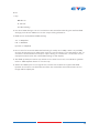
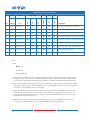
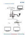
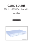
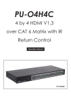
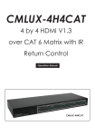
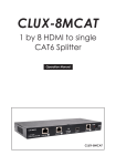
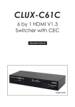
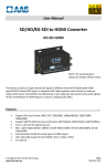
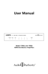
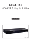
CLUX-H2SDI HDMI to 3G SDI Dual-Output Converter Operation Manual DISCLAIMERS The information in this manual has been carefully checked and is believed to be accurate. Cypress Technology assumes no responsibility for any infringements of patents or other rights of third parties which may result from its use. Cypress Technology assumes no responsibility for any inaccuracies that may be contained in this document. Cypress also makes no commitment to update or to keep current the information contained in this document. Cypress Technology reserves the right to make improvements to this document and/or product at any time and without notice. COPYRIGHT NOTICE No part of this document may be reproduced, transmitted, transcribed, stored in a retrieval system, or any of its part translated into any language or computer file, in any form or by any means— electronic, mechanical, magnetic, optical, chemical, manual, or otherwise—without express written permission and consent from Cypress Technology. © Copyright 2011 by Cypress Technology. All Rights Reserved. Version 1.1 August 2011 TRADEMARK ACKNOWLEDGMENTS All products or service names mentioned in this document may be trademarks of the companies with which they are associated. SAFETY PRECAUTIONS Please read all instructions before attempting to unpack, install or operate this equipment and before connecting the power supply. Please keep the following in mind as you unpack and install this equipment: • Always follow basic safety precautions to reduce the risk of fire, electrical shock and injury to persons. • To prevent fire or shock hazard, do not expose the unit to rain, moisture or install this product near water. • Never spill liquid of any kind on or into this product. • Never push an object of any kind into this product through any openings or empty slots in the unit, as you may damage parts inside the unit. • Do not attach the power supply cabling to building surfaces. • Use only the supplied power supply unit (PSU). Do not use the PSU if it is damaged. • Do not allow anything to rest on the power cabling or allow any weight to be placed upon it or any person walk on it. • To protect the unit from overheating, do not block any vents or openings in the unit housing that provide ventilation and allow for sufficient space for air to circulate around the unit. REVISION HISTORY VERSION NO. DATE DD/MM/YY SUMMARY OF CHANGE VR0 04/01/11 Preliminary release VR1 04/07/11 Supported timing added VR2 28/09/11 Spec. Position Changed VS3 11/07/12 Updated format/diagrams/SDI standards VS4 13/07/12 First release VR5 24/07/12 SDI supports [email protected] CONTENTS 1. Introduction�������������������������������������������� 1 2. Applications������������������������������������������� 1 3. Package Contents�������������������������������� 1 4. System Requirements���������������������������� 1 5. Features�������������������������������������������������� 2 6. Operation Controls and Functions������� 3 6.1 Front Panel���������������������������������������3 6.2 Rear Panel�����������������������������������������4 6.3 EDID Update Procedure������������������5 6.4 LED Signal Chart�������������������������������7 7. Connection Diagram�������������������������� 10 8. Specifications�������������������������������������� 11 9. Acronyms��������������������������������������������� 12 1. INTRODUCTION The HDMI to SDI Converter allows HDMI signals to be shown on two SDI displays while ensuring high bit rates of 2.970 Gbit/s to give you high resolution signal without any loss. For professionals this means that it is now easier to convert your high def HDMI signal with audio to SDI for long distance transmission and display your work on two SDI displays. Also, a 2 CH L/R audio input allows DVI signal with 2CH audio to be converted to SDI in order to be shown on SDI displays. Furthermore, the device has a built-in default EDID and a recordable EDID that guarantee image display compatibility with source equipment. 2. APPLICATIONS • HDMI signal display on SDI display(s) • Extending a HDMI signal over 100m to two SDI displays • DVI signal with audio display on SDI display(s) (DVI to HDMI adaptor cable required) • Cascade HDMI signal over SDI cables 3. PACKAGE CONTENTS • HDMI to 3G SDI Dual-Output converter • 5 V/2.6 A Power Adaptor • Operation Manual 4. SYSTEM REQUIREMENTS • Input HDMI/DVI (with audio signal) source equipment with connection cable(s). • Output SDI display(s) or SDI to HDMI converter(s) with connection cable(s). 1 5. FEATURES • Shows HDMI source on two SDI displays simultaneously • SDI interface operates at bitrates of 2.970 Gbit/s, 2.970/1.001 Gbit/s, 1.485 Gbit/s, 1.485/1.001 Gbit/s and 270 Mb/s • Converts HDMI signal to SDI: 1. 480i/576i to SD-SDI (SMPTE 259M-C, at bitrates of 270 Mbit/s) 2. 720p/1080i to HD-SDI (SMPTE 292M, at bitrates of 1.485 Gbit/s or 1.485/1.001 Gbit/s) 3. 1080p to 3G-SDI (SMPTE 424M/425M-AB, at bitrates of 2.970 Gbit/s and 2.970/1.001 Gbit/s) • Supports HDMI input timings: [email protected], 576i, 720p@50/59.94/60, 1080i@50/59.94/60, [email protected]/24/25/29.97/30/50/59.94/60 • Choose between a selectable EDID and recordable EDID • Integrated audio embedded up to 8 CH PCM 48 kHz for HDMI or 2 CH (external L/R) for DVI audio • Supports SDI output distance up to 100 meters (3G-SDI), 200 meters (HD-SDI), or 300 meters (SD-SDI) Note: 1. Tested with Belden 1694A Cable. Operating distances may vary if used with cables of different specifications. 2. This product does not process HDCP encrypted input signals. There will be no video output when the input signal contains content that is HDCP encrypted. 2 6. OPERATION CONTROLS AND FUNCTIONS 6.1 Front Panel 4 5 7 8 EDID Update 3G HD 3G SDI SD HD EDID 3G EDID 2 Out 1 CLUX-H2SDI HDMI to 3G SDI HDMI/DVI Video Lock 1 3 6 Out 2 9 1 EDID Switch: Use this switch to select between the built-in or to update the EDID settings. Default EDID settings as shown below: 3G EDIDNative Mode 1080p@60 HD EDIDNative Mode 1080i@60 EDID updateNative Mode 720p@60 2 EDID Update button: Only use this function when the image has not displayed correctly after trying to switch the EDID Update/ HD/3G mode with the EDID switch (refer to Section 6.3 for update procedure). 3 HDMI/DVI LED: The LED will illuminate green only when the input source is HDMI. It will not illuminate when the input is DVI. 4 Video Lock LED: The LED will illuminate yellow when the HDMI input is receiving and locking a signal. 5 EDID Update LED: The LED will illuminate red when the EDID settings are being updated (refer to Section 6.4 LED Signal Chart). 6 SD LED: The LED will illuminate green when the HDMI input signal is 480i/576i. 7 3G LED: The LED will illuminate red when the HDMI input signal is 1080p@50/60. 8 HD LED: The LED will illuminate yellow when the input HDMI input signal is 1080p@24/25/30, 1080i@50/60 or 720p@50/60. 3 9 3G SDI Out 1 & 2: Connect to up to 2 SDI TVs or monitors for mirrored display or to a SDI to HDMI converter to cascade the SDI signal to multiple displays or devices 6.2 Rear Panel Audio In HDMI In Power DC 5V Audio SW HDMI 1 R/L 2 R L 3 4 5 1 HDMI In: Connect to the HDMI source equipment such as DVD or Blu-ray player or it can also be connected to a DVI source (with DVI to HDMI Adaptor cable). 2 Audio Switch: Use this switch to select between HDMI audio or an external analogue stereo source (R/L RCA jack). 3 Audio In R/L:Connect to an audio source such as a DVD or Blu-ray player with R/L RCA jack output or an alternate audio source such as a PC/Notebook. Can be used to provide audio for a DVI input. 4 Power LED: The LED will illuminate when the device is connected to a power supply. 5 DC 5V: Plug the 5 V DC power supply into the Converter and connect the adaptor to an AC outlet. 4 6.3 EDID Update Procedure Please follow this procedure if there is no image displayed or it is displayed incorrectly. A. Please ensure that the display output settings of the source input device (such as a Blu-ray player or HD Camcorder) is set to “Automatic”. If the source image is displayed correctly no further action is necessary but if not to step B. DVD Player HDMI Converter SDI SDI Monitor B. Connect the HDMI source directly (without connecting to the Converter) to a HDMI monitor or TV to see if the image is displayed correctly. Ensure that the source's output timing supports SDI or the Converter's timing. If it is supported, go to step C. If not, please try a different monitor or TV and adjust the timing until the image is displayed correctly. Adjust to correct SDI Timing DVD Player (HDMI Cable) HDMI TV/Monitor C. Connect the HDMI monitor or TV to the input port of the Converter and then set the EDID switch to the 'EDID update' position. Press and hold the EDID update button consistantly until the Video Lock LED illuminates. This will allow the Converter to replace the default EDID settings with the monitor/TV’s EDID settings. Converter 5 1. Move the EDID switch to EDID update position 2. Press and hold the EDID update button (HDMI Cable) HDMI TV/Monitor D. Finally, connect the HDMI source to the HDMI input of the Converter and connect the output to a SDI monitor which should now be correctly displaying the image. DVD Player HDMI Converter SDI SDI Monitor 6 6.4 LED Signal Chart System Operation LED Signal Status ● ● ● Input timing is 3G, HDMI mode ● ● Input timing is HD, HDMI mode ● ● Input timing is SD, HDMI mode ● ● ● ● Input timing no support , HDMI mode ● ● ● ● Input timing is 3G, DVI mode ● ● ● Input timing is HD, DVI mode ● ● ● Input timing is SD, DVI mode ● ● ● ● ● Input timing no support , DVI mode Input timing is 3G, HDMI mode No. Switch key 3G /DVI HDMI /Lock Video Update EDID SD Signal LED HD EDID 1 3G Not Pressed 2 3G Not Pressed ● 3 3G Not Pressed ● 4 3G Not Pressed 5 3G Not Pressed 6 3G Not Pressed ● 7 3G Not Pressed ● 8 3G Not Pressed Description 9 HD Not Pressed ● ● ● 10 HD Not Pressed ● ● ● Input timing is HD, HDMI mode 11 HD Not Pressed ● ● ● Input timing is SD, HDMI mode 12 HD Not Pressed ● ● ● ● Input timing no support , HDMI mode 13 HD Not Pressed ● ● ● ● Input timing is 3G, DVI mode 14 HD Not Pressed ● ● ● ● Input timing is HD, DVI mode 15 HD Not Pressed ● ● ● ● Input timing is SD, DVI mode 16 HD Not Pressed ● ● ● ● ● Input timing no support , DVI mode 17 Update Not Pressed ● ● ● Input timing is 3G, HDMI mode 18 Update Not Pressed ● ● ● Input timing is HD, HDMI mode 19 Update Not Pressed ● ● ● Input timing is SD, HDMI mode 20 Update Not Pressed ● ● ● ● Input timing no support , HDMI mode 21 Update Not Pressed ● ● ● ● Input timing is 3G, DVI mode 22 Update Not Pressed ● ● ● ● Input timing is HD, DVI mode 23 Update Not Pressed ● ● ● ● Input timing is SD, DVI mode 24 Update Not Pressed ● ● ● ● ● Input timing no support , DVI mode 25 Update Not Pressed ● ● ● ● ● ● No input signal or No connect 26 3G Not Pressed ● ● ● ● Input with HDCP Encryption 27 HD Not Pressed ● ● ● ● Input with HDCP Encryption 28 Update Not Pressed ● ● ● ● Input with HDCP Encryption 7 Note 1. Key: "" LED On "●" LED Off "" LED Flashing 2. Not all of HDMI timings can be converted to SDI, therefore selecting the default EDID settings provides the HDMI source with output timing reference. 3. EDID switch mode/Default EDID setting: 3G 1080p@60 HD 1080i@60 Update 720p@60 4. Due to the fact that the HDMI default timing is mainly set to 480p, there is a possibility that the image will not be displayed correctly as that timing is not supported by SDI . To avoid this, set the HDMI source input output setting to “Automatic” so that the source equipment will receive the native EDID settings of the display. 5. The EDID update procedure only needs to be done for Nos. 4,8,12,16,20 & 24. (please refer to “EDID Update button”in section 6.3). 6. When the HDMI input source signal has content that is HDCP encrypted the EDID Update and Video Lock LEDs will both flash, the other LEDs will not illuminate and no image will be displayed. 8 EDID Update LED Confirmation Status Switch key /DVI HDMI Lock Video Update EDID SD Single LED HD EDID 3G EDID 1 Update Pressed On ● ● 3G Native, HDMI mode, Read OK 2 Update Pressed On ● ● HD Native, HDMI mode, Read OK 3 Update Pressed On ● ● SD Native, HDMI mode, Read OK 4 Update Pressed On ● ● ● No support timing, HDMI mode, Read OK 5 Update Pressed On ● ● ● 3G Native, DVI mode, Read OK (Note4) 6 Update Pressed On ● ● ● HD Native, DVI mode, Read OK (Note4) 7 Update Pressed On ● ● ● SD Native, DVI mode, Read OK (Note4) 8 Update Pressed On ● ● ● ● EDID format error (Note5) 9 Update Pressed On ● ● ● ● ● No connection or connection error No. Description Note 1. Key: "" LED On "●" LED Off "" LED Flashing 2. Only when the EDID button is being pressed and hold consistantly will the EDID update progress. When the update is complete the Video Lock LED will illuminate. If the button is not pressed the LED will illuminate according to “System Operation LED Signal Status”. 3. The output HDMI source's output resolution is based on output display monitor/TV’s EDID settings but results may vary with different sources. The EDID update function is designed to resolve compatibility issue such as these. 4. When DVI EDID settings are detected, the system will check if the EDID’s native mode supports SDI timing. If it does, the image will be displayed in the formats in No. 5,6 & 7. If not, the system will automatically copy the default DVI EDID (Native 3G) mode and displayed in the format in No. 5. 5. EDID format errors include: Header error, Checksum error and EDID error. Under this condition the default EDID or the updated EDID will not be updated. 9 7. CONNECTION DIAGRAM Alternative Audio Source DVD or Blu-ray Player HDMI Output Audio In HDMI In Power DC 5V Audio SW HDMI EDID Update 3G HD HD EDID 3G EDID SD HDMI/DVI Video Lock R/L R Out 1 L 3G SDI Out 2 Power Supply CLUX-H2SDI HDMI to 3G SDI SDI Output Video Audio HDMI/ Power Lock Lock DVI SDI Output 3G HD SD Audio Out R HDMI Out L 3GSDI to HDMI CLUX-SDI2HC SDI to HDMI Converter HDMI Output SDI Display HDMI Display 10 8. SPECIFICATIONS SDI Transmission Rates 2.970 Gbps, 2.970/1.001Gbps, 1.485 Gbps, 1.485/1.001Gbps & 270 Mbps Video Bandwidth 225 MHz/6.75Gbps Input 1×HDMI, 1×Stereo Audio (R/L) Output 2×BNC (SD/HD/3G-SDI) HDMI Timing Support [email protected], 576i, 720p@50/59.94/60 1080i@50/59.94/60 [email protected]/24/25/29.97/30/50/59.94/60 SD-SDI: SMPTE 259M-C, 270 Mbit/s HD-SDI: SDI Timing Support SMPTE 292M, 1.485 & 1.485/1.001 Gbit/s 3G-SDI: SMPTE 424M/425M-AB, 2.970 & 2.970/1.001 Gbit/s SDI Cable Distance 3G/HD/3G-SDI up to 100 /200/300 meters with BELDEN 1694A Cable Power Supply 5 V DC/2.6 A (US/EU standards, CE/FCC/UL certified) ESD Protection Human-body Model: ±8 kV (air-gap discharge) ±4 kV (contact discharge) Dimensions 125 mm (W)×115 mm (D)×30 mm (H) Weight 275 g Chassis Material Metal Silkscreen Color Black Operating Temperature 0 °C~40 °C/32 °F~104 °F Storage Temperature −20 °C~60 °C/−4 °F~140 °F Relative Humidity 20~90 % RH (non-condensing) Power Consumption 5.5 W Note: SDI supports SD resolutions of [email protected] and 576i@50 only. If the input source is sending an incompatible resolution, this may cause problems with the image or no image to be displayed. Please ensure that the source device is set to output in a compatible resolution. 11 9. ACRONYMS ACRONYM COMPLETE TERM 3G Bandwidth 2.97Gbps ≈ 3G DVI Digital Visual Interface HDCP High-bandwidth Digital Content Protection HDMI High Definition Multimedia Interface SDI Serial Digital Interface 12 CYPRESS TECHNOLOGY CO., LTD Home page: http://www.cypress.com.tw