1
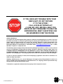
IF YOU HAVE ANY TROUBLE WITH YOUR
NEW LIGHT, DO NOT RETURN
IT TO THE STORE!
CALL ACR ELECTRONICS AT
+1 (954) 981-3333. WE WILL HELP YOU
RESOLVE ANY PROBLEMS YOU MAY BE
EXPERIENCING. MANY QUESTIONS CAN
BE ANSWERED OVER THE PHONE.
LIMITED WARRANTY
This product is warranted against factory defect in material and workmanship for a period of one year
from date of purchase or receipt as a gift. During the warranty period ACR Electronics, Inc. will, at its
option, repair or replace the unit at no cost to you for labor, materials or return transportation. For
further assistance please contact our Technical Service Department at ACR Electronics, Inc., 5757
Ravenswood Road, Fort Lauderdale, FL 33312-6645. Email: [email protected], Fax: +1 (954)
983-5087, Telephone: +1 (954) 981-3333
This warranty does not apply if the product has been damaged by accident or misuse, or as a result of
service or modification by other than the factory. Except as otherwise expressly stated above, the
COMPANY MAKES NO REPRESENTATION OR WARRANTY OF ANY KIND, EXPRESS OR IMPLIED, AS
TO MERCHANTABILITY, FITNESS FOR A PARTICULAR PURPOSE, OR ANY OTHER MATTER WITH
RESPECT TO THIS PRODUCT. The Company shall not be liable for consequential or special damages.
In order to place the warranty in effect, the accompanying registration card must be returned to us
within ten days of purchase.
©2008 by ACR Electronics, Inc., part of Cobham plc. All rights reserved. Reproduction in whole or in
part is permitted only with permission of ACR Electronics, Inc. Ongoing product improvements may
change product specifications without notice.
Trademarks or registered trademarks are the property of their respective owners.
2
Y1-03-0165 Rev. D
TABLE OF CONTENTS
SECTION 1 - INSTALLATION .............................................................................................................. 4
1.1
1.2
Installation Procedures ........................................................................................................................................ 4
Battery Installation ................................................................................................................................................ 4
SECTION 2 - MAINTENANCE ............................................................................................................. 4
2.1
2.2
2.3
2.4
2.5
2.6
Operation ............................................................................................................................................................... 4
Inspection .............................................................................................................................................................. 4
Disassembly .......................................................................................................................................................... 5
Assembly ............................................................................................................................................................... 5
SM-2 Parts List ...................................................................................................................................................... 6
Accessories ........................................................................................................................................................... 6
SECTION 3 - CHARACTERISTICS ...................................................................................................... 8
3.1
3.2
3.3
3.4
3.5
3.6
3.7
3.8
3.9
3.10
3.11
General ................................................................................................................................................................... 8
Purpose .................................................................................................................................................................. 8
Component Ratings .............................................................................................................................................. 8
Operation ............................................................................................................................................................... 8
Construction .......................................................................................................................................................... 8
Lanyard .................................................................................................................................................................. 8
Mounting Bracket .................................................................................................................................................. 8
Dimensional Stability............................................................................................................................................ 8
Stroboscopic Flashing Light ............................................................................................................................... 9
Battery Connection ............................................................................................................................................... 9
Buoyancy ............................................................................................................................................................... 9
PLEASE READ ALL WARNINGS, CAUTIONS
AND NOTES CAREFULLY
CAUTION: In order for the marker light to float properly, the 6 volt battery MUST not weigh
more than 675 grams (1.49 lbs). Exceeding this weight will cause the light to sink.
3
Y1-03-0165 Rev. D
FOREWORD
We design, manufacture and distribute quality products knowing they are used to save lives. Many of our products are
required to be tested and approved by regulatory bodies worldwide. We believe in going beyond those specifications to
insure our products work when needed in real world conditions. With proper care and maintenance your ACR product will
last for years. It is important that you thoroughly read this product support manual to understand the proper care and use
of your ACR product.
ACR is proud to be certified to ISO 9001: 2000, the International Standard for Quality.
Test light buoyancy in shallow water prior to placing in service.
The following battery types are suggested for use in ACR Marker lights:
Suggested Screw Terminal batteries:
BRAND
ANSI/NEDA:
Duracell:
Rayovac:
Eveready:
MODEL NUMBER
915, 915C, 915D, 915AC
M915, PC915
942, 945
510S
Suggested spring terminal batteries (for use with optional battery adapter 9434):
BRAND
ANSI/NEDA:
Duracell:
Eveready:
Energizer:
Rayovac:
Panasonic:
MODEL NUMBER
908, 908C, 908D, 908AC
M908, PC908
509, 1209
EN529, (not 529)
941, 944
W-4FD
NOTE: Check adapter to ensure that screws are tight during regular maintenance.
SECTION 1 - INSTALLATION
1.1
Installation Procedure
The installation procedure requires that the mounting bracket be securely fastened in any convenient location that would
provide immediate access in the event of an emergency.
Suitable length ¼ - 20 stainless screws should be used for mounting the bracket. Screw heads should not protrude inside
the bracket surface.
1.2
Battery Installation
The SM-2 is normally shipped from the factory without a battery. Follow disassembly instructions in Section 2 of this
manual for battery installation. The SM-2 uses a standard 6 volt lantern type battery with screw terminals. A list of
recommended batteries can be found above. Note maximum allowable battery weight listed in Section 3.12.
SECTION 2 - MAINTENANCE
2.1
Operation
The unit should be tested monthly. Remove the SM-2 from its bracket and invert it. The unit should begin flashing, at a
rate of about one flash per second. Re-invert the unit after confirming correct operation.
2.2
Inspection
Check the exterior of the unit for damage which might affect proper operation (damage to globe, cracks in case, etc.).
Check bracket security.
4
Y1-03-0165 Rev. D
2.3
Disassembly
This will ordinarily be required only if testing shows that the light is malfunctioning, or if battery replacement is required.
Recommended interval for battery replacement is one year.
A.
Hold the unit on a flat, firm surface, lens side up. Depress the top cap of the unit, by pushing straight down on
the top cap assembly, until the swivel locks may be turned outward, clear of the cap.
B.
Grip the light lens (using a clean cloth or gloves for a better grip on the smooth surface and to avoid marring
the lens surface) and pull upwards until the top cap is clear of the case.
C.
Turn the unit on its side, open end slightly downwards, to allow the foam filler and battery to slide out.
D.
Disconnect the battery by unscrewing the terminals from the battery posts.
E.
Replace the strobe module, if required, as follows:
a. Remove foam filler from strobe module, by sliding it off.
b. Slip foam spacer over new strobe module to seat in cap recess.
c.
F.
Inspect O-Ring seal for proper fit. Lubricate with silicone grease.
Replace the battery by securing the two terminals to the battery posts. Assure tightness.
NOTE: Connect black lead to center (-) post of battery. Connect red lead to outer (+) post of battery.
G.
2.4
Check for proper operation by holding the top cap assembly vertical (light lens up). The unit should flash
about once each second. If the unit does not operate, check for proper battery connection.
Assembly
A. Hold the case horizontally and slide the battery in, terminal end up (towards the open end of the case).
B. Lubricate the top cap O-ring with silicone grease and insert the cap and foam spacer into the case.
C. Place the unit upright on a firm surface, and press the top cap assembly until the cap slips into the case.
D. Depress the cap until the locking swivels can seat into the provided recesses.
E. Turn the locking swivels, seat them into the cap recesses and remove pressure from the top to allow it to move
upwards and lock.
F. Check unit operation.
CAUTION: Assure that the locking swivels are properly seated in the cap grooves. Rotate the cap, if necessary, to assure
proper seating of the swivels.
5
Y1-03-0165 Rev. D
2.5
SM-2 Parts List
NOTE: Item numbers refer to Figure 1 on next page.
ITEM
1
*2
*3
*4
5
6
7
8
9
10
11
12
* Included with Item 1
2.6
DESCRIPTION
Case Assembly
Case (not shown)
Washer, 3 each (not shown)
Locking Swivel, 3 each (not shown)
Battery Pad, Foam
Battery, 6 Volt Lantern Type (see page 4 for recommended batteries)
(not shown)
Foam Filler
O-Ring (Top Cap)
Top Cap and Lens Tube Assembly
Mounting Bracket
PART NUMBER
A3-06-2295
A1-18-1878
A1-05-0659-3
A1-17-1283
A1-18-0773
Not Included
Stainless Steel Bracket (Sold separately) (not shown)
6VST Battery Adapter (Sold separately) (not shown)
9566
9434
A1-18-1877
A1-05-0001-64
9021.1
9438.1
Accessories
DESCRIPTION
Repair Kit (contains 3 retaining rings and locking swivels, 1 O-ring and 1 manual
4D6VSP Battery adapter
PART NUMBER
9286
9398
6
Y1-03-0165 Rev. D
FIGURE 1
EXPLODED VIEW SM-2
7
Y1-03-0165 Rev. D
SECTION 3 - CHARACTERISTICS
3.1
General
This section describes operating instructions and operational characteristics of the SM-2 Automatic Crew-Overboard
Light. The information presented is in conformance with U.S. Coast Guard Specification 46 CFR 161.010 and 161.110.
The SM-2 is a lightweight, compact, battery operated, portable unit which uses modular construction for basic circuits to
simplify maintenance and replacement procedures.
The SM-2 has been designed and tested to pass the tough ANSI/UL 1196 and MSC.81(70) requirements.
3.2
Purpose
This unit is a portable electronic floating strobe light which automatically rights itself and begins flashing when dropped
into water. The SM-2 is designed to be carried aboard all vessels, as well as artificial islands and fixed structures. It is to
be used as part of the required survival equipment complement. The light is used to mark a position in the water,
particularly in a crew-overboard situation. It must be installed and used in conjunction with other equipment as required by
U.S. Coast Guard Regulations.
3.3
Component Ratings
Circuit design and component selection is such that component ratings cannot be exceeded when the unit is operated
throughout the entire range of all environmental tests. The SM-2 uses circuit components and construction techniques,
which have been manufactured to the specifications and requirements of various civilian and Governmental agencies.
3.4
Operation
Instructions for operation and maintenance of the SM-2 are given on the instruction plate (see Figure 3). This unit does
not possess any exterior operating controls. The circuit is electronically activated by a gravity switch when the unit is
inverted.
3.5
Construction
The SM-2 consists of a case with a battery, switch, electric circuit, flashlamp, globe, lanyard attachment flange, mounting
bracket, and a buoyant, non-absorbent unicellular polyfoam, used as filler material. The case is made of high-impact
plastic, International Orange in color, which is constructed to receive all components necessary to produce the required
light output. No additional signaling devices are incorporated in the unit. The lens is designed to withstand all impact tests
that are required in this application. The watertight integrity of the equipment is assured by O-Ring seals between
surfaces. The unit's ability to withstand any anticipated external forces is assured by the combination of material strength
and assembly methods. Ballast consists of a metallic weight permanently secured in the bottom of the case. The case and
related compounds do not flow at temperatures below +85°C or crack at temperatures down to -34°C.
3.6
Lanyard
The size, weight, and shape of the light are suitable for conveniently throwing overboard while attached to a life ring buoy
by means of a lanyard. A hole is provided in the bottom flange of the case for lanyard attachment.
3.7
Mounting Bracket
The mounting bracket is designed to hold the light in the inverted position and prevent free movement of the light when
properly secured within the bracket. The bracket is made of a corrosion-resistant plastic and is arranged for mounting on a
vertical surface.
3.8
Dimensional Stability
The SM-2 is capable of undergoing specified temperature humidity cycles with no signs of shrinkage or distortion which
might impair its serviceability or watertightness.
8
Y1-03-0165 Rev. D
3.9
Stroboscopic Flashing Light
The SM-2 Flashing Light uses a capacitor discharge xenon flashtube and meets the following requirements:
A. A completely sealed solid state circuit converts power from the battery and supplies it to the flashtube.
B. A suitable capacitor discharge xenon flashtube is provided which is compatible with the electronic flashing circuit
and lens to provide the required light output. The service life of this flashtube is rated for over 1,000,000 flashes.
C. The light will flash at a rate of 60 ± 1 flashes per minute with a minimum intensity of 2 cd for a minimum of 15
hours. Light from each flash is radiated in all directions of upper hemisphere.
3.10
Battery Connection
All operating voltages are furnished by an integral battery pack. Operating voltage is 6.0 VDC. (Shipped without battery
from factory)
Electrical connections between the main circuit board and the associated battery are accomplished by the use of clearly
marked terminals and color-coded lead wires.
3.11
Buoyancy
The SM-2 is independently buoyant.
A matter of balance
Marker lights need to float upright for maximum visibility. The 6 volt lantern batteries provide the ballast for these
lights. Although these batteries are the same size, their different chemistries cause them to have varying
weights. It is imperative that only the 6 volt battery models suggested are used. Too little ballast and the light
will lie over on its side and be ineffective; too much weight and the light could sink. If you have any doubts that
you are using a battery of appropriate weight, test the light by placing it into shallow water. The results will be
obvious; if the light floats upright, it's good. If the light sinks, the battery is too heavy.
3.12
Technical Data
Pertinent technical data is listed below:
ITEM
CHARACTERISTICS
Dimensions
Modules (1)
Flashing Rate
13.65" (34.67 cm) length
4" (10.16 cm) diameter
3 lbs, 4 oz. (1.474 Kg), including battery
1 lb, 13 oz. (.822 Kg), excluding battery
Completely sealed electronics
60 times per minute ± 1
Flashing Light Intensity
Power Requirement
Material
Activation
Bracket
Recommended Battery Replacement Interval
Minimum of 2 candelas per flash in all directions of upper hemisphere
Standard 6.0 volt lantern battery with screw terminals
Plastic blend case, lexan lens
Automatic gravity switch
Plastic blend mounting bracket
1 Year
Max battery weight
1.49 lbs (675 grams)
Weight
9
Y1-03-0165 Rev. D
FIGURE 2
OUTLINE AND DIMENSIONAL SKETCH
10
Y1-03-0165 Rev. D
FIGURE 3
INSTRUCTION PLATE LABEL
11
Y1-03-0165 Rev. D