1
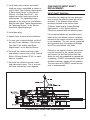
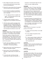
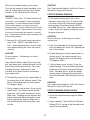
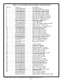
SERVICE MANUAL
HEAVY-DUTY E-SERIES INDEX DRIVES
MODELS
950E, 1150E, 1550E, 2050E
WARNING
This is a controlled document. It is your responsibility to deliver this information to the end user of the
CAMCO or FERGUSON product. Failure to deliver this could result in your liability for injury to the user or
damage to the machine. For copies of this manual, call your Customer Service Representative at 800-645-5207
TABLE OF CONTENTS
INTRODUCTION: . . . . . . . . . . . . . . . . . . . . . . . . . . . . . . . . . . . . . . . . . . . . . . . . . . . . . 2
WARNINGS AND CAUTIONS: . . . . . . . . . . . . . . . . . . . . . . . . . . . . . . . . . . . . . . . . . . . 2
SPARE PARTS KIT: . . . . . . . . . . . . . . . . . . . . . . . . . . . . . . . . . . . . . . . . . . . . . . . . . . . 3
BEFORE STARTING: . . . . . . . . . . . . . . . . . . . . . . . . . . . . . . . . . . . . . . . . . . . . . . . . . . 3
APPROXIMATE COMPONENT PART WEIGHT: . . . . . . . . . . . . . . . . . . . . . . . . . . . . . . 3
SPECIAL TOOLS: . . . . . . . . . . . . . . . . . . . . . . . . . . . . . . . . . . . . . . . . . . . . . . . . . . . . 3
DISASSEMBLY AND INSPECTION: . . . . . . . . . . . . . . . . . . . . . . . . . . . . . . . . . . . . . . . 5
DISASSEMBLY: . . . . . . . . . . . . . . . . . . . . . . . . . . . . . . . . . . . . . . . . . . . . . . . . . . . . . . 5
INSPECTION: . . . . . . . . . . . . . . . . . . . . . . . . . . . . . . . . . . . . . . . . . . . . . . . . . . . . . . . 5
OIL SEAL REPLACEMENT: . . . . . . . . . . . . . . . . . . . . . . . . . . . . . . . . . . . . . . . . . . . . . 6
OIL SEAL REMOVAL: . . . . . . . . . . . . . . . . . . . . . . . . . . . . . . . . . . . . . . . . . . . . . . . . . 6
OIL SEAL INSTALLATION: . . . . . . . . . . . . . . . . . . . . . . . . . . . . . . . . . . . . . . . . . . . . . . 6
CAM FOLLOWER REPLACEMENT: . . . . . . . . . . . . . . . . . . . . . . . . . . . . . . . . . . . . . . . 7
CAM FOLLOWER REMOVAL: . . . . . . . . . . . . . . . . . . . . . . . . . . . . . . . . . . . . . . . . . . . 7
CAM FOLLOWER INSTALLATION:. . . . . . . . . . . . . . . . . . . . . . . . . . . . . . . . . . . . . . . . 8
CAM AND/OR INPUT SHAFT REPLACEMENT:. . . . . . . . . . . . . . . . . . . . . . . . . . . . . . 9
INPUT SHAFT REMOVAL: . . . .
CAM REMOVAL: . . . . . . . . . . .
CAM INSTALLATION: . . . . . . .
INPUT SHAFT INSTALLATION:
INPUT PRELOAD TORQUE: . .
SETTING CAM: . . . . . . . . . . . .
.
.
.
.
.
.
.
.
.
.
.
.
.
.
.
.
.
.
.
.
.
.
.
.
.
.
.
.
.
.
.
.
.
.
.
.
.
.
.
.
.
.
.
.
.
.
.
.
.
.
.
.
.
.
.
.
.
.
.
.
.
.
.
.
.
.
.
.
.
.
.
.
.
.
.
.
.
.
.
.
.
.
.
.
.
.
.
.
.
.
.
.
.
.
.
.
.
.
.
.
.
.
.
.
.
.
.
.
.
.
.
.
.
.
.
.
.
.
.
.
.
.
.
.
.
.
.
.
.
.
.
.
.
.
.
.
.
.
.
.
.
.
.
.
.
.
.
.
.
.
.
.
.
.
.
.
.
.
.
.
.
.
.
.
.
.
.
.
.
.
.
.
.
.
.
.
.
.
.
.
.
.
.
.
.
.
.
.
.
.
.
.
.
.
.
.
.
.
.
.
.
.
.
.
.
.
.
.
.
.
.
.
.
.
.
.
.
.
.
.
.
.
.
.
.
.
.
.
.
.
.
.
.
.
.
.
.
.
.
.
.
.
.
.
.
.
.
.
.
.
.
.
9
13
13
14
15
15
FOLLOWER WHEEL AND/OR OUTPUT BEARING REPLACEMENT: . . . . . . . . . . . . . 17
FOLLOWER WHEEL REMOVAL: . . . .
OUTPUT BEARING REMOVAL: . . . . .
OUTPUT BEARING INSTALLATION: .
FOLLOWER WHEEL INSTALLATION:.
.
.
.
.
.
.
.
.
.
.
.
.
.
.
.
.
.
.
.
.
.
.
.
.
.
.
.
.
.
.
.
.
.
.
.
.
.
.
.
.
.
.
.
.
.
.
.
.
.
.
.
.
.
.
.
.
.
.
.
.
.
.
.
.
.
.
.
.
.
.
.
.
.
.
.
.
.
.
.
.
.
.
.
.
.
.
.
.
.
.
.
.
.
.
.
.
.
.
.
.
.
.
.
.
.
.
.
.
.
.
.
.
.
.
.
.
.
.
.
.
.
.
.
.
.
.
.
.
.
.
.
.
.
.
.
.
.
.
.
.
.
.
.
.
.
.
.
.
17
18
18
19
FINAL ASSEMBLY . . . . . . . . . . . . . . . . . . . . . . . . . . . . . . . . . . . . . . . . . . . . . . . . . . . . 19
HOW TO ORDER PARTS: . . . . . . . . . . . . . . . . . . . . . . . . . . . . . . . . . . . . . . . . . . . . . . 20
REQUIRED INFORMATION:.
TO ORDER PARTS: . . . . . . .
ON WARRANTY: . . . . . . . . .
ON NON-WARRANTY: . . . .
.
.
.
.
.
.
.
.
.
.
.
.
.
.
.
.
.
.
.
.
.
.
.
.
.
.
.
.
.
.
.
.
.
.
.
.
.
.
.
.
.
.
.
.
.
.
.
.
.
.
.
.
.
.
.
.
.
.
.
.
.
.
.
.
.
.
.
.
.
.
.
.
.
.
.
.
.
.
.
.
.
.
.
.
.
.
.
.
.
.
.
.
.
.
.
.
.
.
.
.
.
.
.
.
.
.
.
.
.
.
.
.
.
.
.
.
.
.
.
.
.
.
.
.
.
.
.
.
.
.
.
.
.
.
.
.
.
.
.
.
.
.
.
.
.
.
.
.
.
.
.
.
.
.
.
.
.
.
.
.
.
.
.
.
.
.
.
.
.
.
.
.
.
.
.
.
20
20
20
20
PARTS LIST 950E INDEX DRIVE (STANDARD CONFIGURATION) . . . . . . . . . . . . . . . 22
PARTS LIST 1150E INDEX DRIVE (STANDARD CONFIGURATION) . . . . . . . . . . . . . . 23
PARTS LIST 1550E INDEX DRIVE (STANDARD CONFIGURATION) . . . . . . . . . . . . . . 24
PARTS LIST 2050E INDEX DRIVE (STANDARD CONFIGURATION) . . . . . . . . . . . . . . 25
INTRODUCTION
This service manual pertains to the disassembly and assembly of CAMCO’s Heavy Duty "E" Series Index Drive models
950E, 1150E, 1550E & 2050E.
This manual is to be used in conjunction with the General Service Manual, which describes the lubrication and general
maintenance of CAMCO Index Drives.
A cross section view of a typical CAMCO Heavy Duty "E" Series Index Drive model 950E, 1150E, 1550E or 2050E is
included in this manual. Item numbers within this Service Manual refer to the cross section view. Also included is a
generic Bill of Materials for your convenience in identifying and ordering spare or replacement parts. Always provide
the serial number from the Index Drive when ordering spare or replacement parts.
Some users of Index Drives have facilities and trained personnel to accomplish service repair. You must determine the
extent to which intricate servicing should be done by your own maintenance personnel. When in doubt, CAMCO recommends the assistance of a CAMCO trained serviceman when making repairs.
CAMCO suggests that it is best to completely remove all tooling from CAMCO's Heavy Duty "E" Series Index Drive
prior to completing repairs. Realistically, removing all tooling from CAMCO's Heavy Duty "E" Series Index Drive is prohibitive. Tooling should be removed only as necessary in order to complete one or more of the following four related
procedures. The degree of disassembly increases with the addition of each procedure.
1. Input Oil Seal Replacement
Usually all tooling can be left in place when replacing oil seals. Removal of some portions of the drive package might
be required. See the section titled "Oil Seal Replacement" in this Service Manual for complete details.
2. Cam Follower Replacement
If the machine builder has provided access to the cam follower screws, the tooling does not need to be removed. Cam
followers can be replaced through the side access cover and follower access cover. See the section titled "Cam
Follower Replacement" in this Service Manual for complete details.
3. Input Shaft and/or Cam Replacement
In most cases, the input shaft and cam can be removed without removing all tooling. A section of the support structure and fixtures can be removed, or the support structure and fixtures can be lifted two to three feet above the unit
and supported by appropriate scaffolding. CAMCO recommends using professional machinery riggers for this purpose. The assistance of a CAMCO trained serviceman is recommended. See the section titled "Input Shaft and/or
Cam Replacement " in this Service Manual for complete details.
Follower Wheel and/or Output Bearing Replacement
In most cases, the follower wheel and/or output bearing cannot be removed without removing the major portion of any
support structure and fixtures. An overhead hoist, boom crane or similar device must be used to lift the follower wheel
and output bearing. In some cases, the support structure and fixtures can be lifted two to three feet above the unit and
supported by appropriate scaffolding. The follower wheel and output bearing can then be removed with a boom crane
or similar device. CAMCO recommends using professional machinery riggers for this purpose. The assistance of a
CAMCO trained serviceman is recommended. See the section "Follower Wheel and/or Output Bearing Replacement"
is this Service Manual for complete details.
WARNINGS AND CAUTIONS:
Statements in this manual proceeded by the words WARNING or CAUTION and printed in italics are very important.
CAMCO recommends you take special notice of these during service or repair.
WARNING
Means there is the possibility of personal injury to yourself or others.
CAUTION
Means there is the possibility of damage to the CAMCO unit.
2
SPARE PARTS KIT:
CAMCO offers a spare parts kit for all CAMCO index drive models manufactured by CAMCO. The spare parts kit for
CAMCO’s Heavy Duty "E" Series Index Drive includes input oil seals, input bearings, and input shims. Cam followers
are not included in the spare parts kit. CAMCO recommends a spare parts kit and cam followers be purchased and
kept on hand prior to any disassembly of your CAMCO E-Series Index Drive.
BEFORE STARTING:
CAMCO uses either Red Perma-Lok®‚ #HM118 or Green Perma-Lok®‚ #HM160 to secure most screws and set screws.
Exceptions are removable covers, etc. If you encounter a fastener that is difficult to remove, apply heat to the screw
and remove while still warm.
CAUTION
Localized heat can distort the part. Do not overheat any item.
WARNING
Disassembly and repair of a CAMCO Heavy Duty "E" Series Index Drive requires lifting and manipulating large cumbersome parts. Use the following table with approximate weights as a guide in selecting hoist, etc.
APPROXIMATE COMPONENT PART WEIGHT:
Index Drive
Input Shaft (lbs)
Cam (lbs)
Follower Wheel
Output Bearing
950E
205.0
400.0
720.0
250.0
1150E
335.0
800.0
1200.0
325.0
1550E
600.0
1350.0
2665.0
1200.0
2050E
915.0
3950.0
4950.0
1265.0
CAUTION
Disassembly and repair of a CAMCO Heavy Duty "E" Series Index Drive requires special tools not normally available. A
partial list of commercially available tools is provided. Some special tools and equipment must be manufactured by
maintenance personnel on site. Using the proper tool is mandatory for successfully completing repairs.
SPECIAL TOOLS:
Repair of any CAMCO Heavy Duty "E" Series Index Drive requires the following special tools,
1. Air Impact Wrench, 1" Drive, 2000 ft-lbs
2. Torque Wrench, 1" Drive, 2000 ft-lbs
3. Large Styrofoam container (Igloo‚ 50 or 60 gallon Ice Chest) three-quarters filled with dry ice.
The following special tools are unique to the individual "E" Series Index Drive.
Index Drive
Input Lock Nuts
950E
Spanner Wrench PN22
Cam Follower Screws
(H80 Flw.) 10MM Hex Socket, 1" Drive
(H96 Flw.) 14MM Hex Socket, 1" Drive
1150E
Spanner Wrench PN28
(H128 Flw.) 17MM Hex Socket, 1" Drive
1550E
Spanner Wrench PN36
(H128 Flw.) 17MM Hex Socket, 1" Drive
(H160 Flw.) 19MM Hex Socket, 1" Drive
2050E
Spanner Wrench PN36
(H192 Flw.) 22MM Hex Socket, 1" Drive
3
WARNING
CAMCO’s Heavy Duty "E" Series Index Drives cannot be "hand cranked" when completely assembled, i.e. with follower
wheel installed. During some portions of repair, the motor drive package is used to rotate the input shaft and follower
wheel. Some means for running the motor at extremely low speeds is mandatory. Use extreme caution when operating
the motor during repairs.
Before starting disassembly of your CAMCO unit you should read and review the following instructions. These provide
important information on parts and procedures necessary to successfully complete your repair.
Comply with all WARNINGS and CAUTIONS!
Read the "Trouble Shooting Guide" section in your "General Service Manual" before disassembling CAMCO units.
CAMCO recommends the assistance of a CAMCO trained serviceman whenever repairs are more involved than replacing oil seals or cam followers.
TORQUE REQUIREMENTS FOR TIGHTENING SCREWS:
The included table provides torque specification for US Standard and Metric Socket Head Cap Screw. Refer to
CAMCO’s "General Service Manual" for a complete listing of torque specification by grade and material.
US Standard Socket Head Cap Screw
Metric Socket Head Cap Screw
Thread Size
Torque (ft/lbs)
Thread Size
Torque (ft/lbs)
.250-20
12
M6
12
.312-18
24
M8
29
.375-16
45
M10
57
.500-13
110
M12
100
.562-12
150
M14
159
.625-11
210
M16
243
.750-10
380
M20
479
1.00-8
910
M24
811
1.125-7
1290
M30
1637
Torque values are for non-lubricated threads, coated only with a residual film of oil, as received from the manufacturer.
Values are for threads engaged 1.5 times the screw thread diameter and installed into steel parts.
4
DISASSEMBLY AND INSPECTION:
2.2. Visually observe the surface of the
outer shell. Inspect followers for
damage or radial looseness.
Looseness should not exceed .001
inch. Do not confuse radial looseness
with axial endplay. End play will be
from .03 to .06 inch as a normal condition. If endplay exceeds .06 inch
the followers should be replaced.
DISASSEMBLY:
1. Remove only those structural members
and fixtures required to gain access to
the index drive and to allow for completing the necessary procedures.
2. Drain oil and flush with flushing solvent.
Retain any chips or broken pieces you
may find. These may aid in diagnosis.
NOTE: Generally, cam followers are replaced
as added insurance against later failure.
When in doubt, replace the cam followers.
2.1. Oil may be drained by removing
Magnetic Drain Plug (Item #23).
3. Broken cam followers indicate possible
damage to the follower wheel. Remove
any broken cam followers. See the section titled "Cam Follower Replacement",
in this Service Manual. Inspect the cam
follower stud hole in the follower wheel
for damage, and to determine whether
the cam follower stud hole is "wallowed
out", elongated, oval, etc. Using the
nominal size of the cam follower stud as
a guide, verify a press fit between the
stud and the hole, -. 0005 to -. 0010 inch
for the full length of the hole.
2.2. Alternatively, oil may be drained by
removing Cover (Item#7) and pumping
the oil from the unit's sump.
3. Remove socket head cap screws (Item #
27) and Cover (Item #6).
INSPECTION:
1. While slowly rotating input, inspect cam
(Item #4) surface to determine if cam must
be replaced. Inspect for a rough or rippled surface, gouge marks, pitting and
other imperfections.
4. Wobbling of the output or grinding noises
during each index indicate damage to
the output bearing (Item #5). Further
inspection requires removal of the follower wheel. See the section titled
"Follower Wheel and Output Bearing
Replacement" in this Service Manual.
WARNING
CAMCO's Heavy Duty "E" Series Index Drives
cannot be "hand cranked" when completely
assembled, i.e. with follower wheel installed.
During some portions of repair, the motor
drive package is used to rotate the input shaft
and follower wheel. Some means for running
the motor at extremely low speeds is mandatory. Use extreme caution when operating the
motor during repairs.
5. Replace cam followers if loose in dwell or
if the outer shell is visibly damaged. See
the section titled "Cam Follower
Replacement" in this Service Manual.
6. Replace the cam if imperfections are
noted. See the section titled "Cam
and/or Input Shaft Replacement" in this
Service Manual.
2. Slowly index the unit and place the Index
Drive in a dwell position.
2.1. While manually applying torque to
the output follower wheel (Item #2),
check for pre-load in dwell. Try to
rotate the cam followers (Item #14)
that are in dwell.
7. Replace the follower wheel if holes are
oversized. See the section titled
"Follower Wheel and Output Bearing
Replacement" in this Service Manual.
5
OIL SEAL REPLACEMENT:
diameter is bent or otherwise damaged, replace the oil seal.
CAMCO recommends replacing the Input oil
seals (Item #13) anytime the input is disassembled regardless of whether they are damaged or not. After being in service for some
time, the sealing lip can become brittle and
easily cracked. Most damage to oil seals
occurs at assembly when recommended seal
installation procedures are not followed.
2. Check the input shaft for surface nicks,
burrs or a groove from the sealing lip.
Look for spiral machine marks that can
damage the seal lip.
2.1. An input shaft with a groove from the
sealing lip can be repaired with a
Chicago Rawhide Speedi-Sleeve‚ or
similar product from another manufacturer. Consult the manufacturer for
installation instructions.
To replace the oil seal on the reducer side of
the index drive, remove the reducer and additional drive equipment as necessary to gain
access to the seal. See the reducer and other
manufacturers’ Service Manuals for instructions on removing this equipment. On the
other side of the index drive, remove visual
dwell indicator or other equipment as necessary to gain access to the oil seal.
2.2. Alternatively, the input shaft could be
replaced instead of repaired.
3. Check the end of the input shaft and
remove any burrs or sharp edges. The
end of the shaft should be chamfered.
OIL SEAL REMOVAL:
4. Check splines and keyways for burrs or
sharp edges.
1. To remove the oil seal, use a sharp punch
and punch two (2) diametrically opposed
holes through the case of the seal. Install
sheet metal screws into the holes.
5. Wrap the input shaft with plastic shim
stock as a temporary sleeve to guide and
protect the sealing lip.
2. Use a Slide Hammer or Pliers (Vise Grips‚)
to grip the sheet metal screws to pull out
the existing seal.
6. Check the sealing lip direction. Make
sure the new seal faces the same direction as the original. CAMCO's standard
practice is to mount the seal so the lip
faces the lubricant or fluid to be sealed.
CAUTION
Do not drill holes in the case of the seal.
Chips will get into the unit and they cannot be
easily removed. A punched hole provides a
better "bite" when installing sheet metal
screws into the metal case.
7. Pre-lubricate the sealing element by wiping the surface with the lubricant being
retained. Apply a thin layer of "General
Electric Silicone Rubber RTV-6" or equivalent to the cartridge bore as a sealant.
When the seal in pressed into place, a
bead of sealant will form at the back edge
of the steel case and prevent any leakage
around the outside edge of the seal.
OIL SEAL INSTALLATION:
1. Check new seal for damage that may
have occurred prior to installation.
1.1. An oil seal with a sealing lip that is
turned back, cut or otherwise damaged
should be replaced and not used.
8. Whenever possible use an installation tool
that has been specifically manufactured
for installing the seal.
1.2. Likewise, if the outer face or outside
6
8.1. Installation tools should have an outside diameter .010 inch smaller than
the bore size. The bore should be
.005 larger than the shaft size, and the
face of the tool should be relieved so
that pressure is applied only near the
outside diameter of the seal.
cam followers, pack all new cam followers in
a large Styrofoam container (Igloo‚ 50 or 60
gallon Ice Chest) three-quarters filled with dry
ice.
1. Remove socket head cap screws
(Item # 32) and remove side access
cover (Item #10)
8.2. During installation press the seal
flush to the cartridge face to avoid
cocking the seal in the bore. This also
positions the seal correctly on the
shaft.
2. Once this cover is removed you may
view inside to locate the follower access
cover (Item #9). Remove the socket head
cap screws (Item #25) and remove this
cover.
9. When an installation tool cannot be manufactured, install the seal by tapping uniformly around the seal with a soft hammer. Avoid cocking the seal and make
sure the face of the seal is square to the
bore.
CAM FOLLOWER REPLACEMENT:
CAM FOLLOWER REMOVAL:
Instructions for replacing cam followers
assume the cam and follower wheel will not
be removed. If the follower wheel will be
removed, proceed to the section titled
"Follower Wheel and/or Output Bearing
Replacement" in this Service Manual.
Likewise, if the cam will be removed, proceed
to the section titled "Cam and/or Input Shaft
Replacement" in this Service Manual.
Otherwise, proceed with the following steps.
CAM FOLLOWER REPLACEMENT
E-SERIES INDEX DRIVES
3. Use the motor and drive package to
rotate the input shaft and follower wheel
until a follower is positioned directly
above and centered on the removal
opening.
WARNING
CAMCO’s Heavy Duty "E" Series Index Drives
cannot be "hand cranked" when completely
assembled, i.e. with follower wheel installed.
During some portions of repair, the motor
drive package is used to rotate the input shaft
and follower wheel. Some means for running
the motor at extremely low speeds is mandatory. Use extreme caution when operating the
motor during repairs.
If the machine builder has provided access to
the cam follower screws, the tooling does not
have to be removed. Otherwise the support
structure and fixtures can be removed as necessary, or the support structure and fixtures
can be lifted two to three feet above the unit
and supported by appropriate scaffolding.
CAMCO recommends using professional
machinery riggers for this purpose. The
assistance of a CAMCO trained serviceman
is recommended.
At least three (3) hours before installing new
7
WARNING
Use protective gloves while handling cam followers after they have been packed in dry ice.
4. Remove bore plug (Item #33), the cam
follower screw (Item #15) and the heavy
washer (Item #9). CAMCO used Red
Perma-Lok‚ to secure these screws If
you encounter difficulty when removing
the screw, apply heat to the screw and
remove while still warm.
1. Coat the follower wheel stud hole with
anti-seize lubricant. Using quick sure
movements, place a cam follower that
has been packed in dry ice for at least
three (3) hours into the follower wheel
hole.
CAUTION
Localized heat can distort the part. Do not
overheat any item.
1.1. Using a twisting motion of the hand,
push the cam follower upward hard
enough to press the cam follower into
the follower wheel hole. Make sure the
shoulder on the cam follower seats
against the follower wheel. Do not
rush the process; just proceed quickly
and with sure movements.
5. Using a large soft faced hammer, drive
the cam follower downward and out
through the follower wheel.
6. Inspect each cam follower stud hole for
roundness and size. The cam follower
stud hole must be a interference fit. The
cam follower holes must be -.0005 to .0010 inch for the full length of the hole.
Check the follower holes for roundness.
These holes should be round within .0005
TIR of an inch to permit reuse of the
follower wheel. These holes may be
worn-out due to overloads.
1.2. If the cam follower cannot be seated
by using a twisting motion of the hand
and pushing upward, use a soft faced
hammer to drive the cam follower into
the follower wheel.
1.3. Alternatively, pull the cam follower
into place using the cam follower
screw, heavy washer and tapped hole
in the cam follower stud.
CAUTION
Do not use a follower wheel with oversize follower holes. The cam followers and cam will
fail prematurely.
1.4. In a worst case, place a steel plate
against the bottom of the cam follower
and use a hydraulic jack to push the
cam follower into the follower wheel.
CAM FOLLOWER INSTALLATION:
The instructions for replacing cam followers
assume the follower wheel and cam were not
removed. Cam followers will be installed one
at a time through the follower access hole in
the housing. If the follower wheel was
removed, proceed by repeating the first four
steps until all cam followers have been
installed in the follower wheel.
CAUTION
Make sure the shoulder of the cam follower is
seated against the follower wheel and make
sure the follower is installed straight and in
line with the hole. Damage to the cam
follower, follower wheel or cam could occur if
cam follower is improperly aligned during
installation.
If the cam was removed but not the follower
wheel, proceed by repeating the first four
steps until all but two cam followers have
been replaced. Also see additional instructions below.
8
CAM AND/OR INPUT SHAFT
REPLACEMENT:
2. Install heavy-duty washer and socket
head cap screw, assembled as shown in
sketch titled "Cam Follower Replacement
E-Series Index Drives" in this Service
Manual. Use Red Perma-Lok®‚ and
torque the socket head cap screw to
specification. The tightening torque
depends on the size of the cam follower.
See the table titled "Torque Requirements
for Tightening Screws" in this Service
Manual for tightening torque.
INPUT SHAFT REMOVAL:
Instructions for removing the cam and input
shaft assume the follower wheel will not be
removed. If the follower wheel will be
removed, proceed to the section titled
"Follower Wheel and/or Output Bearing
Replacement" in this Service Manual.
Otherwise, proceed with the following steps.
3. Install bore plug.
If the machine builder has provided access
holes to the cam follower screws, complete
removal of the support structure and fixtures
is not mandatory. The cam can be supported
during removal with a threaded rod through
one of the cam follower stud holes.
4. Repeat steps to install all cam followers.
5. If a new cam is being installed, install all
but two (2) cam followers. See the section titled "Cam and/or input Shaft
Replacement" in this Service Manual.
Otherwise, the support structure and fixtures
must be removed, or the support structure
and fixtures can be lifted two to three feet
above the unit and supported by appropriate
scaffolding. CAMCO recommends using professional machinery riggers for this purpose.
The assistance of a CAMCO trained serviceman is recommended.
6. Re-install the socket head cap screws
and follower access cover, using "General
Electric Silicone Rubber RTV-6" or equivalent as a sealant.
7. Re-install the socket head cap screws
and side access cover. This is an external cover and sealant is not required.
E-SERIES INPUT SHAFT AND CAM REMOVAL
9
1. Remove two or three cam followers. See
section titled "Cam Follower Removal" in
this Service Manual for detailed instructions on cam follower removal.
5. Depending on whether the follower wheel
was removed, proceed as follows.
5.1. Follower wheel was not removed.
2. While referring to the sketch titled
"E-Series Input Shaft And Cam
Removal", proceed as follows.
5.1.1. Use the motor drive package to
rotate the input shaft and rotate the
follower wheel through motion until a
position is reached where one of the
previously removed cam followers
starts to enter the cam.
3. Bend lockwasher (Item #20) tabs over
and away from locknut.
4. Loosen the locknuts (Item #19) that
secure the cam to the input shaft (Item
#3). CAMCO uses Green Perma-Lok‚ to
secure the locknuts. If you encounter difficulty, apply heat to the locknut and
remove while still warm.
WARNING
CAMCO’s Heavy Duty "E" Series Index Drives
cannot be "hand cranked" when completely
assembled, i.e. with follower wheel installed.
During some portions of repair, the motor
drive package is used to rotate the input shaft
and follower wheel. Some means for running
the motor at extremely low speeds is
mandatory. Use extreme caution when operating the motor during repairs.
CAUTION
Localized heat can distort the part. Do not
overheat any item..
4.1. Use a Spanner Wrench that has been
locked (jammed) against the top or
bottom of the housing to hold the
locknut while turning the input shaft.
Use the motor drive package to rotate
the input shaft and break loose the
locknuts.
5.1.2. Rotate the follower wheel until the
position of one removed cam follower
is directly above the tapped "lifting
hole" in the cam. See sketch titled
"E-Series Input Shaft and Cam
Removal" in this Service Manual.
5.1.3. Install threaded rod into the "lifting hole" in the cam and let the
threaded rod extend beyond the top
surface of the follower wheel. Put a
hex nut on the threaded rod and run
it down until the nut is tight against
the cam. The length of the extension
should be sufficient to lower the cam
into the bottom of the housing.
WARNING
CAMCO’s Heavy Duty "E" Series Index Drives
cannot be "hand cranked" when completely
assembled, i.e. with follower wheel installed.
During some portions of repair, the motor
drive package is used to rotate the input shaft
and follower wheel. Some means for running
the motor at extremely low speeds is mandatory. Use extreme caution when operating the
motor during repairs.
5.1.4. Place a piece of plate (approximately 1/2" x 6" x 6") with a hole
through the center over the threaded
rod. This plate will act like a large
washer for supporting the cam during
removal of the input shaft. See
sketch titled "E-Series Input Shaft
and Cam Removal" in this Service
Manual.
4.2. Break loose the locknuts, don’t completely loosen or remove them from the
threaded portion of the input shaft.
4.3. In some cases it might be necessary
to split the locknut before it will break
loose. Use a cold chisel or other suitable tool for this purpose.
10
5.1.5. Put a hex nut on the threaded rod
and run it down until the nut is snug
against the plate and until the threaded rod is supporting the weight of
the cam.
7. Match mark the bearing cartridges.
Eccentric cartridges are used in E-Series
Index Drives to accommodate different cam
diameters. The cartridges must be
replaced in the same orientation as when
removed. Remove all socket head cap
screws (Item #24) securing the two (2)
bearing cartridges (Item #11) to the
housing (Item #1) and remove the bearing
cartridges.
Note: The hole in the follower wheel and the
tapped hole in the cam do not line up exactly.
The threaded rod might be at a slight angle
until the bearing cartridges are removed. This
is acceptable, the threaded rod will straighten
out when the bearing cartridges are removed.
If threaded rod cannot be installed at this
time, place wooden blocks under the cam for
support and install threaded rod after removing the bearing cartridges.
7.1. This can be done by striking the cartridge with a soft faced hammer to break
any sealant and then prying the cartridge
away from the housing.
7.2. The input oil seal (Item #13) and input
bearing cup (Item #17) will stay with
each bearing cartridge when it is
removed. See sketch titled "E-Series
Input Shaft and Cam Removal" in this
Service Manual.
5.2. Follower wheel was removed.
5.2.1. Install threaded rod into the "lifting hole" in the cam and let the
threaded rod extend beyond the top
surface of the housing. Put a hex nut
on the threaded rod and run it down
until the nut is tight against the cam.
The length of the extension should be
sufficient to lower the cam into the
bottom of the housing.
7.3. Make sure to note the color and number of any input shims (Item #12) at each
cartridge. The color and number of
shims used determines bearing preload.
8. Remove the input bearing cone (Item #17)
on the side of the input shaft with the
shortest extension.
5.2.2. Place a piece of plate (approximately 3/4" x 6" x 36") with a hole
through the center over the threaded
rod. This plate sitting on the top
edge of the housing (or output bearing) will act as a support during
removal of the input shaft. See
sketch titled "E-Series Input Shaft
and Cam Removal" in this Service
Manual.
8.1. The input bearing can be knocked off
with an aluminum bar from the inside of
the housing.
8.2. Alternatively a bearing puller can be
used to remove the bearing.
9. Completely remove the locknuts and lockwashers on the side of the input shaft with
the shortest extension. Loosen the locknuts and lockwashers on the other side of
the input shaft until they are completely off
the threaded portion of the input shaft.
5.2.3. Put a hex nut on the threaded rod
and run it down until the nut is snug
against the plate and the threaded
rod is supporting the weight of the
cam.
6. Remove the reducer and any portion of the
drive package that would interfere with
removal of the input shaft.
10. Mount a puller to the housing on the side
of the input shaft with the shortest extension. Use the tapped holes in the housing
that were exposed when the bearing
11
cartridges were removed. See sketch titled
"E-Series Input Shaft and Cam Removal" in
this Service Manual.
sure the input shaft doesn’t fall when the end
is pushed out of the cam and becomes
unsupported.
10.1. Using diametrically opposed tapped
holes, install two (2) threaded rods into
the tapped holes. These rods should
extend beyond the end of the input shaft
sufficiently to allow for a hydraulic jack.
13. Before proceeding, inspect the keyway in
the input shaft to make sure they are to
size. Also, inspect the oil seal diameters
for burrs, scratches, nicks or dings
13.1. An oversize keyway must be
remanufactured to proper specification.
10.2. Between the threaded rods mount a
2" square bar with clearance holes to
allow the threaded rod to pass through
the bar.
13.2. Alternatively, the input shaft must be
replaced.
10.3. Use hex nuts and washers on both
sides of the 2" square bar to secure the
bar to the threaded rod.
CAUTION
Loose fitting keys can cause premature failure
of the index drive.
10.4. Place a hydraulic jack between the
2" square bar and the end of the input
shaft. A 15 ton or 20 ton hydraulic jack
is suggested.
14. Any imperfections must be removed from
the oil seal surface on the input shaft.
Otherwise, the oil seal will leak.
11. Mount wood blocks between the cam
and the housing to provide support (hold
cam in position) when pushing the input
shaft through and out of the cam.
14.1. If an imperfections can not be
"polished" out, resurface the oil seal
diameter.
14.2. An alternative to resurfacing the oil
seal diameter is a wear sleeve. See the
section titled " Oil Seal Replacement" in
this Service Manual.
11.1. On the side opposite the puller, the
side of the input shaft with the long shaft
extension, measure the distance
between the cam and the housing. Cut
wood blocks that sit on the bottom of
the housing and rest against the cam
and side of the housing to prevent the
cam from moving laterally, i.e. so a
hydraulic jack can be used to push out
the input shaft.
15. Prepare the input shaft for assembly by
removing the remaining locknuts and lockwasher and bearing cone from the input
shaft.
16. Remove the bearing cups from the
bearing cartridges, and remove the used
oil seals from the bearing cartridges.
12. Using a hydraulic jack, push the input
shaft through the cam and out of the unit.
16.1. Measure the overall (stack) height of
the bearing cones and bearing cups.
CAUTION
Support the input shaft as it is pushed out of
the cam. Use a boom crane or other means
for supporting the input shaft. See
"Approximate Weights" within this service
manual for sizing the lifting device. Make
16.2. Record these values with the previously recorded values for input shim.
12
tion where one or more cam followers are
over the housing cavity. Use a come-a-long
or other device to pull the follower wheel and
any attached tooling into position. Two or
three cam followers can be accessed through
the large access opening in the housing. See
section titled "Cam Follower Replacement" in
this Service Manual.
CAM REMOVAL:
1. Once the input shaft has been removed,
use one of two methods to lower the cam
into the bottom of the housing.
1.1. Use a lift ring on the end of the treaded
rod and a boom crane to lift the cam
slightly, i. e. to relieve strain on the hex
nut. Then while using the lift ring to
support the cam, loosen the hex nut and
back it off several inches. Use the
boom crane to lower the cam into the
bottom of the housing. See sketch titled
"E-Series Input Shaft and Cam
Removal" in this Service Manual.
Do not install the last two (2) cam followers
until the input shaft and cam have been
installed.
Once all but two (2) cam followers have been
replaced, place the cam inside the housing
cavity.
1. Before placing the cam inside the housing
cavity, check the input shaft diameter and
the cam bore size to ensure a slip fit.
1.2. Or without using a lift ring (no access
for a boom crane), slowly loosen the hex
nut and lower the cam into the bottom of
the housing.
1.1. The input shaft can be installed in the
cam and then removed to ensure a slip fit.
CAUTION
See "Approximate Weights" within this service
manual for sizing the lifting device. Make sure
the cam is supported.
1.2. If the input shaft binds during installation,
hone the cam bore to provide a slip fit.
CAUTION
The cam must be a slip fit or slight press fit,
but the fit cannot be loose. Do not remove an
excessive amount of material.
2. Once the cam is sitting on the bottom of
the housing, remove the threaded rod, etc.
3. Use one of two methods to get the cam out
of the housing cavity.
3.1. Place a "Nylon Strap" through the bore
of the cam, and while pulling on the
strap, roll the cam out of the housing.
2. The cam can be either rolled into the housing cavity, or it can be lifted and pushed
into the housing cavity. Use the best
method as determined by the situation.
3.2. Alternatively, insert a piece of threaded
rod with a lift ring into the tapped hole in
the cam and using the lift ring, pull the
cam out of the housing cavity.
3. Regardless of the method used to place the
cam in the housing cavity, placing the cam
into the housing cavity will be an awkward
process.
CAM INSTALLATION:
CAUTION
Make sure the cam is not damaged during this
process.
Instructions for replacing the cam assume the
follower wheel was not removed.
4. Install threaded rod and lift ring into the lifting hole in the cam. Then lift the cam so
the input shaft can be pushed through the
cam.
Before proceeding with installation of the new
cam, install all but two new cam followers.
Manually pull the follower wheel into a posi13
4.1. Reverse one of the methods described
for lowering the cam into the housing
when lifting the cam. See section titled
"Cam and/or Input Shaft Replacement"
in this Service Manual.
CAUTION
Make sure the bearing is seated against the
shaft shoulder. Improper mounting of the
bearing can cause premature failure.
3.5. If the bearing does not immediately
seat against the shaft shoulder, use a
piece of tubing over the shaft and against
the bearing, and a soft hammer to drive
the bearing against the shoulder.
INPUT SHAFT INSTALLATION:
1. Prepare the input shaft for installation by
installing the locknuts and lockwasher on
the side of the input shaft with the long
shaft extension.
4. Install the input shaft from the long extension side of the shaft.
1.1. Just start the locknuts onto the threaded portion of the input shaft. They will
be snugged up later and tightened after
setting the cam.
5. The input shaft should be a slip fit to slight
press fit into the cam. Use a rocking hand
motion and push the input shaft through
the cam.
2. Measure the overall (stack) height of the
new bearing cones and bearing cups.
5.1. If the shaft becomes stuck, hit the end
of the input shaft with a soft faced hammer and drive the input shaft through the
cam.
2.1. Compare the measured values to the
same values as measured on used bearing cones and bearing cups.
5.2. In a worst case, use a hydraulic jack to
push the input shaft through the cam.
See section titled "Cam and/or Input
Shaft Replacement" in this Service
Manual for construction of a puller and
installation of wood blocks between the
cam and the housing to provide support
(hold cam in position) while pushing the
input shaft through the cam.
2.2. Use this measurement to adjust the
amount of input shim used when
installing the new bearings.
3. Install a new bearing cone onto the long
extension of the input shaft.
3.1. Coat the shaft with anti-seize lubricant
prior to installation.
6. Install locknuts and lockwasher on the
opposite side of the cam. Inspect and
reuse existing locknuts and lockwashers if
they are not damaged.
3.2. Heat a new bearing cone in a commercial bearing oven that has been designed
for this purpose. Heat evenly to about
250˚F.
6.1. Just start the locknuts onto the threaded portion of the input shaft. They will
be snugged up later and tightened after
setting the cam.
3.3. Alternatively. heat the bearing with a
heat gun.
WARNING
Use protective gloves while handling bearings
after they have been heated in an oven.
7. Install a new Bearing Cone onto the short
extension of the input shaft.
3.4. Using a twisting motion of the hand,
push the bearing cone against the shoulder on the input shaft.
7.1. Coat the shaft with anti-seize lubricant
prior to installation.
14
7.2. Heat a new Bearing Cone in a commercial bearing oven that has been designed
for this purpose. Heat evenly to about
250˚F.
11.1. Endplay in the input shaft is not
permissible. There should be preload on
the input bearings. Use a dial indicator
and a pry bar to check for endplay.
7.3. Alternatively, heat the bearing with a
heat gun.
11.2. Heavier preload is preferred to endplay. Remove input shim if end play is
detected.
WARNING
Use protective gloves while handling bearings
after they have been heated in an oven.
11.3. With just the input shaft, cam and oil
seals installed, preload can be measured
with a torque wrench. An adapter
between the input shaft and torque
wrench is required, and the torque
wrench must be capable of measured
torque values up to 6000 in-lbs. See the
table titled "Input Preload Torque" in this
Service Manual.
7.4. Using a twisting motion of the hand,
push the Bearing Cone against the shoulder on the input shaft.
CAUTION
Make sure the bearing is seated against the
shaft shoulder. Improper mounting of the
bearing can cause premature failure.
INPUT PRELOAD TORQUE:
7.5. If the bearing does not immediately
seat against the shaft shoulder, use a
piece of tubing over the shaft and
against the bearing, and a soft hammer
to drive the bearing against the shoulder.
Camco E-Series Index Drive
950E
1150E & 1550E 2050E
Input Preload Min.– Max.(in-lbs)
500 - 2000 1000 – 4000
2000 - 6000
CAUTION
End play in the input shaft will cause
premature failure of the Index Drive.
8. Use an Arbor Press to press the bearing
cups to the input cartridges.
8.1. Coat the outside of the bearing cup
with anti-seize lubricant prior to pressing
into cartridge.
12. Re-install the reducer and any portion of
the drive package that was previously
removed.
9. Re-install the bearing cartridges.
CAUTION
Make sure the hollow shaft of the reducer and
the input shaft is properly aligned.
Misalignment of the reducer and input shaft
will cause premature failure of the Index Drive.
9.1. Use duplicate shims to those previously removed, but adjust the shims for
the measured height of the bearings.
9.2. Apply a small bead of "General Electric
Silicone Rubber RTV-6" at the intersection of the pilot diameter and flange
before installing the bearing cartridges.
SETTING CAM:
1. Install a dowel pin in the hole provided in
the upper wall of the housing. The diameter varies depending on which E-Series
Index Drive is being repaired. Polish the
dowel pin as necessary to provide a slip fit
into the hole.
10. Install new oil seals. See section titled
"Oil Seal Replacement" in this Service
Manual for detailed instructions.
11. Check for input shaft endplay.
15
2. With a depth micrometer, measure from
the face of the dwell track on one side of
the cam to the dowel pin.
resistance is encountered, adjust the cam
axially to a more suitable position.
WARNING
CAMCO Heavy Duty "E" Series Index Drives
cannot be "hand cranked" when completely
assembled, i.e. with follower wheel installed.
During some portions of repair, the motor
drive package is used to rotate the input shaft
and follower wheel. Some means for running
the motor at extremely low speeds is mandatory. Use extreme caution when operating the
motor during repairs.
3. Repeat this measurement from the opposite
face of the dwell track to the dowel pin.
4. Use the locknuts to adjust the position of
the cam relative to the dowel pin until the
cam is centered.
4.1. Use a Spanner Wrench to tighten the
lugnut. Final tightening will occur after
the cam has been set.
11. Repeat the process of applying Prussian
Blue until the unit performs smoothly and
the bluing pattern is quite uniform and there
is no looseness in any dwell position. Index
the unit through several indexes and check
the entrance tips on all tracks.
5. Manually rotate the follower wheel to
engage the first cam follower into the cam.
6. With the motor and drive package rotate
the input shaft until the cam followers are
engaged in the cam. Continue rotating the
input shaft and follower wheel until the follower stud hole is positioned directly above
and centered on the follower access hole.
CAUTION
There should be no looseness in any dwell
position of the output.
WARNING
CAMCO's Heavy Duty "E" Series Index Drives
cannot be "hand cranked" when completely
assembled, i.e. with follower wheel installed.
During some portions of repair, the motor
drive package is used to rotate the input shaft
and follower wheel. Some means for running
the motor at extremely low speeds is mandatory. Use extreme caution when operating the
motor during repairs.
11.1. Make sure Prussian Blue is still visible
on all tips.
11.2. If not, readjust the position of the
cam and repeat.
11.3. If after several attempts to adjust the
cam, Prussian Blue is not visible on all
tips, hand grind the tips of the entrance
track to provide relief.
7. Install a new cam follower in this position.
See section titled "Cam Follower
Installation" in this Service Manual.
CAUTION
The tips of the cam cannot be relieved prior to
installation. This procedure must be completed while installing the cam.
8. Repeat these steps until all remaining cam
followers have been installed.
CAUTION
Do not grind tips excessively.
9. Apply Loctite‚ Prussian Blue #30520 or
equivalent to both sides of the entire cam
track.
CAUTION
Tip relief must be evident. If tips are not properly relieved, the cam followers will hit the tips
when entering the cam. Eventually, this will
crack the cam follower shell. Catastrophic
damage will occur.
10. Using the motor and drive package
slowly rotate the input shaft and cam. If
16
FOLLOWER WHEEL AND/OR
OUTPUT BEARING REPLACEMENT:
12. Once proper contact has been assured,
use the following procedure to tighten the
locknuts and secure the lockwasher tabs.
FOLLOWER WHEEL REMOVAL:
12.1. Back off both locknuts and the lockwasher on one side of the cam.
In most cases, the follower wheel and/or output bearing cannot be removed without
removing the major portion of any support
structure and fixtures. An overhead crane or
similar device must be used to lift the follower
wheel and output bearing. In some cases, the
support structure and fixtures can be lifted
two to three feet above the unit and supported by appropriate scaffolding. The follower
12.2. Apply Green Perma-Lok‚ to the
threads on the input shaft.
12.3. Use a Spanner Wrench that has been
locked (jammed) against the top or bottom of the housing to hold the locknut
while turning the input shaft. Use the
motor drive package to rotate the input
shaft and tighten the locknut.
12.4. Repeat the previous step to tighten
the second locknut on the same side of
the cam.
WARNING
CAMCO’s Heavy Duty "E" Series Index Drives
cannot be "hand cranked" when completely
assembled, i.e. with follower wheel installed.
During some portions of repair, the motor
drive package is used to rotate the input shaft
and follower wheel. Some means for running
the motor at extremely low speeds is mandatory. Use extreme caution when operating the
motor during repairs.
DWELL POSITION, E-SERIES INDEX DRIVES
13. Bend over the lockwasher tabs towards
the locknut and into the slot.
wheel and output bearing can then be
removed with a boom crane or similar device.
CAMCO recommends using professional
machinery riggers for this purpose. The
assistance of a CAMCO trained serviceman
is recommended.
CAUTION
A torque specification for locknuts is not available. Make sure they are tight!
14. Repeat the above steps and tighten the
locknuts on the opposite side of the cam.
1. Use the motor drive package to position
the input shaft keyway such that the cam is
just entering dwell.
15. After tightening locknuts, re-apply
Prussian Blue and check for tip relief etc.
Note: For most Camco E-Series Index Drives
this is ten to fifteen (10˚ - 15˚) degrees clockwise or counter-clockwise from the mid-dwell
position.
17
Refer to the model number of your Index
Drive for the amount of dwell provided. Also
refer to "Interpretation of Index Drive Model
Number" in the General Service Manual.
CAUTION
See "Approximate Weights" within this Service
Manual for sizing the lift device.
OUTPUT BEARING REMOVAL:
WARNING
CAMCO’s Heavy Duty "E" Series Index Drives
cannot be "hand cranked" when completely
assembled, i.e. with follower wheel installed.
During some portions of repair, the motor
drive package is used to rotate the input shaft
and follower wheel. Some means for running
the motor at extremely low speeds is mandatory. Use extreme caution when operating the
motor during repairs.
1. If the output bearing (Item #2) is to be
replaced, remove the 16 to 40 socket head
cap screws (Item #30) fastening the output
bearing (Item #6) to the housing. CAMCO
used Red Perma-Lok‚ when tightening these
screws and it may require heating the screw
for ease of removal.
CAUTION
Do not overheat. Overheating can distort
mating parts.
2. Remove 16 to 40 socket head cap screws
(item # 28). CAMCO used Red PermaLok®‚ when tightening these screws and it
may require heating the screw for ease of
removal.
2. From the underside of the housing flange,
drive the dowel pins (Item # 31) upward and
out of the bearing.
CAUTION
Do not overheat. Overheating can distort
mating parts.
3. Thread lifting eyes into the tapped holes in
the top face of the output bearing. (two
places 180 degrees apart or three places
120 degrees apart).
Note: Some E-Series Index Drives may have
pull type dowel pins installed between the follower wheel and output bearing. This is not
standard practice. If dowel pins were
installed, use a Slide Hammer and remove
these dowel pins.
4. Using a boom crane or hoist, lift up the
output bearing. The output bearing should
break free at this point and permit lifting it
clear. If binding occurs, break the output
bearing free by tapping the bearing with a
soft faced hammer, alternating from side to
side.
3. Thread lifting eyes into the tapped holes in
the output face of the follower wheel. (Two
places 180 degrees apart or three places
120 degrees apart).
CAUTION
See "Approximate Weights" within this Service
Manual for sizing the lift device.
4. Using a boom crane or hoist, lift up the follower wheel. The follower wheel should
break free at this point and permit it to be
lifted clear. If binding occurs between the
output wheel and the locating pilot, break
free by tapping the follower wheel with a
soft faced hammer, alternating from side
to side.
OUTPUT BEARING INSTALLATION:
1. Install the output bearing using the following steps.
2. Apply a bead of "General Electric Silicone
Rubber RTV-6" on top of the housing in the
area of bearing contact.
18
3. Thread lifting eyes into the threaded holes
in the bearing (two places 180 degrees
apart or three places 120 degrees apart)
and using a boom crane or hoist set the
bearing onto the housing.
1.3. If used, install pull type dowel pins.
Apply Red Perma-Lok.
1.4. Install 16 to 40 socket head cap
screws. Tighten to specification. See
table titled “Torque Requirements For
Tightening Screws” in this Service
Manual.
4. Coat the dowel pin holes with anti-seize
lubricant and drive the dowel pins through
the bearing and into the housing.
FINAL ASSEMBLY:
5. Apply Red Perma-Lok‚ and install 16 to 40
socket head cap screws. Tighten to specification. See "Metric Screw Tightening
Torques" in this Service Manual.
1. Reinstall the Large Access Cover.
1.1. Apply a thin bead of "General Electric
Silicone Rubber RTV-6" or equivalent to
the housing area where the cover seats.
FOLLOWER WHEEL INSTALLATION:
Prior to installing the follower wheel proceed
as follows. Replace all cam followers in the
follower wheel. See the section titled "Cam
Follower Installation" in this Service Manual.
Install cam and input shaft if they were
removed. See the section titled "Cam and
Input Shaft Installation" in this Service
Manual. Clean and deburr all parts before
re-assembly. Follow tightening torque and
Perma-Lok®‚ recommendations as outlined
in this Service Manual and the "General
Service Manual".
2. Fill the index drive with recommended oil to
level indicated by the Sight Glass.
Lubricating oils should be high quality, well
refined petroleum oils or synthetic lubricants with extreme pressure additives.
They may be subjected to high operating
temperatures, so they must have good
resistance to oxidation. These oils should
meet the American Gear Manufactures
Association (AGMA) standards, AGMA 4 EP
or AGMA 5 EP. Two such oils are:
Mobil's, Mobilgear 630, AGMA 5 EP
Mobil's, Mobil Synthetic oil SHC634,
AGMA 8 EP
1. Install follower wheel using the following
steps.
See "General Service Manual" for compete
lubrication specifications.
1.1. Use a boom crane or hoist to lower the
follower wheel into the pilot on the output
bearing.
A slightly high oil level will cause no
damage. Too low a level may result in unit
failure.
1.2. With the cam in place, be sure to position the followers on either side of the
cam rib. The cam must be just entering
dwell and at the start of motion.
3. Lubricate the output bearing with grease.
Use grease that conforms to NGLI #2 or
NGLI #3. One such grease Is:
Mobil's Mobillith AW2
Note: For most Camco E-Series Index Drives
this is ten to fifteen (10˚ - 15˚) degrees clockwise or counter-clockwise from the mid-dwell
position. Refer to the model number of your
Index Drive for the amount of dwell provided.
Also refer to "Interpretation of Index Drive
Model Number" in the General Service
Manual.
See "General Service Manual" for compete
lubrication specifications.
4. Adequate grease can be maintained in a
reused bearing by lubricating with four- (4)
oz. of grease. The bearing must be rotating
while lube (grease) is injected into
19
2. Customer name
(original purchaser of drive )
the bearing to ensure that new grease is
being distributed throughout the bearing
and not just purging past the seals. Inject
the recommended amount divided by the
number of stops during each index for one
full revolution of the table.
3. Model number (located on name plate)
4. Serial number (located on name plate)
(essential when ordering parts)
WARNING
CAMCO’s Heavy Duty "E" Series Index Drives
cannot be "hand cranked" when completely
assembled, i.e. with follower wheel installed.
During some portions of repair, the motor
drive package is used to rotate the input shaft
and follower wheel. Some means for running
the motor at extremely low speeds is mandatory. Use extreme caution when operating the
motor during repairs.
5. Approximate date of purchase
TO ORDER PARTS:
Contact CAMCO’s "Order Entry Department"
Wheeling, Illinois, Phone (847) 459-5200 or
FAX (847) 459-3064,
E-mail: [email protected],
or Internet: http://www.camcoindex.com
Describe the parts required and the 14 digit
part number as listed in the Standard Bill of
Materials or a Special Bill of Materials pertaining to your unit. State if you are using a
Standard or Special Bill of Materials.
HOW TO ORDER PARTS:
Please refer to the parts lists shown in this
Service Manual. These parts lists are for standard Index Drives. If you feel your drive is
nonstandard or you are in doubt, you should
contact CAMCO Customer Service at (847)
459-5200 and request a Bill of Materials for
your specific unit based on its serial number.
Alternatively, contact your local CAMCO Sales
Representative. A complete list of CAMCO
Sales Offices is available on CAMCO’s web
site, (http://www.camcoindex.com). CAMCO
maintains hard copy records on all units for a
period of seven (7) years.
Give as much of the above required
information as possible.
ON WARRANTY:
CAMCO will send replacement parts freight
prepaid via the most practical means.
You may order parts per the standard Bill of
Material even if your unit is nonstandard.
CAMCO’s Customer Service Representative
will review the closed order file based on the
following information and supply you with the
correct part.
CAMCO will issue a "Returned Material
Authorization Number" (RMA#) for the return
of defective parts for inspection. CAMCO will
invoice customer for repair parts. When
inspection of returned parts has been
completed and determined to be a warranty
problem, CAMCO will then issue a credit to
the customer for repair parts and freight
charges.
REQUIRED INFORMATION:
ON NON-WARRANTY:
1. Original purchase order number
(if available)
Replacement or spare parts, with approved
credit, are F.O.B. our plant Wheeling, Illinois.
20
950E, 1150E, 1550E, & 2050E
END VIEW
SIDE VIEW
21
Item no
1. . . . . .
2. . . . . .
2. . . . . .
2. . . . . .
2. . . . . .
2. . . . . .
2. . . . . .
2. . . . . .
3. . . . . .
3. . . . . .
3. . . . . .
5. . . . . .
6. . . . . .
7. . . . . .
8. . . . . .
9. . . . . .
9. . . . . .
10. . . . .
11. . . . .
12. . . . .
12. . . . .
12. . . . .
13. . . . .
14. . . . .
14. . . . .
15. . . . .
15. . . . .
16. . . . .
17. . . . .
18. . . . .
19. . . . .
20. . . . .
21. . . . .
22. . . . .
23. . . . .
24. . . . .
25. . . . .
26. . . . .
27. . . . .
27. . . . .
28. . . . .
29. . . . .
30. . . . .
31. . . . .
32. . . . .
33. . . . .
33. . . . .
34. . . . .
35. . . . .
36. . . . .
36. . . . .
37. . . . .
38. . . . .
.......
.......
.
.
.
.
.
.
.
.
.
.
.
.
.
.
.
.
.
.
.
.
.
.
.
.
.
.
.
.
.
.
.
.
.
.
.
.
.
.
.
.
.
.
.
.
.
.
.
.
.
.
.
.
.
.
.
.
.
.
.
.
.
.
.
.
.
.
.
.
.
.
.
.
.
.
.
.
.
.
.
.
.
.
.
.
.
.
.
.
.
.
.
.
.
.
.
.
.
.
.
.
.
.
.
.
.
.
.
.
.
.
PARTS LIST 950E INDEX DRIVE (STANDARD CONFIGURATION)
Part no.
Description
. . . . G2G70588001002 . . . . . . . . . .Hsg-Mach 950E
. . . . G2D70133034010 . . . . . . . . . .Flwr Whl Mach 950E 10H80
. . . . G2D70133064016 . . . . . . . . . .Flwr Whl Mach 950E 16H80
. . . . G2D70138014008 . . . . . . . . . .Flwr Whl Mach 950E 8H96
. . . . G2D70138024009 . . . . . . . . . .Flwr Whl Mach 950E 9H96
. . . . G2D70138034010 . . . . . . . . . .Flwr Whl Mach 950E 10H96
. . . . G2D70138044012 . . . . . . . . . .Flwr Whl Mach 950E 12H96
. . . . G2D70138064016 . . . . . . . . . .Flwr Whl Mach 950E 16H96
. . . . G2D70148007002 . . . . . . . . . .Shaft Inp DE 950E,4315/4407 Red
. . . . G2D70151007002 . . . . . . . . . .Shaft Inp DE 950E,4307 Red
. . . . G2D70191007002 . . . . . . . . . .Shaft Inp DE 950E,4215 Red
. . . . 86C70072000000 . . . . . . . . . .Bearing Alt 950E
. . . . G2D70817002002 . . . . . . . . . .Cover Machined Main 950E
. . . . 57B40937000000 . . . . . . . . . .Cover 1305RDM
. . . . E3B53523000000 . . . . . . . . . .Cover Cam Follower Removal 950E
. . . . 95A26021260000 . . . . . . . . . .Washer Flat .50 VLIER 6002
. . . . 95A26021280000 . . . . . . . . . .Washer Flat .75 VLIER 6004
. . . . G2C70181002002 . . . . . . . . . .Cover Front 950E
. . . . G2D70128003002 . . . . . . . . . .Cartridge Mach 950E
. . . . G2B70237018800 . . . . . . . . . .Shim Inp 950E .002 Thk
. . . . G2B70237028800 . . . . . . . . . .Shim Inp 950E .005 Thk
. . . . G2B70237038800 . . . . . . . . . .Shim Inp 950E .010 Thk
. . . . 84C65421480000 . . . . . . . . . .Metric oil Seal C/R 35430
. . . . 82A70224000000 . . . . . . . . . .Cam Flwr RA-E H80 CFH56-2
. . . . 82A70041000000 . . . . . . . . . .Cam Flwr RA-E H96 CFH386-1
. . . . 95A33040650000 . . . . . . . . . .S.H.C.S. M12 X 25 (H80 Cam Flwr)
. . . . 95A33040800000 . . . . . . . . . .S.H.C.S. M16 X 35 (H96 Cam Flwr)
. . . . 100K0975 . . . . . . . . . . . . . . . .Key 1.000 Sq. X 9.75 Lg.
. . . . 86C65182470000 . . . . . . . . . .Bearing 32018X
. . . . Not Used . . . . . . . . . . . . . . . .
. . . . 95A26009220000 . . . . . . . . . .Locknut PN-22
. . . . 95A41521220000 . . . . . . . . . .Lockwasher WH-22
. . . . 95A33000040000 . . . . . . . . . .Air Vent 1-11.5 N.P.T.
. . . . 95A33001040000 . . . . . . . . . .Sight Plug #LSP-151-06-01
. . . . 95A33003040000 . . . . . . . . . .Magnetic Plug Lisle #5062071
. . . . 95A33040490000 . . . . . . . . . .S.H.C.S. M10 X 20 MM
. . . . 95A33040180000 . . . . . . . . . .S.H.C.S. M6 X 16 MM
. . . . 95A51513500000 . . . . . . . . . .Bearing Seal Ring Cord .25"SQ.
. . . . 95A33040320000 . . . . . . . . . .S.H.C.S. M8 X 16 LG
. . . . 95A33040340000 . . . . . . . . . .S.H.C.S. M8 X 25 MM
. . . . 95A33040820000 . . . . . . . . . .S.H.C.S M16 X 45 MM
. . . . 99A66293000000 . . . . . . . . . .Plug Snap In 414
. . . . 95A33040860000 . . . . . . . . . .S.H.C.S. M16 X 65 MM
. . . . 95A38175730000 . . . . . . . . . .Dowel Pin 16MM X 50MM
. . . . 95A33040170000 . . . . . . . . . .S.H.C.S. M6 X 12 MM
. . . . 4MA51903000000 . . . . . . . . . .Bore Plug 40RGD 1.81
. . . . 84A70104000000 . . . . . . . . . .Bore Plug CPZ-2.000-.250
. . . . 84A66655020000 . . . . . . . . . .V-Ring 401500
. . . . 95A33040700000 . . . . . . . . . .S.H.C.S. M12 X 50 MM
. . . . G2C70162000000 . . . . . . . . . .Ring-Thru Hole, 950E
. . . . G2D70176010000 . . . . . . . . . .Stationary Center Post,950E
. . . . G2C70161000000 . . . . . . . . . .Pilot Ring 950E
. . . . 95A33040180000 . . . . . . . . . .S.H.C.S. M6 X 16 MM
. . . . 99A44547010000 . . . . . . . . . .General Service Manual
. . . . 99A44547170000 . . . . . . . . . .Manual - 950E, 1150E, 1550E & 2050E
* Please Consult CAMCO For spare parts kit Information 800-645-5207
22
Item no
1. . . . . .
2. . . . . .
2. . . . . .
2. . . . . .
2. . . . . .
2. . . . . .
3. . . . . .
3. . . . . .
3. . . . . .
5. . . . . .
6. . . . . .
7. . . . . .
8. . . . . .
9. . . . . .
10. . . . .
11. . . . .
12. . . . .
12. . . . .
12. . . . .
13. . . . .
14. . . . .
15. . . . .
16. . . . .
17. . . . .
18. . . . .
19. . . . .
20. . . . .
21. . . . .
22. . . . .
23. . . . .
24. . . . .
25. . . . .
26. . . . .
27. . . . .
27. . . . .
28. . . . .
29. . . . .
30. . . . .
31. . . . .
32. . . . .
33. . . . .
34. . . . .
35. . . . .
36. . . . .
36. . . . .
37. . . . .
38. . . . .
.......
.......
.
.
.
.
.
.
.
.
.
.
.
.
.
.
.
.
.
.
.
.
.
.
.
.
.
.
.
.
.
.
.
.
.
.
.
.
.
.
.
.
.
.
.
.
.
.
.
.
.
.
.
.
.
.
.
.
.
.
.
.
.
.
.
.
.
.
.
.
.
.
.
.
.
.
.
.
.
.
.
.
.
.
.
.
.
.
.
.
.
.
.
.
.
.
.
.
.
.
PARTS LIST 1150E INDEX DRIVE (STANDARD CONFIGURATION)
Part no.
Description
. . . . G3G70729001002. . . . . . . . . . Hsg-Mach 1150E
. . . . E3D66990014008 . . . . . . . . . . Flwr Whl Mach 1150E 8H128
. . . . E3D66990024009 . . . . . . . . . . Flwr Whl Mach 1150E 9H128
. . . . E3D66990034010 . . . . . . . . . . Flwr Whl Mach 1150E 10H128
. . . . E3D66990044012 . . . . . . . . . . Flwr Whl Mach 1150E 12H128
. . . . E3D66990064016 . . . . . . . . . . Flwr Whl Mach 1150E 16H128
. . . . G3D70967007002. . . . . . . . . . Shaft Inp DE 1150E,407-415 Red
. . . . G3D70968007002. . . . . . . . . . Shaft Inp DE 1150E,507/4507 Red
. . . . G3D70970007002. . . . . . . . . . Shaft Inp DE 1150E,307-315-85M Red
. . . . E3C67026000000 . . . . . . . . . . Bearing Alt 1150E
. . . . G3D70730002002. . . . . . . . . . Cover-Mach 1150E
. . . . 57B40937000000 . . . . . . . . . . Cover 1305RDM
. . . . E3B66073002002 . . . . . . . . . . Cover Cam Follower Removal 1150E
. . . . 95A66081000000 . . . . . . . . . . Washer Hd .81 X 2.44 X .25
. . . . E3B53528000000 . . . . . . . . . . Cover, Side 1150E
. . . . E3D67020003002 . . . . . . . . . . Cartridge Mach 1150E
. . . . E3B67075018800 . . . . . . . . . . Shim Inp 1150E .002 Thk
. . . . E3B67075028800 . . . . . . . . . . Shim Inp 1150E .005 Thk
. . . . E3B67075038800 . . . . . . . . . . Shim Inp 1150E .010 Thk
. . . . 84C65421600000 . . . . . . . . . . oil Seal C/R 47230
. . . . 82A66968000000 . . . . . . . . . . Cam Flwr RA-E H128 CFH586-2
. . . . 95A33040940000 . . . . . . . . . . S.H.C.S. M20 X 40 MM
. . . . 125K1350 . . . . . . . . . . . . . . . . Key 1.25 Sq X 13.50 Lg
. . . . 86C65182600000 . . . . . . . . . . Brg Assy 32024X (9ENA2)
. . . . Not Used . . . . . . . . . . . . . . . .
. . . . 95A26009280000 . . . . . . . . . . Locknut PN-28
. . . . 95A41521280000 . . . . . . . . . . Lockwasher WH-28
. . . . 95A33000040000 . . . . . . . . . . Air Vent 1-11.5 N.P.T
. . . . 95A33001040000 . . . . . . . . . . Sight Plug #LSP-151-06-01
. . . . 95A33003040000 . . . . . . . . . . Magnetic Plug Lisle #5062071
. . . . 95A33040660000 . . . . . . . . . . S.H.C.S. M12 X 30 MM
. . . . 95A33040320000 . . . . . . . . . . S.H.C.S. M8 X 16 MM
. . . . 95A51513500000 . . . . . . . . . . Bearing Seal Ring Cord .25"SQ.
. . . . 95A37940310000 . . . . . . . . . . H.H.C.S. M8 X12 MM
. . . . 95A37940330000 . . . . . . . . . . H.H.C.S. M8 X 20 MM
. . . . 95A33040970000 . . . . . . . . . . S.H.C.S. M20 X 55 MM
. . . . 99A66293000000 . . . . . . . . . . Plug Snap IN 414
. . . . 95A33040990000 . . . . . . . . . . S.H.C.S. M20 X 65 (#39751)
. . . . 95A38175820000 . . . . . . . . . . Dowel Pin 20MM X 60MM
. . . . 95A33040160000 . . . . . . . . . . S.H.C.S. M6 X 10 MM
. . . . 99A67365000000 . . . . . . . . . . Bore Plug CPZ-2.501-.312
. . . . 84A66655000000 . . . . . . . . . . V-Ring C/R 403250
. . . . 95A33040710000 . . . . . . . . . . S.H.C.S. M12 X 55MM
. . . . E3C66985000000 . . . . . . . . . . Ring-Thru Hole, 1150E
. . . . E3D66984010000 . . . . . . . . . . Stationary Center Post, 1150E
. . . . E3C66986000000 . . . . . . . . . . Pilot Ring 1150E
. . . . 95A33040320000 . . . . . . . . . . S.H.C.S. M8 X 16 MM
. . . . 99A44547010000 . . . . . . . . . . General Service Manual
. . . . 99A44547170000 . . . . . . . . . . Manual - 950E, 1150E, 1550E & 2050E
* Please Consult CAMCO For spare parts kit Information 800-645-5207
23
Item no
1. . . . . .
2. . . . . .
2. . . . . .
2. . . . . .
2. . . . . .
2. . . . . .
3. . . . . .
3. . . . . .
3. . . . . .
5. . . . . .
6. . . . . .
7. . . . . .
8. . . . . .
9. . . . . .
9. . . . . .
10. . . . .
11. . . . .
12. . . . .
12. . . . .
12. . . . .
13. . . . .
14. . . . .
14. . . . .
15. . . . .
15. . . . .
16. . . . .
17. . . . .
18. . . . .
19. . . . .
20. . . . .
21. . . . .
22. . . . .
23. . . . .
24. . . . .
25. . . . .
26. . . . .
27. . . . .
27. . . . .
28. . . . .
29. . . . .
30. . . . .
31. . . . .
32. . . . .
33. . . . .
33. . . . .
34. . . . .
35. . . . .
36. . . . .
36. . . . .
37. . . . .
38. . . . .
.......
.......
.
.
.
.
.
.
.
.
.
.
.
.
.
.
.
.
.
.
.
.
.
.
.
.
.
.
.
.
.
.
.
.
.
.
.
.
.
.
.
.
.
.
.
.
.
.
.
.
.
.
.
.
.
.
.
.
.
.
.
.
.
.
.
.
.
.
.
.
.
.
.
.
.
.
.
.
.
.
.
.
.
.
.
.
.
.
.
.
.
.
.
.
.
.
.
.
.
.
.
.
.
.
.
.
.
.
PARTS LIST 1550E INDEX DRIVE (STANDARD CONFIGURATION)
Part no.
Description
. . . . G4G70768001002. . . . . . . . . . Hsg-Mach 1550E
. . . . G4G70349014010. . . . . . . . . . Flwr Whl Mach 1550E 10H128
. . . . G4G70349024010. . . . . . . . . . Flwr Whl Mach 1550E 10H160
. . . . G4G70349034012. . . . . . . . . . Flwr Whl Mach 1550E 12H128
. . . . G4G70349044012. . . . . . . . . . Flwr Whl Mach 1550E 12H160
. . . . G4G70349074016. . . . . . . . . . Flwr Whl Mach 1550E 16H160
. . . . G4D70433007002. . . . . . . . . . Shaft Inp DE 1550E,307-315 Red
. . . . G4D70444007002. . . . . . . . . . Shaft Inp DE 1550E,407-415 Red
. . . . G4D70446007002. . . . . . . . . . Shaft Inp DE 1550E,4507 Red
. . . . 86C70271000000 . . . . . . . . . . Bearing Alt, Output 1550E
. . . . G4D70774002002. . . . . . . . . . Cover-Mach, 1550E
. . . . 57B40937000000 . . . . . . . . . . Cover 1305RDM
. . . . G4B70388002002 . . . . . . . . . . Cover Cam Follower Removal,1550E
. . . . 95A66081000000 . . . . . . . . . . Washer Hd .81 X 2.44 X .25
. . . . 95A66081030000 . . . . . . . . . . Washer Heavy, "E" Series Cam Flwr
. . . . 15B48695000000 . . . . . . . . . . Cover, Side Access 1550E
. . . . G4D70392003002. . . . . . . . . . Cart Mach InP,1550E
. . . . G4B70439018800 . . . . . . . . . . Shim Inp 1550E .002 Thk
. . . . G4B70439028800 . . . . . . . . . . Shim Inp 1550E .005 Thk
. . . . G4B70439038800 . . . . . . . . . . Shim Inp 1550E .010 Thk
. . . . 84C65421650000 . . . . . . . . . . Metric oil Seal C/R#55118
. . . . 82A66968000000 . . . . . . . . . . Cam Flwr RA-E H128 CFH586-2
. . . . 82A65896000000 . . . . . . . . . . Cam Flwr RA-E H160 CFH587-2
. . . . 95A33040940000 . . . . . . . . . . S.H.C.S. M20 X 40 MM
. . . . 95A63499020000 . . . . . . . . . . S.H.C.S. 24MM X 50MM LG
. . . . 175K1750 . . . . . . . . . . . . . . . . KEY 1.750 SQ.X17.50 LG
. . . . 86C65182670000 . . . . . . . . . . Bearing Assy 32028X
. . . . Not Used . . . . . . . . . . . . . . . .
. . . . 95A55752000000 . . . . . . . . . . Locknut PN-36
. . . . 95A55753000000 . . . . . . . . . . Lockwasher WH-36
. . . . 95A33000040000 . . . . . . . . . . Air Vent 1-11.5 N.P.T.
. . . . 95A33001040000 . . . . . . . . . . Sight Plug #LSP-151-06-01
. . . . 95A33003040000 . . . . . . . . . . Magnetic Plug Lisle #5062071
. . . . 95A33040810000 . . . . . . . . . . S.H.C.S. M16 X 40 MM
. . . . 95A33040320000 . . . . . . . . . . S.H.C.S. M8 X 16 MM
. . . . 95A51513500000 . . . . . . . . . . Bearing Seal Ring Cord .25"SQ.
. . . . 95A37940310000 . . . . . . . . . . H.H.C.S. M8 X12 MM
. . . . 95A37940330000 . . . . . . . . . . H.H.C.S. M8 X 20 MM
. . . . 95A33040980000 . . . . . . . . . . S.H.C.S. M20 X 60 MM
. . . . 99A66293000000 . . . . . . . . . . Plug Snap In 414
. . . . 95A38805680000 . . . . . . . . . . S.H.C.S. M20 X 100 MM
. . . . 95A38175820000 . . . . . . . . . . Dowel Pin 20 MM X 60 MM
. . . . 95A33040160000 . . . . . . . . . . S.H.C.S. M6 X 10 MM
. . . . 84A65330000000 . . . . . . . . . . Bore Plug 3.155(CP-80-12)
. . . . 99A67365000000 . . . . . . . . . . Bore Plug CPZ-2.501-.312
. . . . 84A66655030000 . . . . . . . . . . V-Ring C/R 405000
. . . . 95A33040740000 . . . . . . . . . . S.H.C.S. M12 X 70 MM
. . . . G4C70353000000. . . . . . . . . . Ring - Thru Hole, 1550E
. . . . G4C70358010000. . . . . . . . . . Stationary Center Post, 1550E
. . . . G4C70362000000. . . . . . . . . . Pilot Ring 1550E
. . . . 95A33040510000 . . . . . . . . . . S.H.C.S. M10 X 30 MM
. . . . 99A44547010000 . . . . . . . . . . General Service Manual
. . . . 99A44547170000 . . . . . . . . . . Manual- 950E, 1150E, 1550E& 2050E
* Please Consult CAMCO For spare parts kit Information 800-645-5207
24
Item no
1.....
2.....
2.....
2.....
2.....
2.....
3.....
3.....
5.....
6.....
7.....
8.....
9.....
10 . . . .
11 . . . .
12 . . . .
12 . . . .
12 . . . .
13 . . . .
14 . . . .
15 . . . .
16 . . . .
17 . . . .
18 . . . .
19 . . . .
20 . . . .
21 . . . .
22 . . . .
23 . . . .
24 . . . .
25 . . . .
26 . . . .
27 . . . .
27 . . . .
28 . . . .
29 . . . .
30 . . . .
31 . . . .
32 . . . .
33 . . . .
34 . . . .
35 . . . .
35 . . . .
36 . . . .
36 . . . .
37 . . . .
38 . . . .
......
......
.
.
.
.
.
.
.
.
.
.
.
.
.
.
.
.
.
.
.
.
.
.
.
.
.
.
.
.
.
.
.
.
.
.
.
.
.
.
.
.
.
.
.
.
.
.
.
.
.
.
.
.
.
.
.
.
.
.
.
.
.
.
.
.
.
.
.
.
.
.
.
.
.
.
.
.
.
.
.
.
.
.
.
.
.
.
.
.
.
.
.
.
.
.
.
.
.
.
PARTS LIST 2050E INDEX DRIVE (STANDARD CONFIGURATION)
Part no.
Description
. . . . .G5G71152001002 . . . . . . . . . .Hsg-Mach 2050E
. . . . .G5G71187034010 . . . . . . . . . .Flwr Wheel Mach 2050E 10H192
. . . . .G5G71187044012 . . . . . . . . . .Flwr Wheel Mach 2050E 12H192
. . . . .G5G71187074016 . . . . . . . . . .Flwr Wheel Mach 2050E 16H192
. . . . .G5G71187084018 . . . . . . . . . .Flwr Wheel Mach 2050E 18H192
. . . . .G5G71187094020 . . . . . . . . . .Flwr Wheel Mach 2050E 20H192
. . . . .G5G71227007002 . . . . . . . . . .Shaft Inp DE 2050E,W/4608 Red
. . . . .G5G71228007002 . . . . . . . . . .Shaft Inp DE 2050E,W/4507 Red
. . . . .86C71176000000 . . . . . . . . . .Bearing Outp Alt 2050E
. . . . .G5G71240002002 . . . . . . . . . .Cover-Mach 2050E
. . . . .57B40937000000 . . . . . . . . . .Cover 1305RDM
. . . . .E6B67676000000 . . . . . . . . . .Cover Cam Follower Removal 2050E
. . . . .95A71359050000 . . . . . . . . . .Belleville Washer 2050E
. . . . .G5B71211002002 . . . . . . . . . .Cover - Side 2050E
. . . . .G5D71175003002 . . . . . . . . . .Cartridge Mach Inp 2050E
. . . . .19B55750018800 . . . . . . . . . .Shim Inp 2050E .002 Thk
. . . . .19B55750028800 . . . . . . . . . .Shim Inp 2050E .005 Thk
. . . . .19B55750038800 . . . . . . . . . .Shim Inp 2050E .010 Thk
. . . . .84C65421670000 . . . . . . . . . . oil Seal C/R 59010
. . . . .82A71281000000 . . . . . . . . . .Cam Flwr RA-E H192 CFH588-2
. . . . .95A63499220000 . . . . . . . . . .S.H.C.S. M30 X 50 MM
. . . . .175K2250 . . . . . . . . . . . . . . . .Key 1.75 SQ X 22.50 LG
. . . . .86D07328840021 . . . . . . . . . .Bearing Cone 99600
. . . . .86D07328840022 . . . . . . . . . .Bearing Cup 99100
. . . . .95A55752000000 . . . . . . . . . .Locknut PN-36
. . . . .95A55753000000 . . . . . . . . . .Lockwasher WH-36
. . . . .95A33000040000 . . . . . . . . . .Air Vent 1-11.5 N.P.T.
. . . . .95A33001040000 . . . . . . . . . .Sight Plug #LSP-151-06-01
. . . . .95A33003040000 . . . . . . . . . .Magnetic Plug Lisle #5062071
. . . . .95A33040980000 . . . . . . . . . .S.H.C.S. M20 X 60 MM
. . . . .95A33040330000 . . . . . . . . . .S.H.C.S. M8 X 20 MM
. . . . .95A51513500000 . . . . . . . . . .Bearing Seal Ring Cord .25" Sq.
. . . . .95A33040320000 . . . . . . . . . .S.H.C.S. M8 X 16 MM
. . . . .95A33040340000 . . . . . . . . . .S.H.C.S. M8 X 25 MM
. . . . .95A38805650000 . . . . . . . . . .S.H.C.S. M20 X 75 MM
. . . . .4MA51903000000 . . . . . . . . . .Re Plug 40RGD 1.81
. . . . .95A38805680000 . . . . . . . . . .S.H.C.S. M20 X 100 MM
. . . . .95A71349050000 . . . . . . . . . .Dowel Pin (Large)
. . . . .95A33040170000 . . . . . . . . . .S.H.C.S. M6 X 12 MM
. . . . .55A67134000000 . . . . . . . . . .Bore Plug, 3.937 BORE
. . . . .84A66655040000 . . . . . . . . . .V-Ring C/R 408500
. . . . .95A38805720000 . . . . . . . . . .S.H.C.S. M24 X 80
. . . . .95A38805740000 . . . . . . . . . .S.H.C.S. M24 X 100 MM
. . . . .G5G71192000000 . . . . . . . . . .Ring - Thru Hole, 2050E
. . . . .G5G71246010000 . . . . . . . . . .Stationary Center Post, 2050E 3
. . . . .G5D71194000000 . . . . . . . . . .Pilot Ring 2050E
. . . . .95A33040510000 . . . . . . . . . .S.H.C.S. M10 X 30 MM
. . . . .99A44547010000 . . . . . . . . . .General Service Manual
. . . . .99A44547170000 . . . . . . . . . .Manual E950,E1150,E1550 & E2050
* Please Consult CAMCO For spare parts kit Information 800-645-5207
25
CAMCO & FERGUSON Products
1444 South Wolf Road
Wheeling, IL 60090
USA
ph: 847-459-5200
toll-free: 800-645-5200
fax: 847-459-3064
[email protected]
www.camcoindex.com
DE-STA-CO Europe
Germany
+49-6171-705-0
[email protected]
ISO 9001:2000 Registered
DE-STA-CO South America
Brazil
0800-124070
[email protected]
DE-STA-CO Headquarters
Auburn Hills, Michigan USA
248-836-6700
[email protected]
DE-STA-CO Asia
Thailand
+66-2-326-0812
[email protected]
www.destaco.com
This publication is for information purposes
only and should not be considered a binding
description of the product except is confirmed
in writing by Industrial Motion Control, LLC/
DE-STA-CO
© DE-STA-CO 2000
All rights reserved
Printed in U.S.A.
SKU 0079-05/2000