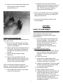
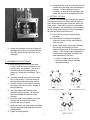
1
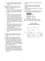
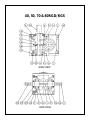
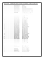
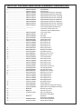
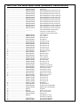
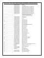
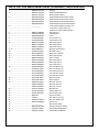
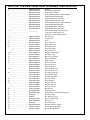
SERVICE MANUAL
MINIATURE RGD/RGS INDEX DRIVES
MODELS
40, 50, 70, 80 RGD/RGS
WARNING
This is a controlled document. It is your responsibility to deliver this information to the end user of the CAMCO or
FERGUSON product. Failure to deliver this could result in your liability for injury to the user or damage to the
machine. For copies of this manual, call your Customer Service Representative at 800-645-5207
TABLE OF CONTENTS
INTRODUCTION ..............................................................................................................2
WARNINGS AND CAUTIONS .........................................................................................2
OIL SEAL REMOVAL .......................................................................................................2
SPARE PARTS KIT ..........................................................................................................2
DISASSEMBLY ................................................................................................................3
REMOVAL OF OUTPUT SHAFT .....................................................................................3
INSPECTION OF CAM FOLLOWERS .............................................................................3
FOLLOWER REMOVAL ...................................................................................................3
REMOVAL OF BEARINGS ..............................................................................................3
INPUT SHAFT/ CAM REMOVAL .....................................................................................4
ASSEMBLY ......................................................................................................................4
PRIOR TO REASSEMBLY ...............................................................................................4
ASSEMBLING INPUT SHAFT .........................................................................................4
ASSEMBLING OUTPUT SHAFT .....................................................................................5
SETTING CAM .................................................................................................................5
HOW TO ORDER PARTS ................................................................................................7
BALLOONED PARTS DRAWINGS ..................................................................................8
PARTS LIST .....................................................................................................................9
1
INTRODUCTION
This service manual pertains to the disassembly and assembly of CAMCO’s Miniature RGD Series Index
Drives MODELS 40, 50, 70 & 80RGD/RGS.
The manual is to be used in conjunction with the General Service Manual which describes the lubrication and
general maintenance of CAMCO Index Drives.
For your convenience in identifying and ordering spare or replacement parts, a complete Bill of Materials is
included in this manual.
Some users of Index Drives have the facilities and trained personnel to accomplish service repair. You must
determine the extent to which intricate servicing should be done in your facility. When in doubt, CAMCO
recommends that CAMCO trained servicemen make the repairs.
WARNINGS AND CAUTIONS
Statements in this manual proceeded by the words WARNING or CAUTION and printed in italics are very
important. We recommend you take special notice of these during service or repair.
WARNING
Means there is the possibility of personal injury to yourself or others.
CAUTION
Means there is the possibility of damage to the CAMCO unit.
OIL SEAL REMOVAL
The only repair possible without disassembly of the indexer is replacement of oil seals. To remove oil seals, drill
a number of holes into the case of the seal. The seal may then be removed with a pointed tool. Be sure to
remove all metallic chips created during the drilling of removal holes. A new seal may be installed as outlined in
the “Oil Seal Installation Recommendations” section of the “General Service Manual”.
SPARE PARTS KIT
CAMCO offers a Spare Parts Kit for all CAMCO index drive models CAMCO builds. These kits include oil seals,
bearings, shims and cam followers. These are components that will most likely require replacement during
repair of your index drive. CAMCO recommends a Spare Parts Kit be purchased and kept on hand prior to any
disassembly of your CAMCO drive.
A complete list of components supplied in the Spare Parts Kit can be found in the parts list located in the rear
of this manual. The asterisk behind the item number indicates those parts supplied with the Spare Parts Kit.
BEFORE STARTING
Before starting disassembly of your CAMCO unit you should read and review the following instructions. These
provide important information on parts and procedures necessary to successfully complete your repair.
Comply with all Warnings and Cautions.
Read the “Trouble Shooting Guide” section of your “General Service Manual” before disassembling CAMCO
units. CAMCO recommends returning defective equipment for inspection and repair whenever possible.
CAMCO uses Loctite to secure all screws and setscrews. If you encounter a fastener that is difficult to remove,
apply heat to the screw and remove while still warm.
2
looseness. It should not exceed .001 inch.Do
not confuse radial loosness with axial endplay.
Endplay will be from .03 to .06 as a normal
condition. If it exceeds .06 it may require
follower replacement.
DISASSEMBLY
1. Remove all accessory equipment such as
clutches, reducers, sprockets, etc.
2. Drain oil and flush with flushing solvent. Retain
any chips or broken pieces that you may find.
These may aid in diagnosis.
3. Remove round access cover. This may be done
by drilling a hole in the cover, threading in a
sheet metal screw, and pulling with pliers.
4. REMOVAL OF OUTPUT SHAFT.
A. Rotate the input shaft until the output is in
dwell.
B. Remove all upper and lower output bearing
cartridge capscrews.
NOTE: Generally, followers are replaced as added
insurance against eventual failure.
6. REPLACEMENT OF CAM FOLLOWERS.
Follower replacement in the field is not
recommended by CAMCO. All follower removal
and replacement must be done at CAMCO. Simply
follow “RETURN FOR REPAIR” instructions in the
“General Service Manual”. CAMCO will provide
quick turnaround on standard follower replacement
or standard follower wheel/shaft assembly
replacement.
C. Remove the upper and lower output
cartridge capscrews.
This is due to the size of the followers and the tools
required to properly remove and install without
damage to the follower stud or follower wheel.
NOTE: Keep the shims with the cartridge. You will
be asked to reinstall or replace with same shim
thickness during assembly.
D. Pull the output bearing thru the cartridge
opening. It may be necessary to tap on the
lower end of the output shaft with a soft
faced hammer to drive the output shaft and
bearing cup out.
7. REMOVAL OF BEARINGS.
A. Remove the output bearing cones from the
output shaft using a small diameter
aluminum bar and hammer. Place the bar
against the protruding edge of the cone and
tap with hammer, working around the
perimeter to prevent binding. Continue this
until the cone is free of shaft.
5. INSPECTION OF CAM FOLLOWERS.
Inspect followers for damage or radial
3
F. Support the side of the cam where the
bearing was removed and press or drive the
shaft through from the remaining bearing
side. This will remove the remaining
bearing and cam simultaneously.
B. Remove any remaining output bearing from
the housing by the same method as
described in step “A”.
9. Remove input bearing cups from the cartridges
with a wheel puller, by prying or by drilling and
tapping for jack screws.
10. Press out all oil seals from both input and
output cartridges.
ASSEMBLY
PRIOR TO REASSEMBLY
Clean and deburr all parts before reassembly.
Follow tightening torque and Loc-tite™
recommendations as outlined in the General
Service Manual.
8. INPUT SHAFT/CAM REMOVAL.
1. Use an arbor press to press bearing cups
into input cartridges. Coat outside of cup
and the cartridge bore with anti-sieze
lubricant prior to pressing. Fill cavity of
cartridges with bearing grease
recommended in the “General Service
Manual”.
NOTE: The output shaft must be removed prior to
input shaft removal.
A. Rotate the input shaft and inspect all parts
for wear or damage. Endplay in the input
shaft is not permissible.
B. Match mark both input cartridges relative to
the housing. These must be reinstalled in
the same side and position since they are
eccentric.
2. ASSEMBLING INPUT SHAFT.
A. Use arbor to press cam onto shaft. Be sure
key is installed into shaft. Apply anti-seize
lubricant on shaft and cam bore prior to
pressing.
C. Remove all input bearing cartridge
capscrews.
B. Center cam on shaft.
D. Tap on end of input shaft to drive the
opposite cartridge from the housing. Then
drive the shaft in the opposite direction for
removal of the remaining cartridge.
C. Use an arbor to press bearing cones
ontoshaft. Coat shaft and bearing bore with
anti-sieze lubricant prior to pressing.
D. Install the input cartridges. Be sure to install
the same exact shims or equivalent height
as removed during disassembly.
NOTE: Keep the shims with their respective
cartriges. You will be asked to reinstall or replace
the same shim thickness during reassembly.
E. Line up match marks.
F. Tighten cartridge mounting screws.
G. If endplay exists remove an equal amount of
shims from each side until there is a small
amount of drag (1 to 2 inch ozs.) from
preloading the bearings. In rare instances it
may be necessary to remachine the
cartridges if all shims have been removed
and endplay still exists.
E. Use a wheel puller to remove one bearing
cone from the input shaft.
4
H. If endplay exists, remove shims until there is
a small amount of drag from preloading the
bearings. In rare instances it may be
necessary to remachine the cartridges if all
shims are removed and endplay still exists.
4. SETTING THE CAM
CAUTION: This mechanism is designed to operate
with adjacent followers in close ontact along their
entire width with the surface of the cam during the
dwell period. Unless this condition is achieved by
proper installation, the mechanism will not transmit
its rated load, and furthermove, serious damage to
the cam and output shaft will occur.
A. Place the cam in dwell (Keyway facing
rearward).
B. Rotate the tops of both input cartridges
toward the output until the cam followers
touch the cam.
C. Shift the cam axially (using shims between
the housing and cartridge) until two
adjacent followers are in full contact with the
cam rib. (This will also require adjustment
to the eccentric cartridges along with the
axial adjustment of the cam).
H. Loosen the cartridge screws and rotate the
cartridge tops to the most rearward position
attainable within the slots provided in the
cartridges.
1.) If there is a gap at the root of the
follower the cam should be shifted
toward the follower.
3. ASSEMBLING OUTPUT SHAFT
A. Install bearing cones on the output shaft.
Coat the shaft and bore with an anti-sieze
lubricant prior to installation. The bore of
the bearing should be heated prior to
pressing, if a heat gun is available. Tap in
place.
B. Install the bearing cup in the lower output
bore of the housing. Coat bore and cup
with anti-sieze lubricant and tap in place.
C. Position the cam so the dwell rib is facing
the output end of the housing. (Keyways
facing rearward.)
D. Insert the output shaft/follower wheel
assembly into the housing. Be sure the
followers straddle the dwell rib during
insertion.
E. Install the upper output bearing cup in the
housing and the cup with anti-sieze
lubricant and tap into place.
F. Install both lower and upper output cartridges
with the equivalent shim thickness removed
in disassembly.
G. Tighten mounting screws.
5
2.) If there is a gap at the tip of the follower
the cam should be shifted away from the
follower.
5. Install a new access cover.Press in flush with
housing.
6. Grease pack the main output bearing with
lubricant specified in the “General Service
Manual”.
D. Apply “Prussian Blue” to entire cam track.
E. Rotate the cam shaft slowly with a small
handrank to ensure that:
7. Install new oil seals as described in the “General
Service Manual”.
1.) Both rollers are in contact with the cam rib
in dwell. Look for uniform bluing pattern.
8. Fill with lubricant recommended in the “General
Service Manual”. (See oil capacities below)
2.) The follower is free at center of crossover
track.
Oil Capacities
3.) You do not encounter unusual resistance
in motion. The bluing pattern should be
fairly uniform from side to side during
motion. If a patch of blueing is worn off the
outside of the cam rib on one side of the
cam and not the other, shift the cam .002
to .005 inches in the direction of the worn
side. Do not overshift the cam or knocking
will occur.
4.) The cam bluing should never be worn off
the leading or exit edges of the cam ribs.
If so this is an indication that the cam is
not adjusted properly.
40RGD/RDS = 6 oz.
50RGD/RGS = 16 oz.
70RGD/RGS = 20—24 oz.
80RGD/RGS = 30—38 oz.
CAUTION: Be sure to add the amount shown
above. Too low a level may result in unit failure.
40, 50, 70 & 80
OIL LEVEL CAPACITIES
5.) There should be no looseness in any
dwell. If there is, adjust the eccentric input
cartridges to slightly preload the loosest
dwell.
Fill Oil to
Center of
Input Shaft.
F. Tighten the input cartridge capscrews and
scribe new match marks on cartridge and
housing.
G. Double check for endplay in output shaft.
Endplay is not permissible in output shaft.
H. Remove the input cartridges (one at a time)
and coat the surface between the shims and
the housing with “General Electric Silicone
Rubber RTV-6” (to insure against leakage) and
reinstall, aligning the match marks, tighten the
screws and dowel in place.
I. Remove the output cartridges (one at a time)
and coat the surface between the shims and
the housing with “General Electric Silicone
Rubber RTV-6” (to insure against leakage and
reinstall, aligning the match marks and tighten
the screws.
6
HOW TO ORDER PARTS
Please refer to parts list shown in this manual. This parts list is for a standard Index Drive. If you feel your drive
is nonstandard or you are in doubt you should contact CAMCO Customer Service at (847) 459-5200 and
request a Bill of Material for your specific unit based on serial number. CAMCO maintains records on all units
for a period of ten years.
You may order parts per the standard Bill of Material even if your unit is nonstandard. CAMCO’s order entry
people will review the closed order file based on the following information and supply you with the correct part.
REQUIRED INFORMATION
1. Original purchase order number (if available)
2. Customer name (original purchaser of drive)
3. Model number (located on name plate)
4. Serial number (located on name plate)
5. Approximate date of purchase.
TO ORDER PARTS contact CAMCO “Order Entry Department” Wheeling, Illinois
Phone (847) 459-5200 or Fax (847) 459-3064
A. Describe the parts required and the 14 digit part number as listed in the Standard Bill of Materials or a
Special Bill of Materials pertaining to your unit. State if you are using a Standard or Special bill of
material.
B. Give as much of the above required information as possible.
ON WARRANTY
Replacement parts CAMCO will send freight prepaid via most practical means.
CAMCO will issue a “Returned Material Authorization Number” (RMA#) for the return of defective parts for
inspection. CAMCO will bill customer for repair parts. When inspection of returned parts has been completed
and determined to be a warranty problem, CAMCO will issue a credit to the customer for the repair parts and
freight charges.
ON NON-WARRANTY
Replacement or spare parts, with approved credit, are F.O.B. our plant Wheeling, Illinois.
7
40, 50, 70 & 80RGD/RGS
SIDE VIEW
END VIEW
8
PARTS LIST FOR 40RGD INDEX DRIVE (STANDARD CONFIGURATION)
1 ...................................................... 4MD55426001002
2 ...................................................... 4MB51870007002
........................................................ 4MA49071007001
3 ...................................................... 4MB51609004006
........................................................ 4MB51610004008
........................................................ 4MB51611004010
........................................................ 4MB51612004012
4 ...................................................... ___________
........................................................
........................................................
5 ...................................................... 4MB51655003002
6 ...................................................... 4MB51874003001
7 ...................................................... 4MA51903000000
8 ...................................................... 95A51910300000
9 ...................................................... 84D07329470000
10 .................................................... 4MA51916018800
........................................................ 4MA51916028800
........................................................ 4MA51916038800
........................................................ 4MA51916048800
11 .................................................... 86D07328270022
12 .................................................... 86D07328270021
13 .................................................... 95A51910300000
14 .................................................... 86D07328090021
15 .................................................... 86D07328090022
16 .................................................... 4MA51652003002
17 .................................................... 4MA51915018800
........................................................ 4MA51915028800
........................................................ 4MA51915038800
........................................................ 4MA51915048800
18 .................................................... 95A33042030000
19 .................................................... 82A49589000000
........................................................ 82A49590000000
20 .................................................... 86D07328120021
21 .................................................... 86D07328120022
22 .................................................... 4MA51914018800
........................................................ 4MA51914028800
........................................................ 4MA51914038800
........................................................ 4MA51914048800
23 .................................................... 95A51911070000
24 .................................................... 84D07329480000
25 .................................................... 84D07329540000
26 .................................................... M04K088
27 .................................................... M06K108
28 .................................................... 95A33002140000
29 .................................................... __________
30 .................................................... ____________
31 .................................................... __________
32 .................................................... 99A44547180000
33 .................................................... 99A44547010000
Housing
Input Shaft Dbl
Input Shaft Sgl
Output Shaft/Foll Whl 6 Hole 3/8 Foll
Output Shaft/Foll Whl 8 Hole 3/8 Foll
Output Shaft/Foll Whl 10 Hole 1/4 Foll
Output Shaft/Foll Whl 12 Hole 1/4 Foll
“Cam, (Specify Number Of Stops And “
“Index Time, Contact Camco For “
“Assistance, Order In Matched Sets)”
“Cart, Output Large “
“Cart, Input”
Bore Plug
Shcs M4 X 10mm Lg.
Oil Seal C/R 13534
Shim Outp Lg .002
Shim Outp Lg .005
Shim Outp Lg .010
Shim Outp Lg .003
Bearing Cup L68111
Bearing Cone L68149
Shcs M4 X 10mm Lg.
Bearing Cone Lm 12749
Bearing Cup Lm12711
“Cart, Output Small “
Shim Outp Sm .002
Shim Outp Sm .005
Shim Outp Sm .010
Shim Outp Sm .003
Sss M 3 X 5 Lg (Cone Pt)
Cam Follower 3/8 Dia.
Cam Follower 1/4 Dia.
Bearing Cone Lm11949
Bearing Cup Lm11910
Shim 40rgd Inp .002
Shim 40rgd Inp .005
Shim 40rgd Inp .010
Shim 40rgd Inp .003
Bhcs M4 X 10mm Lg.
Oil Seal C/R 7440
Oil Seal C/R 8017
Key 4mm Xq X .88 Lg
Key 6mm Sq X 1.08
Plug .12-27 Npt Flush
Not Used On 40 Rgd/Rgs
Not Used On 40 Rgd
Not Used On 40 Rgd/Rgs
Service Manual Miniatures
General Service Manual
9
PARTS LIST FOR 40RGS INDEX DRIVE (STANDARD CONFIGURATION)
1 ...................................................... 4MD55426001002
2 ...................................................... 4MB51870007002
........................................................ 4MA49071007001
3 ...................................................... 4MB51614004006
........................................................ 4MB51615004008
........................................................ 4MB51616004010
........................................................ 4MB51617004012
........................................................ 4MB51899004006
........................................................ 4MB51900004008
........................................................ 4MB51901004010
........................................................ 4MB51902004012
4 ...................................................... ___________
........................................................
........................................................
5 ...................................................... 4MB51655003002
6 ...................................................... 4MB51874003001
7 ...................................................... 4MA51903000000
8 ...................................................... 95A51910300000
9 ...................................................... 84D07329470000
10 .................................................... 4MA51916018800
........................................................ 4MA51916028800
........................................................ 4MA51916038800
........................................................ 4MA51916048800
11 .................................................... 86D07328270022
12 .................................................... 86D07328270021
13 .................................................... 95A51910300000
14 .................................................... 86D07328090021
15 .................................................... 86D07328090022
16 .................................................... 4MA51652003002
17 .................................................... 4MA51915018800
........................................................ 4MA51915028800
........................................................ 4MA51915038800
........................................................ 4MA51915048800
18 .................................................... 95A33042030000
19 .................................................... 82A49589000000
........................................................ 82A49590000000
20 .................................................... 86D07328120021
21 .................................................... 86D07328120022
22 .................................................... 4MA51914018800
........................................................ 4MA51914028800
........................................................ 4MA51914038800
........................................................ 4MA51914048800
23 .................................................... 95A51911070000
24 .................................................... 84D07329480000
25 .................................................... 84D07329540000
........................................................ 4MA51904000000
26 .................................................... M04K088
27 .................................................... M06K108
28 .................................................... 95A33002140000
29 .................................................... __________
30 .................................................... M05K125
31 .................................................... __________
32 .................................................... 99A44547180000
33 .................................................... 99A44547010000
Housing
Input Shaft Dbl
Input Shaft Sgl
Output Shaft/Foll Whl 6 Hole 3/8 Dia Sgl
Output Shaft/Foll Whl 8 Hole 3/8 Dia Sgl
Output Shaft/Foll Whl 10 Hole 1/4 Dia Sgl
Output Shaft/Foll Whl 12 Hole 1/4 Dia Sgl
Output Shaft/Foll Whl 6 Hole 3/8 Dia Dbl
Output Shaft/Foll Whl 8 Hole 3/8 Dia Dbl
Output Shaft/Foll Whl 10 Hole 1/4 Dia Dbl
Output Shaft/Foll Whl 12 Hole 1/4 Dia Dbl
“Cam, (Specify Number Of Stops And “
“Index Time, Contact Camco For “
“Assistance, Order In Matched Sets)”
“Cart, Output Large “
“Cart, Input”
Bore Plug
Shcs M4 X 10mm Lg.
Oil Seal C/R 13534
Shim Outp Lg .002
Shim Outp Lg .005
Shim Outp Lg .010
Shim Outp Lg .003
Bearing Cup L68111
Bearing Cone L68149
Shcs M4 X 10mm Lg.
Bearing Cone Lm 12749
Bearing Cup Lm12711
“Cart, Output Small “
Shim Outp Sm .002
Shim Outp Sm .005
Shim Outp Sm .010
Shim Outp Sm .003
Sss M 3 X 5 Lg (Cone Pt)
Cam Follower 3/8 Dia.
Cam Follower 1/4 Dia.
Bearing Cone Lm11949
Bearing Cup Lm11910
Shim 40rgd Inp .002
Shim 40rgd Inp .005
Shim 40rgd Inp .010
Shim 40rgd Inp .003
Bhcs M4 X 10mm Lg.
Oil Seal C/R 7440
Oil Seal C/R 8017 (FOR DBL OUTPUT)
BORE PLUG 1.250 (FOR SGL OUTPUT)
Key 4mm Xq X .88 Lg
Key 6mm Sq X 1.08
Plug .12-27 Npt Flush
Not Used On 40 Rgd/Rgs
Key Metric
Not Used On 40 Rgd/Rgs
Service Manual Miniatures
General Service Manual
10
PARTS LIST FOR 50RGD INDEX DRIVE (STANDARD CONFIGURATION)
1 ...................................................... 5MD55427001002
2 ...................................................... 5MC52018007002
3 ...................................................... 5MC52026004006
........................................................ 5MC52027004006
........................................................ 5MC52025004008
........................................................ 5MC52023004010
........................................................ 5MC52024004010
........................................................ 5MC51673004012
4 ...................................................... ___________
........................................................
........................................................
5 ...................................................... 5MB52029003002
6 ...................................................... 5MB52019003002
7 ...................................................... 5MA52057000000
8 ...................................................... 95A33040030000
9 ...................................................... 84D07329560000
10 .................................................... 5MA52009018800
........................................................ 5MA52009028800
........................................................ 5MA52009038800
........................................................ 5MA52009048800
11 .................................................... 86D07328390022
12 .................................................... 86D07328390021
13 .................................................... 95A33040030000
14 .................................................... 86D07328200021
15 .................................................... 86D07328200022
* ....................................................... 5MB52020003002
17 .................................................... 5MA52010018800
........................................................ 5MA52010028800
........................................................ 5MA52010038800
........................................................ 5MA52010048800
18 .................................................... 95A33042120000
........................................................ 95A33042050000
19 .................................................... 82A49590000000
........................................................ 82A49591000000
........................................................ 82A49592000000
20 .................................................... 86D07328120021
21 .................................................... 86D07328120022
22 .................................................... 5MA52011018800
........................................................ 5MA52011028800
........................................................ 5MA52011038800
........................................................ 5MA52011048800
23 .................................................... 95A51911110000
24 .................................................... 84D07329480000
25 .................................................... 84D07329550000
26 .................................................... M05K125
27 .................................................... M08K138
28 .................................................... 95A33002140000
29 .................................................... 5MA52182000000
30 .................................................... ___________
31 .................................................... ___________
32 .................................................... 99A44547180000
33 .................................................... 99A44547010000
Housing
“Shaft, Input”
Output Shaft/Foll Whl 6 Hole 7/16 Dia.
Output Shaft/Foll Whl 6 Hole 9/16 Dia.
Output Shaft/Foll Whl 8 Hole 7/16 Dia.
Output Shaft/Foll Whl 10 Hole 1/4 Dia.
Output Shaft/Foll Whl 10 Hole 7/16 Dia.
Output Shaft/Foll Whl 12 Hole 1/4 Dia.
“Cam, (Specify Number Of Stops And “
“Index Time, Contact Camco For “
“Assistance, Order In Matched Sets)”
“Cart, Output Lg”
“Cart, Input Ecc “
Bore Plug 2.756
Shcs M5 X 10
Oil Seal C/R 17754
Shim Outp .002 Tk
Shim Outp .005 Tk
Shim Outp .010 Tk
Shim Outp .003 Tk
Brg Cup Lm102910
Brg Cone Lm 102949
Shcs M5 X 10
Brg Cone L45449
Brg Cup L45410
“Cart, Output Sm “
Shim Outp .002 Tk
Shim Outp .005tk
Shim Outp .010 Tk
Shim Outp .003 Tk
Sss M4 X 8 Lg Cone Point
Sss M3 X 8 Lg Cone Point
Cam Follower 1/4 Dia
Cam Follower 7/16 Dia
Cam Follower 9/16 Dia
Bearing Cone Lm11949
Bearing Cup Lm11910
Shim Inp .002 Tk
Shim Inp .005 Tk
Shim Inp .010 Tk
Shim Inp .003 Tk
Bhcs M5 X 12
Oil Seal C/R 7440
Oil Seal C/R 11067
Key Metric
Key 8 X 7mm X 1.38 Lg
Plug .12-27 Npt Flush
“Spacer, Cam “
Not Used On 50 Rgd
Not Used On 50 Rgd/rgs
Service Manual Miniatures
General Service Manual
11
PARTS LIST FOR 50RGS INDEX DRIVE (STANDARD CONFIGURATION)
1 ........................................................... 5MD55427001002
2 ........................................................... 5MC52018007002
............................................................. 5MC52041004006
............................................................. 5MC52040004006
............................................................. 5MC52039004008
............................................................. 5MC52038004010
............................................................. 5MC52037004010
............................................................. 5MC52042004012
............................................................. 5MC52050004006
............................................................. 5MC52049004006
............................................................. 5MC52048004008
............................................................. 5MC52047004010
............................................................. 5MC52046004010
............................................................. 5MC52051004012
4 ........................................................... ___________
.............................................................
.............................................................
5 ........................................................... 5MB52029003002
6 ........................................................... 5MB52019003002
7 ........................................................... 5MA52057000000
8 ........................................................... 95A33040030000
9 ........................................................... 84D07329560000
10 ......................................................... 5MA52009018800
............................................................. 5MA52009028800
............................................................. 5MA52009038800
............................................................. 5MA52009048800
11 ......................................................... 86D07328390022
12 ......................................................... 86D07328390021
13 ......................................................... 95A33040030000
14 ......................................................... 86D07328200021
15 ......................................................... 86D07328200022
* ............................................................ 5MB52020003002
17 ......................................................... 5MA52010018800
............................................................. 5MA52010028800
............................................................. 5MA52010038800
............................................................. 5MA52010048800
18 ......................................................... 95A33042120000
............................................................. 95A33042050000
19 ......................................................... 82A49590000000
............................................................. 82A49591000000
............................................................. 82A49592000000
20 ......................................................... 86D07328120021
21 ......................................................... 86D07328120022
22 ......................................................... 5MA52011018800
............................................................. 5MA52011028800
............................................................. 5MA52011038800
............................................................. 5MA52011048800
23 ......................................................... 95A51911110000
24 ......................................................... 84D07329480000
25 ......................................................... 84D07329550000
............................................................. 5MA52057000000
26 ......................................................... M05K125
27 ......................................................... M08K138
28 ......................................................... 95A33002140000
29 ......................................................... 5MA52182000000
30 ......................................................... M06K162
31 ......................................................... ___________
32 ......................................................... 99A44547180000
33 ......................................................... 99A44547010000
Housing
“Shaft, Input”
Output Shaft/Foll Whl 6 Hole 9/16 Dia. Sgl
Output Shaft/Foll Whl 6 Hole 7/16 Dia. Sgl
Output Shaft/Foll Whl 8 Hole 7/16 Dia. Sgl
Output Shaft/Foll Whl 10 Hole 7/16 Dia. Sgl
Output Shaft/Foll Whl 10 Hole 1/4 Dia. Sgl
Output Shaft/Foll Whl 12 Hole 1/4 Dia. Sgl
Output Shaft/Foll Whl 6 Hole 9/16 Dia. Dbl
Output Shaft/Foll Whl 6 Hole 7/16 Dia. Dbl
Output Shaft/Foll Whl 8 Hole 7/16 Dia. Dbl
Output Shaft/Foll Whl 10 Hole 7/16 Dia. Dbl
Output Shaft/Foll Whl 10 Hole 1/4 Dia. Dbl
Output Shaft/Foll Whl 12 Hole 1/4 Dia. Dbl
“Cam, (Specify Number Of Stops And “
“Index Time, Contact Camco For “
“Assistance, Order In Matched Sets)”
“Cart, Output Lg”
“Cart, Input Ecc “
Bore Plug 2.756
Shcs M5 X 10
Oil Seal C/R 17754
Shim Outp .002 Tk
Shim Outp .005 Tk
Shim Outp .010 Tk
Shim Outp .003 Tk
Brg Cup Lm102910
Brg Cone Lm 102949
Shcs M5 X 10
Brg Cone L45449
Brg Cup L45410
“Cart, Output Sm “
Shim Outp .002 Tk
Shim Outp .005tk
Shim Outp .010 Tk
Shim Outp .003 Tk
Sss M4 X 8 Lg Cone Point
Sss M3 X 8 Lg Cone Point
Cam Follower 1/4 Dia
Cam Follower 7/16 Dia
Cam Follower 9/16 Dia
Bearing Cone Lm11949
Bearing Cup Lm11910
Shim Inp .002 Tk
Shim Inp .005 Tk
Shim Inp .010 Tk
Shim Inp .003 Tk
Bhcs M5 X 12
Oil Seal C/R 7440
Oil Seal C/R 11067 (FOR DBL)
BORE PLUG 2.756 (FOR SGL)
Key Metric
Key 8 X 7mm X 1.38 Lg
Plug .12-27 Npt Flush
“Spacer, Cam “
KEY 6MM SQ X 1.62 LG
Not Used On 50 Rgd/rgs
Service Manual Miniatures
General Service Manual
12
PARTS LIST FOR 70RGD INDEX DRIVE (STANDARD CONFIGURATION)
1 ...................................................... 7MG60152001002
2 ...................................................... 7MB60190007002
3 ...................................................... 7MB60253004006
........................................................ 7MB60254004006
........................................................ 7MB60255004008
........................................................ 7MB60256004010
........................................................ 7MB60268004012
4 ...................................................... ___________
........................................................
........................................................
5 ...................................................... 7MB60176003002
6 ...................................................... 7MB60164003002
7 ...................................................... 7MB60194002002
8 ...................................................... 95A33040040000
9 ...................................................... 84C60165030000
10 .................................................... 7MA60180018800
........................................................ 7MA60180028800
........................................................ 7MA60180038800
11-12 ............................................... 86D07328560013
13 .................................................... 95A33040040000
14 .................................................... 86D07328170021
15 .................................................... 86D07328170022
16 .................................................... 7MB60177003002
17 .................................................... 7MA60181018800
........................................................ 7MA60181028800
........................................................ 7MA60181038800
18 .................................................... 95A33042140000
........................................................ 95A33042220000
19 .................................................... 82A49591000000
........................................................ 82C33150010003
........................................................ 82C33150020003
20 .................................................... 86D07328230021
21 .................................................... 86D07328230022
22 .................................................... 26B01052018800
........................................................ 26B01052028800
........................................................ 26B01052038800
23 .................................................... 95A51911100000
24 .................................................... 84C60165010000
25 .................................................... 84C60165020000
26 .................................................... M06K150
27 .................................................... 025K187
28 .................................................... 95A33002130000
29 .................................................... 7MA60192009000
30 .................................................... ______________
31 .................................................... ______________
32 .................................................... 99A44547180000
33 .................................................... 99A44547010000
Housing
“Shaft, Input”
Output Shaft/Foll Whl 6 Hole 3/4 Dia.
Output Shaft/Foll Whl 6 Hole 5/8 Dia.
Output Shaft/Foll Whl 8 Hole 5/8 Dia.
Output Shaft/Foll Whl 10 Hole 5/8 Dia.
Output Shaft/Foll Whl 12 Hole 7/16 Dia.
“Cam, (Specify Number Of Stops And “
“Index Time, Contact Camco For “
“Assistance, Order In Matched Sets)”
Cap Output Lg
Cart Input Ecc
Cover
S.H.C.S. M5 X 12
Oil Seal C/R 25420
Shim Outp .002 Tk
Shim Outp .005 Tk
Shim Outp .010 Tk
BRG ASSY TIMKEN 32013X 90KA1
S.H.C.S. M5 X 12
Brg Cone 07100
Brg Cup 07196
Cap Output Sm
Shim Outp Sm .002
Shim Outp Sm .005
Shim Outp Sm .010
Sss Cone Pt M4x12
Sss Cone Pt M5 X 12 Lg
Follower 7/32 Dia.
Follower 5/8 Dia.
Follower 3/4 Dia.
Brg Cone Timken Lm 67048
Brg Cup Timken Lm 67010
Shim Inp .002 Thk
Shim Inp .005 Thk
Shim Inp .010 Thk
Bhcs M5 X 10 Lg
Oil Seal C/R 9715
Oil Seal C/R 11610
Key 6mm Sq X 1.50 Lg F.S.
Key .250 Sq. X 1.87 F.S.
Plug .25-18 Npt Flush
Spacer Cam
Not Used On 70rgd
Not Used On 70rgd/rgs
Service Manual Miniatures
General Service Manual
13
PARTS LIST FOR 70RGS INDEX DRIVE (STANDARD CONFIGURATION)
1 ...................................................... 7MG60152001002
2 ...................................................... 7MB60190007002
3 ...................................................... 7MB60257004006
........................................................ 7MB60258004006
........................................................ 7MB60259004008
........................................................ 7MB60260004010
........................................................ 7MB60262004006
........................................................ 7MB60263004006
........................................................ 7MB60264004008
........................................................ 7MB60265004010
4 ...................................................... ___________
........................................................
........................................................
5 ...................................................... 7MB60176003002
6 ...................................................... 7MB60164003002
7 ...................................................... 7MB60194002002
8 ...................................................... 95A33040040000
9 ...................................................... 84C60165030000
10 .................................................... 7MA60180018800
........................................................ 7MA60180028800
........................................................ 7MA60180038800
11-12 ............................................... 86D07328560013
13 .................................................... 95A33040040000
14 .................................................... 86D07328170021
15 .................................................... 86D07328170022
16 .................................................... 7MB60177003002
17 .................................................... 7MA60181018800
........................................................ 7MA60181028800
........................................................ 7MA60181038800
18 .................................................... 95A33042140000
........................................................ 95A33042220000
19 .................................................... 82A49591000000
........................................................ 82C33150010003
........................................................ 82C33150020003
20 .................................................... 86D07328230021
21 .................................................... 86D07328230022
22 .................................................... 26B01052018800
........................................................ 26B01052028800
........................................................ 26B01052038800
23 .................................................... 95A51911100000
24 .................................................... 84C60165010000
25 .................................................... 84C60165020000
26 .................................................... M06K150
27 .................................................... 025K187
28 .................................................... 95A33002130000
29 .................................................... 7MA60192009000
30 .................................................... M08K200
31 .................................................... ______________
32 .................................................... 99A44547180000
33 .................................................... 99A44547010000
Housing
“Shaft, Input”
Output Shaft/Foll Whl 6 Hole 3/4 Dia. Sgl
Output Shaft/Foll Whl 6 Hole 5/8 Dia. Sgl
Output Shaft/Foll Whl 8 Hole 5/8 Dia. Sgl
Output Shaft/Foll Whl 10 Hole 5/8 Dia. Sgl
Output Shaft/Foll Whl 6 Hole 3/4 Dia. Dbl
Output Shaft/Foll Whl 6 Hole 5/8 Dia. Dbl
Output Shaft/Foll Whl 8 Hole 5/8 Dia. Dbl
Output Shaft/Foll Whl 10 Hole 5/8 Dia. Dbl
“Cam, (Specify Number Of Stops And “
“Index Time, Contact Camco For “
“Assistance, Order In Matched Sets)”
Cap Output Lg
Cart Input Ecc
Cover
S.H.C.S. M5 X 12
Oil Seal C/R 25420
Shim Outp .002 Tk
Shim Outp .005 Tk
Shim Outp .010 Tk
BRG ASSY TIMKEN 32013X 90KA1
S.H.C.S. M5 X 12
Brg Cone 07100
Brg Cup 07196
Cap Output Sm
Shim Outp Sm .002
Shim Outp Sm .005
Shim Outp Sm .010
Sss Cone Pt M4x12
Sss Cone Pt M5 X 12 Lg
Follower 7/32 Dia.
Follower 5/8 Dia.
Follower 3/4 Dia.
Brg Cone Timken Lm 67048
Brg Cup Timken Lm 67010
Shim Inp .002 Thk
Shim Inp .005 Thk
Shim Inp .010 Thk
Bhcs M5 X 10 Lg
Oil Seal C/R 9715
Oil Seal C/R 11610 (FOR DBL OUTPUT ONLY)
Key 6mm Sq X 1.50 Lg F.S.
Key .250 Sq. X 1.87 F.S.
Plug .25-18 Npt Flush
Spacer Cam
KEY 8X7MM X2LG
Not Used On 70rgd/rgs
Service Manual Miniatures
General Service Manual
14
PARTS LIST FOR 80RGD INDEX DRIVE (STANDARD CONFIGURATION)
1 ...................................................... 8MG60210001002
2 ...................................................... 8MB60757007002
........................................................ 8MC60917007002
3 ...................................................... 8MC60827004006
........................................................ 8MC60828004008
........................................................ 8MC60829004010
........................................................ 8MC60830004012
4 ...................................................... ___________
........................................................
........................................................
5 ...................................................... 8MB60772003002
6 ...................................................... 7MB60164003002
7 ...................................................... 8MA63280002002
8 ...................................................... 95A33040040000
9 ...................................................... 84C60165040000
10 .................................................... 8MB60776018800
........................................................ 8MB60776028800
........................................................ 8MB60776038800
11-12 ............................................... 86D07328650013
13 .................................................... 95A33004180000
14 .................................................... 86D07328350021
15 .................................................... 86D07328350022
16 .................................................... 8MB60764003002
17 .................................................... 8MA60768018800
........................................................ 8MA60768028800
........................................................ 8MA60768038800
18 .................................................... 95A33042230000
........................................................ 95A33042140000
19 .................................................... 82C33150020003
........................................................ 82C33150030003
........................................................ 82C33150010003
20 .................................................... 86D07328170021
21 .................................................... 86D07328170022
22 .................................................... 26B01052018800
........................................................ 26B01052028800
........................................................ 26B01052038800
23 .................................................... 95A51911080000
24 .................................................... 84C60165010000
25 .................................................... 84C60165050000
26 .................................................... M08K200
27 .................................................... 025K212
28 .................................................... 95A33002130000
29 .................................................... 8MA60758009000
30 .................................................... _____________
31 .................................................... 8MC60918009100
32 .................................................... 99A44547180000
33 .................................................... 99A44547010000
Housing
Shaft Input (W/O Reducer)
Shaft Input (For 180sm)
Output Shaft/Foll Whl 6 Holes 7/8 Dia.
Output Shaft/Foll Whl 8 Holes 3/4 Dia.
Output Shaft/Foll Whl 10 Holes 5/8 Dia.
Output Shaft/Foll Whl 12 Holes 9/36 Dia.
“Cam, (Specify Number Of Stops And “
“Index Time, Contact Camco For “
“Assistance, Order In Matched Sets)”
Cap Output Lg
Cart Input Ecc
Cover
S.H.C.S. M5 X 12
Oil Seal C/R 31510
Shim Outp .002 Tk
Shim Outp .005 Tk
Shim Outp .010 Tk
Brg Assy 32016x 92ka1
Shcs M6 X 16 Lg
Brg Cone Lm 501349
Brg Cup Lm501310
Cap Lo Output
Shim Outp .002 Tk
Shim Outp .005 Tk
Shim Outp .010 Tk
Sss Cone Pt M5 X16
Sss Cone Pt M4 X 12
Cam Follower 3/4 Dia.
Cam Follower 7/8 Dia.
Cam Follower 5/8 Dia.
Brg Cone 07100
Brg Cup 07196
Shim Inp .002 Thk
Shim Inp .003 Thk
Shim Inp .010 Thk
Bhcs M4 X12
Oil Seal C/R 9715
Oil Seal C/R 14725
Key 8x7mm X2lg
Key .250sq X 2.12 Lg
Plug .25-18 Npt Flush
Spacer Cam
Not Used On 80rgd
Mounting Plate (For 180sm)
Service Manual Miniatures
General Service Manual
15
PARTS LIST FOR 80RGS INDEX DRIVE (STANDARD CONFIGURATION)
1 ...................................................... 8MG60210001002
2 ...................................................... 8MB60757007002
........................................................ 8MC60917007002
3 ...................................................... 8MC60831004006
........................................................ 8MC60832004006
........................................................ 8MC60833004010
........................................................ 8MC60834004012
........................................................ 8MC60835004006
........................................................ 8MC60836004008
........................................................ 8MC60837004008
........................................................ 8MC60838004012
4 ...................................................... ___________
........................................................
........................................................
5 ...................................................... 8MB60772003002
6 ...................................................... 7MB60164003002
7 ...................................................... 8MA63280002002
8 ...................................................... 95A33040040000
9 ...................................................... 84C60165040000
10 .................................................... 8MB60776018800
........................................................ 8MB60776028800
........................................................ 8MB60776038800
11-12 ............................................... 86D07328650013
13 .................................................... 95A33004180000
14 .................................................... 86D07328350021
15 .................................................... 86D07328350022
16 .................................................... 8MB60764003002
17 .................................................... 8MA60768018800
........................................................ 8MA60768028800
........................................................ 8MA60768038800
18 .................................................... 95A33042230000
........................................................ 95A33042140000
19 .................................................... 82C33150020003
........................................................ 82C33150030003
........................................................ 82C33150010003
20 .................................................... 86D07328170021
21 .................................................... 86D07328170022
22 .................................................... 26B01052018800
........................................................ 26B01052028800
........................................................ 26B01052038800
23 .................................................... 95A51911080000
24 .................................................... 84C60165010000
25 .................................................... 84C60165050000
26 .................................................... M08K200
27 .................................................... 025K212
28 .................................................... 95A33002130000
29 .................................................... 8MA60758009000
30 .................................................... M08K200
31 .................................................... 8MC60918009100
32 .................................................... 99A44547180000
33 .................................................... 99A44547010000
Housing
Shaft Input (W/O Reducer)
Shaft Input (For 180sm)
“Output Shaft/Foll Whl (For 6h24, 6h28) Sgl”
Output Shaft/Foll Whl 8h24 Sgl
Output Shaft/Foll Whl 10h20 Sgl
Output Shaft/Foll Whl 12h18 Sgl
“Output Shaft/Foll Whl (For 6h24, 6h28) Dbl”
Output Shaft/Foll Whl 8h24 Dbl
Output Shaft/Foll Whl 10h20 Dbl
Output Shaft/Foll Whl 12h18 Dbl
“Cam, (Specify Number Of Stops And “
“Index Time, Contact Camco For “
“Assistance, Order In Matched Sets)”
Cap Output Lg
Cart Input Ecc
Cover
S.H.C.S. M5 X 12
Oil Seal C/R 31510
Shim Outp .002 Tk
Shim Outp .005 Tk
Shim Outp .010 Tk
Brg Assy 32016x 92ka1
Shcs M6 X 16 Lg
Brg Cone Lm 501349
Brg Cup Lm501310
Cap Lo Output
Shim Outp .002 Tk
Shim Outp .005 Tk
Shim Outp .010 Tk
Sss Cone Pt M5 X16
Sss Cone Pt M4 X 12
Cam Follower 3/4 Dia.
Cam Follower 7/8 Dia.
Cam Follower 5/8 Dia.
Brg Cone 07100
Brg Cup 07196
Shim Inp .002 Thk
Shim Inp .003 Thk
Shim Inp .010 Thk
Bhcs M4 X12
Oil Seal C/R 9715
Oil Seal C/R 14725 (For Dbl Output Only)
Key 8x7mm X2lg
Key .250sq X 2.12 Lg
Plug .25-18 Npt Flush
Spacer Cam
Key 8x7mm X2lg
Mounting Plate (For 180sm)
Service Manual Miniatures
General Service Manual
16
CAMCO & FERGUSON Products
1444 South Wolf Road
Wheeling, IL 60090
USA
ph: 847-459-5200
toll-free: 800-645-5200
fax: 847-459-3064
[email protected]
DE-STA-CO Europe
Germany
+49-6171-705-0
[email protected]
DE-STA-CO Asia
Thailand
+66-2-326-0812
[email protected]
ISO 9001:2000 Registered
DE-STA-CO Headquarters
Auburn Hills, Michigan USA
248-836-6700
[email protected]
DE-STA-CO South America
Brazil
0800-124070
[email protected]
www.destaco.com
This publication is for information purposes
only and should not be considered a binding
description of the product except is
confirmed in writing by Industrial Motion
Control, LLC/DE-STA-CO
© DE-STA-CO 2004-2014
All rights reserved
Printed in U.S.A.
SKU 0064 (6/99)
99A44547180000


![2.8 conexión de varios servidores xt[2]](http://vs1.manualzilla.com/store/data/006305919_1-9948e093384d4040cdf0f68f445b7f43-150x150.png)