1
SJ-600
SJ-600/500
USER'S MANUAL
This User's Manual is intended for SJ-600 and SJ-500.
Thank you very much for purchasing this machine.
•
To ensure correct and safe usage with a full understanding of this product's performance, please be sure to read through this manual completely and store it in a safe
location.
•
Unauthorized copying or transferral, in whole or in part, of this manual is prohibited.
•
The contents of this operation manual and the specifications of this product are
subject to change without notice.
•
The operation manual and the product have been prepared and tested as much as
possible. If you find any misprint or error, please inform us.
•
Roland DG Corp. assumes no responsibility for any direct or indirect loss or damage
which may occur through use of this product, regardless of any failure to perform on
the part of this product.
•
Roland DG Corp. assumes no responsibility for any direct or indirect loss or damage
which may occur with respect to any article made using this product.
For the USA
FEDERAL COMMUNICATIONS COMMISSION
RADIO FREQUENCY INTERFERENCE
STATEMENT
This equipment has been tested and found to comply with the
limits for a Class A digital device, pursuant to Part 15 of the
FCC Rules.
These limits are designed to provide reasonable protection
against harmful interference when the equipment is operated
in a commercial environment.
This equipment generates, uses, and can radiate radio
frequency energy and, if not installed and used in accordance
with the instruction manual, may cause harmful interference
to radio communications.
Operation of this equipment in a residential area is likely to
cause harmful interference in which case the user will be
required to correct the interference at his own expense.
NOTICE
Grounding Instructions
Do not modify the plug provided - if it will not fit the outlet,
have the proper outlet installed by a qualified electrician.
Check with qualified electrician or service personnel if the
grounding instructions are not completely understood, or if in
doubt as to whether the tool is properly grounded.
Use only 3-wire extension cords that have 3-prong
grounding plugs and 3-pole receptacles that accept the tool’s
plug.
Repair or replace damaged or worn out cord immediately.
Operating Instructions
KEEP WORK AREA CLEAN. Cluttered areas and benches
invites accidents.
Unauthorized changes or modification to this system can void
the users authority to operate this equipment.
DON’T USE IN DANGEROUS ENVIRONMENT. Don’t
use power tools in damp or wet locations, or expose them to
rain. Keep work area well lighted.
DISCONNECT TOOLS before servicing; when changing
accessories, such as blades, bits, cutters, and like.
The I/O cables between this equipment and the computing
device must be shielded.
REDUCE THE RISK OF UNINTENTIONAL STARTING.
Make sure the switch is in off position before plugging in.
USE RECOMMENDED ACCESSORIES. Consult the
owner’s manual for recommended accessories. The use of
improper accessories may cause risk of injury to persons.
NEVER LEAVE TOOL RUNNING UNATTENDED.
TURN POWER OFF. Don’t leave tool until it comes to a
complete stop.
For Canada
CLASS A
NOTICE
This Class A digital apparatus meets all requirements of the
Canadian Interference-Causing Equipment Regulations.
CLASSE A
AVIS
Cet appareil numérique de la classe A respecte toutes les
exigences du Règlement sur le matériel brouilleur du
Canada.
ROLAND DG CORPORATION
1-6-4 Shinmiyakoda, Hamamatsu-shi, Shizuoka-ken, JAPAN 431-2103
MODEL NAME
: See the MODEL given on the rating plate.
RELEVANT DIRECTIVE : EC LOW VOLTAGE DIRECTIVE (73/23/EEC)
EC ELECTROMAGNETIC COMPATIBILITY DIRECTIVE (89/336/EEC)
WARNING
This is a Class A product. In a domestic environment this product may cause radio interference in which
case the user may be required to take adequate measures.
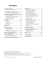
Contents
To Ensure Safe Use ............................... 2
Maintenance ........................................ 39
About the Labels Affixed to the Unit ......................... 6
Replacing the Ink Cartridges .................................. 39
Pour utiliser en toute sécurité ............. 8
À propos des étiquettes collées sur l'appareil ........ 12
Check How Much Ink Remains .............................. 41
Cleaning the Printing Heads ................................... 42
Disposal of Discharged Ink ..................................... 43
What to Do upon Opening the Carton ...14
How to Replace the Separating Knife .................... 44
1 Checking Accessories ........................................ 14
When the Product Needs Cleaning ........................ 45
2 Assembling the Stand and the Machine ............. 15
When Not in Use for a Prolonged Period... ............ 46
3 Setting Up and Connection ................................ 18
When Moving the Unit... ......................................... 47
4 Installing Ink Cartridges ...................................... 20
User's Reference ................................. 49
Part Names .......................................... 23
Printing at the Desired Location ............................. 49
Front View .............................................................. 23
Making Corrections for Printing .............................. 53
Rear View .............................................................. 24
Performing Overprinting ......................................... 55
Inside the Front Cover ............................................ 24
Setting the Page Margins ....................................... 56
Operation Panel ..................................................... 25
Adjusting the Height of the Printing Head .............. 57
Materials ................................................................. 58
Five Modes ........................................... 26
About the Printing Area .......................................... 59
Setup for Printing ................................ 27
Description of Keys ............................ 60
1 Loading the Material ........................................... 28
2 Test Printing ........................................................ 32
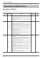
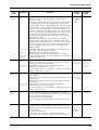
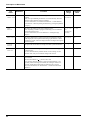
Description of Menu Items ................. 62
3 Setting the Printing Mode and Printing Direction ... 33
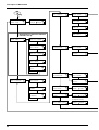
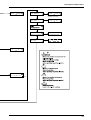
Description of Menus .............................................. 62
Display Menus Flowchart ....................................... 65
Downloading Printing Data ................ 34
What to Do If... ..................................... 68
Remove the Material ........................... 36
Remove the Material From the Machine ................ 36
Cut the Material From the Roll ............................... 36
Error Messages ................................... 72
Specifications ...................................... 73
When Operations Are Finished .......... 38
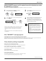
SOLJET™ and SOL INK™ are trademarks of Roland DG Corporation.
COLORCHOICE® is a registered in the U.S. Patent Office.
Windows® is a registered trademark or trademark of Microsoft® Corporation in the United States and/or other countries.
IBM is a registered trademark of International Business Machines Corporation.
Macintosh is a registered trademark or trademark of Apple Computer, Inc. in the USA and other countries.
Other company names and product names are trademarks or registered trademarks of their respective holders.
Copyright © 2002 Roland DG Corporation
http://www.rolanddg.com/
1
To Ensure Safe Use
About
and
Notices
Used for instructions intended to alert the user to the risk of death or severe
injury should the unit be used improperly.
Used for instructions intended to alert the user to the risk of injury or material
damage should the unit be used improperly.
* Material damage refers to damage or other adverse effects caused with
respect to the home and all its furnishings, as well to domestic animals or
pets.
About the Symbols
The
symbol alerts the user to important instructions or warnings. The specific meaning of
the symbol is determined by the design contained within the triangle. The symbol at left means
"danger of electrocution."
The
symbol alerts the user to items that must never be carried out (are forbidden). The
specific thing that must not be done is indicated by the design contained within the circle. The
symbol at left means the unit must never be disassembled.
The
symbol alerts the user to things that must be carried out. The specific thing that must
be done is indicated by the design contained within the circle. The symbol at left means the
power-cord plug must be unplugged from the outlet.
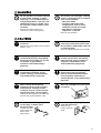
Do not disassemble, repair, or
modify.
Use only with a power supply of the
same rating as indicated on the unit.
Doing so may lead to fire or abnormal
operation resulting in injury.
Use with any other power supply may lead
to fire or electrocution.
Ground the unit with the ground
wire.
Do not use while in an abnormal
state (i.e., emitting smoke, burning
odor, unusual noise, or the like).
Failure to do so may result in risk of
electrical shock in the even of a mechanical
problem.
Use only with the power cord
included with this product.
Use with other than the included power cord
may lead to fire or electrocution.
2
Doing so may result in fire or electrical
shock.
Immediately switch off first the sub power,
then the main power, unplug the power cord
from the electrical outlet, and contact your
authorized Roland DG Corp. dealer or
service center.
Do not operate in a location exposed
to open flame, sparking, or static
electricity, or in a location exposed
to high temperatures, such as in the
immediate vicinity of a heater. Also,
do not place undried media in such
locations.
Doing so may result in fire due to
combustion of ink or cleaning liquid.
Do not store ink cartridges, cleaning
liquid, or discharged ink in locations
such as the following.
• Near open flame
• Locations exposed to high
temperatures, such as in the
immediate vicinity of a heater
• Near bleach, chemicals,
explosives, or the like
Doing so may cause fire.
Ensure adequate ventilation for the
work area.
Failure to do so may result in odor, physical
distress, or fire.
Do not allow ink or cleaning liquid to
come into contact with eyes or skin.
Do not drink or deliberately smell ink
or cleaning liquid.
Doing so may be hazardous to your health.
If ink or cleaning liquid comes in
contact with the eyes, immediately
flush with running water for at least
15 minutes. If eye irritation
continues, seek treatment by a
physician.
If ink or cleaning liquid comes in
contact with the skin, immediately
wash well with soap and water. If
irritation or inflammation occur,
seek treatment by a physician.
If ink or cleaning liquid is
accidentally swallowed, do not
induce vomiting, and immediately
seek treatment by a physician.
If the odor of the ink or cleaning
liquid causes physical distress,
move to a well-ventilated location
and rest quietly. If dizziness or
nausea persists, seek treatment by a
physician.
When storing discharged ink
temporarily, place in the included
drain bottle or a durable sealed
container such as a metal can and
polyethylene tank, and cap tightly.
Store ink cartridges out of the reach
of children.
Leakage of discharged ink or its vapor may
result in odor, physical distress, or fire.
Do not use with a damaged power
cord or plug, or with a loose
electrical outlet.
Use with any other
power supply may
lead to fire or
electrocution.
Do not attempt to unplug the power
cord with wet hands.
Doing so may
result in electrical
shock.
3
Do not injure or modify the electrical
power cord, nor subject it to
excessive bends, twists, pulls,
binding, or pinching, nor place any
object of weight on it.
When unplugging the electrical
power cord from the power outlet,
grasp the plug, not the cord.
Unplugging by pulling the cord may damage
it, leading to fire or electrocution.
Doing so may
damage the
electrical power
cord, leading to
electrocution or
fire.
Do not allow liquids, metal objects
or flammables inside the machine.
Such materials
can cause fire.
Install in a level and stable location.
Otherwise the unit may tip over and cause
injury.
Use care to avoid pinching the
fingers when placing the unit on the
stand.
Doing so may
result in injury.
Roll material must be placed at a
predetermined shaft position.
Failure to do so may
result in falling of the
roll, leading to injury.
4
Unpacking, installation, and moving
must be carried out by four or more
persons.
Otherwise the machine or the stand may
fall, resulting in injury.
Use the joining screws to secure the
unit to the stand.
Failure to do so
may result in
falling of the unit,
leading to injury.
Release the caster locks for the
stand before attempting to move.
Otherwise the unit may tip over and cause
injury.
Do not place hands within the space
to the front of the unit while in
operation.
Doing so may result in injury.
Do not touch the tip of the
separating knife with your fingers.
Doing so may result in injury.
Make sure the power to the unit is
off before attempting to replace the
separating knife.
Doing so may result in injury.
5
About the Labels Affixed to the Unit
These labels are affixed to the body of this product.
The following figure describes the location and content of these messages.
Ink cartridge
Ink and discharged ink are flammable.
Keep away from open flame.
Ink and discharged ink are toxic. Avoid
contact with the body. Use only in a
well-ventilated area.
Do not dismantle the cartridge.
Keep out of reach of children.
Do not store the cartridge in high or freezing temperatures.
Use only models that support SOL INK. Do not insert this cartridge into a model that does
not support SOL INK.
When closing the front cover,
be careful not to pinch your
fingers.
6
Do not place hands
within the space to
the front of the unit
while in operation.
Ink and discharged ink are
flammable. Keep away
from open flame.
Ink and discharged ink are
toxic. Avoid contact with the
body. Use only in a wellventilated area.
Model name
Rating label
Use a rated power
supply.
In addition to the
NOTICE
and
symbols, the symbols shown below are also used.
: Indicates information to prevent machine breakdown or malfunction and ensure correct use.
: Indicates a handy tip or advice regarding use.
7
Pour utiliser en toute sécurité
Avis sur les avertissements
Utilisé pour avertir l'utilisateur d'un risque de décès ou de blessure grave en
cas de mauvaise utilisation de l'appareil.
Utilisé pour avertir l'utilisateur d'un risque de blessure ou de dommage
matériel en cas de mauvaise utilisation de l'appareil.
* Par dommage matériel, il est entendu dommage ou tout autre effet
indésirable sur la maison, tous les meubles et même les animaux
domestiques.
À propos des symboles
Le symbole
attire l'attention de l'utilisateur sur les instructions importantes ou les
avertissements. Le sens précis du symbole est déterminé par le dessin à l'intérieur du triangle.
Le symbole à gauche signifie "danger d'électrocution".
Le symbole
avertit l'utilisateur de ce qu'il ne doit pas faire, ce qui est interdit. La chose
spécifique à ne pas faire est indiquée par le dessin à l'intérieur du cercle. Le symbole à
gauche signifie que l'appareil ne doit jamais être démonté.
Le symbole
prévient l'utilisateur sur ce qu'il doit faire. La chose spécifique à faire est
indiquée par le dessin à l'intérieur du cercle. Le symbole à gauche signifie que le fil électrique
doit être débranché de la prise.
Ne pas démonter, réparer ou
modifier.
Le non-respect de cette consigne pourrait
causer un incendie ou provoquer des
opérations anormales entraînant des
blessures.
Mettre l'appareil à la masse avec une
prise de terre.
Le non-respect de cette consigne pourrait
entraîner des décharges électriques en
cas de problème mécanique.
N'utilisez que le cordon
d'alimentation fourni avec ce
produit.
L’utilisation avec un autre cordon
d’alimentation que celui fourni pourrait
entrainer un risque d’incendie ou
d’électrocution.
8
Utiliser seulement avec une
alimentation de mêmes
caractéristiques électriques que
celles indiquées sur l'appareil.
Une négligence à ce niveau pourrait
provoquer un incendie ou une
électrocution.
Ne pas utiliser si l'appareil est dans
un état anormal (c'est-à-dire s'il y a
émission de fumée, odeur de brûlé,
bruit inhabituel etc.).
Le non-respect de cette consigne pourrait
provoquer un incendie ou des décharges
électriques.
Couper immédiatement l'alimentation
secondaire et ensuite l'alimentation
principale. Débranchez le fil électrique et
contacter votre revendeur ou votre centre
de service de la société Roland DG
autorisé.
Ne pas utiliser près d'une flamme nue,
dans un endroit où se produisent des
étincelles ou de l'électricité statique,
ni dans un endroit où les températures
sont élevées, par exemple à proximité
d'un appareil de chauffage.
De plus, il ne faut pas placer le support
humide dans de tels endroits car la
combustion de l'encre ou du liquide nettoyant
peut créer un risque d'incendie.
Ne pas entreposer les cartouches
d'encre, le liquide nettoyant ou l'encre
usée dans les endroits suivants :
• près d'une flamme nue,
• dans des endroits où les
températures sont élevées, par
exemple à proximité d'un appareil
de chauffage,
• près de javellisants, de produits
chimiques, d'explosifs ou autres
produits semblables.
Cela crée un risque d'incendie.
S'assurer que le lieu de travail est bien
aéré.
Sinon, des odeurs fortes peuvent se dégager
et il y a risque de malaises physiques ou
d'incendie.
Ne pas mettre le liquide nettoyant en
contact avec les yeux ou la peau. Ne
pas boire ou ni respirer délibérément
l'encre ou le liquide nettoyant.
Cela est dangereux pour la santé.
Si de l'encre ou le liquide nettoyant
viennent en contact avec les yeux,
rincer immédiatement à l'eau courante
pendant au moins 15 minutes. Si les
yeux sont toujours irrités, consulter
un médecin.
Si de l'encre ou du liquide nettoyant
entrent en contact avec la peau,
immédiatement laver à fond avec de
l'eau et du savon. Si la peau devient
irritée ou inflammée, consulter un
médecin.
Si de l'encre ou du liquide nettoyant
sont avalés accidentellement, ne pas
provoquer le vomissement, et
consulter un médecin immédiatement.
Si l'odeur de l'encre ou du liquide
nettoyant cause un malaise physique,
amener immédiatement la personne
dans un endroit bien aéré et la laisser
se reposer. Si l'étourdissement ou les
nausées persistent, consulter un
médecin.
Pour entreposer temporairement
l'encre usée, la placer dans un solide
contenant scellé, par exemple un
contenant en métal et un réservoir en
polyéthylène, et fermer
hermétiquement.
Ranger les cartouches d'encre hors
de portée des enfants.
Les fuites d'encre usée ou la vapeur qui s'en
échappe peuvent causer des odeurs fortes,
des malaises physique ou un incendie.
Ne pas utiliser avec une fiche ou un
fil électrique endommagé ou avec
une prise mal fixée.
Une négligence à
ce niveau pourrait
provoquer un
incendie ou une
électrocution.
Ne pas essayer de débrancher le fil
avec des mains mouillées.
Une négligence à
ce niveau pourrait
provoquer des
décharges
électriques.
9
Ne pas endommager ou modifier le
fil électrique. Ne pas le plier, le
tordre, l'étirer, l'attacher ou le serrer
de façon excessive. Ne pas mettre
d'objet ou de poids dessus.
Saisir la fiche et non le fil électrique
lorsque vous débranchez.
Débrancher en tirant sur le fil pourrait
l'endommager et risquer de provoquer un
incendie ou une électrocution.
Une négligence à
ce niveau pourrait
endommager le fil
électrique ce qui
risquerait de
provoquer une
électrocution ou un
incendie.
Ne pas introduire de liquide, d'objet
métallique ou inflammable dans
l'appareil.
Ce genre de
matériel peut
provoquer un
incendie.
Le non-respect de cette consigne pourrait
causer des défauts dans l’appareil
entraînant des blessures.
Installer dans un endroit stable et de
niveau.
Utiliser les vis fournies pour bien
fixer l'appareil sur le support.
Sinon l'appareil pourrait se renverser et
provoquer des blessures.
Le non-respect de
cette consigne
pourrait causer des
défauts dans
l'appareil entraînant
des blessures.
Manipuler avec précaution pour
éviter de se coincer les doigts lors
de l'installation de l'appareil sur le
support.
Débloquer le mécanisme d'arrêt des
roulettes du support avant de le
déplacer.
Une négligence à
ce niveau pourrait
provoquer des
blessures.
Le rouleau doit être placé quand la
barre est en position adéquate.
Une négligence à ce
niveau pourrait
provoquer la chute du
rouleau et causer des
blessures.
10
Le déballage, l’installation et le
déplacement de l’appareil doivent
être effectués par quatre personnes
ou plus.
Sinon l'appareil pourrait se renverser et
provoquer des blessures.
Ne pas mettre les mains dans
l'espace du devant quand l'appareil
est en marche.
Une négligence à ce niveau pourrait
provoquer des blessures.
Ne pas toucher le bout de la lame
séparatrice avec les doigts.
Une négligence à ce niveau pourrait
provoquer des blessures.
S'assurer que l'appareil est hors
tension avant d'essayer de
remplacer la lame séparatrice.
Une négligence à ce niveau pourrait
provoquer des blessures.
11
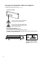
À propos des étiquettes collées sur l'appareil
Ces étiquettes sont collées à l'extérieur de l'appareil.
Les dessins suivants indiquent l'endroit et le contenu des messages.
la cartouche d'encre
L'encre et l'encre usée sont inflammables.
Les garder loin de toute flamme nue.
L'encre et l'encre usée sont toxiques. Éviter
tout contact avec le corps. Utiliser uniquement
dans un endroit bien aéré.
Ne pas démonter la cartouche.
Conserver hors de la portée des enfants.
Ne pas emmagasiner á das températures hautes ou basses.
À n'utiliser que sur les modèles acceptant SOL INK. Ne pas insérer cette cartouche dans
les modèles n'acceptant pas SOL INK.
Manipuler avec précaution pour
éviter de se coincer les doigts
lors de la fermeture du couvercle
de devant.
12
Ouvrir la plaque avant pendant l’impression
provoque un arrêt d’urgence.
Appuyer sur [PAUSE] si, pour toute autre
raison qu’une urgence, vous désirez
suspendre momentanément l’impression.
Ne pas mettre les
mains dans l'espace
devant l'élément
quand celui-ci est en
marche.
L'encre et l'encre usée
sont inflammables. Les
garder loin de toute
flamme nue.
L'encre et l'encre usée
sont toxiques. Éviter tout
contact avec le corps.
Utiliser uniquement dans
un endroit bien aéré.
Nom du modèle
Étiquette
des
caractéristiques
électriques
Utiliser l'alimentation
appropriée
Utiliser uniquement l'encre SOL INK. Ne pas
utiliser d'autres types de cartouches d'encre.
13
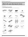
What to Do upon Opening the Carton
What to Do upon Opening the Carton
In this manual, sections that explain commons points for the SJ-600/500 use only illustrations of the SJ-600. Some details of the SJ-500
differ from the figure.
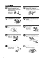
1 Checking Accessories
Check the following to make sure that you received all the items that were shipped along with the unit.
14
Power cord: 1
Stays : 2
(For place the media guide)
Bolts (Large) : 14
(For assembling stand)
Bolts (Small) : 4
(For assembling stand)
Washers : 6
(For assembling stand)
Hexagonal wrench (M6) : 1
(For assembling stand)
Pipe : 1
(For assembling stand)
Stand leg : 1
Media guide : 1
Caster : 2
Media flanges : 2
Flange retaining pins : 2
Drain bottle: 2
Media clamps : 2
Roland ColorChoice® : 1
User’s manual: 1
Replacement blade for
separating knife: 1
Cleaning kit: 1
What to Do upon Opening the Carton
2 Assembling the Stand and the Machine
Unpacking, installation, and moving
must be carried out by four or more
persons.
Use care to avoid pinching the
fingers when placing the unit on the
stand.
Otherwise the machine or the stand may fall,
resulting in injury.
Doing so may
result in injury.
Use the joining screws to secure the
unit to the stand.
Failure to do so may
result in falling of the
unit, leading to
injury.
NOTICE
When lifting the machine, do not grasp the
areas shown in the figure.
Doing so may damage the equipment.
Left-hand side of the
back of the unit
Right-hand side of the
back of the unit
First assemble the stand, then mount the machine on top of the stand.
The external dimensions of the assembled machine and stand are as follows.
SJ-600:
SJ-500:
1
2500 mm [W] x 758 mm [D] x 1241 mm [H] (98-7/16 in. [W] x 29-7/8 in. [D] x 48-7/8 in. [H])
2246 mm [W] x 758 mm [D] x 1241 mm [H] (88-7/16 in. [W] x 29-7/8 in. [D] x 48-7/8 in. [H])
Short
Invert the stand legs as shown in the
figure. While supporting the stand legs
with your hand, attach the left- and righthand casters.
Tighten the bolts securely. Loose bolts
may cause the stand to wobble.
Hexagonal wrench
Long
Bolts (Large)
Pipe
4 pcs.
4 pcs.
Continued on the next page.
15
What to Do upon Opening the Carton
2
Set the stand upright so that the casters are at the bottom, and place the machine on the stand.
The front and rear of the stand are as shown in the figure.
* Take care to prevent
from catching on the
bottom plug at the
bottom surface on
the right side of the
machine.
* Line up the frame at the
back of the machine with
the fixtures on the stand.
Front
3
Use the included large bolts to secure the machine to the stand.
Three places each
on the left and right
Washer
Bolt (Large)
4
Fit the stays onto the back of the machine at the locations shown in the figure.
Left-hand side of the
back of the unit
Stay
16
Right-hand side of the
back of the unit
Stay
What to Do upon Opening the Carton
5
Place the media guide on the stays and secure it in place using the included small bolts.
Orientation of the media guide
Rear
Media guide
Front
Media
guide
Bolts (Small)
Long
Short
* If the short side is oriented
toward the back of the machine,
roll material may fall.
6
Pass the media flanges onto the retainers and
secure in place with the flange retaining pins.
Orient the media flange so that it's lined up with
the core diameter of the loaded roll material.
2 in.
3 in.
Media flanges
Retainer
1)
Left-hand side of
the back of the unit
1)
Line up the ridges
and grooves.
30%
Right-hand side of
the back of the unit
Flange retaining pins
2)
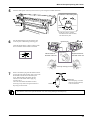
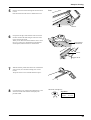
7
Remove the bottom plug from the bottom surface
on the right side of the machine, then screw in the
drain bottle in the direction indicated by the
arrow. When threading the bottle onto the
machine, turn the bottle without applying
excessive force.
Leave the drain bottle attached at all times,
removing it only when moving the machine or
disposing of collected ink.
2)
Bottom plug
Drain bottle
* The bottom plug is needed
when moving the machine,
so do not discard it.
The machine comes with a spare drain bottle. Use it for storing discharged ink temporarily.
17
What to Do upon Opening the Carton
3 Setting Up and Connection
Setting Up
Unpacking, installation, and moving
must be carried out by four or more
persons.
Install in a level and stable location.
Otherwise the unit may tip over and cause
injury.
Otherwise the machine or the stand may
fall, resulting in injury.
NOTICE
Be sure to install the drain bottle before switching on the power.
Use in the following environment.
• Temperature: 15 to 35 ˚C (59 to 95 ˚F), humidity: 35 to 80 % (no condensation)
Also, take care to ensure that the following conditions are not exceeded even when the machine is not in operation. In particular, be careful to make sure not to expose the machine to high temperatures of 40 ˚C (104 ˚F) or
more.
• Temperature: 5 to 40 ˚C (41 to 104 ˚F), humidity: 20 to 80 % (no condensation)
Never install the unit in any of the following situations, as it could result in breakdown or faulty operation:
• Places where the installation surface is unstable or not level.
• Places with excessive electrical noise.
• Places with excessive humidity or dust.
• Places with poor ventilation, because the unit generates considerable heat during operation.
• Places with excessive vibration.
• Places exposed to strong illumination or direct sunlight.
Never step or stand on the stand legs, as doing so may damage them.
Do not place objects on the unit, as doing so may result in breakdown.
The required installation spaces for this model are listed below.
SJ-600: 3500 mm [W] x 2000 mm [D] x 1700 mm [H]
(137-13/16 in. [W] x 78-3/4 in. [D] x 66-15/16 in. [H])
SJ-500: 3300 mm [W] x 2000 mm [D] x 1700 mm [H]
(129-15/16 in. [W] x 78-3/4 in. [D] x 66-15/16 in. [H])
18
What to Do upon Opening the Carton
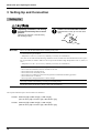
Connection
Use only with a power supply of the
same rating as indicated on the unit.
Ground the unit with the ground
wire.
Use with any other power supply may lead
to fire or electrocution.
Failure to do so may result in risk of
electrical shock in the even of a mechanical
problem
Use only with the power cord
included with this product.
Use with other than the included power cord
may lead to fire or electrocution.
NOTICE
Before connecting the cable, make sure the computer's power and the main power switch of the unit are
switched off.
Securely connect the power cord, computer I/O cable and so on so that they will not be unplugged and cause
failure during operation. Doing so may lead to faulty operation or breakdown.
Arrange the power cord and interface connection cable to prevent tripping when moving around the unit.
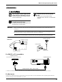
Side View
Power connector
Parallel connector
Power outlet
Power cord
Power connector
For IBM PC or PC compatibles
Parallel connector
Secure the cable in place with the clips.
Parallel connector
Parallel interface cable (Printer cable)
* Cables are available separately. One which you are sure matches the model of computer being used should be selected.
For Macintosh
Connection to a Macintosh requires optional items such as special cable. For more information on the required optional items and
connection settings, contact a Roland DG Corp. dealer.
19
What to Do upon Opening the Carton
4 Installing Ink Cartridges
Do not operate in a location exposed
to open flame, sparking, or static
electricity, or in a location exposed
to high temperatures, such as in the
immediate vicinity of a heater. Also,
do not place undried media in such
locations.
Doing so may result in fire due to
combustion of ink or cleaning liquid.
Do not store ink cartridges, cleaning
liquid, or discharged ink in locations
such as the following.
• Near open flame
• Locations exposed to high
temperatures, such as in the
immediate vicinity of a heater
• Near bleach, chemicals,
explosives, or the like
Doing so may cause fire.
Ensure adequate ventilation for the
work area.
Failure to do so may result in odor, physical
distress, or fire.
Do not allow ink or cleaning liquid to
come into contact with eyes or skin.
Do not drink or deliberately smell ink
or cleaning liquid.
Doing so may be hazardous to your health.
Store ink cartridges out of the reach
of children.
NOTICE
Do not use anything other SOL INK cartridges. Do not attempt to refill and reuse an empty ink cartridge.
Do not remove any ink cartridges except when shipping the machine.
If ink runs out, replace immediately with the same type and the same color ink cartridge (see "Maintenance Replacing the Ink Cartridges"). If an ink cartridge is removed, replace it immediately with a new one.
Do not attempt to disassemble an ink cartridge.
Store ink cartridges unopened at a temperature of -20 to 40 ˚C (-4 to 104 ˚F) in a well-ventilated location.
If an ink cartridge is dropped, the shock due to the fall may damage the ink cartridge and make it unusable.
When installing and removing an ink cartridge, do not rush. Detach the cartridge gently. Sudden movement
when detaching may cause ink to be spilled.
Once an ink cartridge has been installed, do not remove it until the ink has been used up. Frequent insertion and
removal may allow air to enter the ink tube and result in a drop in printing quality due to dot drop-out or the like.
20
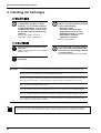
What to Do upon Opening the Carton
Installing ink cartridges for the first time after purchase requires three SOL INK cleaning cartridges. This is also the case when you are
draining ink in preparation for transport, then reinstalling the ink cartridges.
NOTICE
Use only SOL INK. Do not insert any other type of ink cartridge.
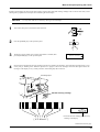
1
Turn on the main power switch at the back of the unit.
2
Press the [POWER] key on the operation panel.
3
The display appears. Make sure an empty drain bottle is installed, then
press the [ENTER] key on the operation panel.
4
Insert cleaning cartridges into the ink-cartridge ports shown by flashing on the display. Insert the three cartridges firmly, as far
as they will go. Washing starts. While the operation is in progress, remove the cartridges and insert them again. Follow the
messages on the display to carry out the procedure. Ink washing may take some time.
INSTALL
DRAIN BOTTLE
Ink cartridge ports
SOL INK cleaning cartridge
SET CL-LIQUID
[KCMcmY]
[ KCMcmY ]
* Insert into the ink cartridge ports shown by
flashing on the display.
Continued on the next page.
21
What to Do upon Opening the Carton
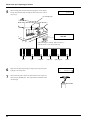
5
When washing ends, the following message appears on the display.
Firmly insert the SOL INK cartridges for each of the colors as far as
they will go.
SET CARTRIDGE
[KCMcmY]
Ink cartridge ports
SOL INK
When inserting the cartridge, make sure that it is
inserted into the correct slot for that color.
Black
Cyan
Magenta
Light cyan
6
Make sure the following message is displayed, then press the [ENTER] key. Ink filling starts.
7
When ink filling ends, replace the drain bottle with an empty one,
then press the [ENTER] key. This completes the installation of the
ink cartridges.
Light magenta
Yellow
SELECT INK TYPE
SOL
CMYKLcLm
Drain bottle
22
Part Names
Part Names
Front View
NOTICE
If you will leave the printing head being uncapped for a long time (for example, open the front cover while
printing is made on the middle of platen), printing heads may get clogging and, in some case it results unrecoverable damage to the printing head.
When the carriage is stopped on the platen, press the [POWER] key to reset the power. The carriage moves and
the printing head is capped.
Do not touch the rail or place the hands
inside the right-hand cover.
Touching the area shown may cause the
fingers to be soiled by grease or ink, and
may result in diminished image quality.
Rail
Do not put hands inside
Front cover
If the cover is opened while the printing, it will
execute an emergency stop.
Sheet Loading Lever
Operation panel
Drain bottle
23
Part Names
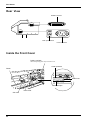
Rear View
Parallel connector
Main power switch
Power connector
Inside the Front Cover
Printing carriage
When not printing, this stays inside the cover.
Cutter protector
Platen
Guide lines
Reflective tape
Pinch roller
Grit roller
24
Part Names
Operation Panel
For more information about the keys, take a look at "Description of Keys".
Display
This show the various
setting menus, and
messages.
[PRINT QUALITY] key
[SETUP] key/LED
[CLEANING] key
[PAUSE] key/LED
[BASE POINT] key/LED
[SHEET CUT] key
([
[MENU] key
BUSY LED
Arrow keys
] [ ] [
] [
])
[ENTER] key
[POWER] key/LED
This flashes while data
is being received from
the host computer.
25
Five Modes
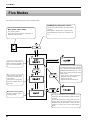
Five Modes
This machine has the following five modes (operating states).
[POWER] key (Sub power switch)
Main power switch (Side)
It is generally left on.
Please do not turn it off unless transporting or
maintaining the main unit.
Use this switch to turn power on and off in daily
operation.
When power is turned on the system will enter
the NOT READY state (power on but sheet not
set).
This mode is in effect immediately after the [POWER]
key is pressed to switch on.
This is the state where material has been loaded and its
size detected.
The system can accept data
from the computer when in
this mode.
The system is receiving data
from the computer and performing printing.
26
The SLEEP mode is enabled when the
system has been inactive for a specified
time. (When in the SLEEP mode, the
POWER LED flashes once per 2 seconds.) Any action of following cancels
SLEEP mode.
• Touch any key on the control panel.
• Send data from the computer.
• Open the front cover.
• Operate the sheet loading lever.
Pressing the PAUSE key causes operation to stop
temporarily. Press the PAUSE key again to resume
operation.
Pressing the SETUP key while paused causes remaining data to be cleared and returns to the NOT
READY mode. If the material is removed while
paused, the system goes into the NOT READY
mode.
Setup for Printing
Setup for Printing
NOTICE
Load roll material at the proper
position.
When closing the front cover, be
careful not to pinch your fingers.
Otherwise the roll may
fall, resulting in injury.
Doing so may result in injury.
Before loading roll material, be sure to install the media guide.
When the machine will remain unused for an extended period, remove roll material from the machine and
store it.
If roll material is left mounted on the machine for an extended period, these entire roll may warp, resulting in
poor printed image quality or motor errors.
- When transparent material is loaded, it is necessary to set [SHEET TYPE] to [CLEAR]. For more information, see
"What to Do If..." ( [SHEET SET ERROR SET AGAIN] appears and the material cannot be detected even when the
[SETUP] key is pressed).
- When loading thicker material or material that is prone to warping, it may be necessary to adjust the head height.
For more information, see "User's Reference -- Adjusting the Height of the Printing Head."
- When changing to a different type of material, it may be necessary to perform feed correction or bidirectional
correction. For more information, see "User's Reference -- Making Corrections for Printing."
- When the left or right edges of the material are warped, use the media clamps. Performing printing without using the
media clamps may result in scraping of the heads or jammed material. Scraping of the heads and jammed material
may damage or soil the printing heads, resulting in poorer printing accuracy. Do not use material that is so strongly
warped that the media clamps are lifted.
Acceptable material widths
-SJ-600
-SJ-500
210 to 1625 mm (8-5/16 to 64 in.)
210 to 1371 mm (8-5/16 to 54 in.)
27
Setup for Printing
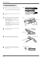
1 Loading the Material
Loading Roll Material
1
Open the front cover.
2
Line up with the core diameter of the loaded roll material and refit the left- and right-hand media flanges.
(1)
(2)
Media flange
Media flange
50.8 mm
(2 in.)
76.2 mm
(3 in.)
Flange retaining pin
(4)
(3)
Line up the ridges and grooves.
3
Fit the hole on the left side of the roll material all the way onto the left-hand media flange.
4
Fit the right-hand media flange all the way into the hole on the right-hand side of the roll material, and tighten the retainer screw
to secure in place.
Roll material
Left-hand media flange
28
Right-hand media flange
Setup for Printing
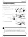
5
Pass the end of the material through the unit from back
to front.
Pull out material until the sensor is hidden from view.
Front
Material
6
Sensor
Grasp the front edge of the material at the front of the
machine and turn the media flanges at the back of the
unit to roll back the media.
When you roll back the material until the sensor comes
into view, a tight seal is formed between the material
and the platen, and the material is stretched taut.
Entire material
stretched taut
Sensor
7
With the material pulled out from the roll stretched taut
with no slack, move the sheet loading lever toward
LOAD.
The pinch rollers lower to hold the material in place.
8
Close the front cover, and press the [SETUP] key. This
detects the width of the material and displays the
printable width.
The SETUP LED lights up
Top menu
W 1234 mm
NORMAL
BI-DIR
29
Setup for Printing
Loading Sheet Material
1
Remove the left-hand media flange at the back of the
unit.
Move the right-hand media flange at the back of the unit
to a position where it does not touch the loaded material.
2
Pass the material between the pinch rollers and the grit
rollers.
3
Line up the right-hand side of the material with the
guide line, and line up the front edge of the material
with the reflective tape.
If the front edge of the material has been cut at an
angle, pull out the material so that all of the material
covers the reflective tape.
* Be sure to line up the right-hand edge of the material
with the guide line.
If the material is not positioned correctly when you
press the [SETUP] key, the message "SET AGAIN"
appears on the display.
4
Front
Sheet material
Front
Guide line
Reflective tape
Material
Drape the pulled-out portion at the back between the
unit and the media guide.
Media guide
5
Move the sheet loading lever toward "LOAD".
The pinch rollers lower to hold the material in place.
6
Close the front cover, and press the [SETUP] key.
This detects the width of the material and displays the
printable width.
30
Sheet loading lever
The SETUP LED lights up
Top menu
W 300 mm
NORMAL
BI-DIR
Setup for Printing
Loading Material Prone to Warping
When you are loading material whose left and right edges are prone to warping, use the media clamps. At such times, perform printing
with the printing heads positioned at "3" (high). For more information about the height of the printing heads, refer to "User's Reference - Adjusting the Height of the Printing Head."
Installing the Media Clamps
Holes
1
Line up the holes in the media clamps with the left and
right edges of the material. At this time, loosen the
screws on the media clamps, but do not loosen them so
much that they come off completely.
Material
Media clamps
Screws
2
Media clamp
Insert the media clamps into the grooves as shown in the
figure.
Material
Groove
Insert this portion.
Insert the media clamp in the
same way at the left edge of
the material as well.
3
Tighten the screws to secure the media clamps in
place.
Screw
- When you are using the media clamps, attempting to cut off the material causes the material to come loose from the
media clamps. If this happens, reinstall the media clamps.
- When you are not using the media clamps, remove them from this machine.
- As printing proceeds, the material may move to the left right and touch or come loose from the media clamps. After
about 1 m (39-3/8 in.) of material has been fed, check the positioning of the media clamps. If the material looks like
it may come loose from the media clamps, adjust the positioning of the media clamps.
- The media clamps are designed to press down on a space 10 mm (7/16 in.) inward from either edge of the material.
Do not perform printing within these areas.
31
Setup for Printing
Setup for Printing
2 Test Printing
Printing quality is greatly affected by the state of the printing heads.
Before starting to print, you can carry out a printing test to check the state of the printing heads.
If the printing heads are in a poor state and problems such as dot drop-out occur, printing quality drops.
If the test results show a problem, carry out head cleaning to restore the head to its normal state.
1
Load a material, then close the front cover.
2
Press the [CLEANING] key to execute [TEST PRINT].
HEAD CLEANING
START
Press the [ENTER] key,
head cleaning starts.
Press the [ ] key to make
[TEST PRINT] appear on
the display.
HEAD CLEANING
TEST PRINT
Press the [ENTER] key to
print a test pattern.
If there are any missing dots or other evidence
of a drop in printing quality, clean the head
(see "Maintenance -- Cleaning the Printing
Heads").
32
Setup for Printing
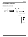
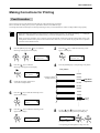
3 Setting the Printing Mode and Printing Direction
Before start to print, set the printing mode and printing direction.
On the control panel, press the [PRINT QUALITY] key and specify the printing mode and direction of printing.
• Printing quality and output time vary according to the printing mode. Choose a mode that matches the task. Note
that when the printing mode can be set on the computer, the computer’s setting takes priority.
• The printing time for the same original data becomes increasingly longer in this sequence: DRAFT, FAST, NORMAL, FINE2/FINE, SUPER, and PHOTO. Also, with this procedure the size of the output file generally grows
larger, and the processing time for creating the output file also becomes longer.
It's also necessary to ensure enough memory on the computer.
Printing Mode
Printing Direction
PHOTO:
This is suitable for printing photographs.
SUPER:
This is suitable for output with high image
quality, such as posters.
UNI-DIRECTION:
Unidirectional printing.
Printing is performed as the carriage moves from right to left.
Printing quality is better than with [BI-DIRECTION].
FINE:
This is suitable for output with comparatively
high detail, such as posters.
FINE2:
(Factory
default)
This is suitable for outputting posters and the
like on various materials.
NORMAL:
This is suitable for printing large-size items
with comparatively high quality in a short
time.
FAST:
This is suitable for printing large-size items in
a short time.
DRAFT:
This can produce output in the shortest time. It
is suitable for checking layout and the like.
1
Press the [PRINT QUALITY] key.
BI-DIRECTION (factory default):
Bidirectional printing.
Printing is performed as the carriage moves from right to left,
and also as it returns from left to right.
Printing speed is faster than with [UNI-DIRECTION].
2
Use the [
mode.
] and [
] keys to choose the printing
PRINT MODE
FINE
3
Press the [
] key to make the setting for the printing direction.
Use the [ ] and [ ] keys to display the printing direction, then
press the [ENTER] key.
PRINT QUALITY
BI-DIRECTION
33
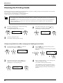
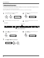
Downloading Printing Data
Downloading Printing Data
NOTICE
Opening the front cover while printing is in progress causes an emergency stop. This means that printing may
not be carried out correctly even if operation is resumed, due to drop-out or misalignment of the image.
To pause printing for any other reason than an emergency stop, press the [PAUSE] key.
Note pressing the [PAUSE] key to pause operation may result in differing image quality before and after the
pause. It is a good idea to avoid pausing operation while printing is in progress whenever possible.
If you will leave the printing head being uncapped for a long time (for example, open the front cover while
printing is made on the middle of platen), printing heads may get clogging and, in some case it results unrecoverable damage to the printing head.
Do not use the [ ] key to return a portion of the material that’s already been printed. The pinch rollers may
pass over the printed surface, smudging the ink.
Also, do not use the [ ] and [ ] keys to feed and return unprinted portions many times. The grit rollers may
make tracks on the material, resulting in poor printing precision.
Printing is started when data is sent.
If the top menu isn't displayed, printing doesn't start even when data is sent from the computer.
Top menu
Conditions for starting printing
The material must be already set up (with the SETUP LED lighted),
and the display must show the top menu.
W1234mm
FINE
L ---mm
BI-DIR
If another menu screen is displayed, press the [SETUP] key to go back to the top menu.
(Pressing the [SETUP] key when another menu screen is displayed does not cancel the set-up for the material.)
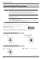
Pausing Printing Operations
Press the [PAUSE] key.
To resume printing
Press the [PAUSE] key.
The PAUSE LED lights up
The PAUSE LED goes out
Stopping Printing Operations
1
Press the [PAUSE] key.
The PAUSE LED lights up
2
Halt transmission of print instructions from the
computer.
Continued on the next page.
34
Downloading Printing Data
3
Hold down the [SETUP] key for one second or longer.
Any remaining data is cleared.
The SETUP LED goes out
* Clearing the data
may take some
time.
If the "INK EMPTY" Message Appears While Printing
If it becomes necessary to replace the ink cartridge while printing is in
progress, the buzzer sounds and the following message is displayed.
Please replace the ink cartridge.
If this message is ignored and printing is continued without replacing the
ink cartridge, image quality may be adversely affected and exhibit
faintness or other problems.
INK EMPTY
[KCMcmY]
This indicates the ink color.
The color for which ink has run out flashes.
K = Black / C = Cyan / M = Magenta /
c = Light Cyan / m = Light Magenta /
Y = Yellow
When [INK CONTROL]'s [EMPTY MODE] is set to [LATER]
1
Press the [PAUSE] key to pause printing.
2
Pull out the cartridge for the ink color that has run out,
and replace with a new cartridge (see "Maintenance -Replacing the Ink Cartridges").
3
Press the [PAUSE] key to resume printing.
The PAUSE LED lights up
The PAUSE LED goes out
When [INK CONTROL]'s [EMPTY MODE] is set to [PROMPT]
The unit pauses automatically.
About the [EMPTY MODE]
When replacement of the ink cartridge becomes necessary while printing is in progress, this setting determines whether printing
continues or pauses.
This setting is used when the ink cartridge cannot be changed immediately during printing, such as during unattended operation at
night. [LATER] causes printing to continue without pause even if ink refilling becomes necessary. Printing continues with the small
amount of ink remaining, so the printed image may become faint as the ink runs out. In general, it should possible to perform about 1
m2 (10 ft2) of printing once this message appears, although the actual varies widely according to the amount of ink needed for the
particular image. Printing is continued only for the data currently being printed. Operation stops after one image is output.
[PROMPT] causes operation to pause immediately when the ink cartridge needs to be changed. Printing is resumed by replacing the
cartridge and pressing the [PAUSE] key. Please note, however, that the colors of an image in progress may no longer be perfectly
matched if the unit is allowed to remain paused for two or three hours before resuming printing.
35
Remove the Material
Remove the Material
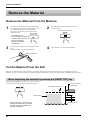
Remove the Material From the Machine
1
If you wish to cut off the piece of the rolled material
containing the printed area, press the [SHEET CUT]
key. Hold down for about 1 second or longer.
The piece is cut off at the present location of the
printing-start line.
2
Press the [SETUP] key. Hold down for about 1
second or longer.
The SETUP LED goes out
* This operation isn’t
necessary when sending a
material-cutting command
from the computer to
separate the material
automatically.
3
Move the sheet loading lever toward the back of the
unit.
The pinch rollers rise to release the material.
4
Open the front cover to remove the material.
Sheet loading lever
Cut the Material From the Roll
Either of two methods can be used to separate a portion that's already been cut or printed from the roll. One method is to press the
[SHEET CUT] key. The other method is to perform separation automatically by sending a material-cutting command from the computer.
When separating the material by pressing the [SHEET CUT] key
Holding down the [SHEET CUT] key for 1 second or longer
severs the material at the present location of the blade tip.
Present location of
the blade tip
The material is cut off here.
Printed portion
* This operation isn't necessary when
sending a material-cutting command
from the computer to separate the
material automatically.
36
Printing-start line
Remove the Material
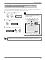
When sending a material-cutting command from the computer
to separate the material automatically
* When the material-cutting command has not been set to "enabled" at the computer, automatic separation of
the material is not performed, even when the following setting is made.
1
Press the [MENU] key and [ ] key to make the
following screen appear on the display.
MENU
AUTO SHEET CUT
2
Press the [
] key to make the following screen
appear on the display.
The material-separating location during
continuous output
Start of the next output
10 mm
(3/8 in.)
AUTO SHEET CUT
DISABLE DISABLE
End of output
3
Use the [ ] key to select [ENABLE], then press the
[ENTER] key.
AUTO SHEET CUT
DISABLE ENABLE
Location where separated
10 mm (3/8 in.)
Margin (value set for [PAGE MARGIN])
Attempting to return or cut off material that has not been allowed to dry sufficiently after printing may soil or damage
the printed surface. Make sure the printed surface has dried sufficiently before you return or cut off the material.
37
When Operations Are Finished
When Operations Are Finished
NOTICE
Even when not in use, keep the machine in an environment where the temperature is 5 to 40 ˚C (41 to 104 ˚F) and
the humidity is 20 to 80 % (no condensation). In particular, be careful to make sure not to expose the machine to
high temperatures of 40 ˚C (104 ˚F) or more.
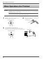
When operations are finished, move the sheet loading lever toward the back of the unit to raise the pinch rollers.
The pinch rollers may be deformed if allowed to remain in the lowered state.
1
If the SETUP LED is lighted, press the [SETUP] key.
Hold down for about 1 second or longer.
2
The SETUP LED goes out
3
Press the [POWER] key to switch off the power.
The carriage moves to the standby position and the head is capped.
If the carriage is already at the standby position, no movement takes place.
Move the sheet loading lever toward the back of the
unit and remove the material.
Sheet loading lever
Standby position
The POWER LED goes out
Carriage
38
Maintenance
Maintenance
Replacing the Ink Cartridges
Do not operate in a location exposed
to open flame, sparking, or static
electricity, or in a location exposed
to high temperatures, such as in the
immediate vicinity of a heater. Also,
do not place undried media in such
locations.
Doing so may result in fire due to
combustion of ink or cleaning liquid.
Do not store ink cartridges, cleaning
liquid, or discharged ink in locations
such as the following.
• Near open flame
• Locations exposed to high
temperatures, such as in the
immediate vicinity of a heater
• Near bleach, chemicals,
explosives, or the like
Doing so may cause fire.
Ensure adequate ventilation for the
work area.
Failure to do so may result in odor, physical
distress, or fire.
Do not allow ink or cleaning liquid to
come into contact with eyes or skin.
Do not drink or deliberately smell ink
or cleaning liquid.
Doing so may be hazardous to your health.
Store ink cartridges out of the reach
of children.
NOTICE
Do not use anything other SOL INK cartridges. Do not attempt to refill and reuse an empty ink cartridge.
Do not remove any ink cartridges except when shipping the machine.
If ink runs out, replace immediately with the same type and the same color ink cartridge. If an ink cartridge is
removed, replace it immediately with a new one.
Do not attempt to disassemble an ink cartridge.
Store ink cartridges unopened at a temperature of -20 to 40 ˚C (-4 to 104 ˚F) in a well-ventilated location.
If an ink cartridge is dropped, the shock due to the fall may damage the ink cartridge and make it unusable.
When installing and removing an ink cartridge, do not rush. Detach the cartridge gently. Sudden movement when
detaching may cause ink to be spilled.
Once an ink cartridge has been installed, do not remove it until the ink has been used up. Frequent insertion and removal
may allow air to enter the ink tube and result in a drop in printing quality due to dot drop-out or the like.
39
Maintenance
NOTICE
1
Use only SOL INK. Do not insert any other type of ink cartridge.
Remove the ink cartridge from the ink-cartridge port.
2
Insert new ink cartridge.
SOL INK
Ink cartridge ports
40
Maintenance
Check How Much Ink Remains
You can use [INK LEFT] on the display menu to check how much ink is left after the ink cartridges have been installed.
Use this information as a guide for replacing the ink cartridges.
If a partially used ink cartridge is removed and reinstalled, or if a partially used ink cartridge is installed, the cartridge is taken to be
unused, and the displaced amount of remaining ink is not true.
1
Press the [MENU] key and [ ] key to make the
following screen appear on the display.
2
Press the [
] key to make the following screen
appear on the display.
The fewer the markers, the less is the amount of ink
left.
MENU
INK LEFT
K
c
C
m
M
Y
K = Black / C = Cyan / M = Magenta /
c = Light Cyan / m = Light Magenta /
Y = Yellow
Remaining ink
Much
No marker
Little
41
Maintenance
Cleaning the Printing Heads
Switching on the sub power automatically performs maintenance operations, including cleaning of the printing head. This means that
there is normally no need to perform cleaning otherwise.
If drop-out occurs with printed images, clean the printing head.
* After cleaning, carry out a printing test. Load material.
The cleaning causes a certain amount of head wear and also consumes a certain amount of ink, so use should be kept
to a minimum.
[POWERFUL] results in faster head wear and also uses up much ink. (Performing cleaning from the [POWERFUL]
menu uses up about 57 cc of ink for six colors. This is because the process discharges all ink in the ink tube and
replaces it with fresh ink.)
1
Press the [CLEANING] key to make the following
screen appear on the display.
Press the [ENTER] key, head cleaning starts.
2
HEAD CLEANING
START
3
When head cleaning ends, press the [ ] key to
display the screen shown in the figure. Press the
[ENTER] key to start the printing test.
HEAD CLEANING
TEST PRINT
Check the printing-test results.
If a problem is found, repeat the cleaning.
If drop-out persists even after carrying out cleaning several times
1
Press the [MENU] key and [ ] key to make the
following screen appear on the display.
2
MENU
HEAD CLEANING
3
When head cleaning ends, press the [ ] key to
display the screen shown in the figure. Press the
[ENTER] key to start the printing test.
HEAD CLEANING
TEST PRINT
42
Press the [
] key to make the following screen
appear on the display.
Press the [ENTER] key, head cleaning starts ([POWERFUL]).
HEAD CLEANING
POWERFUL
4
Refer to “Setup for Printing -- 2 Test Printing” and
check the printing-test results.
If a problem is found, repeat the cleaning.
(The [NORMAL] menu item for [HEAD CLEANING] does the same thing as [HEAD CLEANING] [START] displayed when the [CLEANING] key is
pressed.)
Maintenance
If image drop-out is not corrected even when cleaning has been performed several
times from the [POWERFUL] menu
If image drop-out is not corrected even when cleaning has been performed several times from the [POWERFUL] menu, use the included
cleaning kit. For information on how to use the cleaning kit, refer to the documentation included with the kit.
If cleaning with the cleaning kit does not correct image drop-out, consult your authorized Roland DG Corp. dealer or service center.
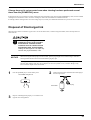
Disposal of Discharged Ink
When the ink is about to exceed the “Upper Limit” line on the drain bottle, or when moving the machine, follow the steps below to
discard the ink.
When storing discharged ink
temporarily, place in the included
drain bottle or a durable sealed
container such as a metal can and
polyethylene tank, and cap tightly.
Leakage of discharged ink or its vapor may
result in odor, physical distress, or fire.
NOTICE
When removing the bottom plug from the machine, pull the plug straight down, without tilting it. Otherwise
discharged fluid that has collected inside the bottom plug may spill.
Discharged ink is flammable and contains toxic ingredients. Do not attempt to incinerate discharged ink or
discard it with ordinary trash. Also, do not dispose of it in sewer systems, rivers, or streams. Doing so may
have an adverse impact on the environment.
1
Press the [POWER] key to switch off the power.
The POWER LED goes out
2
Remove the drain bottle and attach the bottom plug to
the tube tips instead.
Drain bottle
3
Bottom plug
Dispose of discharged ink properly, in accordance with
regional laws and regulations.
43
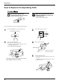
Maintenance
How to Replace the Separating Knife
Do not touch the tip of the
separating knife with your fingers.
Make sure the power to the unit is
off before attempting to replace the
separating knife.
Doing so may result in injury.
Doing so may result in injury.
If the separating knife, replace it with the replacement blade.
1
Press the [POWER] key to switch off the power.
3
Remove the separating knife.
(1) Loosen the screw until it slips out.
(2) Grasp the screw portion, and slowly pull it out in
the direction of the arrow.
* Do not pull back while doing this.
The POWER LED goes out
2
Turn off the main power switch.
4
Replace with a new knife.
Positioning groove
(2)
The knife is secured in
place by the magnet.
(1)
* If the blade remains in the carriage, use commercially available tweezers to remove it.
5
Install the separating knife.
(1) Grasp the screw portion and slowly insert it into
the groove.
* Take care to ensure that the knife does not slip
(2) Tighten the screw.
(1)
(2)
44
Maintenance
When the Product Needs Cleaning
NOTICE
When performing cleaning, turn off the main power switch.
* Before turning off the main power, press the [POWER] key to switch off the sub power.
Never lubricate the mechanisms.
Do not clean with solvents (such as benzine or thinners).
Periodically clean the platen. Attractive printing may become impossible if the platen is soiled.
Do not touch the printing heads or allow the printing heads to come in contact with anything except ink.
Cleaning the body
Use a cloth moistened with water then wrung well, and wipe gently to clean. Wipe the operation panel and display gently with a clean,
dry, and soft cloth.
Cleaning the platen
Use a cloth moistened with water then wrung well, and wipe gently to clean.
Cleaning the grit rollers
Use a commercially available brush to remove dust and other detritus. Brush horizontally while rotating the grit rollers.
Any adhering grime may prevent the material from being held in place securely.
Cleaning the pinch rollers
Use a cloth moistened with water then wrung well, and wipe gently to clean.
Cleaning the reflective tape
If the tape becomes dirty, use a cloth moistened with water then wrung well, and wipe gently to clean.
Cleaning the front cover
Use a cloth moistened with water then wrung well, and wipe gently to clean.
45
Maintenance
When Not in Use for a Prolonged Period...
NOTICE
Even when not in use, keep the machine in an environment where the temperature is 5 to 40 ˚C (41 to 104 ˚F) and
the humidity is 20 to 80 % (no condensation). In particular, be careful to make sure not to expose the machine to
high temperatures of 40 ˚C (104 ˚F) or more.
When not in use, move the sheet loading lever toward the back of the unit to leave the pinch rollers in the up
position state. The pinch rollers may be deformed if allowed to remain in the lowered state.
When the machine is out of use for an extended period, then once a month, switch on the power and perform cleaning. When the machine's
main power switch is left on, a warning beep sounds about once a month to remind you to perform cleaning. We recommend switching off
only the sub power and leaving the main power on even when the machine is out of use for an extended period.
1
When the machine is out of use for about a month, a warning beep
sounds and the following message appears on the display.
2
Press the [POWER] key to switch on the sub power. Cleaning is
performed automatically.
The POWER LED
lights up
3
After cleaning has finished, hold down the [POWER] key for 1 second
or longer to switch off the sub power.
The POWER LED
goes out
46
PRESS THE POWER
KEY TO CLEAN
Maintenance
When Moving the Unit...
NOTICE
When moving the unit, first carry out head washing, then secure the carriage in place.
Head cleaning requires three SOL INK cleaning cartridges, which are optionally available. Be sure to use SOL
INK cleaning cartridges. Use of any other type may result in breakdown.
1
If there is material loaded, hold down the [SETUP]
key for 1 second or longer to cancel setup, then
remove the material (see "Remove the Material").
2
Press the [MENU] key and [ ] key to make the
following screen appear on the display.
MENU
INK CONTROL
3
Press the [
] key to make the following screen
appear on the display.
4
Use the [ ] key to select [HEAD WASH], then press
the [ENTER] key.
INK CONTROL
HEAD WASH
INK CONTROL
EMPTY MODE
5
When the display shown in the figure appears, discard
the discharged ink in the drain bottle.
* Be sure to discard the discharged ink.
Attempting to head washing while discharged ink
remains may cause discharged ink to overflow from
the bottle.
6
Mount the drain bottle and press the [ENTER] key to
display the screen shown in the figure.
REMOVE CARTRIDGE
[KCMcmY]
DISCARD
DRAIN INK
7
When all ink cartridges have been removed, head
washing starts. Follow the messages on the display to
carry out the procedure.
8
When the display shown in the figure appears, head
washing is finished.
Press the [POWER] key to switch off the sub power.
The POWER LED goes out
Messages appearing during head washing
INK CONTROL
HEAD WASH
SET CL-LIQUID
[KCMcmY]
Insert a cleaning cartridge into the ink
cartridge port for the flashing color.
9
REMOVE CL-LIQUID
[KCMcmY]
When the POWER
LED goes out, turn off
the main power switch.
Remove the cleaning cartridge from the ink
cartridge port for the flashing color.
K = Black C = Cyan M = Magenta
m = Light Magenta Y = Yellow
c = Light Cyan
Continued on the next page.
47
Maintenance
10
Detach the power cord and the cable connecting the
unit to the computer.
11
Remove the drain bottle.
Drain bottle
12
48
Referring to "Unpacking and Repacking" on the
packing carton, secure the carriage in place and pack
the unit in the carton.
Bottom plug
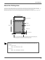
User's Reference
User's Reference
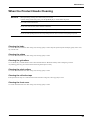
Printing at the Desired Location
This sets the location where printing starts.
Normally the origin point is set at the lower-right point of the printing area.
When [SHEET TYPE] is set to [OPAQUE], the width of
the printing area is set automatically (see "User's Reference -- About the Printing Area").
To determine the desired printing area, follow the steps in
"Setting the printing area in the left-right direction (the
direction of carriage movement)" to set the width of the
printing area. When [SHEET TYPE] is set to [CLEAR],
the printing area is not set automatically, so set the
printing area in the same way. If this setting is not made,
the printing area uses the maximum value for the machine.
Canceling setup cancels the printing area.
Original printing
area
New printing
area
Left-hand edge of the printing area
Right-hand edge of the printing area
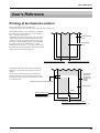
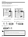
Setting the printing area in the left-right direction (the direction of carriage movement)
To change the start point for printing, use the [BASE
POINT] key. At this time, the printing area does not
change.
Follow the step in both "Specifying a location in the
lengthwise direction" and "Specifying a location in the
left-right direction (the direction of carriage movement)"
to set the start point.
* Returning the
start point in
the left-right
direction to its
original
location
Margin (value set for [PAGE MARGIN])
Printing area
Origin
Starting location in the
lengthwise direction
"Specifying a location in
the lengthwise direction"
Starting location in the left-right direction
"Specifying a location in the left-right direction (the
direction of carriage movement)"
49
User's Reference
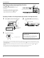
Specifying a location in the lengthwise direction
Knife guide
Use the [ ] and [ ] keys to move the material to the
location where you want to start printing.
In the figure, the next printing operation starts from the
location shown.
* For roll material, when the material has been returned
toward the back of the unit with the [ ] key, manually
roll the material back onto the roll so that all of the
material at the back of the unit is stretched taut.
The next printing operation starts here.
Reflective tape
Front edge of the material
Print-start line
Specifying a location in the left-right direction (the direction of carriage movement)
1
Press the [
] key to move the carriage to the present
starting location for printing in the left-right direction.
2
Use the [
] and [
] keys to line up the new
starting location for printing with the left edge of the
carriage.
Left edge of the carriage
Starting location for
printing in the left and
right direction
3
Right-hand edge of
the material
Press the [BASE POINT] key.
To release the starting location that
has been set...
The BASE POINT LED lights up
The origin point is set.
• Set a new starting location in a different location.
• Press the [SETUP] key to cancel the setup for the
material (making the SETUP LED go out).
- If the carriage moves away from the standby position when not printing, problems such as drying-out of the printing heads or dot drop] key to move the carriage, the carriage returns
out during printing may occur. For this reason, about 60 seconds after pressing the [
to the standby position.
] and [
] key is
Also, the carriage returns to the standby position when about 20 seconds passes during this interval after the [
released.
If the setting could not be made in within the time limit, then do the setting over again from the beginning.
- The starting location set by pressing the [BASE POINT] key is released after printing one page.
50
User's Reference
Setting the printing area in the left-right direction (the direction of carriage movement)
* This can be set only at the time of material setup.
1
Press the [MENU] key and [ ] key to make the
following screen appear on the display.
2
Press the [ENTER] Key.
The carriage indicates the present location of the righthand edge of the printing area.
The following screen appear on the display.
MENU
PRINT AREA
PRINT AREA
MOVE TO R-EDGE
Starting location for
printing in the left and
right direction
3
Press the [ ] key to make the following screen
appear on the display.
Setting the right-hand edge
] and [
] keys to move the left edge of
Use the [
the carriage to the location that you want to make the
right-hand edge of the printing area. Press the
[ENTER] key to lock in the setting with an audible
beep.
4
Right-hand edge of
the material
Press the [ ] key to make the following screen
appear on the display.
The carriage indicates the present location of the lefthand edge of the printing area.
PRINT AREA
MOVE TO L-EDGE
PRINT AREA
SET R-EDGE
Left-hand edge
of the material
Left-hand edge of
the printing area
Left edge of the carriage
Continued on the next page.
51
User's Reference
5
Press the [ ] key to make the following screen
appear on the display.
Setting the left-hand edge
] and [
] keys to move the left edge of
Use the [
the carriage to the location that you want to make the
left-hand edge of the printing area. Press the [ENTER] key to lock in the setting with an audible beep.
6
Press the [ ] key to make the following screen
appear on the display.
Press the [ENTER] key.
PRINT AREA
EXIT
PRINT AREA
SET L-EDGE
Left edge of the carriage
When the location of the right- or left-hand
edge could not be set at the specified
place, [PRINT R-EDGE (or L-EDGE)
SET ERROR] appears on the display. The
problem may be one of the two situations
described below.
- The location specified for the left-hand
edge was farther to the right than the
location of the right-hand edge.
- If the carriage moves away from the standby position when not printing, problems such as drying-out of the printing heads or dot drop] key to move the carriage, the carriage returns
out during printing may occur. For this reason, about 60 seconds after pressing the [
to the standby position.
] and [
] key is
Also, the carriage returns to the standby position when about 20 seconds passes during this interval after the [
released.
If the setting could not be made in within the time limit, then do the setting over again from the beginning.
- After setting the printing area, pressing the [SETUP] key to cancel the setup for the material (making the SETUP LED go out) cancels
the printing area that has been set.
- Using [PRINT AREA] to set the printing area when the starting location in the left-right direction has been specified with the [BASE
POINT] key, the setting made with the [BASE POINT] key is canceled.
52
User's Reference
Making Corrections for Printing
Feed Correction
This corrects for errors in the amount of feed of the grit rollers due the type of material.
Be sure to make this setting when you have replaced the material with a different type.
Correcting the amount of feed improves the dot-positioning accuracy in the feed direction, which can help enhance image quality.
When performing test printing for feed correction, load the material correctly (see "Setup for Printing -- 1 Loading the
Material"). If the material is not loaded correctly, an accurate test pattern may not be output.
When you use the program to set a correction value for the amount of feed, the program’s setting takes priority. The
setting made with the control panel for the machine takes effect only in cases where the program does not perform
correction of the amount of feed.
1
Press the [MENU] key and [ ] key to make the
following screen appear on the display.
2
Press the [
] key to make the following screen
appear on the display.
MENU
CALIBRATION
3
Press the [
] key to make the
following screen appear on the display.
CALIBRATION
PRINTING ADJ.
4
Press the [ENTER] key to start printing a test pattern.
Test pattern
PRINTING ADJ.
TEST PRINT
+0.30%
+0.25%
* Printing a Pattern
in Steps of 0.10%
5
+0.20%
Check the test pattern and choose a
value with no displacement.
+0.15%
Value with no
displacement
+0.10%
+0.05%
6
0.00%
Press the [ ] key to make the following screen
appear on the display.
-0.05%
-0.10%
-0.15%
PRINTING ADJ.
ADJUST
7
Press the [
] key to make the following screen
appear on the display.
ADJUST
-0.10%
-0.10%
Current
setting
8
Use the [ ] and [ ] keys to set the value you
checked in step 4, then press the [ENTER] key.
ADJUST
-0.10%
+0.20%
-2.0% to +2.0%
(In steps of 0.05%)
* Test printing prints the pattern in steps of 0.10%.
53
User's Reference
Bidirectional Correction
* Only when the printing direction at the [PRINT MODE] menu has been set to [BI-DIRECTION] (bidirectional)
This adjusts slippage when performing bidirectional printing.
Make this adjustment when you have replaced the material with a different type or adjusted the head height.
1
2
Press the [MENU] key and [ ] key to make the
following screen appear on the display.
Press the [
] key to make the following screen
appear on the display.
BIDIRECTION
TEST PRINT
MENU
BIDIRECTION
3
4
Press the [ENTER] key to start printing a test pattern.
Check the test pattern and choose a value with no
displacement.
Test pattern
Current setting
+15 +14 +13 +12 +11 +10 +9 +8 +7 +6 +5 +4 +3 +2 +1
0
-1
-2
-3
-4
-5
-6
-7
-8
-9 -10 -11 -12 -13 -14 -15
Value with no displacement
5
Press the [ ] key to make the following screen
appear on the display.
BIDIRECTION
ADJUST
7
Use the [ ] and [ ] keys to set the value you
checked in step 4, then press the [ENTER] key.
ADJUST
+0
+5
-15 to +15 (In steps of 1)
54
6
Press the [
] key to make the following screen
appear on the display.
ADJUST
+0
+0
User's Reference
Performing Overprinting
This prints the same image superimposed over the same location a number of times.
When printing materials such as fabric, colors may not come out well with just a single printing pass. Overprinting can achieve darker
printing results.
You can choose either [2] (two passes) or [3] (three passes) as the number of passes for overprinting.
Performing overprinting may result in ink smudges or stretch the fabric.
When you use the program to set the number of passes for overprinting, the program’s setting takes priority.
The setting made with the control panel for the machine takes effect only in cases where the setting for the number of
overprinting passes is not made with the program.
1
Press the [MENU] key and [ ] key to make the
following screen appear on the display.
MENU
OVER PRINT
3
2
Press the [
] key to make the following screen
appear on the display.
OVER PRINT
NONE
NONE
Use the [ ] and [ ] keys to choose the number of
passes (two or three), then press the [ENTER] key.
OVER PRINT
NONE
2
55
User's Reference
Setting the Page Margins
This makes the setting for the margin between pages.
When outputting a number of pages continuously, you can establish a margin between the pages.
You can set this in a range of 0 mm to 100 mm (in 10 mm steps).
This is set at 20 mm when shipped from the factory.
Start of the next output
Start of the next output
10 mm
(3/8 in.)
End of output
End of output
10 mm (3/8 in.)
Location where separated
10 mm (3/8 in.)
Margin (value set for [PAGE MARGIN])
Margin (value set for [PAGE MARGIN])
[When the material is not cut off]
1
Press the [MENU] key and [ ] key to make the
following screen appear on the display.
MENU
PAGE MARGIN
3
Use the [ ] and [
the [ENTER] key.
[When the material-cutting command is enabled]
2
Press the [
] key to make the following screen
appear on the display.
PAGE MARGIN
20mm
20mm
] keys to set a margin, then press
PAGE MARGIN
20mm
10mm
0 to 100 mm
(In steps of 10 mm)
When separating the material with the margin set at [0], the position where the material is separated and the end of
printing may not match.
When performing continuous printing with the margin set at [0], image quality just after starting to print may be poor on
the second page or after. Also, dot drop-out or overlap may occur at the page borders.
When you use the program to set the page margins, the program’s settings take priority. The setting made with the
control panel for the machine takes effect only in cases where the settings for page margins are not made with the
program.
56
User's Reference
Adjusting the Height of the Printing Head
You adjust the height of the printing head to match the thickness of the mounted material. You can adjust the head height by moving the
lever shown in the figure to any of the positions (1 through 3), where it clicks into place.
The height of the printing head may normally be left set at 3. If the loaded material is thin, lowering the height to the 1 or 2 position may
produce better printing results.
NOTICE
Do not attempt to lower the printing head when any of the following kinds of material is loaded.
The head may strike the material during printing, resulting in a paper jam or causing breakdown or faulty
operation.
-Thick material
-Material that may come loose or warp during printing
1
Detach the cover from the machine.
For information on how to detach the cover, refer to the Cleaning Kit User's Manual that comes with the cleaning kit. See
"Performing Cleaning," steps 1 through 3.
Before you begin the task, be sure to read the cautions printed on the cleaning kit.
2
Move the lever to adjust the height of the printing head.
Height of the printing head
3 2
1
3
High
2
1
Low
Lever
* Be sure that the carriage
is in standby position
before attempting to
move the lever.
3
Attach the cover on the machine.
For information on how to attach the cover, refer to the Cleaning Kit User's Manual -- "Performing Cleaning," step 22.
When the height of the printing head has been adjusted, it is necessary to perform bidirectional correction (only when
the printing direction for [PRINT MODE] has been set to [BI-DIRECTION]). For more information about bidirectional correction, see "User's Reference -- Making Corrections for Printing -- Bidirectional Correction."
57
User's Reference
Materials
Conditions for Usable Materials
A) Maximum material thickness
: 1.0 mm (0.039 in.) (When head is raised)
B) Maximum diameter for roll material
: 180 mm (7-1/16 in.) (surface to be printed must face outward)
C) Core inner diameter for roll material
: 50.8 or 76.2 mm (2 in. or 3 in.)
D) Maximum weight for roll material
: 20 kg (44.1 lb.)
E) Roll material with a starting edge
that is not taped down
Side view of roll material
58
User's Reference
About the Printing Area
The material's printable width (the direction of carriage movement) is determined by the width of the loaded material. When the
[SETUP] key is pressed after loading the material, the width of the material is detected and the printing area appears on the display. The
printing area is normally 10 mm (3/8 in.) inward from the respective left- and right-hand edges of the material.
When the printable width have been specified with the [PRINT AREA] menu, the margins are in accordance with these setting values.
Printing width
60 mm (2-3/8 in.)
Material
Printing length
Printing area
Origin (0, 0)
10 mm (3/8 in.)
10 mm (3/8 in.)
10 mm (3/8 in.)
When the printable width have been specified with the [PRINT AREA] menu,
the margins are in accordance with these setting values.
Below are listed the widths of material that can be mounted on the SJ-600/500 and the printing widths of the
SJ-600/500.
-Acceptable material width
SJ-600: 210~1625 mm (8-5/14 ~ 64 in.)
SJ-500: 210~1371 mm (8-5/14 ~ 54 in.)
-Printing width
SJ-600: 210 ~ 1615 mm (8-5/14 ~ 63-9/16 in.)
SJ-500: 210 ~ 1361 mm (8-5/14 ~ 53-9/16 in.)
59
Description of Keys
Description of Keys
Key
Top
menu
Submenu
Setting
range
Default
value
—
—
This switches on and off the sub power . When the
power is switched on, the POWER LED lights up.
—
—
—
—
This detects the presence of material, and its dimensions,
and shows the printable size on the display.
The SETUP LED flashes while detection of material
width is in progress. When setup finishes, the SETUP
LED lights up continuously.
Also press this key when removing the material.
—
—
—
—
The [PAUSE] key pauses operation. The PAUSE LED
lights up while paused.
Pressing this key again cancels the paused state.
Holding down the [SETUP] key for about 1 second
while paused causes remaining data to be cleared and
cancels the material's setup state.
—
—
—
—
This sets the print-start location in the horizontal
direction (the direction of carriage movement). For more
information, see "User's Reference -- Printing at the
Desired Location -- Specifying a location in the left-right
direction (the direction of carriage movement)."
—
—
PRINT
MODE
—
This displays the [PRINT MODE] menu for setting
image quality.
This is used to specify the printing quality and unidirectional or bidirectional printing.
Settings cannot be made while printing is in progress.
To exit the [PRINT MODE] menu screen, press the
[MENU] key or the [CLEANING] key or the [SETUP]
key.
For more information, see "Setup for Printing -- Setting
the Printing quality and Printing direction."
[PRINT
MODE]
PHOTO
SUPER
FINE
FINE2
NORMAL
FAST
DRAFT
[PRINT
MODE]
FINE2
Function
[PRINT
DIRECTION]
BI-DIRECTION
[PRINT
DIRECTION]
UNI-DIRECTION
BI-DIRECTION
—
60
—
This displays the [HEAD CLEANING] menu for
cleaning of the printing head. Before starting to print,
you can carry out a printing test to check the printing
quality.
You can perform cleaning while in any state. Note that
[TEST PRINT] is not displayed while the printing is in
progress.
[TEST PRINT]: Performs a printing test within an area
of approximately 108 mm (4-5/16 in.) by 18 mm (6/8
in.). If there is a problem, then continue by carrying out
cleaning from the [START] menu.
[START]: Begins cleaning of the printing heads. After
cleaning, carry out a printing test to make sure there are
no problems.
For more information, see "Setup for Printing -- 2 Test
Printing" and "Maintenance -- Cleaning the Printing
Heads."
—
—
Description of Keys
Key
Top
menu
Submenu
Function
Setting
range
Default
value
—
—
This cuts off the material at the present location of the
printing-start line. Press this to cut off the portion already
printed from the roll.
You cannot sever a piece of material while printing is in
progress.
For more information, see "Remove the Material."
—
—
—
—
These move the material and the carriage.
When a menu is displayed, these move among the menu
items.
—
—
—
—
This is used to accept, execute, or save the item shown
on the display.
—
—
—
—
This enters the menu mode.
When a menu is displayed, the [ ] and [
move to the next menu,
the [
] moves to a submenu, and the [
moves to the previous screen.
—
—
MENU
LANGUAGE
—
] keys
] key
This sets the language for screen messages. You can
select either English or Japanese.
ENGLISH
JAPANESE
ENGLISH
+
61
Description of Menu Items
Description of Menu Items
Description of Menus
Pressing the [MENU] key enters the menu mode.
Top
menu
SHEET
TYPE
PRINT
AREA
Submenu
Function
—
This is used to select either transparent or opaque material.
Select [OPAQUE] when the material loaded on the unit is not transparent. When using transparent material or when the printing area cannot
be detected, select [CLEAR].
For more information, see "What to Do If... -- [INVALID SHEET]
appears and the material cannot be detected even when the [SETUP]
key is pressed."
OPAQUE
CLEAR
Default
value
OPAQUE
MOVE TO
* This appears only when the material is in a loaded state.
R-EDGE
This sets the printing area in the left-right direction (the direction of
SET R-EDGE carriage movement) of the loaded material.
With transparent material, automatic detection of the material width is
not performed. In such cases, use the [PRINT AREA] menu to specify
MOVE TO
L-EDGE the printing area in the left-right direction. Even when using opaque
material, this can be used to specify a specific area for performing
SET L-EDGE printing.
Pressing the [ENTER] key while [MOVE TO R-EDGE] or [MOVE TO
L-EDGE] is displayed moves the carriage to the currently set right- or
EXIT
left-hand edge of the material.
When setting a new printing area, make the setting with [SET REDGE] or [SET L-EDGE].
For more information, see "User's Reference -- Printing at the Desired
Location -- Specifying a location in the left-right direction (the
direction of carriage movement)."
Press [EXIT] to quit this menu.
—
—
Before starting to print, you can carry out a printing test to check the
printing quality.
If the printing test shows a problem, clean the printing head.
Because cleaning subjects the head to wear and consumes ink, it should
only be performed when absolutely necessary. Performing cleaning
from the [POWERFUL] menu in particular subjects the head to early
wear and used up large amounts of ink.
[TEST PRINT]: Performs a printing test within an area of approximately 108 mm (4-5/16 in.) by 18 mm (6/8 in.). If a problem is found,
then continue by carrying out cleaning.
[NORMAL]: Performs cleaning of the printing heads. After cleaning,
carry out a printing test to make sure there are no problems with
printing quality.
You should usually choose [NORMAL]. ([CLEANING] does the
same thing as [HEAD CLEANING] - [START] displayed when the
[CLEANING] key is pressed.)
[POWERFUL]: Used when performing cleaning with [NORMAL]
several times does not restore the printing quality. After cleaning,
carry out a printing test to make sure there are no problems with
printing quality.
For more information, see "Setup for Printing -- 2 Test Printing" and
"Maintenance -- Cleaning the Printing Heads."
—
—
HEAD
CLEANING
TEST
PRINT
NORMAL
POWERFUL
62
Setting
range
Description of Menu Items
Top
menu
Submenu
Function
Setting
range
Default
value
INK
CONTROL
EMPTY
MODE
When replacement of the ink cartridge becomes necessary while
printing is in progress, this setting determines whether printing
continues or pauses.
This setting is used when the ink cartridge cannot be changed immediately during printing, such as during unattended operation at night.
[LATER] causes printing to continue without pause even if ink refilling
becomes necessary. Printing continues with the small amount of ink
remaining, so the printed image may become faint as the ink runs out.
In general, it should possible to perform about 1 m2 (10 ft2) of printing
once this message appears, although the actual varies widely according
to the amount of ink needed for the particular image. Printing is
continued only for the data currently being printed. Operation stops
after one image is output.
[PROMPT] causes operation to pause immediately when the ink
cartridge needs to be changed. Printing is resumed by replacing the
cartridge and pressing the [PAUSE] key. Please note, however, that the
colors of an image in progress may no longer be perfectly matched if
the unit is allowed to remain paused for two or three hours before
resuming printing.
FILL INK
[FILL INK] : Refills the printing heads with ink. Normally there is no
need to do this, because refilling is automatic.
PUMP UP
[PUMP UP] : Drains ink from the printing heads.
[HEAD WASH] : This washes the printing heads with optionally
HEAD WASH available cleaning cartridges. For more information, see "Maintenance
CHANGE
-- When Moving the Unit... ."
[EMPTY
MODE]
LATER/
PROMPT
BIDIRECTION
This adjusts for slippage when performing bidirectional printing.
This must be readjusted when you have replaced the material with a
different type or adjusted the head height.
TEST PRINT [TEST PRINT]: This menu is for verifying the adjustment.
ADJUST
[ADJUST]: This sets the correction value.
For more information, see "User's Reference -- Making Corrections for
Printing -- Bidirectional Correction."
[ADJUST]
-15 to +15
(In steps of 1)
Correction
value when
shipped
from the
factory
CARIBRATION
This corrects for errors in the amount of feed of the grit rollers due the
type of material.
Be sure to make this setting when you have replaced the material with
a different type.
Make this setting again when horizontal stripes are plainly visible on
printing results.
TEST PRINT [TEST PRINT]: This menu is for verifying the adjustment.
ADJUST
[ADJUST]: This sets the correction value.
For more information, see "User's Reference -- Making Corrections for
Printing -- Feed Correction."
-2.0% to
+2.0%
(In steps of
0.05%)
0%
LATER
OVER
PRINT
—
You can carry out the same printing superimposed over the same
location. When printing materials such as fabric, colors may not come
out well with just a single printing pass.
This should normally be set to [NONE].
For more information, see "User's Reference -- Performing Overprinting."
NONE/2/3
NONE
SLEEP
—
This sets the time that elapses before the unit enters the SLEEP mode.
The SLEEP mode is enabled when the machine has been inactive for a
specified time. (When in the SLEEP mode, the POWER LED flashes
once per second.)
To release the SLEEP mode...
- Touch any key on the control panel. - Send data from the computer.
- Open the front cover. - Move the sheet loading lever toward the back of the unit.
NONE/15
min to
120 min
(In steps of
15 min)
15 min
63
Description of Menu Items
Top
menu
Setting
range
Default
value
Submenu
Function
AUTO
SHEET CUT
—
This selects whether the material-cutting command is enabled or
disabled.
When set to [ENABLED], the material is cut automatically when the
computer sends a material-cutting command.
For more information, see "Remove the Material -- Cut the Material
From the Roll -- When separating the material by pressing the [SHEET
CUT] key."
ENABLE/
DISABLE
ENABLE
PAGE
MARGIN
—
This makes the setting for the margin between pages.
When outputting a number of pages continuously, you can establish a
margin between the pages.
For more information, see "User's Reference -- Setting the Page
Margins."
0 to 100
mm
(In steps of
10 mm)
10 mm
MENU UNIT
—
This selects millimeters or inches as the unit of measurement for the
width displayed on the top menu after setting up the material. When
inch display is used, values are displayed to the first digit to the right of
the decimal point.
mm/INCH
mm
SYSTEM
REPORT
—
This prints the current status of settings and other system information.
—
—
FACTORY
DEFAULT
—
This returns all menu settings to their original values when shipped
from the factory.
For more about the factory defaults for the various settings, see the
"Default value" entry for each menu setting in this section.
—
—
INK LEFT
—
This shows the amount of ink left after each of the ink cartridges has
been installed.
The fewer the markers (" "), the less ink is left.
* If a partially used ink cartridge is removed and reinstalled, or if a
partially used ink cartridge is installed, the cartridge is taken to be
unused, and the displayed amount of remaining ink is not true.
For more information, see "Maintenance -- Check How Much Ink
Remains."
—
—
64
Description of Menu Items
Display Menus Flowchart
For details about each of the menus, see the "Description of Display Menus."
* Selecting the language
for screen messages
MENU LANGUAGE
ENGLISH
Roland SJ-600
Ver.***
When the power is turned
on for the first time, or turned
on after removing the ink
Roland SJ-600
PIGMENT CMYKLcLm
Use
or
to select.
Press the [ENTER] key
to enable the setting.
MENU LANGUAGE
JAPANESE
Roland SJ-600
UNKNOWN INK TYPE
SET CARTRIDGE
[KCMcmY]
INSTALL
DRAIN BOTTLE
SELECT INK TYPE
SOL
CMYKLcLm
SET CL-LIQUID
[KCMcmY]
NOW FILLING INK
NOW HEAD WASH...
DISCARD
DRAIN INK
SETUP SHEET
Load the material and press the [SETUP] key
Settings for [OVER PRINT]
Printable width of
the loaded material
Top
W 1234 mm
OP2
menu FINE
BI-DIR
OP2 = Twice /
OP3 = Three times
* Not displayed when set to
[NONE].
The settings for [PRINT QUALITY]
(Printing Direction) display only in the case
of [BI-DIRECTION].
PRINT QUALITY
FINE
PRINT QUALITY
BI-DIRECTION
PHOTO/SUPER/FINE/FINE2/
NORMAL/FAST/DRAFT
UNI-DIRECTION/
BI-DIRECTION
* When [HIGHSPEED MODE] is set to [ENABLE]
HS-PHOTO/HS-SUPER/FINE/FINE2/NORMAL/FAST/DRAFT
Use
or
to select.
Press the [ENTER] key to enable the setting.
Settings for [PRINT QUALITY] (Printing Quality)
PHOTO/SUPER/FINE/FINE2/NORMAL/FAST/DRAFT
HEAD CLEANING
START
Press the [ENTER] key.
Head cleaning starts.
HEAD CLEANING
TEST PRINT
Press the [ENTER] key
to print a test pattern.
65
Description of Menu Items
MENU
INK CONTROL
MENU
SHEET TYPE
INK CONTROL
EMPTY MODE
INK CONTROL
FILL INK
SHEET TYPE
OPAQUE OPAQUE
OPAQUE/CLEAR
INK CONTROL
PUMP UP
INK CONTROL
HEAD WASH
Displayed only when the material
has been set up.
MENU
PRINT AREA
PRINT AREA
MOVE TO R-EDGE
PRINT AREA
SET R-EDGE
MENU
BIDIRECTION
BIDIRECTION
TEST PRINT
BIDIRECTION
ADJUST
PRINT AREA
MOVE TO L-EDGE
PRINT AREA
SET L-EDGE
PRINT AREA
EXIT
MENU
CALIBRATION
MENU
HEAD CLEANING
HEAD CLEANING
TEST PRINT
HEAD CLEANING
NORMAL
CALIBRATION
TEST PRINT
CALIBRATION
ADJUST
MENU
OVER PRINT
OVER PRINT
NONE
NONE
NONE/ 2 / 3
HEAD CLEANING
POWERFUL
MENU
SLEEP
SLEEP
15min
15 min
NONE, 15 to 120 min.
(In steps of 15 min)
MENU
AUTO SHEET CUT
AUTO SHEET CUT
ENABLE ENABLE
ENABLE/DISABLE
66
Description of Menu Items
EMPTY MODE
LATER
PROMPT
MENU
PAGE MARGIN
PAGE MARGIN
10mm
10mm
0 to 100 mm
(In steps of 10 mm)
LATER/PROMPT
MENU
MENU UNIT
MENU UNIT
mm
mm
mm/INCH
ADJUST
+0
MENU
FACTORY DEFAULT
FACTORY DEFAULT
NOW PROCESSING..
MENU
INK LEFT
K
M
C
m
c
Y
+0
-15 to +15 (In steps of 1)
ADJUST
-0.10
-0.10
-2.0 to +2.0 (In steps of 0.05)
67
What to Do If...
What to Do If...
If the machine doesn't run...
Is the power cord connected correctly?
Connect the power cord to the unit, and plug the other end securely into an electrical outlet. (See “What to Do upon Opening the Carton - 3 Setting Up and Connection” .)
Is the machine power on?
Turn on the power. (See “What to Do upon Opening the Carton -- 4 Installing Ink Cartridge” .)
Has material been loaded (the SETUP LED is lighted)?
If the SETUP LED is not illuminated, make sure the material is loaded correctly and press the [SETUP] key to illuminate the SETUP
LED.
Is the PAUSE LED lighted?
If the [PAUSE] key has been pressed and the PAUSE LED is lighted, the unit has been paused.
To resume printing, press the [PAUSE] key again. The PAUSE LED is extinguished, and printing resumes.
To terminate printing, first stop the transmission of printing instructions from the computer. Then press the [SETUP] key. Hold down
for about 1 second. This deletes the printing instructions that have already been sent from the computer, and printing is stopped.
Is the top menu displayed?
If the top menu isn't displayed, printing doesn't start even when data is sent from the computer.
Top menu
W1234mm
FINE
L ---mm
BI-DIR
Conditions for starting printing
The material must be already set up (with the SETUP LED lighted), and the display must show the top menu. If another menu screen is
displayed, press the [SETUP] key to go back to the top menu. (Pressing the [SETUP] key when another menu screen is displayed does
not cancel the set-up for the material.)
Are the computer and the machine linked with the right cable ?
The type of cable you need is determined by your computer. One which you are sure matches the model of computer being used should
be select.
Is the cable making a secure connection?
Connect securely. (See “What to Do upon Opening the Carton -- 3 Setting Up and Connection” .)
Has the correct driver selection been made for the application software?
Select the appropriate driver.
68
What to Do If...
[INVALID SHEET] appears and the material cannot be detected even when
the [SETUP] key is pressed
If the material loaded on the unit is transparent, then at the [SHEET TYPE] menu, select [CLEAR].
1
Press the [MENU] key and [ ] key to make the
following screen appear on the display.
2
SHEET TYPE
OPAQUE OPAQUE
MENU
SHEET TYPE
3
Use the [ ] [ ] key to select [CLEAR], then press
the [ENTER] key.
Press the [
] key to make the following screen
appear on the display.
4
SHEET TYPE
OPAQUE CLEAR
- When the setting for [SHEET TYPE] is changed after setup for
the material has been performed, the setup for the material is
automatically canceled. If this happens, set up the material
again.
- When using opaque material, return the [SHEET TYPE] setting
to [OPAQUE].
Specify a printing area for the left-right direction (the
direction of carriage movement) that matches the
width of the material. For more information, see "
User's Reference -- Printing at the Desired Location -Setting the printing area in the left-right direction (the
direction of carriage movement)."
When [SHEET TYPE] has been set to
[CLEAR], no detection of the material is
performed when material is loaded. This
means it is necessary to specify a printing
area that matches the actual width of the
material.
When only set to [CLEAR], the printable
width is set to the maximum (SJ-600:1605
mm (63-3/16 in.), SJ-500:1351mm (53-3/
16 in.)).
If the "INK EMPTY" message appears
A cartridge has run out of ink, and printing cannot be started.
If printing data is being sent, this message is displayed and the buzzer sounds. At the same time, operation is paused and the PAUSE
LED flashes. Replace the empty cartridge with a new one and press the [PAUSE] key to start printing.
Clean, attractive printing is impossible
If drop-out occurs with printed images.
Clean the printing heads (see "Maintenance -- Cleaning the Printing Heads").
Is the surface of the platen dirty or scratched?
Clean the platen (see “Maintenance -- When the Product Needs Cleaning”).
Is the material dirty?
Remove superficial soiling, then load the material.
Is the material damaged?
Clean, attractive printing is not possible if the material is damaged or warped.
Use care to keep materials from being damaged while in storage.
Continued on the next page.
69
What to Do If...
During printing, was the front cover opened (executing an emergency stop) or the [PAUSE] key
pressed?
If operation is stopped or paused while printing is in progress, the quality of the image before and after the interruption may differ. It is a
good idea to avoid pausing operation while printing is in progress whenever possible.
Is thick material in use, or does the surface of the material rub against the printing heads?
If material feed is not smooth because the material catches on the head, then adjust the height of the printing heads (see "User's Reference -- Adjusting the Height of the Printing Head").
When the height of the printing head has been adjusted, it is necessary to perform bidirectional correction (only when the printing
direction for [PRINT MODE] has been set to [BI-DIRECTION]). For more information about bidirectional correction, see "User's
Reference -- Making Corrections for Printing -- Bidirectional Correction."
If the type of material was changed, was feed correction performed?
Correcting the amount of feed improves the dot-positioning accuracy in the feed direction, which can help enhance image quality.
If the type of material was changed, refer to "User's Reference -- Making Corrections for Printing -- Feed Correction" and perform
correction for feed.
Printing goes beyond the loaded material
Is [SHEET TYPE] set to [CLEAR]?
When [SHEET TYPE] has been set to [CLEAR], no detection of the material width is performed when material is loaded (printable
width set to maximum).
If transparent material has been loaded, specify a printing area that matches the actual material width (see "User's Reference -- Printing at
the Desired Location -- Setting the printing area in the left-right direction (the direction of carriage movement)").
If opaque material has been loaded, set [SHEET TYPE] to [OPAQUE].
Is the reflective tape dirty?
If the reflective tape becomes soiled, the width of the material cannot be detected correctly.
If the tape becomes dirty, wipe gently with a cloth moistened with water.
Has the material been loaded at an angle?
If the loaded material is not straight, it may extend outside the printing area.
Refer to "Setup for Printing -- 1 Loading the Material" and load the material correctly.
Has the printing area been set to fill the material entirely?
When setting the printing area in the left-right direction (the direction of carriage movement) at the [PRINT AREA] menu, leave a
margin on either side. If the printing area is set to extend all the way to the left right and right edges, a small amount of misalignment
may result in printing beyond the edge of the material.
Material feed is not smooth (slippage occurs)
Is thick material being used?
If the surface of the material rubs against the printing heads and smooth feed is impossible, then adjust the height of the printing heads
(see "User's Reference -- Adjusting the Height of the Printing Head").
When the height of the printing head has been adjusted, it is necessary to perform bidirectional correction (only when the printing
direction for [PRINT QUALITY] has been set to [BI-DIRECTION]). For more information about bidirectional correction, see "User's
Reference -- Making Corrections for Printing -- Bidirectional Correction."
If using sheet material, does the loaded material contact areas such as the stand's media flange?
If the sheet material contacts the media flange or the like at the back of the unit, shift the retainer to a location where the material doesn't
make contact.
If the material touches an obstruction while printing is in progress, normal material feed is not performed, and image quality may suffer
or the material may jam.
Is the sheet material loaded at an angle? Are the left and right edges of the material not straight?
If the material is loaded at an angle or if the left and right sides of the material are not cut straight, the location of the edges may shift as
feed is carried out. This may cause the material to rub against the inner side of the machine or be displaced from the printing area.
Is the roll material loaded correctly?
If the roll material is not loaded correctly, the material may come loose or advance at an angle. Refer to "Setup for Printing -- 1 Loading
the Material" and load the material correctly.
70
What to Do If...
The material becomes jammed
If [MOTOR ERROR : TURN OFF POWER] appears and operation stops
(1) Press the [POWER] key to switch off the sub power.
(2) Remove the jammed material. Cut off any creased or torn portions.
(3) Correct whatever caused the material to jam.
(For example, if thick material has been loaded, then adjust the height of the printing heads.)
(4) Press the [POWER] key to turn on the sub power.
(5) Load the material and carry out setup.
(6) Press the [CLEANING] key to perform head cleaning (see “Maintenance -- Cleaning the Printing Heads”).
(7) Press the [TEST PRINT] key to perform a printing test (see “Maintenance -- Cleaning the Printing Heads”).
(8) Send the printing data and perform printing.
* Jammed material may damage or soil the printing heads. Be sure to perform head cleaning first before sending the printing data.
When printing was continued, but should be started over
(1)
(2)
(3)
(4)
(5)
(6)
Press the [PAUSE] key to pause operation.
Stop sending data from the computer.
Press the [SETUP] key. Hold down for about 1 second (making the SETUP LED go dark).
Press the [POWER] key to switch off the sub power.
Remove the jammed material. Cut off any creased or torn portions.
Correct whatever caused the material to jam.
(For example, if thick material has been loaded, then adjust the height of the printing heads.)
(7) Press the [POWER] key to turn on the sub power.
(8) Load the material and carry out setup.
(9) Press the [CLEANING] key to perform head cleaning (see “Maintenance -- Cleaning the Printing Heads”).
(10) Press the [TEST PRINT] key to perform a printing test (see “Maintenance -- Cleaning the Printing Heads”).
(11) Send the printing data and perform printing.
* Jammed material may damage or soil the printing heads. Be sure to perform head cleaning first before sending the printing data.
Printed lines are misaligned
[Example]
OK: Correct
Not OK: Single lines not produced
If misalignment like in the example occurs when the printing direction for [PRINT QUALITY] has been set to [BI-DIRECTION]
(bidirectional), then carry out correction at the [BIDIRECTION] menu (see "User's Reference -- Making Corrections for Printing -Bidirectional Correction").
Be sure to make this adjustment when you have replaced the material with a different type or adjusted the head height.
The material cannot be separated
Is a blade installed in the separating knife?
If no blade is installed, then install one (see "Maintenance -- How to Replace the Separating Knife").
Is the blade dull or broken?
If the blade has become dull or broken, replace it with the replacement blade included with the unit (see "Maintenance -- How to Replace
the Separating Knife").
* Some materials cannot be separated due to their composition.
Has the [AUTO SHEET CUT] menu item been set to [ENABLE]?
If the material-cutting command has been set to "enable" with the driver, then set [AUTO SHEET CUT] to [ENABLE] (see "Remove the
Material -- Cut the material from the roll").
Has the material-cutting command been set to "enable" with the driver?
When the material-cutting command has not been set to "enable" with the driver, automatic separation of the material is not performed,
even when [AUTO SHEET CUT] has been set to [ENABLE].
71
Error Messages
Error Messages
Error messages
Meaning
Action
MOTOR ERROR
TURN OFF POWER
A motor error occurred.
Recovery from this problem is impossible.
Use the POWER key to switch the power off and
back on again.
After rectifying the cause of the error (a material
jam or the like), switch on the power.
Do not leave the unit with the carriage not in
standby position.
TEMPERATURE
IS TOO HIGH
The air temperature where installed is higher than
the ambient temperature at which the unit can operate (approx. 40°C (104°F) or more higher).
Recovery from this problem is impossible. Use
the [POWER] key to switch the power off. First
drop the temperature of the area where installed,
then switch on the power.
TEMPERATURE
IS TOO LOW
The air temperature where installed is lower than
the ambient temperature at which the unit can
operate (approx. 5°C (41°F) or more lower).
Recovery from this problem is impossible. Use
the [POWER] key to switch the power off. First
raise the temperature of the area where installed,
then switch on the power.
INVALID SHEET
SET SHEET AGAIN
The [SETUP] key was pressed even though no
material is loaded.
Setup was performed with no material at the
correct location.
Load material at the correct location and press
the [SETUP] key again.
[Sheet Type] is set to [OPAQUE], but transparent
material was loaded.
When using transparent material, set [SHEET
TYPE] to [CLEAR] (see "What to Do If... (If the
"INK EMPTY" message appears during setup)").
An attempt was made to load material that is too
small.
Replace with material of loadable size.
The reflective tape is dirty.
Wipe off the grime on the reflective tape, then
perform setup again.
PINCHROLL ERROR
DOWN PINCHROLL
The [SETUP] key was pressed with the pinch
rollers up.
The pinch rollers were raised during setup.
Move the sheet loading levers toward "LOAD"
and lower the pinch rollers, then press the
[SETUP] key (see "Setup for Printing -- Loading
the Material").
BASE POINT ERROR
An attempt was made to set the print-start
location at a position beyond the material.
Use the arrow keys to move the carriage marker
to a place within the printing area, then press the
[BASE POINT] key (see "User's Reference -Printing at the Desired Location").
PRINT R-EDGE
SET ERROR
The setting for the right-hand edge was not made
correctly at the [PRINT AREA] menu.
An attempt was made to set the right-hand edge
to the left of the left-hand edge, or at the same
location as the left-hand edge.
Use the arrow keys to move the carriage marker
to a correct position, then make the setting (see
"User's Reference -- Printing at the Desired
Location -- Setting the printing area in the leftright direction (the direction of carriage movement)").
PRINT L-EDGE
SET ERROR
The setting for the left-hand edge was not made
correctly at the [PRINT AREA] menu.
An attempt was made to set the left-hand edge to
the right of the right-hand edge, or at the same
location as the right-hand edge.
Use the arrow keys to move the carriage marker
to a correct position, then make the setting (see
"User's Reference -- Printing at the Desired
Location -- Setting the printing area in the leftright direction (the direction of carriage movement)").
HEAD DRY-UP
WARNING
The printing head was returned to its standby
position to be capped, canceling current printing
job.
Because emergency stop was effected more than
10 min.
Turn power off by pressing [POWER] key to
reset.
Interrupted printing is not resumed.
Repeat printing from the beginning.
SHEET TOO SMALL
SET SHEET AGAIN
72
Specifications
Specifications
SJ-500
SJ-600
Piezo ink-jet method
Printing method
210 mm to 1615 mm (8-5/16 in. to 63-9/16 in.)
210 mm to 1361 mm (8-5/16 in. to 53-9/16 in.)
Acceptable media widths
210 mm to 1625 mm (8-5/16 in. to 64 in.)
210 mm to 1371 mm (8-5/16 in. to 54 in.)
Width of media that can be cut off
210 mm to 1625 mm (8-5/16 in. to 64 in.)
210 mm to 1371 mm (8-5/16 in. to 54 in.)
Printing width
Conditions for usable
Maximum media thickness: 1.0 mm (0.039 in.)
(When head is raised)
Maximum diameter for roll: 180 mm (7-1/16 in.)
media
Core inner diameter for roll: 50.8 mm (2 in.) or 76.2 mm (3 in.)
Maximum weight for roll: 20 kg (44.1 lb.)
Ink
Type
cartridges
Capacity
Color
Exclusive SOL INK cartridges
220 cc ±5 cc
Six colors: cyan, magenta, yellow, black, light cyan and light magenta
16.7 million colors
Apparent colors
Printing resolution
1440 dpi x 720 dpi
720 dpi x 720 dpi
360 dpi x 720 dpi
(Printing dot resolution)
Distance accuracy
/
/
/
540 dpi x 540 dpi
180 dpi x 720 dpi
Error of less than ±0.3% of distance traveled, or 0.3 mm, whichever is grater (at Roland PET-film, print travel: 1 m (39-3/8 in.))
Automatic cleaning and manual cleaning
Printing heads cleaning
Bidirectional parallel interface (compliant with IEEE 1284: nibble mode)
Interface
RD-RTL, RD-PJL
Instruction system
Auto-sleep
Power-saving function
Printing mode
Maximum: 1.3A/100V to 240V ±10% 50/60 Hz
consumption Standby mode
Maximum: 0.4A/100V to 240V ±10% 50/60 Hz
Power
Acoustic
Printing mode
60dB (A) or less
noise level
Standby mode
40dB (A) or less
Dimensions
Main unit
(According to ISO7779)
2500 mm [W] x 671 mm [D] x 410 mm [H]
2246 mm [W] x 671 mm [D] x 410 mm [H]
(98-7/16 in. [W] x 26-7/16 in. [D] x 16-3/16 in. [H])
(88-7/16 in. [W] x 26-7/16 in. [D] x 16-3/16 in. [H])
2500 mm [W] x 758 mm [D] x 1241 mm [H]
2246 mm [W] x 758 mm [D] x 1241 mm [H]
(98-7/16 in. [W] x 29-7/8 in. [D] x 48-7/8 in. [H])
(88-7/16 in. [W] x 29-7/8 in. [D] x 48-7/8 in. [H])
2664 mm [W] x 860 mm [D] x 960 mm [H]
2410 mm [W] x 860 mm [D] x 930 mm [H]
(104-15/16 in. [W] x 33-7/8 in. [D] x 37-13/16 in. [H])
(94-15/16 in. [W] x 33-7/8 in. [D] x 36-5/8 in. [H])
Main unit
111 kg (244.7 lb.)
100 kg (220.4 lb.)
With stand
128 kg (282.2 lb.)
115 kg (253.5 lb.)
178 kg (392.4 lb.)
163 kg (359.3 lb.)
With stand
Packed dimensions
Weight
/
Packed weight
Environment Power on
Temperature: 15°C to 35°C (59°F to 95°F), Humidity: 35% to 80% (non-condensing)
Power off
Temperature: 5°C to 40°C (41°F to 104°F), Humidity: 20% to 80% (non-condensing)
Accessories
Power cord: 1, Stays: 2, Bolts (Large): 14, Bolts (small):4, Washers: 6, Hexagonal wrench (M6):1, Pipe: 1, Standleg: 1,
Media guide: 1, Caster: 2, Media flanges: 2, Flange retainng pins: 2, Drain bottle: 2, Media clamps: 2, Roland
ColorChoice®: 1, User’s manual: 1, Replacement blade for separating knife: 1, Cleaning kit: 1
73
Specifications
Interface Specifications
Standard
Bidirectional parallel interface (compliant with IEEE 1284: nibble mode)
Input signals
STROBE (1BIT), DATA (8BITS), SLCT IN, AUTO FEED, INIT
Output signals
BUSY (1BIT), ACK (1BIT), FAULT, SLCT, PERROR
Level of input output signals
TTL level
Transmission method
Asynchronous
Parallel Connector
(in compliance with specifications of Centronics)
Signal
number
Terminal
number
Signal
number
SLCT IN
36
18
HIGH***
HIGH*
35
17
GND
NC
34
16
GND
GND
33
15
NC
FAULT
32
14
AUTO FEED
INIT
31
13
SLCT
30
12
PERROR
29
11
BUSY
28
10
ACK
27
9
D7
26
8
D6
25
7
D5
24
6
D4
23
5
D3
22
4
D2
21
3
D1
20
2
D0
19
1
STROBE
GND
Pin Connection
18
1
3.3K
+5V
*=
3.9K
*** =
36
74
19
+5V
R1-020320