1
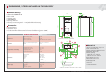
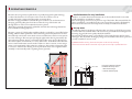
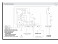
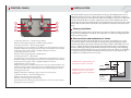
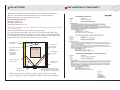
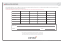
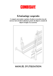
INSTALLATION, OPERATION AND MAINTENANCE
• Biomatic 20
ARITERM SWEDEN AB
Installation, Operation and Maintenance - 2007.10.26- 1/12
CONTENTS
Important Information..................................................................... 2
Dimensions / Items included...........................................................3
Operating Principle...........................................................................4
Wiring Diagram................................................................................ 5
Control Panel .................................................................................... 6
Installation..........................................................................................6
Water Piping ..................................................................................... 7
Filling of Water ................................................................................. 8
Maintenance, Care, Sweeping .......................................................... 9
Advice about Fuel Pellets ................................................................. 9
Pellet Store......................................................................................10
Declaration of Conformity.............................................................10
Installation Protocol........................................................................11
IMPORTANT INFORMATION
• Keep this instruction manual readily available for future use.
• Read the instructions carefully before taking your boiler into service.
• Follow these instructions carefully and carry out care and maintenance work as
recommended.
Notification to building authority
Attention! When you change heating installation this must always be
communicated to the local building authorities.
Sweeping
According to the fire protection laws a chimney shall be swept regularly. This is done
by the local chimneysweep. Sweeping of the boiler shall be carried out in such a manner that good operating economy is achieved. (see under ”Maintenance”) Prepare to
chimney-sweeping by turning off the boiler at least one hour before cleaning to minimize the amount of glowing ash.
Maintenance contract
Ariterm recommends the boiler installation to be made by a company with professional competence. For more information please contact your Ariterm retailer.
Replacing of spare parts
Ariterm recommends that replacing of spare parts is made by authorized serviceman
of Ariterm retailer. The retailer supplies required spare parts and authorized serviceman makes the necessary adjustments and combustion gas analysis when replacing
spare parts.
Guarantee
This boiler manufactured by Ariterm AB is guaranteed to be free of defects in workmanship and materials for a period of 24 months (2 years) from the date of installation. The manufacturer shall not be held liable for faults caused by incorrect installation, incorrect use, freezing, over-temperature or over-pressure. Any attempts made to
repair the product without the manufacturer’s permission or if the guarantee card has
not been returned to the manufacturer, will invalidate the guarantee. The manufacturer shall not be held liable for any possible indirect damage and/or financial loss caused by the boiler.
Ariterm AB reserves the right to decide the method how a possible guarantee repair is
carried out. Ariterm AB is not liable for damages occurred after the expiration of the
guarantee period, but compensation for such incidents may be agreed upon separately
case by case.
ARITERM SWEDEN AB
Installation, Operation and Maintenance - 2007.10.26- 2/12
DIMENSIONS / ITEMS INCLUDED IN THE DELIVERY
Standard delivery
Ø 102 utv.
606
• Shunt valve ESBE TM 20
• Flow switch
• Sweeping gear
• Adjustable feet
• Drain tap DN 15
• Chimney connection piece L = 140 (embedded in chimney)
1019
A=1460
425
213
1500
Accessories
11
261
• Draught limiter
• Oil-burner door
• Combination flue for horizontal and vertical installation (part no. 5206)
180
TECHNICAL SPECIFICATION
Performance
Capacity range, pellets
Capacity, electricity
Hot water production
20 kW
6 kW
480 l +40°C/40 min (12 l/min)
Dimensions
Dimensions (width x depth x height)
Weight
Water contents
606 x 717 x 1500 mm
220 kg
140 l
1
10
410
725
Höjdmått
gäller
ställbara
fötterfeet
Dimensions
areexkl
without
adjustable
2
214
758
49
400 V, 50 Hz
MMJ 4x1,5s
3x10 A
6000 W
55
Mains supply
Mains cable
Fuse size
Connection capacity
305
DN 25 male
Cu Ø 22 mm
DN 25 male
DN 15 female
Ø 102 mm
Ø 100 mm, height min 5 m
100
Heating system
Hot water
Expansion
Drain
Flue
Flue pipe recommendation
5b
5a
8
6
157
7
130
620
Ø114
Ø114
Power supply
0,5-1,5 bar
max 10 bar
120 °C
20 Pa
50
Connections
Design pressure, boiler
Design pressure, cw-hw
Design temperature
Recommended draught
4
9
62
Design values and settings
389
3
Comb.
flue pipe
Kombinationsrökrör
Biomatic 20
1. Drain, hot water return line, DN 15
2. Flue connection Ø 102
3. Shunt opening for additional circuit
4. Expansion DN 25 male
5. Shunt openings
a) Feed line Cu 22 / DN 20
b) Return line Cu 22 / DN 20
6. Cold water inlet Cu 22
7. Hot water outlet Cu 22
8. Cable bushing
9. Sweeping hatch
10. Ash box
11. Flame observation
157
A-dimensions including comb.flue pipe is app. 1710 mm
ARITERM SWEDEN AB
Installation, Operation and Maintenance - 2007.10.26- 3/12
OPERATING PRINCIPLE
Biomatic, the new generation pellet boiler, is specially designed for pellet burning;
to reduce the formation of soot layers on the convection surfaces as far as
possible, the boiler is equipped with upright convection tubes.
Biomatic is equipped with an oversized ash pan to facilitate care and maintenance.
Sweeping primarily takes place from the soot-hatch on top of the boiler and
through the door of the re-box where the burner is placed.
The boiler is primarily designed for pellet fuel. A 6 kW electric heating element has
been installed for backup purposes.
Biomatic consists of a fuel chamber with flue, which is enclosed by a water-filled jacket
holding 140 litre. When pellet fuel is burnt, the heat generated by the burner is transferred directly to the boiler water, which in turn transfers heat to the hot water system
via a heat exchanger. The same principle largely applies when heat is generated by the
electric heating element, but for a somewhat reduced hot water capacity. The heat for
the radiator system is transferred via a 4-way shunt valve. In the shunt valve the boiler
water is mixed with return water from the radiators so that a constant, correct temperature can be maintained in the radiators in relation to the outdoor temperature. This
is a means to achieve better heating economy. The shunt valve can be regulated either
manually or automatically with a regulating device (optional).
Small dimensions for easy installation
Thanks to its modest dimensions Biomatic 20 can be installed in boiler rooms that
would normally be considered too small.
Most of the piping connections are placed on top of the boiler. The terminal block for
electric installation is accessible from the control panel. Service work is facilitated by
the fact that all connections and components are easily accessible from the front.
Hot tap water
The efficient plate heat exchanger will ensure that you always get “fresh” hot tap water.
A strainer has been installed in the cold water line to prevent the heat exchanger from
becoming clogged (the water quality should be checked).
The internal circulation pump is controlled by a flow switch, fitted on the hot water
outlet pipe. The whole heat-exchanger package is located behind the electric panel and
is easily accessible for service work.
ATTENTION! Before servicing, disconnect the power to the boiler by switching
off the mains switches. Work on the boiler may only be carried out by a qualified electrician.
cw
Strainer
hw
Flow switch
Front view of the heat exchanger
installation for hot tap water.
1. Plate heat exchanger
2. Internal circulation pump
1
2
ARITERM SWEDEN AB
Installation, Operation and Maintenance - 2007.10.26- 4/12
WIRING DIAGRAM
ARITERM SWEDEN AB
Installation, Operation and Maintenance - 2007.10.26- 5/12
CONTROL PANEL
INSTALLATION
5
6
8
7
4
1
3
2
The boiler shall be positioned and installed according to the building rules in force.
Minimum clearance in front of the boiler (burner included) is 1000 mm. Clearence
on the top and at least by the other side of the boiler shall be at least 0,5 m. The boiler
must be level. If the floor is uneven, adjustments can be made with the help of four
adjusting bolts (enclosed with the boiler) that shall be fitted to the bottom plate of the
boiler. The air intake duct to the boiler room must have at least the same area as the
flues.
Chimney installation
To embed the angular tube in the chimney, proceed according to the drawing below.
If the tube is embedded as described, you will be able to avoid soot leakage when the
chimney is being swept.
Flue connection and combustion air intake
1. Operating thermostat – electric heating element
Selection of operating temperature of electric heating element
2. Overheat protection – electric heating element
Press this button to reset overheat cut-out. Before reset, check that there is water in
the boiler and that the operating thermostat works correctly. If you cannot reset the
overheat protection, please contact a qualied installation contractor.
3. Operating thermostat – burner
Selection of operating temperature of pellet burner
4. Overheat protection – pellet burner
Press this button to reset overheat cut-out. Before reset, check that there is water in
the boiler and that the operating thermostat works correctly. If you cannot reset the
overheat protection, please contact a qualied installation contractor.
5. Thermometer / Pressure gauge
Display water pressure and water temperature at the top of the boiler. Due to the
stratication of water, boiler temperature varies considerably within the boiler; the
lowest water temperature is measured at the bottom and the highest at the top.
6. Flue gas thermometer
Displays temperature of leaving ue gases at the ue connection point.
7. Operation indicator – electric heating element
Indicates when electric heater is turned on.
8. Switch - heat exchanger circulation pump
Press this button for continuous pump operation (to increase hot water capacity
during electric heater operation).
The combination flue of the boiler allows for connection towards the top as well
as to the rear. Boiler cement is suitable for sealing. Recommended flue gas requirements: brick chimney lined with a Ø 100 mm acid proof thin-walled tube or an acid
proof Ø 100 mm element chimney. Recommended underpressure in the chimney
is 20 Pa. The height of the gas flue shall be dimensioned according to the building’s
requirements, but should be at least 5 m. If condensation water comes out of the flue,
a condensate drain pan shall be installed in the lower portion of the chimney. The
combustion air intake must not be covered.
ATTENTION! The chimneysweep must
be notied for inspection of the flue.
30
Mortar
CAUTION! The boiler has low flue gas
temperatures, which, under certain
conditions,might lead to condensation
of flue gases.
Flue pipe
30 mm incombustible
insulation
Imbedment into chimney
ARITERM SWEDEN AB
Installation, Operation and Maintenance - 2007.10.26- 6/12
WATER PIPING
Water piping shall be carried out in accordance with current local and national hot
water and building regulations. Safety equipment shall be installed in accordance
with regulations in force. If a closed expansion vessel is used, an approved safety valve,
a pressure gauge, and a vent valve shall be fitted. The safety valve shall be fitted just
above, but not directly on, the boiler in such a manner that the connection with the
boiler cannot be closed off. The connecting line from the boiler to the safety valve must
rise uninterruptedly. Before the boiler is filled with water, the enclosed drain tap shall
be fitted at the bottom of the front panel.
Hot water connections
The hot water connections shall be carried out in accordance with the adjoining piping
diagram. If one of the heat exchanger copper tubes needs cutting, this must be done
with loosened connections to avoid that foreign particles enter the heat exchanger.
ATTENTION! According to current regulations (Sweden), the mixing valve or equivalent regulating
device shall be adjusted so as to limit the temperature of the leaving hot water to a maximum of
65°C.
4
Connections
1. Expansion vessel
2. Safety valve
3. Vent valve
4. Feed line - radiator system
5. Return line - radiator system
6. Hot tap water
7. Cold tap water
8. Shunt valve
9. Circulation pump – radiator circuit
10. Mixing valve – hot water circuit
11. Flow switch
12. Strainer
5
7
6
3
9
2
8
Radiator system and expansion vessel
When the system is being filled, the shunt valve shall be open. The shut-off valves (in
the heat exchanger package for instance) shall be open and the external circulation
pump be turned off. Bleed the system carefully while filling. When the installation has
been in service for a few days, it shall be bled and refilled once again.
Determine the required expansion vessel volume as follows:
Open system: 5% of the heating system water volume.
Closed system: Select the volume of the vessel in accordance with the manufacturer’s
instructions.
In the following table, you will find examples of suitable closed system expansion
vessels.
System volume
(litre)*
Opening pressure
(bar)
Initial pressure
(bar)
300
500
1000
1500
2000
1,5
1,5
1,5
1,5
1,5
0,5
0,5
0,5
0,5
0,5
Vessel volume
(litre)
70˚C 90˚C
18
35
35
80
80
140
80
140
140
200
11
An open system with 500 litre water volume demands at least a 35 litre expansion vessel and a 1500 litre
system volume a 80 litre expansion vessel
10
* System volume = boiler volume + storage tanks + piping volume + radiator volume.
12
1
ARITERM SWEDEN AB
Installation, Operation and Maintenance - 2007.10.26- 7/12
WATER PIPING
A fine filter has already been fitted in the cold water line to the plate heat exchanger.
This filter serves to prevent the heat exchanger from becoming clogged. There is no
need for a safety valve, the heat exchanger volume being less than 2 litre. According to
current regulations, the mixing valve or any equivalent device shall limit the leaving
hot water temperature to a maximum of 65 °C.
Fit the flow switch onto the leaving hot water pipe. It should be placed in the upright
position (vertically) so that the arrow on the black portion of the sensor points
upwards. This means that the arrow shall point in the direction of the flow. Install the
sensor as close to the boiler as possible as the sensor cable must reach down to the
electric connections of the control system. Do not install the flow switch horizontally.
Safety valve and circulation pump
If a closed expansion vessel has been installed in the radiator system, the safety valve
must be checked 4 times a year. Activate the valve by pressing or turning the control
button and check that water escapes from the overflow pipe connecting the valve to the
drain. If the boiler has been out of service for a period of time, the circulation pump
might jam. This is normal. The easiest remedy is to unscrew the air screw and turn the
motor shaft with a screwdriver.
Planning and installation work
Planning and installation shall be carried out in a professional manner , attention
being paid to general and local rules and regulations. Operating pressure is max. 1,5
bar. Before taking the installation into service, and always at the beginning of the
heating season, the following inspection shall be carried out:
• check that the heating system is filled and bled
• check that the circulation pump is working
• check that the system valves are open
• check that the automatic control and safety devices, if any, are in working order
• check that the chimney has the necessary draught and that the fresh air ventilation is
open.
FILLING OF WATER
Before you begin heating, the heating system must be filled with water.
To fill the system, do as follows:
1 Open all shut-off valves, including the shunt valve.
The pump must be switched off.
2 Fill the boiler and the radiator system with water.
Bleed the system at the radiators.
3 Once the system is filled completely, the circulation pump can be started and
heating can begin.
4 When the boiler water has reached its pre-set operating temperature, the pump
should be stopped and the system bled at the radiators once again. This should be
repeated several times.
Remember that much air is enclosed in tap water. The enclosed air volume may reach
as much as 10%, which explains why bleeding takes time – especially where there are
large water volumes. A closed system shall be filled until the pressure gauge indicates
the correct system pressure, i.e. the distance from the pressure gauge to the highest
radiator in meter times 0,1 which gives the system pressure in bar. Adjust the red
needle of the pressure gauge to the same value as the big needle. The desired hot water
temperature value is selected by means of the mixing valve. To save energy, select the
lowest acceptable temperature.
Heating with electric heating element
Ariterm Biomatic 20 has been fitted with a factory wired 3-phase 6 kW electric
heating element. When the electric heater is used for backup purposes, the thermostat
of the heater should be set at 50 °C to prevent it from being turned on unnecessarily.
The operation indicator is lit when the electric heating element is in service.
ARITERM SWEDEN AB
Installation, Operation and Maintenance - 2007.10.26- 8/12
MAINTENANCE, CARE, SWEEPING
Boiler cleaning
Burning solid fuels, even if operation is automated, normally calls for a little more care
and maintenance than oil heating. For Biomatic 20 maintenance has been minimized
as the result of well planned design and a big ash box holding 50 litres.
Ash is removed when necessary. The convection parts of the boiler are to be cleaned
when the flue gas temperature has risen by 20-30˚C above the temperature of a newly
swept boiler.
ATTENTION! Pay special attention to the pellets quality when you receive a new delivery or when
you change supplier.
ATTENTION! Show a great care when emptying the ash as it might be glowing hot. Ash must be
kept in a fireproof container.
The following measures and checks shold be carried out when the boiler is cleaned:
• Switch off the burner an hour before service.
• Lift the soot hatch at the top of the boiler and brush clean the flues.
• Remove the fixing bolts from the burner and loosen the hose and electric connec
tions.
• Pull out the burner and brush clean the walls of the combustion chamber.
• Empty the ash.
ATTENTION! Disconnect the power to the boiler before removing the protective housing
ADVICE ABOUT FUEL PELLETS
• Pellet fuel can be manufactured from several different biologically derived raw
materials. Most common is wood, but today there are several alternative materials
available on the market that are suitable for pellets manufacture.
These raw materials have various characteristics that can be advantageous or disadvantageous for pelletised fuel.
Important factors that can be assessed are energy content, size, amount of fines,
moisture content and, last but not least, the price. We recommend that you choose
the fuel that has the lowest cost per energy unit after checking how the fuel performs in the burner. Study carefully the fuel performance after new delivery.
In case of doubt, please contact us at Ariterm.
• Most of the problems that arise on account of inferior fuel quality are the result of
inadequate handling and storage before the fuel reaches the end customer.
If the fuel has high fines content the problem is usually due to separation
during storage or loading.
The formation of sintered ash is due to silicate contaminants (sand). Theses
cannot be discovered before they are used. If you get pellets that produce
sintered ash, a claim must immediately be sent to the pellet supplier.
ATTENTION! If sintered ash is formed, the burn pot must be continuously
cleaned of sintered material (with a table spoon for example).
• Damp pellets can be the result of inadequate handling and transport.
If possible, inspect the pellets before they are unloaded to make sure that
you get clean and dry pellets and no fines.
ATTENTION! Damp pellets must be rejected immediately.
ATTENTION! Show great care when emptying the ash as it can be glowing hot.
FUEL RECOMMENDATION
Raw material
Chemically untreated barkless wood
Diameter
8 mm
Length
15 to 32 mm
Volume weight
over 600 kg/m3
Moisture content
less than 10 %
Ash content
less than 0.7 weight %
Fine material content
max 4 weight %
Melting temperature of ash
> 1100 °C
Energy content
>4,75 kWh/kg
ARITERM SWEDEN AB
Installation, Operation and Maintenance - 2007.10.26- 9/12
PELLET STORE
DECLARATION OF CONFORMITY
Thanks to the pellet feed system the pellet store can be built for bulk deliveries.
The store can either be located inside the house or in a separate building.
Pellets must, however, never be exposed to moisture.
Data for exible feed system:
Maximum climb: 2,5 m
Maximum gradient: 45˚
Outside pipe diameter: 75 mm
Attention! The pellet store can have a maximum of 3 intake openings, and only one intake
can be used at a time.
The store shall be well sealed to avoid the spreading of dust.
As a guide when determining the size of the store, it may be useful to know that
the minimum bulk delivery is normally 3 tons if you wish to avoid freight surcharge.
1 ton of pellets corresponds to about 1,6 m3. To accommodate 3 tons of pellets you
would need a store of at least 6 m3 to have some space to spare.
Bulk filling pipe
Ø 100 mm
Vent pipe Ø 200 mm
Attention!
If filter sack is used
for filling we
recommend
2 x Ø 200 mm
Inspection hatch
600 x 600 mm
Stud 45x95 mm
c/c 600 mm
Slippery plywood
board 16 mm
Horizontal stud
45x95 mm
50˚
2 x horizontal
studs 45x95 mm
Vertical studs
95x45 mm
c/c 600 mm
80 mm
Store pipe (delivered by Ariterm),
see previous page. The whole length
of the store pipe shall be supported.
The drawing represents a stand alone pellet storage bin. If the store is built
against a supporting wall, the sloping studs will have to be arranged differently.
ARITERM SWEDEN AB
Installation, Operation and Maintenance - 2007.10.26- 10/12
INSTALLATION PROTOCOL
After installation the burner has to be adjusted. To test every power range, press plus key for 8 seconds in On/Off menu, then can high, low and min modes be tested
manually. Returning to normal position: Press minus key once.
ATTENTION! In this function, the burner won’t stop when the boiler water reaches desired temperature: boiling risk!
Flue gas temp. High
CO
O2
CO2
Efficiency
Draught (mm)
Fan
Effect %
Flue gas temp. Low
CO
O2
CO2
Efficiency
Draught (mm)
Fan
Effect %
Flue gas temp. Min
CO
O2
CO2
Efficiency
Draught (mm)
Fan
Effect %
Air-fuel ratio
Air-fuel ratio
Air-fuel ratio
INSTALLER
Retailer / Installer
Installed by
Inst. date
If these instructions are not followed during installation, operation and maintenance,
the obligations of Ariterm AB under the warranty regulations are no longer binding.
Ariterm reserves the right to alter any details and specifications without prior notice.
ARITERM SWEDEN AB
Installation, Operation and Maintenance - 2007.10.26- 11/12
ARITERM SWEDEN AB | Flottiljvägen 15
39241 Kalmar | www.ariterm.se | 0771-442850