1
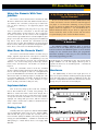
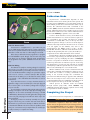
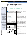
Project
This Month’s
Projects
by Steve Russell
PIC-Based Archos
Remote Control
A Great Use for a Small PIC
Archos Remote . . . .44
Digital Project . . . . . 52
T
The Fuzzball
Rating System
To find out the level
of difficulty for
each of these
projects, turn to
Fuzzball for
the answers.
The scale is from
1-4, with four
Fuzzballs being
the more difficult
or advanced
projects. Just look
for the Fuzzballs in
the opening header.
You’ll also find
information included
in each article on
any special tools
or skills you’ll
need to complete
the project.
Everything For Electronics
NUTS & VOLTS
Let the
soldering begin!
44
his project provides a wired remote
control for certain members of the
Archos family of hard disk-based
Jukebox MP3 players and recorders. Key
features of the design are:
•
•
•
•
•
Low component count and cost.
Simple construction.
Compatible with a small enclosure.
Runs off a single battery.
Long battery life.
Introduction
Although there are now many different
audio compression technologies available,
MP3 is, without dispute, the most widespread
and best supported of those used for moving
music around on the Internet and for carrying
it with you as you travel. Following on
the heels of small capacity (64-128 MB)
solid-state players that hold about an hour or
Figure 1. Tip and ring connections.
two of music, there are now a number of hard
disk-based MP3 players and recorders
available, such as those offered by Archos
(www.archos.com).
While not as robust as the solid-state
players — which have disk sizes up to 20 GB
— these devices can store the equivalent of
300 CDs in MP3 format — even more if you
are prepared to sacrifice sound quality for
greater compression. The good news is that
they are becoming more affordable as the
cost of disk storage continues its downward
trend. While most would agree that they lack
the elegance of products such as the Apple
iPod, the Archos players come with a much
more palatable price tag.
Price is not the only advantage that
Archos can claim over its rivals. Several of the
company’s products have attracted an active
open-source community that is developing
alternative software for them. This software,
called Rockbox (http://rockbox.haxx.se), is
rapidly becoming superior to the standard
software. The Rockbox site also offers lots of
information about the Archos hardware and
ways in which to modify it, either directly or
via pointers to other websites. I’ve upgraded
my 20 GB Jukebox Recorder with a 40 GB
drive, thanks to information available there.
This is a relatively simple upgrade, but
there are more tricky ones to be found if
you like modifying your gadgets and feel
adventurous.
Looking through the mailing list hosted at
the Rockbox site, I found enough information
to be able to design and construct a wired
remote control for my recorder. Archos offers
a remote, but only as a component within a
complete travel kit that also includes a power
adapter, cassette adapter, and headphones —
all of which I already have. Building my own
remote seemed to be a much better option
than paying for things I didn’t need.
MAY 2004
PIC-Based Archos Remote
Using the Remote With Your
Jukebox
The remote control described here should work with
all Archos Jukebox Recorder and Jukebox Studio devices
(see Sidebar). For convenience, I’ll just say recorder from
now on when referring to all supported players and
recorders.
A stereo headphone jack plug has a tip, ring, and
sleeve to provide the connections to the left and right
audio signals and the ground reference. The recorder has
an extra connection for the remote in the headphone
socket, which is grounded when a normal headphone jack
plug is connected. The remote jack plug has an additional
ring that is used to transmit the commands from the
remote to the recorder. The headphones are then plugged
into the remote, which passes the audio straight through to
them. These connections are illustrated in Figure 1.
How Does the Remote Work?
The remote communicates with the recorder using a
simple, eight-bit, asynchronous serial protocol, with the
least significant bit (LSB) first — at 9,600 bits per second
— using one start and one stop bit. Six commands are
defined — one each for Play, Stop, Volume Up, Volume
Down, Next, and Previous. The details are shown in
Figure 2.
These six commands work for both the standard
Archos software and the alternative Rockbox offering. The
remote code was designed so that it is a straightforward
process to add additional commands to the standard ones.
This means that it is relatively simple to modify the code
to implement additional commands, should the Rockbox
developers add functions (or, since Rockbox is open
source, should you decide to add your own).
Implementation
Is My Player or Recorder Supported
by the Remote?
Be sure to check the Archos website (www.archos.com)
to make sure that the remote in the Archos travel kit supports
your player or recorder before embarking on this project. At
the time of writing, the Jukebox Recorder and Jukebox Studio
(player) devices are supported — not the FM Recorder or
Jukebox Multimedia devices. If your device is supported, this
remote should also work as well or better than the Archos
one, particularly if you also use the Rockbox software.
Making Sure the MCU Clock
Is Accurate
An individual oscillator calibration value is stored at
address 0 x1FF in each ’508A during manufacturing. This value
must be loaded into the OSCCAL register to ensure the best
accuracy for the internal clock. Check your programmer
information carefully to make sure you don’t overwrite this
value when programming your PIC.
careful design for minimizing power, this means that a
single CR2032 coin cell will supply sufficient power to
operate the device for an extended period — estimated at
well over a year.
Hardware
The ’508A family of devices has eight pins. Two of
these are for power, with the remaining six being input/output
(I/O) pins that support a number of different modes. The
device’s configuration bits determine their function. In this
design, they are all used as normal I/O pins.
Figure 2. Serial data.
One of the key design goals I had was creating a
remote that would fit into a small, neat package. It is
difficult to achieve this with a home brew design, but a
remote the same size as the recorder was not the answer.
To keep the size down, I decided to use one of the smaller,
eight-pin, low voltage PIC processors, with the intent of
using a surface mount device (SMD) to minimize the size
of the completed unit.
Picking the PIC
I already had some experience with the PIC12C508A
(see my High-Roller article, Nuts & Volts, January 2003),
and felt that this project would also suit this class of
microcontroller (MCU). In addition, Microchip offers a low
voltage part (PIC12LC508A) — available in both DIP and
SMD packages — which will run from a 3 V supply. With
MAY 2004
45
Project
Referring to the schematic in Figure 3, two outputs of
the PIC12LC508A (GP4 and 5) drive a 2 x 3 matrix of
switches. The switch states are read in using inputs GP0,
1, and 3, which are equipped with weak internal pullups
(determined by the device’s configuration bits), so no
external resistors are required. These inputs also support
“wake on pin change,” which allows the PIC to sleep while
waiting for a switch to be pressed. The final output (GP2)
drives the serial data to the Archos Jukebox.
The configuration fuses are set to use the internal
oscillator (leaving all six I/O pins available for use). All
timings are therefore calculated assuming a nominal 4
The basic code design is straightforward. All the
remote has to do is transmit the appropriate command to
the recorder when a switch is pressed. However, there
are a number of factors that make things a little more
complicated. These are:
• Providing an open-drain drive to the Archos, even
though the ’508A’s drivers have totem pole outputs.
• Minimizing power consumption.
Rockbox
http://rockbox.haxx.se
• Debouncing the switches.
PIC MCU information
www.microchip.com
PIC discussion group
www.piclist.com
Eagle PCB layout software
www.cadsoft.de
Everything For Electronics
Design Details
Useful Websites
Archos discussion group
http://groups.yahoo.com/group/archosjukebox6000
NUTS & VOLTS
MHz clock, so each instruction cycle takes 1 µs.
• Dealing with invalid key presses and making the design
Don’t Blow Up Your Recorder!
During development, I was using a 5 V UV EPROM PIC. If
I had inadvertently driven a logic 1 from GP2 while the TRIS
register was set to enable the pin, it would have pushed 5 V
into the recorder data line. This could well have resulted in
permanent damage to my recorder, so I did a lot of testing
before connecting the recorder to the prototype. Be careful
to thoroughly test your code if you make modifications!
Figure 3
46
MAY 2004
PIC-Based Archos Remote
flexible enough
commands.
to
allow
additional
• Repeatedly sending the volume
adjustment commands if the corresponding
switches are held down, so that the volume
continues to increase or decrease, as
required.
• Making sure that data is transmitted at
the correct rate for the Archos to recognize
it. The specification of the ’508A’s internal
oscillator timing is not quite as accurate as
required for serial communications.
Example 1
************************************************************************
‘Now we check the button status and repeat this loop until there has
been no change in button state for 10 ms.
‘
‘NOTE: The timing of this loop is important, since it is used as the
basis for debounce timing. Be careful when modifying the path taken
when the buttons haven’t changed — DEBCNT will need to be modified.
************************************************************************
dbncloop
call
readbtns; [35] Read the button status.
movf
btnstat,w
‘[36] Get current button state.
subwf
buttons,f
‘[37] Compare with last reading
movwf
buttons ‘[38] Save new value. We only need Z flag
btfsc
STATUS,Z; [39] Have they changed?
goto
nobtnchg; [41] NO: Need to see if debounced.
movlw
DEBCNT ‘YES: Start debounce timer again.
movwf
dbnctmr
movlw
RPTDLY ‘Set repeat delay.
movwf
rptdelay
goto
dbncloop; ...and go back to read buttons again.
In the following section, I’ll cover each
of these points in turn. Where appropriate,
I’ll refer to excerpts of the code included in
the article, but you may find it useful to
have the complete code listing (available ‘Buttons didn’t change this time around; decrement timer.
from the Nuts & Volts FTP library at nobtnchg
decfsz dbnctmr,f ; [42] Decrement debounce timer; test if done.
www.nutsvolts.com) on hand.
goto
dbncloop; [44] NO: Go back and read buttons again.
Also, if you’re not familiar with the
’508A’s assembly language, it is worth
put. To overcome this limitation, I implemented one by
getting the datasheet from Microchip (www.micro
using the PIC’s ability to tri-state its output pins.
chip.com).
When the data line is idle, it needs to be at logic 1,
While there’s not enough room in this article to
which for the Archos recorder is 3.3 V. By tri-stating
discuss the entire code listing, I believe that — armed with
(disabling) GP2 using the TRIS register, a pullup in the
the datasheet, the code listing, and the following description
— you’ll soon understand how the remote works.
recorder drives the data line to 3.3 V. To put a 0 into the
data line, GPIO bit 2 must be set to 0 and then the TRIS
register must be set to enable GP2.
Driving the Archos
Important: Be sure to read the information in
The Archos expects an open-drain driver for serial data.
the sidebar before making any changes to the code,
Unfortunately, the ’508A does not have an open-drain outparticularly if you build the remote with a 5 V PIC.
MAY 2004
Circle #105 on the Reader Service Card.
47
Project
MCU’s pre/post-scaler to the watchdog
timer (WDT).
When the user presses a switch,
***************************************************************************
the ’508A wakes up and, after
‘bitdelay
‘
debouncing the switch, sends the
‘
INPUT: The value in bitadjust is initialized at POR to make the
appropriate command to the recorder
entire loop starting at nextbit in xmit take exactly 104 instruction
before going back to sleep. The WDT is
clocks. Increasing or decreasing bitadjust by 1 adds or subtracts 1 clock,
a counter that runs even when the PIC
respectively, to the serial data bit time.
‘
OUTPUT: None
is asleep. When it reaches its terminal
‘
count, it wakes the PIC up. In many
***************************************************************************
designs, the WDT is used to reset the
bitdelay
MCU if something interferes with the
movf
bitadjust,w
‘Get the necessary adjustment
movwf
loopcnt ‘Save it in the delay loop counter
correct operation of the program. For
bcf
STATUS,C‘
but divide by 4 (loop length)
the remote, however, it is primarily
rrf
loopcnt,f
used to wake the PIC up when the
bcf
STATUS,C
user is holding one of the volume
rrf
loopcnt,f
movlw
0x03
‘Get mask for low two bits
adjustment switches down. This allows
andwf
bitadjust,w
‘ ...and isolate them
the remote to send multiple commands
xorlw
0x03
‘ Invert them (0->3, 1->2, 2->1, 3->0)
without the user having to press the
addwf
PCL,f
‘ Use the number to trim the cycle count.
same switch repeatedly.
nop
When another switch or no switch
nop
nop
is held down, the WDT period is set to
bit1
its maximum (nominally 2.3 s), since it
nop
‘This loop is four clocks in length; use
cannot be completely disabled. By
decfsz loopcnt,f calculated value to generate bit timing.
calculating the current drawn by the
goto
bit1
nop
‘Last time through loop has to be four
remote in its various modes and
clocks, too.
making assumptions about how often
retlw
0
the user will press switches, it is
possible to calculate its average power
consumption.
I
assumed
that the user would make an
Power Consumption
average of two key presses for every three minute song
To keep power consumption to a minimum — thereby
for eight hours a day. This gives an average current of
extending battery life — the design ensures that the ’508A
about 12 µA, which means that a 200 µA CR2032 cell
spends most of its time asleep, drawing almost no current
should last for about 700 days — nearly two years.
(about 2 or 3 µA). The MCU’s Option register is set to
wake the device up on a pin state change, so that it
Handling Key Presses
responds when the user presses one or more of the
switches. Other features set in the Option register enable
Mechanical switches usually “bounce” when they
the weak pullup resistors on GP0, 1, and 3 and assign the
change state. This means that, rather than changing
directly from OFF to ON, they oscillate between OFF and
Figure 4. Printed circuit.
ON for a short time (several milliseconds, typically)
before stabilizing in the new state. For a light switch, this
isn’t really a problem, but, for electronic equipment, the
oscillation can be seen as several distinct switch presses
instead of just one. If this occurred for a press of the Next
switch on the remote, for example, the recorder would
skip perhaps four or five songs rather than just moving to
the next one to be played.
To “debounce” the switches when the PIC wakes up
due to a pin change, it reads the switches multiple times
and waits until there has been no change for about 10 ms
(set by DEBCNT). If the switches change before the 10
ms has expired, the debounce timer is started again. The
debounce loop is shown in Example 1.
By the way, if you take a look at the routine that reads
the switch status (readbtns), you’ll see a string of nop
Everything For Electronics
NUTS & VOLTS
Example 2
48
MAY 2004
PIC-Based Archos Remote
instructions (no operation). These allow the switches to be
read accurately and are necessary because the pullup
resistor on GP3 is about 10x larger than the pullups on
GP0 and GP1, causing a delay before this input accurately
reflects the switch status.
Once the switches have been debounced, the data read
from the switches is converted into a command that is used
to determine the necessary action, implemented by a call
(actually a goto) to fntable. To save space, only one- or
two-switch combinations are decoded. If the user presses
three or more switches simultaneously, they are ignored.
For the Next, Previous, Stop, and Play switches, a
single command is sent to the recorder, even if the switch
is held down. When the volume is being changed, however, it is useful to send repeated changes while the switch is
depressed. For Volume Up and Volume Down, therefore,
the WDT period is made shorter (about 140 ms) prior to
sending the initial command and then going to sleep. After
an initial delay of about 750 ms, a repeated command is
sent every time the WDT wakes the PIC up, until the switch
is released.
The six single-switch commands are those we’ve
already discussed. Only one two-switch command is currently
implemented — if the Volume Up and Volume Down keys
are pressed together and held for more than a couple of
seconds, the remote goes into Calibrate mode, which
is discussed in the next section. All other two-switch
combinations are discarded. If additional commands need
to be implemented later, the code can be easily incorporated
Skills
Hardware construction: Rating 2.
The construction of the high-roller is simple. Anyone with
basic electronic skills (soldering, reading a schematic, and so on)
will be able to put the unit together.You will need to be careful
when soldering the surface mount components. Use a fine
point soldering iron and work as quickly as you can.
Software: Rating 2
The software is a little more complicated and uses some
techniques that require some thought to understand. However,
it is well commented and relatively short, so, if you have some
familiarity with PIC assembly language, understanding the code
will not be difficult.
Programming the device requires that you are able to use
a programmer. Alternatively, I can provide a pre-programmed
PIC12LC508A for $10.00, including shipping from the UK.
Anyone wishing to purchase a pre-programmed chip should
first contact me at [email protected]
Affordable Motion Control Products
Robot Building
Blocks
Motor Speed
Control
PID Motor
Position
Control
3
s
n
o
i
t
u
Sol
Solutions Cubed
Phone 530-891-8045
www.solutions-cubed.com
MAY 2004
Circle #58 on the Reader Service Card.
49
Project
Figure 5. The completed remote control.
via a link in fntable.
Calibration Mode
Tools
Everything For Electronics
NUTS & VOLTS
Tools for Construction
Construction is straightforward — just make sure you
get the ’508A situated the right way.The ceramic capacitors I
used were not polarized.Take care in soldering the PIC pins in
particular to make sure that no solder bridges are formed.
Note that you will need a device programmer to program
the PIC12C508A. A quick Google search found many sites
from which you can purchase relatively cheap programmers
and programmer kits (under $100.00 and some for much
less).
Tools for Debug
A multimeter is handy for checking voltages. It is useful to
have access to an oscilloscope to make sure the serial data is
being transmitted before you actually connect the remote to
your recorder. Because GP2 is acting as an open drain output,
you’ll need to connect a resistor between GP2 and the
positive side of the battery to see the data.The resistor value
is not critical — 1K to 10K will be fine. Remember to remove
it afterward!
If you don’t have access to a ’scope, check that there’s no
significant voltage on the serial data pole of the jack plug and
that a resistor pulls it to the battery voltage before trying it
on your recorder.
You should also test that the left and right audio paths are
working correctly.You can do this easily by connecting some
headphones to the remote and briefly connecting a 1.5V AA
or AAA battery between the left and right audios and grounds
on the four pole jack plug.You should hear clicks only in the
selected channel.
As long as you have not made any assembly errors, you’ll
plug the remote into your recorder and, with a little luck, it
will work. If not, you’ll need to attempt to calibrate the device
as described. If calibration doesn’t resolve the problem, check
all of your connections and you may find that an oscilloscope
is really necessary to complete the debug.
50
Asynchronous communication depends on both
transmitter and receiver running at the same speed. The
recorder expects 9,600 bits per second, which equates to
about 104 µs per bit. Since each instruction takes 1 µs to
execute, the subroutine that sends commands to the
recorder (xmit) sends the start bit and then it must take
exactly 104 instructions before sending each successive
bit. The xmit routine uses some of these 104 instructions
up, but calls bitdelay to pad the count out to 104.
It can be shown that the accuracy of the MCU clock
must be better than ±7.7% to ensure accurate reception of
the command by the recorder. The figure for eight-bit
commands is actually ±5.8%, but, as the top two bits
and the stop bit are all logic 1, the less accurate figure is
sufficient. Microchip make the internal clock as accurate
as it can (again, see the sidebar), but, even so, the
specification for the 5
’ 08A’s clock is +7.75%, -11.25%
from 0-70°C. Therefore, calibrate mode allows the user to
modify the bit period by ±16 clock cycles (about ±15%) to
compensate for the widest deviations from nominal.
Pressing Next or Previous in Calibrate mode decreases
or increases (respectively) the transmit bit time by one
instruction cycle by modifying the value of bitadjust.
Because a loop takes a minimum of three instructions, I
used an nop instruction to make the loop four clocks long.
This allowed me to use the two low order bits to calculate
a small jump to add the required extra zero to three clocks.
Take a look at Example 2 to see how this works.
While in calibrate mode, a series of Volume Down and
Volume Up commands is transmitted so that it is easy to
see when the recorder is receiving commands. If the
timing is not accurate enough, the commands are
ignored. From limited testing, it appears that calibration
will not be necessary in most cases, but it is there if it is
needed. Full instructions for calibration mode are given in
the description near the top of the full code listing.
Switch presses in calibrate mode are handled
through another jump table, called caltable. Any
additional functions that may be required can be easily
incorporated via a link in caltable.
Completing the Project
The remote uses few components, so construction is
Acknowledgements
Information required to drive the remote port of
Archos devices was gleaned from Tjerk Schuringa, author of
the original REMOCLONE remote software (implemented
with a 16LF84) and the authors of Rockbox — the amazing
open source alternative to the Archos’ proprietary firmware.
MAY 2004
PIC-Based Archos Remote
Parts List
The parts are all very easily sourced from vendors such
as Digi-Key, Newark InOne (formerly Newark Electronics),
and Future Electronics.Watch out for minimum quantities of
the low power PIC12LC508A. Newark InOne sells single
chips.
S1-S6
IC1
C1
C2
X1
Be an FCC
LICENSED
ELECTRONIC TECHNICIAN
Learn at home in your
spare time.
Single-pole, single-throw push to close switch
PIC12LC508A microcontroller
0.1 µF ceramic SMD capacitor
10 µF ceramic SMD capacitor
Three pole, 3.5 mm stereo jack socket (switched or
unswitched)
Four pole, 3.5 mm stereo jack plug
Battery holder for CR2032 coin cell
very simple. I decided to make a printed circuit board on
which to mount them. The PCB layout was created using
the free version of Eagle (www.cadsoft.de) and the
assembled board is shown in Figure 4. The Eagle schematic and layout files are available from the Nuts & Volts FTP
site (www.nutsvolts.com).
To keep the size down, the battery clip for the CR2032
and the headphone socket are mounted on the opposite
side of the switches, PIC, and capacitors. I also used SMD
components for the PIC and capacitors. Note that you may
have to modify the layout to allow for different battery clip
or headphone socket designs.
Because the switches are pin-in-hole devices, this
meant that (on my single-sided PCB) I had to solder them
on the “wrong” side of the board. For a production
design, it would be much better to design a double-sided
PCB, with the added benefit of avoiding the need for any
links.
Some colored beads to differentiate the buttons, a
graphic, and a coat of silver paint complete the remote
(Figure 5). With it attached to your recorder, the remote
lets you put your recorder somewhere safe — even leaving
it in its protective case — with the remote on hand to
control it.
Happy listening! NV
Earn up to
$100 an hour
and more!
No previous experience needed!
You can earn more money
if you get an FCC License!
Not satisfied with your present income?
Add prestige and earning power to your
electronics career by getting your FCC
Government License.
The Original Home-Study course prepares you for the “FCC Commercial
Radiotelephone License” at home in your
spare time.
This valuable license is your professional
“ticket” to thousands of exciting jobs in:
Communications, Radio-TV, Microwave,
Maritime, Radar, Avionics & more…you
can even start your own business!
No need to quit your job or go to school.
This proven “self-study” course is easy,
fast and low cost!
GUARANTEED TO PASS – You get your
FCC License or your money will be refunded.
Call for FREE facts now!
About the Author
Steve Russell started his working life as a hardware
design engineer. Somewhere along the way, he was seduced
by computers and began designing subsystems of various
types for them, working for a multi-national computer
company. Much later — after a spell in development
management — he decided that salespeople needed his
help and so he moved into technical marketing, but he
still misses the baleful green glow of an oscilloscope in a
darkened lab, late at night.
MAY 2004
(800) 932-4268 Ext. 220
www.LicenseTraining.com
COMMAND PRODUCTIONS
or mail
coupon
today
FCC LICENSE TRAINING - Dept. 220
P.O. Box 3000 • Sausalito, CA 94966
Please rush FREE details immediately!
Name
Address
City
State
Circle #95 on the Reader Service Card.
Zip
51